AIR CONDITIONING
Automatic A/C Wiring Diagram for Ford Crown Victoria LX 2003
 https://portal-diagnostov.com/license.html
Automotive Electricians Portal FZCO
Automotive Electricians Portal FZCO
https://portal-diagnostov.com/license.html
https://portal-diagnostov.com/license.html
Automotive Electricians Portal FZCO
Automotive Electricians Portal FZCO
List of elements for Automatic A/C Wiring Diagram for Ford Crown Victoria LX 2003:
- (at center rear of engine) g106
- (at front of right front fender apron) g102
- (at front of right front fender apron) g102
- (behind right kick panel) g201
- (electronic cluster) instrument cluster
- (near breakout to c1019) s109
- (near breakout to c1046) s113
- (not used)
- A/c clutch field coil (lower right front of engine)
- A/c clutch output
- A/c clutch relay
- A/c compressor cycling switch (in right rear of engine compartment, on a/c accumulator)
- Air bag sliding contact
- Amb temp sens input
- Ambient air temperature sensor (on front of upper radiator support)
- Audio/climate control system
- Autolamp sensor (on upper left side of dash)
- Autolamp sensor)
- Battery
- Battery junction box (bjb) (in right front of engine compartment, behind battery)
- Battery junction box (in right front of engine compartment, behind battery)
- Blend door (heat)
- Blower motor relay
- Blower mtr output
- Blower speed ctrl
- C2145a
- C220b
- C228a
- C228b
- Central junction box (cjb) (below dash, left of steering column)
- Computer data lines system
- Eatc module
- Electronic automatic temperature control (eatc) module (behind center of dash)
- Engine cooling fan motor (front of engine compt)
- Fan down
- Fan up
- Front blower motor
- Front blower motor speed controller (on right rear side of engine compt)
- Front fender apron) g102
- Front panel illum
- Fuse 15a
- Fuse 40a
- Fuse 50a
- G201 (behind right kick panel)
- Ground
- Hot at all times
- Hot in run
- Hot in run or acc
- Hot in run or start
- Ignition
- In car temp sens
- In-vehicle temperature sensor (behind top center of dash)
- Instrument illum
- Interior lights system
- Lighting control module (behind center of dash)
- Message center switch out blend door (cool)
- Nca
- Pcm power relay
- Powertrain control module (pcm) (in engine compartment, on left side of firewall)
- Radio
- Red
- Reference voltage
- Relay signal
- Remote ctrl unit
- Rest
- S113 (in dash panel to headlamp junction harness, near breakout to c1046)
- S122 (in dash panel to headlamp junction harness, left rear of engine compartment)
- S133 (left rear of engine compt)
- S136 (left rear of engine compt)
- S142 (in dash panel to headlamp junction harness, in breakout to engine cooling fan motor)
- S156
- S157 (in engine control sensor & fuel charge wiring harness, near breakout to coil on plug 2)
- S227 (in main wiring harness, near breakout to lighting control module)
- S276 (in main wiring harness, near breakout to autolamp sensor)
- S285 (in main wiring harness, near breakout to adjustable pedal switch)
- Scp bus (+)
- Scp bus (-)
- Sensor ground
- Sunload sens input
- Temp door variable resistor
- Temp down
- Temp up
- Temperature blend door actuator (behind right side of dash, on top of a/c plenum)
- Temperature control module)
- Variable resistor
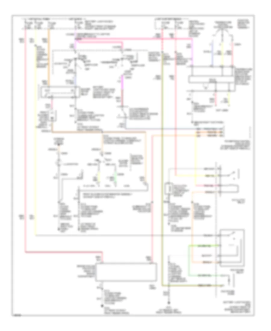
Manual A/C Wiring Diagram for Ford Crown Victoria LX 2003
List of elements for Manual A/C Wiring Diagram for Ford Crown Victoria LX 2003:
- (at front of right
- (at front of right front fender apron) g102
- (behind right kick panel) g201
- (front of engine compartment)
- (not used)
- A/c clutch field coil (lower right front of engine)
- A/c clutch relay
- A/c compressor cycling switch (in right rear of engine compartment, on a/c accumulator)
- A/c switch
- Battery junction box (bjb) (in right front of engine compartment, behind battery)
- Battery junction box (bjb) (in right front of engine compt, behind battery)
- Blower motor relay
- Blower motor switch
- C294a
- C294b
- C294c
- C294d
- Central junction box (cjb) (below dash, left of steering column)
- Control module) s266
- Def
- Def/floor
- Engine cooling fan motor
- Firewall)
- Floor
- Front blower motor (on top right side of
- Front blower motor resistor assembly (on right side of firewall)
- Front fender apron)
- Function selector switch assembly
- Fuse 15a
- Fuse 25a
- Fuse 30a
- Fuse 40a
- Fuse 50a
- G101 (at rear of left front fender apron)
- G102
- G102 (at front of right
- G106 (at center rear of engine)
- High
- Hot at all times
- Hot in run
- Hot in start or run
- Illumination
- Interior lights system
- Low
- Max
- Med high
- Med low
- Mode switch
- Near breakout to coil on plug 2)
- Off
- Panel
- Panel/ floor
- Pcm power diode
- Pcm power relay
- Powertrain control module (pcm) (in engine compartment, on left side of firewall)
- Red/
- S109 (in dash panel to headlamp junction harness, near breakout to c1019)
- S113 (in dash panel to headlamp junction harness, near breakout
- S113 (in dash panel to headlamp junction harness, near breakout to c1046)
- S117 (near breakout to c1010)
- S118 (in dash panel to headlamp junction harness, left rear of engine compt)
- S142 (in breakout to engine cooling fan motor)
- S144 (in dash panel to headlamp junction harness, in breakout to front blower motor)
- S204 (in main wiring harness, near breakout to clock)
- S204 (near breakout breakout to clock)
- S276 (in main wiring harness, near breakout to autolamp sensor)
- S276 (near breakout to autolamp sensor)
- Solid state
- Temperature blend door actuator (behind right side of dash, on top of a/c plenum)
- Temperature control potentiometer
- To c1046)

 Čeština
 Dansk
Dansk Deutsch
 Ελληνικά
 English
 English
 Español
 Suomi
Suomi Français
 Français
 עברית
עברית Magyar
 Italiano
 日本語
日本語 한국어
한국어 Nederlands
 Polski
 Português
 Português
 Română
 Русский
 Slovenčina
 Slovenščina
 Svenska
 Türkçe
 中文 (中国)