CRUISE CONTROL
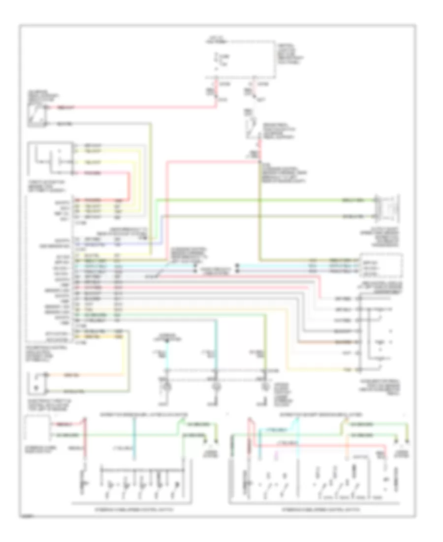
Cruise Control Wiring Diagram for Ford Expedition 2006
List of elements for Cruise Control Wiring Diagram for Ford Expedition 2006:
- (in engine control sensor harness, near breakout to left kick panel)
- (near breakout to rear of exhaust system) s141
- (on brake pedal support) deactivator switch
- Abs control module (at left side of engine compartment)
- Accelerator pedal position sensor (above accelerator pedal)
- Air bag sliding contact (under steering column)
- Bpp sw
- Brake pedal position switch (on brake pedal support)
- C175b
- C175e
- C175t
- C218b
- C270b
- C270e
- Central junction box (cjb) (behind right kick panel)
- Computer data lines system
- Electronic throttle control (etc) motor (top left of engine)
- Etc motor +
- Etc motor -
- Expedition (except eddie bauer & limited)
- Expedition eddie bauer, limited & navigator
- Fuse 7.5a
- Horns system
- Hot at all times
- Hs can +
- Hs can -
- Illumination
- Interior lights system
- Nca
- Off
- Oss sensor sig
- Output shaft speed (oss) sensor (expedition) (on rear of transmission)
- Powertrain control module (pcm) (on right side of firewall)
- Ref vol
- Resume
- S133
- S148
- S150 (in engine control sensor harness, near breakout to left rear of engine compt)
- S277
- Sensor 1 sig
- Sensor 2 sig
- Sensor 3 sig
- Set (+)
- Set (-)
- Sig 1
- Sig 2
- Sig rtn
- Steering wheel radio switch
- Steering wheel/speed control switch
- Sw sig
- Tan
- Throttle position sensor (tps) (on throttle body)
- Vref
 Čeština
 Dansk
Dansk Deutsch
 Ελληνικά
 English
 English
 Español
 Suomi
Suomi Français
 Français
 עברית
עברית Magyar
 Italiano
 日本語
日本語 한국어
한국어 Nederlands
 Polski
 Português
 Português
 Română
 Русский
 Slovenčina
 Slovenščina
 Svenska
 Türkçe
 中文 (中国)
 Hrvatski