ENGINE PERFORMANCE
2.0L
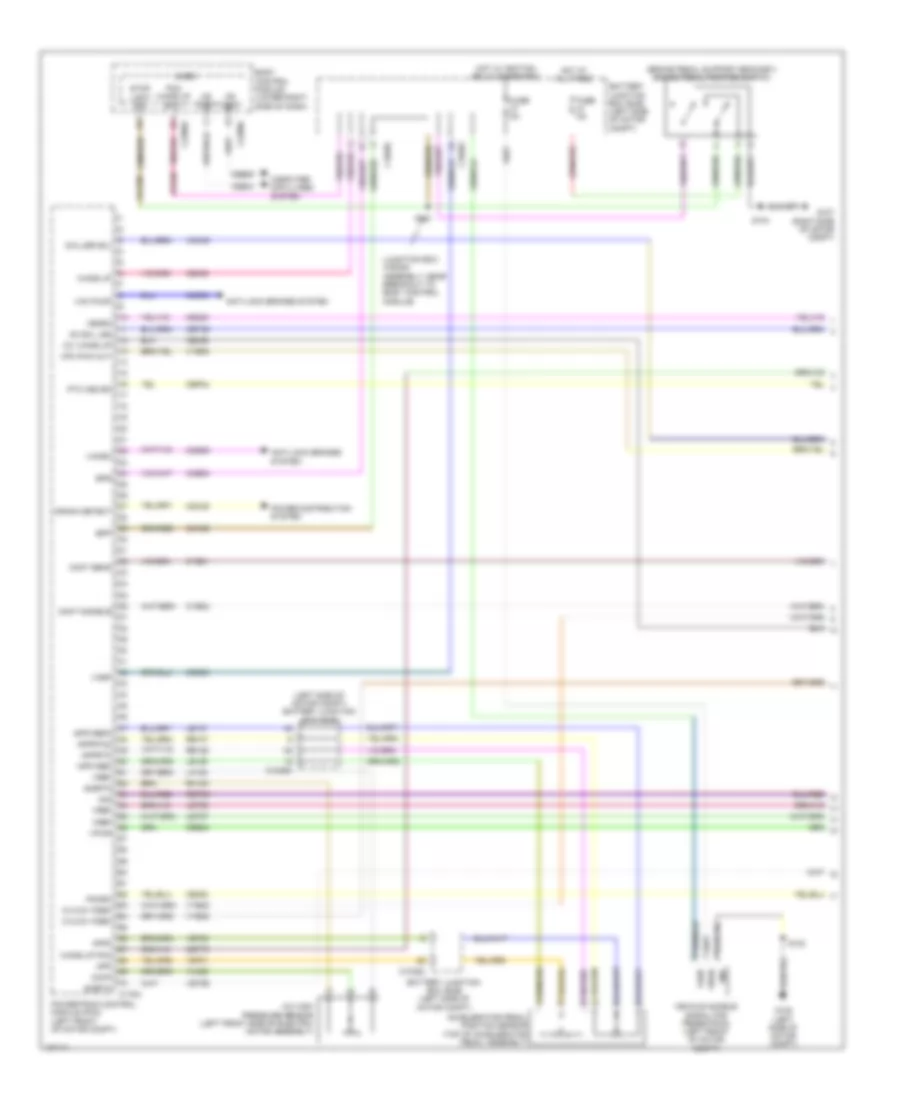
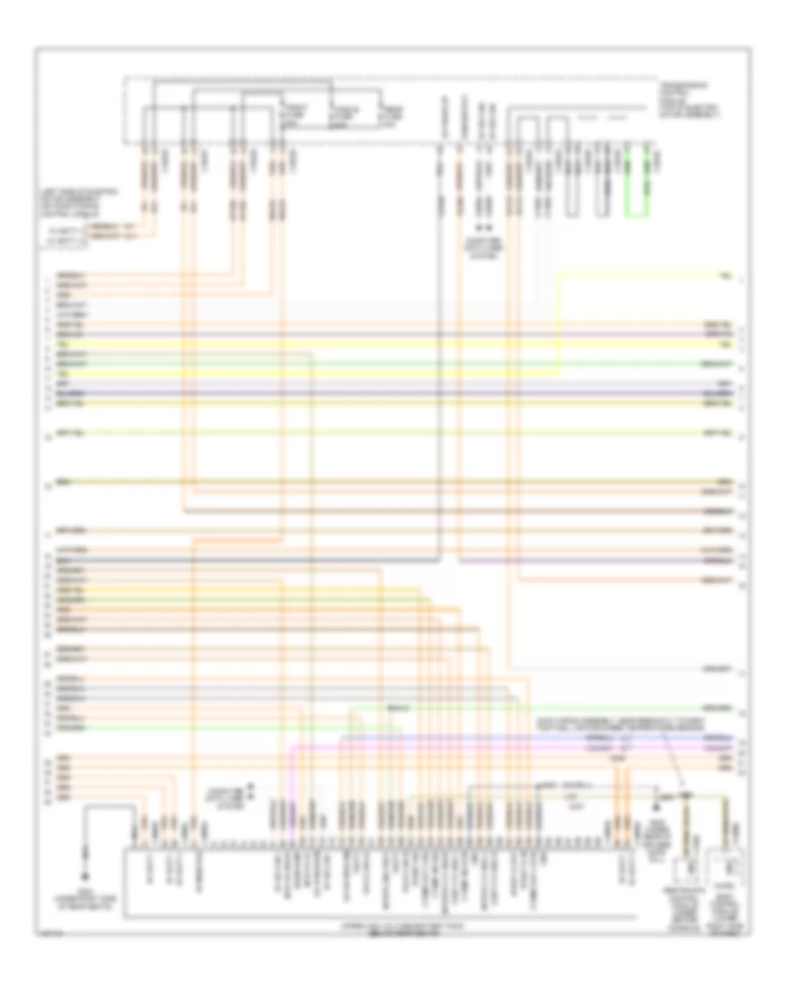
2.0L, Engine Performance Wiring Diagram (1 of 6) for Ford Focus S 2014
 https://portal-diagnostov.com/license.html
Automotive Electricians Portal FZCO
Automotive Electricians Portal FZCO
https://portal-diagnostov.com/license.html
https://portal-diagnostov.com/license.html
Automotive Electricians Portal FZCO
Automotive Electricians Portal FZCO
List of elements for 2.0L, Engine Performance Wiring Diagram (1 of 6) for Ford Focus S 2014:
- (in exhaust, downstream of catalytic converter) heated oxygen sensor (ho2s) 12
- (or ce903)
- 10a
- Aat
- Acceleration pedal position (app) sensor (top of accelerator pedal assembly)
- Accr
- Acpt
- Air conditioning system starting/charging system
- App1
- App2
- Apprtn1
- Apprtn2
- Appvref1
- Appvref2
- Battery junction box (bjb) (left side of engine compt)
- Bpp
- Bps
- C-sigrtn
- C-vref
- C1035c
- C134
- C1750a
- C175b
- Canv
- Cbb08
- Cbb42
- Cca29
- Ccb08
- Cdc12
- Cdc26
- Ce112
- Ce233
- Ce302
- Ce436
- Cet47
- Ch109
- Clth pdl sw
- Computer data lines system
- Cooling fans system
- Cpp (or p/n sw)
- Crank detect
- Cruise control system
- Ens
- Exterior lights system
- Fcv
- Fpc
- Fpm
- From pcm
- Fuse
- Fuse 15a
- G104 (left side of engine compt)
- Gd120
- Ho2s12
- Hot w/ ignition relay energized
- Hs can+
- Hs can-
- Htr12
- Instrument panel cluster (ipc)
- Isp-r
- Le136
- Le137
- Lh108
- Ms can+
- Ms can-
- Nca
- Pcmrc
- Power distribution system
- Power relay (diagram 2 of 6)
- Powertrain control module (pcm) (left side of transmission)
- Pwr gnd
- Re136
- Re137
- Re242
- Reversed gear sw
- Rh107
- Rh108
- S113
- Sigrtn
- Smc
- Smcs
- Starting/ charging system
- Starting/charging system
- Transmission control module (tcm) (left side of transmission)
- Up wake
- Vdb04
- Vdb05
- Ve203
- Ve208
- Ve518
- Ve701
- Ve702
- Ve731
- Vh407
- Vh442
- Vpwr
- Wake up
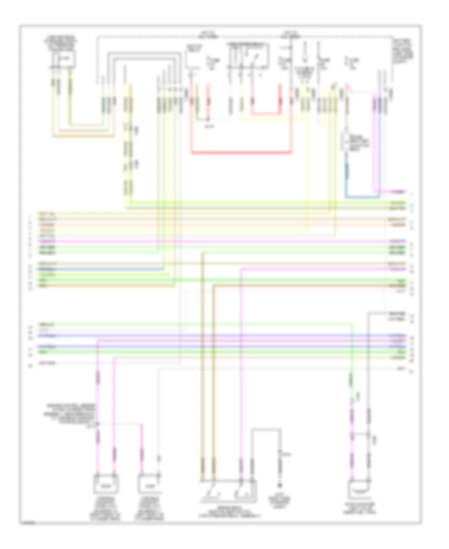
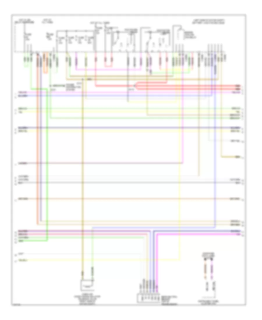
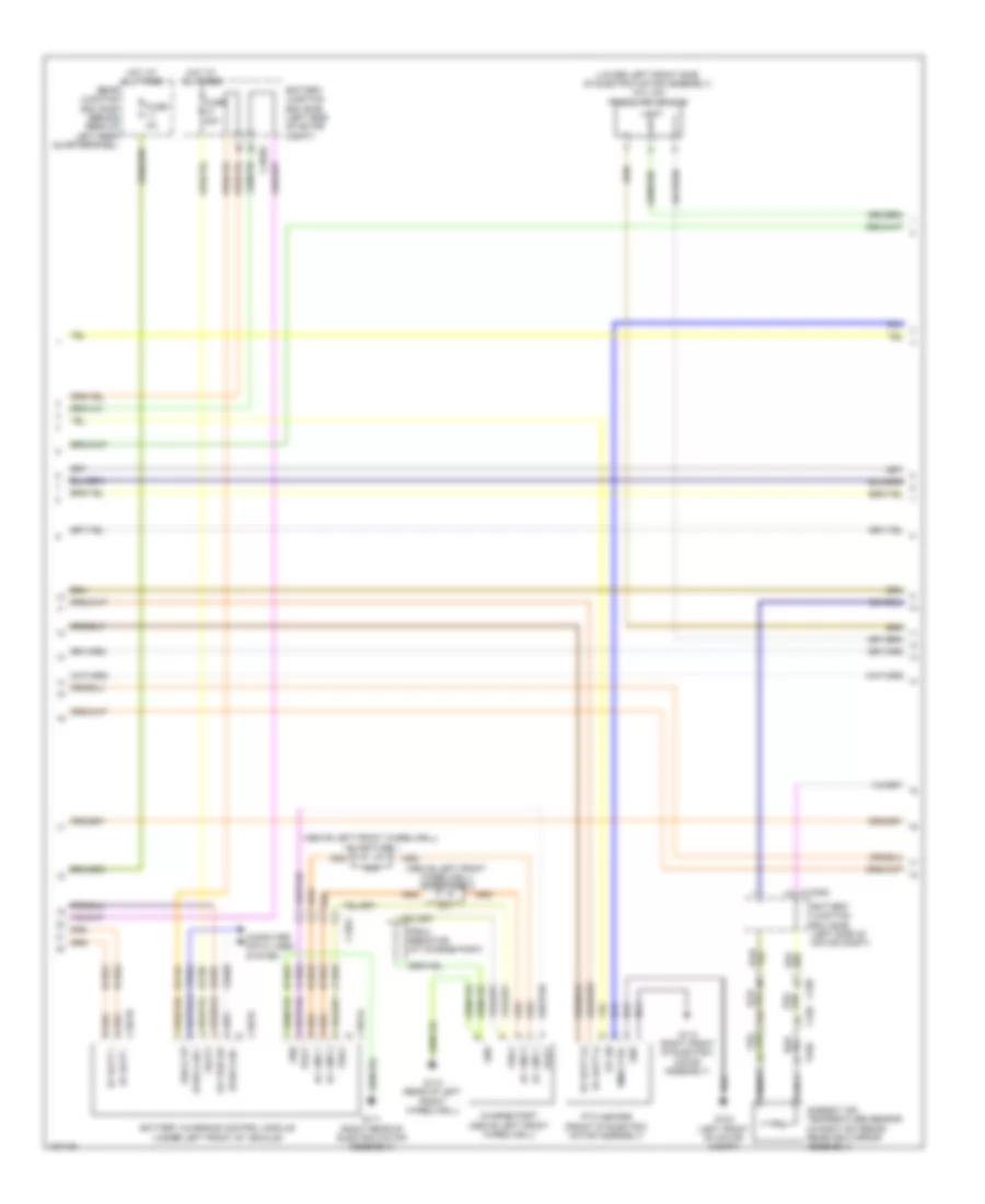
2.0L, Engine Performance Wiring Diagram (2 of 6) for Ford Focus S 2014
List of elements for 2.0L, Engine Performance Wiring Diagram (2 of 6) for Ford Focus S 2014:
- (center rear of engine compt) a/c pressure transducer
- (engine control sensor & fuel charge wiring assembly, near breakout to variable camshaft timing solenoid 11) s114
- A10
- Battery junction box (bjb) (left side of engine compt)
- Brake pedal position (bpp) switch (top of brake pedal assembly)
- C1035b
- C1035c
- C134
- C238
- C340
- Diode (battery junction box)
- Evap canister vent valve (near fuel tank)
- Fuse
- Fuse 10a
- Fuse 30a
- G107 (right side of engine compt)
- Hot at all times
- Ignition relay
- Pcm power relay
- Red
- S104
- S115
- To fuse 32 diagram (1 of 6)
- Variable camshaft timing (vct) solenoid 11 (left front of cylinder head)
- Variable camshaft timing (vct) solenoid 12 (right front of cylinder head)
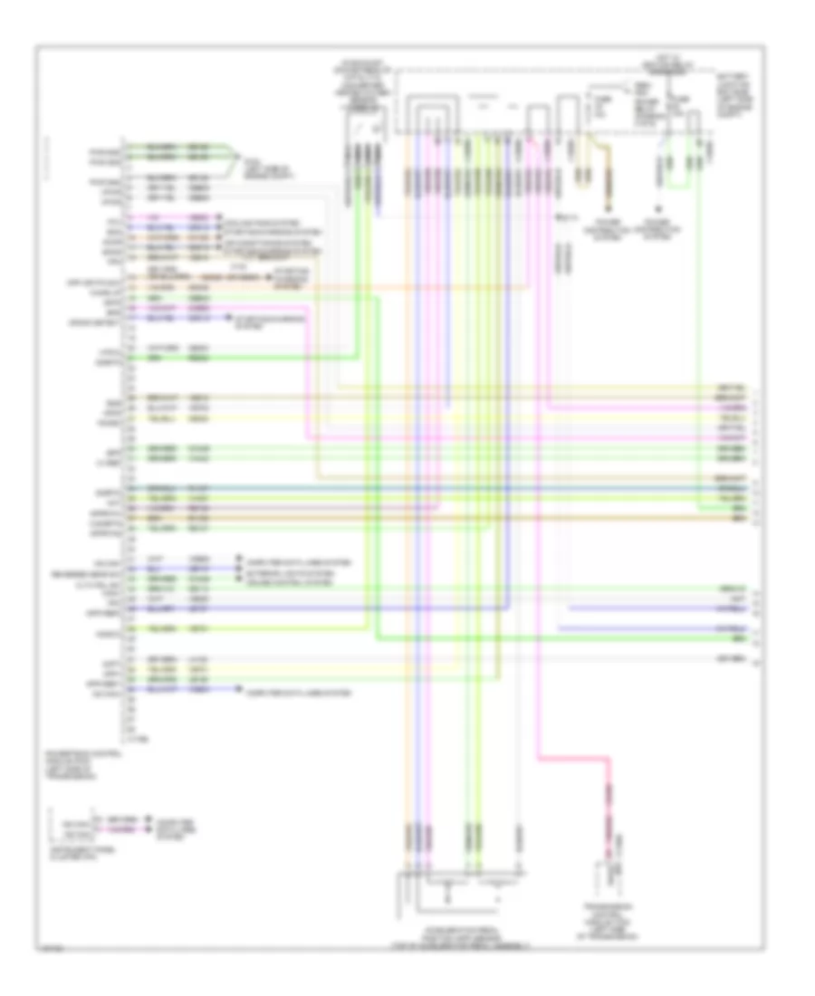
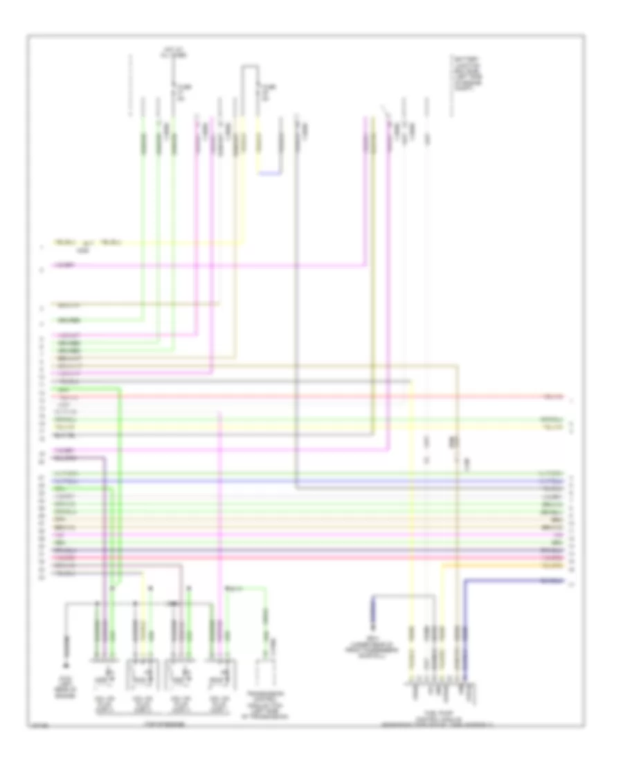
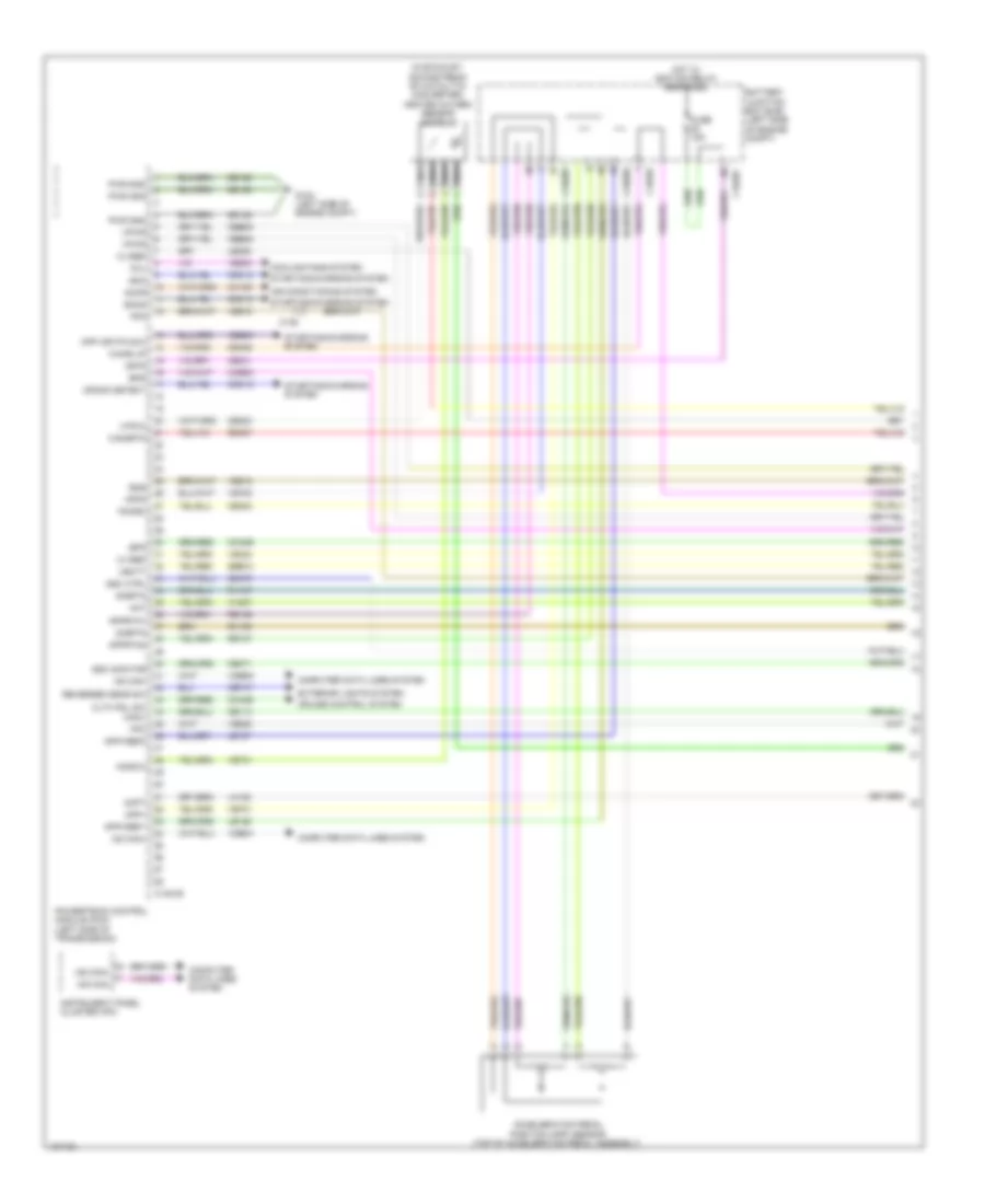
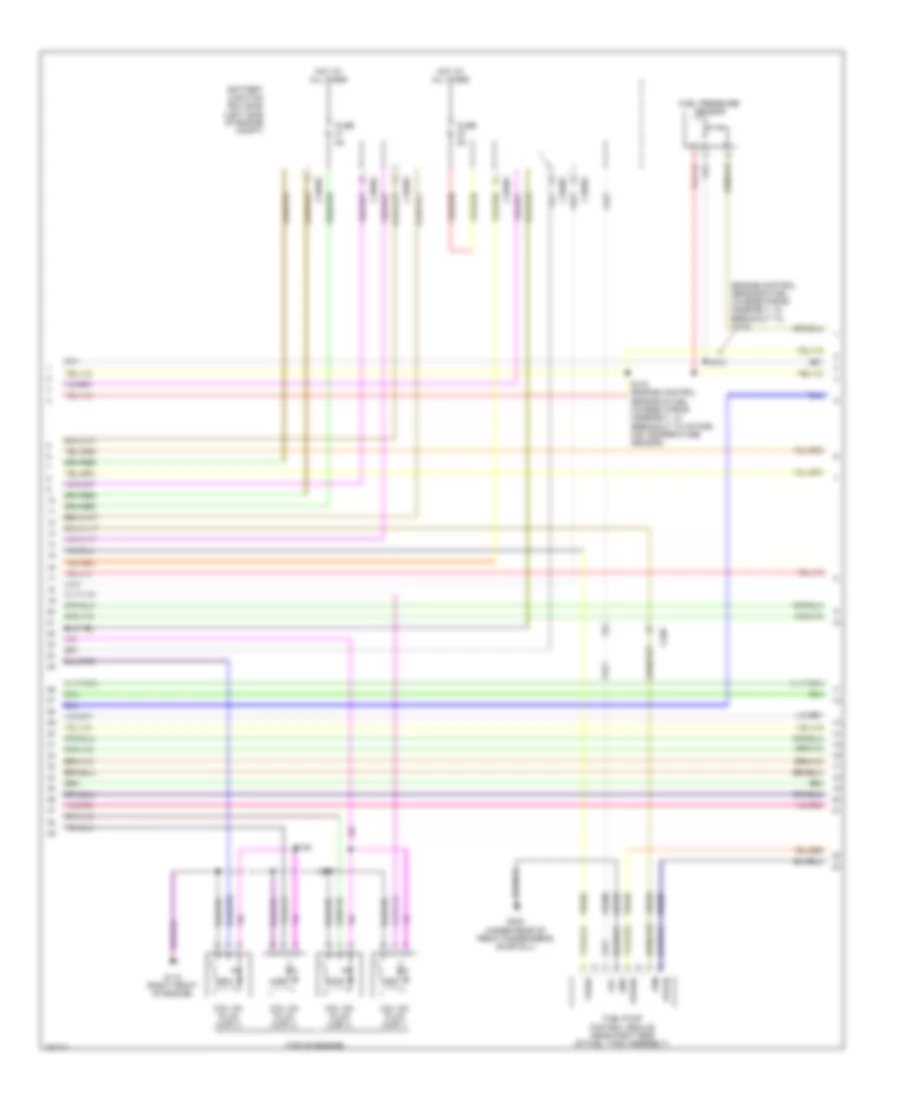
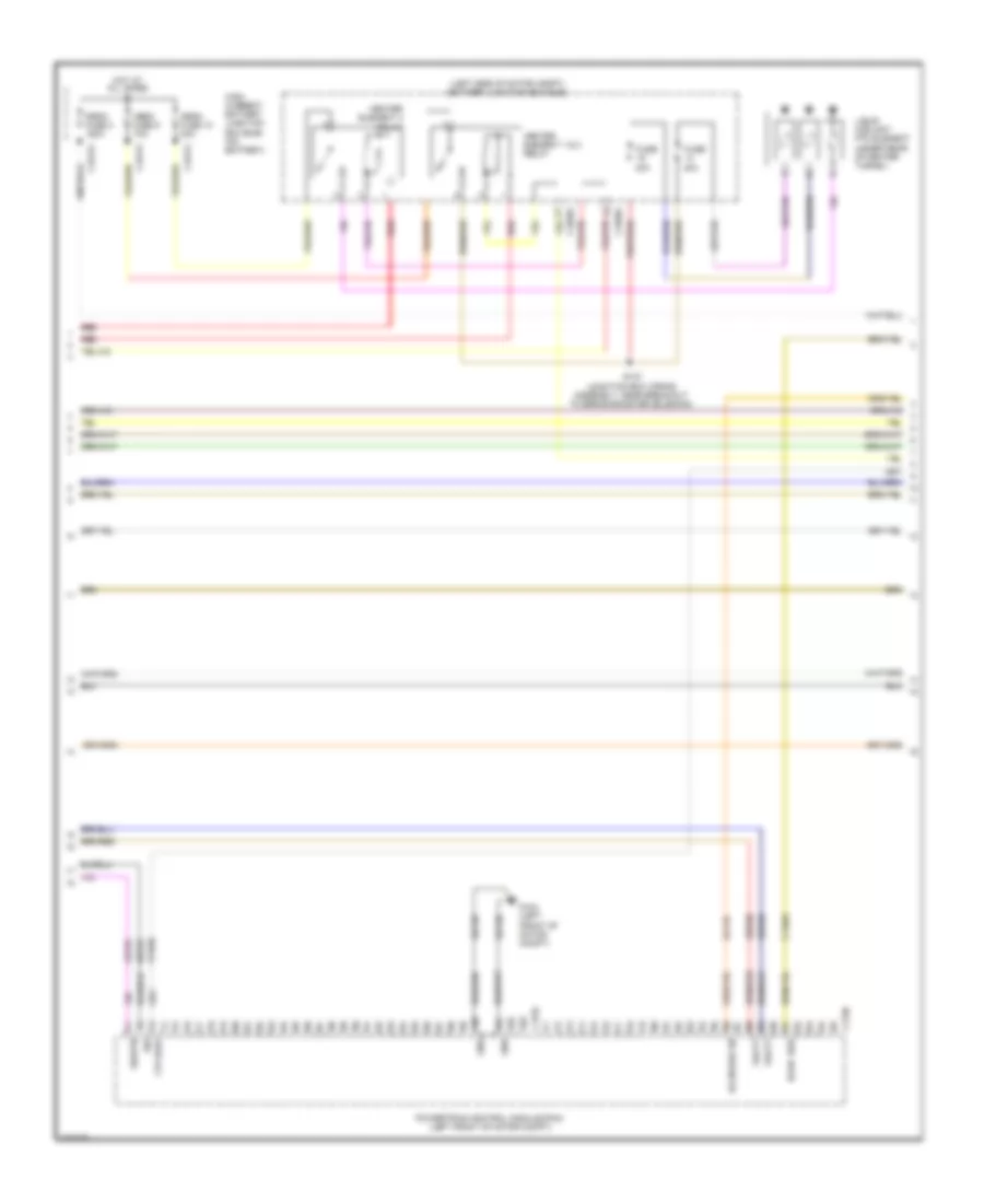
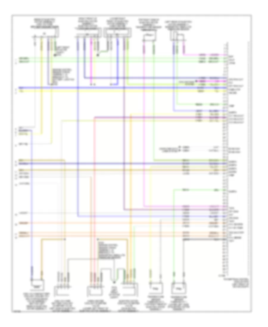
2.0L, Engine Performance Wiring Diagram (3 of 6) for Ford Focus S 2014
List of elements for 2.0L, Engine Performance Wiring Diagram (3 of 6) for Ford Focus S 2014:
- (body wiring harness, near breakout to body control module) s238
- (integral to front passenger's door outside rearview mirror assembly) ambient air temperature (aat) sensor
- (junction box wiring assembly, near breakout to body control module)
- Body control module (bcm) (lower right side of dash)
- C175e
- C2280a
- C2280b
- C2280c
- C2280e
- Cca29
- Ce113
- Ce205
- Ce207
- Ce303
- Ce304
- Ce305
- Ce306
- Ce412
- Ce436
- Ce501
- Ce508
- Cmp11
- Cmp12
- Computer data lines system
- Cop1a
- Cop2d
- Cop3b
- Cop4c
- Evapcp
- Evaporative emission (evap) purge valve (right rear of engine)
- Event signal
- Fuel pump level gnd
- Fuel pump level sensor
- Fuel pump relay
- Fuse 20a
- Hot at all times
- Hs can+
- Hs can-
- Inj1
- Inj3
- Ks1+
- Ks2+
- Le452
- Micro
- Nca
- Powertrain control module (pcm) (left side of transmission)
- Re143
- Re144
- Right exterior rearview mirror
- Rmc32
- S125 (engine control sensor & fuel charge wiring assembly, in breakout to powertrain control module)
- S251
- Stop light switch
- Tacm+
- Tp2
- Uo2s11
- Uo2shrt11
- Uo2spct11
- Vct11
- Vct12
- Vdb04
- Vdb05
- Ve518
- Ve801
- Ve802
- Ve819
- Ve826
- Ve827
- Vmc11
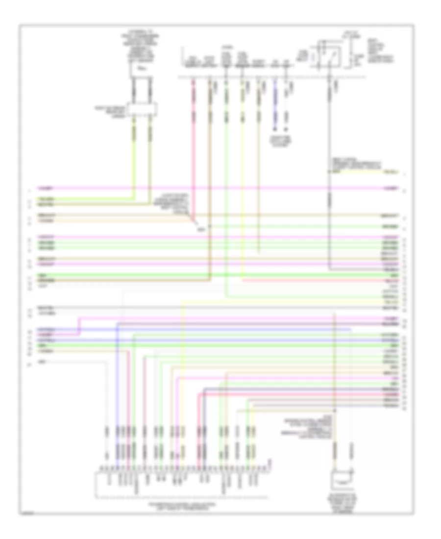
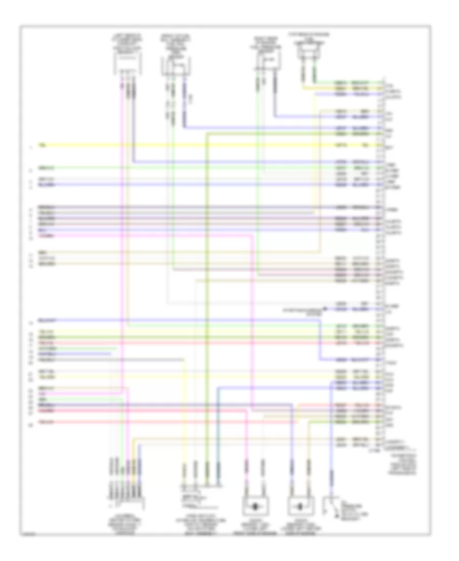
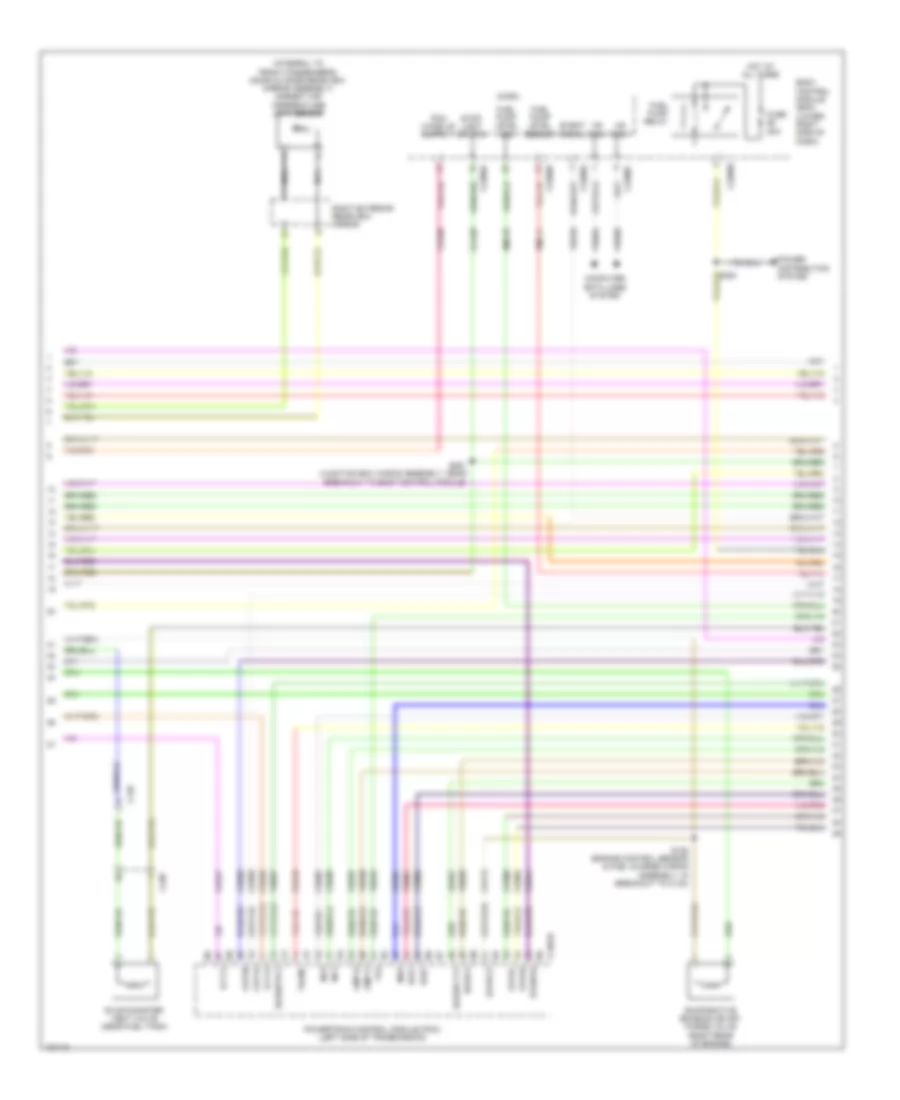
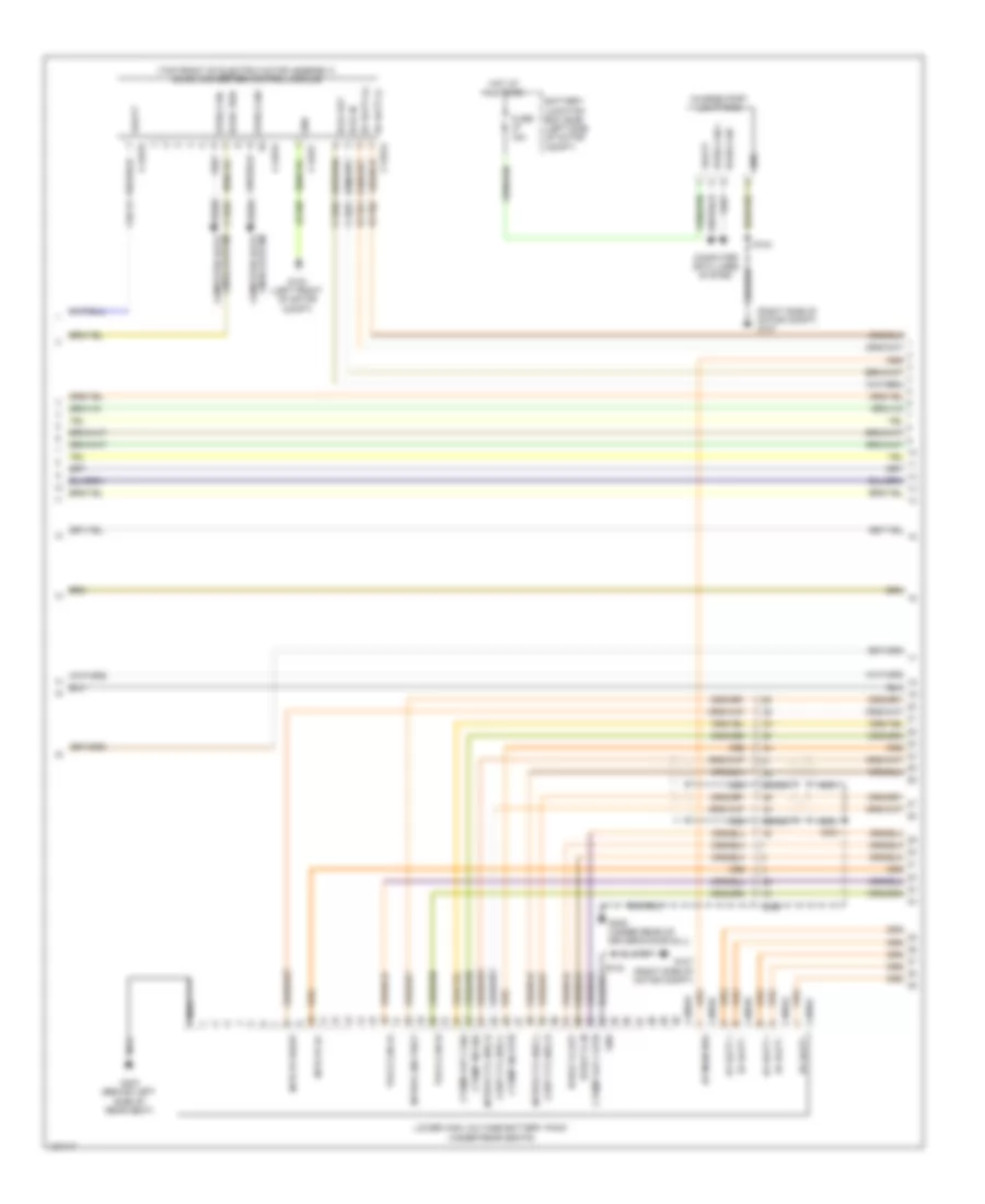
2.0L, Engine Performance Wiring Diagram (4 of 6) for Ford Focus S 2014
List of elements for 2.0L, Engine Performance Wiring Diagram (4 of 6) for Ford Focus S 2014:
- (top of engine)
- Battery junction box (bjb) (left side of engine compt)
- C1035c
- C1750a
- C238
- Cbb42
- Coil on plug (cop) 1
- Coil on plug (cop) 2
- Coil on plug (cop) 3
- Coil on plug (cop) 4
- Fpc
- Fpm
- Fppwr
- Fprtn
- Fuel pump control module (near right side of fuel tank assembly)
- Fuse 5a
- G103 (left rear of engine)
- G304 (under rear of front passenger's door sill)
- Gd152
- Gnd
- Hot at all times
- Re225
- S100
- S117
- Transmission control module (tcm) (left side of transmission)
- Ve208
- Ve225
- Ve518
- Vpwr
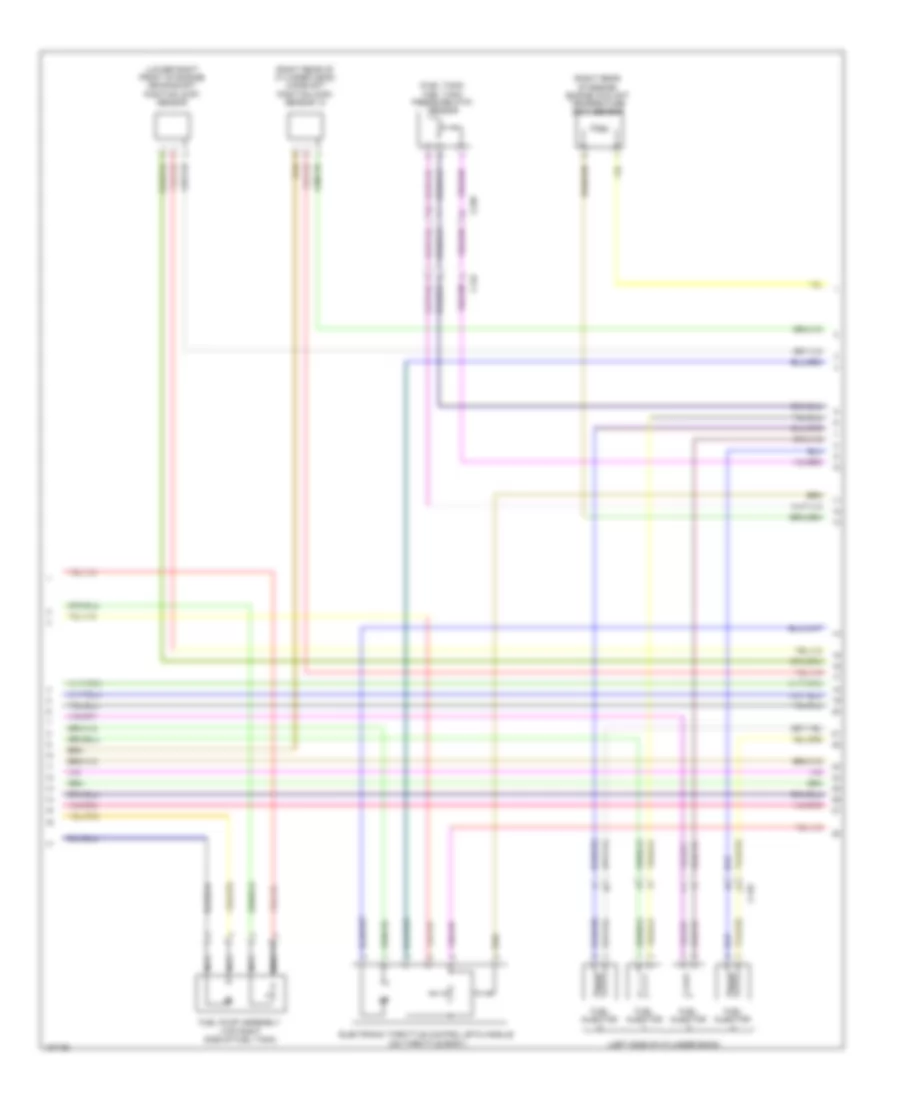
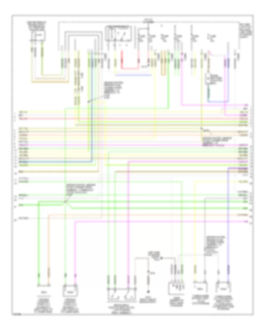
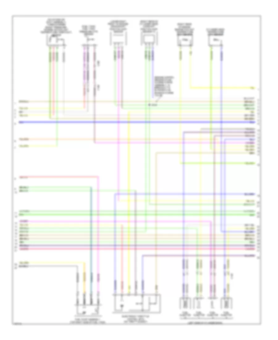
2.0L, Engine Performance Wiring Diagram (5 of 6) for Ford Focus S 2014
List of elements for 2.0L, Engine Performance Wiring Diagram (5 of 6) for Ford Focus S 2014:
- (fuel tank) fuel tank pressure (ftp) sensor
- (left side of cylinder bank)
- (lower right front of engine) crankshaft position (ckp) sensor
- (right rear of cylinder head) camshaft position (cmp) sensor 12
- (right rear of engine) engine coolant temperature (ect) sensor
- C110
- C134
- C238
- Electronic throttle control (etc) module (on throttle body)
- Fuel injector
- Fuel pump assembly (top right side of fuel tank)
- Nca
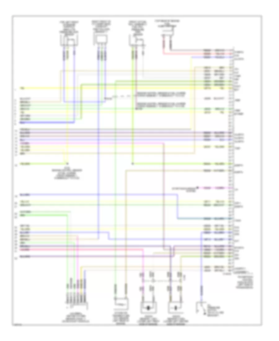
2.0L, Engine Performance Wiring Diagram (6 of 6) for Ford Focus S 2014
List of elements for 2.0L, Engine Performance Wiring Diagram (6 of 6) for Ford Focus S 2014:
- (front of fuel rail assembly) fuel rail pressure (frp) sensor
- (left rear of cylinder head) camshaft position (cmp) sensor 11
- (right rear of engine) fuel pressure sensor
- (top rear of engine)
- C-sigrtn
- C-vref
- C110
- C175e
- Cbb12
- Ce206
- Ce208
- Ce231
- Ce426
- Ce908
- Ckp
- Digital
- E-sigrtn
- E-vref
- Ect
- Etcref
- Etcrtn
- Flp
- Frp
- Ftp
- Fuel injection pump
- Fvr
- Fvrrtn
- Iat
- Inj1rtn
- Inj2
- Inj2rtn
- Inj3rtn
- Inj4
- Inj4rtn
- Knock sensor 1 (ks1) (lower left front side of engine)
- Knock sensor 2 (ks2) (lower left center side of engine)
- Ks1-
- Ks2-
- Le135
- Le143
- Le144
- Le230
- Le238
- Le428
- Le448
- Le451
- Lin
- Maf
- Mass air flow/ intake air temperature (maf/iat) sensor (on air intake duct assembly)
- Nca
- Oil pressure switch (on oil filter bracket)
- Ops
- Powertrain control module (pcm) (left side of transmission)
- Re135
- Re141
- Re205
- Re206
- Re207
- Re208
- Re230
- Re238
- Re323
- Re324
- Re329
- Re427
- Sigrtn
- Starting/charging system
- Tacm-
- Tp1
- Universal heated oxygen sensor (ho2s) 11 (on exhaust manifold)
- Uo2sgref11
- Uo2spc11
- Vdc46
- Ve706
- Ve707
- Ve711
- Ve716
- Ve727
- Ve803
- Ve804
- Ve818
- Ve922
- Vpref
- Vref
- Vref 5v
2.0L FLEX FUEL
2.0L Flex Fuel, Engine Performance Wiring Diagram (1 of 6) for Ford Focus S 2014
List of elements for 2.0L Flex Fuel, Engine Performance Wiring Diagram (1 of 6) for Ford Focus S 2014:
- (in exhaust, downstream of catalytic converter) heated oxygen sensor (ho2s) 12
- (or ce903)
- 10a
- Aat
- Acceleration pedal position (app) sensor (top of accelerator pedal assembly)
- Accr
- Acpt
- Air conditioning system starting/charging system
- App1
- App2
- Apprtn1
- Apprtn2
- Appvref1
- Appvref2
- Battery junction box (bjb) (left side of engine compt)
- Bpp
- Bps
- C-sigrtn
- C-vref
- C1035c
- C134
- C1750a
- C175b
- Canv
- Cbb08
- Cbb42
- Cca29
- Ccb08
- Cdc12
- Cdc26
- Ce112
- Ce233
- Ce302
- Ce436
- Cet47
- Ch109
- Clth pdl sw
- Computer data lines system
- Cooling fans system
- Cpp (or p/n sw)
- Crank detect
- Cruise control system
- Ens
- Exterior lights system
- Fcv
- Fpc
- Fpm
- From pcm
- Fuse
- Fuse 15a
- G104 (left side of engine compt)
- Gd120
- Ho2s12
- Hot w/ ignition relay energized
- Hs can+
- Hs can-
- Htr12
- Instrument panel cluster (ipc)
- Isp-r
- Le136
- Le137
- Lh108
- Ms can+
- Ms can-
- Nca
- Pcmrc
- Power distribution system
- Power relay (diagram 2 of 6)
- Powertrain control module (pcm) (left side of transmission)
- Pwr gnd
- Re136
- Re137
- Re242
- Reversed gear sw
- Rh107
- Rh108
- S113
- Sigrtn
- Smc
- Smcs
- Starting/ charging system
- Starting/charging system
- Transmission control module (tcm) (left side of transmission)
- Up wake
- Vdb04
- Vdb05
- Ve203
- Ve208
- Ve518
- Ve701
- Ve702
- Ve731
- Vh407
- Vh442
- Vpwr
- Wake up
2.0L Flex Fuel, Engine Performance Wiring Diagram (2 of 6) for Ford Focus S 2014
List of elements for 2.0L Flex Fuel, Engine Performance Wiring Diagram (2 of 6) for Ford Focus S 2014:
- (center rear of engine compt) a/c pressure transducer
- (engine control sensor & fuel charge wiring assembly, near breakout to variable camshaft timing solenoid 11) s114
- A10
- Battery junction box (bjb) (left side of engine compt)
- Brake pedal position (bpp) switch (top of brake pedal assembly)
- C1035b
- C1035c
- C134
- C238
- C340
- Diode (battery junction box)
- Evap canister vent valve (near fuel tank)
- Fuse
- Fuse 10a
- Fuse 30a
- G107 (right side of engine compt)
- Hot at all times
- Ignition relay
- Pcm power relay
- Red
- S104
- S115
- To fuse 32 diagram (1 of 6)
- Variable camshaft timing (vct) solenoid 11 (left front of cylinder head)
- Variable camshaft timing (vct) solenoid 12 (right front of cylinder head)
2.0L Flex Fuel, Engine Performance Wiring Diagram (3 of 6) for Ford Focus S 2014
List of elements for 2.0L Flex Fuel, Engine Performance Wiring Diagram (3 of 6) for Ford Focus S 2014:
- (body wiring harness, near breakout to body control module) s238
- (integral to front passenger's door outside rearview mirror assembly) ambient air temperature (aat) sensor
- (junction box wiring assembly, near breakout to body control module)
- Body control module (bcm) (lower right side of dash)
- C175e
- C2280a
- C2280b
- C2280c
- C2280e
- Cca29
- Ce113
- Ce205
- Ce207
- Ce303
- Ce304
- Ce305
- Ce306
- Ce412
- Ce436
- Ce501
- Ce508
- Cmp11
- Cmp12
- Computer data lines system
- Cop1a
- Cop2d
- Cop3b
- Cop4c
- Evapcp
- Evaporative emission (evap) purge valve (right rear of engine)
- Event signal
- Fuel pump level gnd
- Fuel pump level sensor
- Fuel pump relay
- Fuse 20a
- Hot at all times
- Hs can+
- Hs can-
- Inj1
- Inj3
- Ks1+
- Ks2+
- Le452
- Micro
- Nca
- Powertrain control module (pcm) (left side of transmission)
- Re143
- Re144
- Right exterior rearview mirror
- Rmc32
- S125 (engine control sensor & fuel charge wiring assembly, in breakout to powertrain control module)
- S251
- Stop light switch
- Tacm+
- Tp2
- Uo2s11
- Uo2shrt11
- Uo2spct11
- Vct11
- Vct12
- Vdb04
- Vdb05
- Ve518
- Ve801
- Ve802
- Ve819
- Ve826
- Ve827
- Vmc11
2.0L Flex Fuel, Engine Performance Wiring Diagram (4 of 6) for Ford Focus S 2014
List of elements for 2.0L Flex Fuel, Engine Performance Wiring Diagram (4 of 6) for Ford Focus S 2014:
- (top of engine)
- Battery junction box (bjb) (left side of engine compt)
- C1035c
- C1750a
- C238
- Cbb42
- Coil on plug (cop) 1
- Coil on plug (cop) 2
- Coil on plug (cop) 3
- Coil on plug (cop) 4
- Fpc
- Fpm
- Fppwr
- Fprtn
- Fuel pump control module (near right side of fuel tank assembly)
- Fuse 5a
- G103 (left rear of engine)
- G304 (under rear of front passenger's door sill)
- Gd152
- Gnd
- Hot at all times
- Re225
- S100
- S117
- Transmission control module (tcm) (left side of transmission)
- Ve208
- Ve225
- Ve518
- Vpwr
2.0L Flex Fuel, Engine Performance Wiring Diagram (5 of 6) for Ford Focus S 2014
List of elements for 2.0L Flex Fuel, Engine Performance Wiring Diagram (5 of 6) for Ford Focus S 2014:
- (fuel tank) fuel tank pressure (ftp) sensor
- (left side of cylinder bank)
- (lower right front of engine) crankshaft position (ckp) sensor
- (right rear of cylinder head) camshaft position (cmp) sensor 12
- (right rear of engine) engine coolant temperature (ect) sensor
- C110
- C134
- C238
- Electronic throttle control (etc) module (on throttle body)
- Fuel injector
- Fuel pump assembly (top right side of fuel tank)
- Nca
2.0L Flex Fuel, Engine Performance Wiring Diagram (6 of 6) for Ford Focus S 2014
List of elements for 2.0L Flex Fuel, Engine Performance Wiring Diagram (6 of 6) for Ford Focus S 2014:
- (front of fuel rail assembly) fuel rail pressure (frp) sensor
- (left rear of cylinder head) camshaft position (cmp) sensor 11
- (right rear of engine) fuel pressure sensor
- (top rear of engine)
- C-sigrtn
- C-vref
- C110
- C175e
- Cbb12
- Ce206
- Ce208
- Ce231
- Ce426
- Ce908
- Ckp
- Digital
- E-sigrtn
- E-vref
- Ect
- Etcref
- Etcrtn
- Flp
- Frp
- Ftp
- Fuel injection pump
- Fvr
- Fvrrtn
- Iat
- Inj1rtn
- Inj2
- Inj2rtn
- Inj3rtn
- Inj4
- Inj4rtn
- Knock sensor 1 (ks1) (lower left front side of engine)
- Knock sensor 2 (ks2) (lower left center side of engine)
- Ks1-
- Ks2-
- Le135
- Le143
- Le144
- Le230
- Le238
- Le428
- Le448
- Le451
- Lin
- Maf
- Mass air flow/ intake air temperature (maf/iat) sensor (on air intake duct assembly)
- Nca
- Oil pressure switch (on oil filter bracket)
- Ops
- Powertrain control module (pcm) (left side of transmission)
- Re135
- Re141
- Re205
- Re206
- Re207
- Re208
- Re230
- Re238
- Re323
- Re324
- Re329
- Re427
- Sigrtn
- Starting/charging system
- Tacm-
- Tp1
- Universal heated oxygen sensor (ho2s) 11 (on exhaust manifold)
- Uo2sgref11
- Uo2spc11
- Vdc46
- Ve706
- Ve707
- Ve711
- Ve716
- Ve727
- Ve803
- Ve804
- Ve818
- Ve922
- Vpref
- Vref
- Vref 5v
2.0L TURBO
2.0L Turbo, Engine Performance Wiring Diagram (1 of 6) for Ford Focus S 2014
List of elements for 2.0L Turbo, Engine Performance Wiring Diagram (1 of 6) for Ford Focus S 2014:
- (in exhaust, downstream of catalytic converter) heated oxygen sensor (ho2s) 12
- Aat
- Acceleration pedal position (app) sensor (top of accelerator pedal assembly)
- Accr
- Acpt
- Air conditioning system
- App1
- App2
- Apprtn1
- Apprtn2
- Appvref1
- Appvref2
- Battery junction box (bjb) (left side of engine compt)
- Bpp
- Bps
- C-sigrtn
- C-vref
- C1035c
- C1381b
- C139
- Canv
- Cbb08
- Cca29
- Ccb08
- Cdc12
- Ce114
- Ce233
- Ce302
- Ce341
- Ce436
- Ce470
- Ce471
- Ce903
- Cet47
- Ch109
- Clth pdl sw
- Computer data lines system
- Cooling fans system
- Cpp (or p/n sw)
- Crank detect
- Cruise control system
- Ens
- Exterior lights system
- Fcv
- Fpc
- Fpm
- Fuse 15a
- G104 (left side of engine compt)
- Gd120
- Ho2s12
- Hot w/ ignition relay energized
- Hs can+
- Hs can-
- Htr12
- Instrument panel cluster (ipc)
- Isp-r
- Le136
- Le137
- Le238
- Lh108
- Ms can+
- Ms can-
- Nca
- Pcmrc
- Powertrain control module (pcm) (left side of transmission)
- Pwr gnd
- Re136
- Re137
- Re407
- Reversed gear sw
- Rh107
- Rh108
- Sbb10
- Sigrtn
- Smc
- Smcs
- Ssc ctrl
- Ssc monitor
- Starting/charging system
- Vbatt
- Vdb04
- Vdb05
- Ve203
- Ve208
- Ve424
- Ve518
- Ve701
- Ve702
- Ve731
- Vh407
- Vpwr
- Wake up
2.0L Turbo, Engine Performance Wiring Diagram (2 of 6) for Ford Focus S 2014
List of elements for 2.0L Turbo, Engine Performance Wiring Diagram (2 of 6) for Ford Focus S 2014:
- (center rear of engine compt) a/c pressure transducer
- (engine control sensor & fuel charge wiring assembly, in breakout to c139) s128
- (engine control sensor & fuel charge wiring assembly, in breakout to coil on plug 4) s135
- (engine control sensor & fuel charge wiring assembly, in breakout to coil on plug 4) s136
- (engine control sensor & fuel charge wiring assembly, in breakout to g104)
- (left side of engine compt) g104
- A10
- Battery junction box (bjb) (left side of engine compt)
- Brake pedal position (bpp) switch (top of brake pedal assembly)
- C1035c
- C238
- C340
- Diode (battery junction box)
- Fuse
- Fuse 10a
- Fuse 30a
- G107 (right side of engine compt)
- Gnd
- Hot at all times
- Noise generator (right rear of engine)
- Out
- Pcm power relay
- Red
- S104
- S115
- S127
- Turbocharge (tc) wastegate regulating valve solenoid (lower right side of engine)
- Turbocharge bypass (tcby) valve (top of engine)
- Variable camshaft timing (vct) solenoid 11 (left front of cylinder head)
- Variable camshaft timing (vct) solenoid 12 (right front of cylinder head)
- Vpwr
2.0L Turbo, Engine Performance Wiring Diagram (3 of 6) for Ford Focus S 2014
List of elements for 2.0L Turbo, Engine Performance Wiring Diagram (3 of 6) for Ford Focus S 2014:
- (integral to front passenger's door outside rearview mirror assembly) ambient air temperature (aat) sensor
- Body control module (bcm) (lower right side of dash)
- C1381e
- C139
- C2280a
- C2280b
- C2280c
- C2280e
- C238
- Cca29
- Ce113
- Ce205
- Ce207
- Ce303
- Ce304
- Ce305
- Ce306
- Ce412
- Ce421
- Ce422
- Ce436
- Ce844
- Cmp11
- Cmp12
- Computer data lines system
- Cop1a
- Cop2d
- Cop3b
- Cop4c
- Evap canister vent valve (near fuel tank)
- Evapcp
- Evaporative emission (evap) purge valve (right rear of engine)
- Event signal
- Fuel pump level gnd
- Fuel pump level sensor
- Fuel pump relay
- Fuse 20a
- Hot at all times
- Hs can+
- Hs can-
- Inj1
- Inj3
- Ks1+
- Ks2+
- Le329
- Le452
- Map
- Micro
- Nca
- Power distribution system
- Powertrain control module (pcm) (left side of transmission)
- Right exterior rearview mirror
- Rmc32
- S125 (engine control sensor & fuel charge wiring assembly, in breakout to c133)
- S251 (junction box wiring assembly, near breakout to body control module)
- Stop light switch
- Tacm+
- Tcwrvs
- Tp2
- Uo2s11
- Uo2shtr11
- Uo2spct11
- Vct11
- Vct12
- Vdb04
- Vdb05
- Ve518
- Ve706
- Ve707
- Ve801
- Ve802
- Ve819
- Ve826
- Ve827
- Vmc11
2.0L Turbo, Engine Performance Wiring Diagram (4 of 6) for Ford Focus S 2014
List of elements for 2.0L Turbo, Engine Performance Wiring Diagram (4 of 6) for Ford Focus S 2014:
- (engine control sensor & fuel charge wiring assembly, in breakout to c133)
- (top of engine)
- Battery junction box (bjb) (left side of engine compt)
- C1035c
- C238
- Coil on plug (cop) 1
- Coil on plug (cop) 2
- Coil on plug (cop) 3
- Coil on plug (cop) 4
- Fpc
- Fpm
- Fppwr
- Fprtn
- Fuel pressure sensor
- Fuel pump control module (near right side of fuel tank assembly)
- Fuse 5a
- G110 (right front of engine)
- G304 (under rear of front passenger's door sill)
- Gd152
- Gnd
- Hot at all times
- Re225
- S131
- S133 (engine control sensor & fuel charge wiring assembly, in breakout to intake air temperature sensor)
- S137
- S138
- Ve208
- Ve225
- Ve518
- Vpwr
2.0L Turbo, Engine Performance Wiring Diagram (5 of 6) for Ford Focus S 2014
List of elements for 2.0L Turbo, Engine Performance Wiring Diagram (5 of 6) for Ford Focus S 2014:
- (engine control sensor & fuel charge wiring assembly, in breakout to evaporative emission purge valve)
- (fuel tank) fuel tank pressure (ftp) sensor
- (left side of cylinder bank)
- (lower right front of engine) crankshaft position (ckp) sensor
- (on intake air duct assembly) turbocharger boost pressure/ charge air coolant temperature (tcbp/cact) sensor
- (right rear of cylinder head) camshaft position (cmp) sensor 12
- (right rear of engine) engine coolant temperature (ect) sensor
- C139
- C145
- C238
- Cylinder head temperature (cht) sensor
- Electronic throttle control (etc) (on throttle body)
- Fuel injector
- Fuel pump assembly (top right side of fuel tank)
- Nca
- S134
2.0L Turbo, Engine Performance Wiring Diagram (6 of 6) for Ford Focus S 2014
List of elements for 2.0L Turbo, Engine Performance Wiring Diagram (6 of 6) for Ford Focus S 2014:
- (engine control sensor & fuel charge wiring assembly, in breakout to c133)
- (engine control sensor & fuel charge wiring assembly, in breakout to c139) s128
- (front of fuel rail assembly) fuel rail pressure (frp) sensor
- (right front of cylinder head) camshaft position (cmp) sensor 11
- (top left front of engine) manifold absolute pressure (map) sensor
- (top rear of engine)
- C1381e
- C145
- Cact
- Ce167
- Ce206
- Ce208
- Ce226
- Ce426
- Ce908
- Cht
- Ckp +
- Ect
- Etcref
- Etcrtn
- Flp
- Frp
- Ftp
- Fuel injection pump
- Fvr
- Fvrrtn
- Iat
- Inj1rtn
- Inj2
- Inj2rtn
- Inj3rtn
- Inj4
- Inj4rtn
- Intake air temperature (iat) sensor (left rear of engine)
- Knock sensor 1 (ks1) (lower left front side of engine)
- Knock sensor 2 (ks2) (lower left center side of engine)
- Ks1-
- Ks2-
- Le134
- Le423
- Le448
- Le451
- Le458
- Lin
- Nca
- Oil pressure switch (on oil filter bracket)
- Ops
- Powertrain control module (pcm) (left side of transmission)
- Re134
- Re205
- Re206
- Re207
- Re208
- Re226
- Re323
- Re324
- Re329
- Re405
- Re454
- S130
- S132 (engine control sensor & fuel charge wiring assembly, in breakout to c133)
- Sigrtn
- Starting/charging system
- Tacm-
- Tcbp
- Tcby
- Tp1
- Universal heated oxygen sensor (ho2s) 11 (on exhaust manifold)
- Uo2sgref11
- Uo2spc11
- Vdn08
- Ve711
- Ve712
- Ve716
- Ve727
- Ve761
- Ve804
- Ve805
- Ve818
- Ve922
- Vref
ELECTRIC
Electric, Engine Performance Wiring Diagram (1 of 7) for Ford Focus S 2014
List of elements for Electric, Engine Performance Wiring Diagram (1 of 7) for Ford Focus S 2014:
- (brake pedal support bracket) brake pedal position switch
- (junction box wiring assembly, near breakout to body control module)
- (left side of motor compt) battery junction box (bjb)
- 12v wake up
- A/c high pressure sensor (left front side of electric motor assembly)
- Ac sol lsd
- Accelerator pedal position sensor (top of accelerator pedal assembly)
- Achp
- Anti-lock brakes system
- App
- App2
- Apprtn
- Apprtn2
- Appvref
- Appvref2
- Battery junction box (bjb) (left side of motor compt)
- Body control module (lower right side of dash)
- Bpp
- Bps
- C1035c
- C175a
- C2280a
- C2280c
- Cbb24
- Cbp04
- Cca29
- Ccb08
- Ccb29
- Ccb30
- Ccs05
- Cdc35
- Ce238
- Ce302
- Ce436
- Cet25
- Cet70
- Chiller sol
- Computer data lines system
- Cont disable
- Cont sens
- Cp3 pwm out
- Crank detect
- Cv2 div fdbk
- Cv3 div fdbk
- Cyb01
- Cyb02
- Fuse 5a
- G105 (left side of motor compt)
- G107 (right side of motor compt)
- Gnd
- He3rc
- Hot at all times
- Hot w/ ignition relay energized
- Hs can+
- Hs can-
- Le126
- Le137
- Let56
- Let57
- Lh108
- Micro
- Pcm wake up sply
- Pcmrc
- Power distribution system
- Powertrain control module (pcm) (left front of motor compt)
- Ptc hsd en
- Re136
- Re137
- Ret56
- Rh108
- S102
- S104
- S251
- Sig
- Sigrtn
- Stop light sw
- Vac pump
- Vacrc
- Vasp
- Vdb04
- Vdb05
- Vdc46
- Ve701
- Ve702
- Vehicle audible signal for pedestrian (left front of motor compt)
- Vet56
- Vh422
- Vpwr
- Vref
- Vyb30
- Vyb32
- Wake up
- Wake up pcm
Electric, Engine Performance Wiring Diagram (2 of 7) for Ford Focus S 2014
List of elements for Electric, Engine Performance Wiring Diagram (2 of 7) for Ford Focus S 2014:
- (left side of motor compt) battery junction box (bjb)
- 10a
- 15a
- 20a
- 5v 1
- 5v 2
- C1035c
- C238
- Cabin air conditioning isolator solenoid valve (right side of motor compt)
- Computer data lines system
- Contactor relay
- Engine cooling fan relay
- Fuse
- Fuse 10a
- Fuse 15a
- Fuse 40a
- Fuse 5a
- Gear neutral sensor (top of transmission)
- Gnd 1
- Gnd 2
- Hot at all times
- Hot w/ ign relay energized
- Instrument panel cluster (ipc)
- Ms can+
- Ms can-
- Pcm power relay
- Power distribution system
- Red
- S115
- S131
- S151
- Sig 1
- Sig 2
Electric, Engine Performance Wiring Diagram (3 of 7) for Ford Focus S 2014
List of elements for Electric, Engine Performance Wiring Diagram (3 of 7) for Ford Focus S 2014:
- (left side of motor compt) battery junction box (bjb)
- 40a
- Bccm hsd en
- C1035c
- C1617c
- C1617f
- C1617l
- C175a
- C175b
- Cp3 diag
- Cyd03
- Dc/dc hsd
- Fuse
- G104 (left front of motor compt)
- Gd120
- Gnd
- Heater element 1 & 2 relay
- Heater element 3 relay
- High current battery junction box (bjb) (on battery)
- Hot at all times
- Liquid coolant ptc element (under rear of center tunnel)
- Mega fuse 10 40a
- Mega fuse 2 150a
- Mega fuse 5 70a
- Powertrain control module (pcm) (left front of motor compt)
- Red
- Ret57
- S137 (junction box wiring assembly, near breakout to brake booster solenoid)
- Sbb30
- Sig
- Sigrtn
- Vbatt
- Vet57
- Vyb30
- Za116
Electric, Engine Performance Wiring Diagram (4 of 7) for Ford Focus S 2014
List of elements for Electric, Engine Performance Wiring Diagram (4 of 7) for Ford Focus S 2014:
- (right side of motor compt) g107
- (top front of electric motor assembly) dc/dc converter control module
- 15a
- Battery junction box (bjb) (left side of motor compt)
- C1457a
- C1457b
- C1457c
- C1457d
- C238
- C4804a
- C4804b
- C4804c
- C4804d
- C4804e
- Cdc13
- Charge port light ring
- Computer data lines system
- Ctemp in2 rtn
- Ctemp in2 sig
- Ctemp out 2 rtn
- Ctemp out 2 sig
- Cyd01
- Cyd02
- Cyd03
- Dc/dc hsd
- Evhs can +
- Evhs can -
- Evhs can+
- Evhs can-
- Fuse
- G103 (left front of motor compt)
- G107 (right side of motor compt)
- G305 (under rear of driver's door sill)
- G403 (behind left side of rear seat)
- Gnd
- Hot at all times
- Hv batt (+)
- Hv batt (-)
- Hv batt +
- Hv batt -
- Hvbat il in
- Hvbat il out
- Hvil in
- Hvil out
- Hyt01
- Hyt02
- Intr pk b+
- Intr pk wkup
- Intrpk 2nd prot
- Lines system computer data
- Lower high voltage battery pack (under rear seats)
- Nca
- Pack can hi
- Pack can lo
- S104
- S421
- Vbatt
- Vdb04
- Vdb05
- Za180
Electric, Engine Performance Wiring Diagram (5 of 7) for Ford Focus S 2014
List of elements for Electric, Engine Performance Wiring Diagram (5 of 7) for Ford Focus S 2014:
- (left side of electric motor assembly) air conditioning control module
- (main wiring assembly, near breakout to right footwell air discharge temperature sensor)
- 12v bccm bcem
- 12v pcm becm
- 12v wake up
- 20a
- 40a
- Becm pcmp
- Body control module (lower right side of dash)
- C1822a
- C1822b
- C1822c
- C1822d
- C1822e
- C1822f
- C1822g
- C1822h
- C2280c
- C237
- C238
- C310a
- C4805a
- C4805b
- C4805c
- C4805d
- C4805e
- Ce436
- Computer data lines system
- Cr115
- Ctemp in2 rtn
- Ctemp in2 sig
- Ctemp out 2 rtn
- Ctemp out 2 sig
- Cyd01
- Cyd02
- Ens
- Ev hs can +
- Ev hs can -
- Ev hs can+
- Ev hs can-
- Event sig
- Front fuse
- G305 (under rear of driver's door sill)
- G404 (under right side of rear seats)
- Gnd
- Hdc52
- Hdc53
- Hv batt +
- Hv batt -
- Hv main pos
- Hv+
- Hv-
- Hvbat il in
- Hvbat il out
- Hvil
- Hyt01
- Hyt02
- Intr pk b+
- Intr pk wkup
- Intrpk 2nd prot
- Micro
- Middle fuse
- Nca
- Pack can hi
- Pack can lo
- Pcm shutoff
- Rear fuse
- Restraints control module (under center console)
- S280
- S415
- S421
- Transmission control module (top of electric motor assembly)
- Upper high voltage battery pack (behind rear seats)
- Vbatt
- Vdb04
- Vdb05
- Za103
- Za113
- Za114
Electric, Engine Performance Wiring Diagram (6 of 7) for Ford Focus S 2014
List of elements for Electric, Engine Performance Wiring Diagram (6 of 7) for Ford Focus S 2014:
- (above left front wheelwell) inline fuse 1
- (above left front wheelwell) inline fuse 2
- (lower left front side of electric motor assembly) a/c low pressure sensor
- 12v en
- 12v psr o/p
- 40a
- 50a
- A10
- Ac line 1
- Ac line 2
- Ambient air temperature sensor (in right exterior rearview mirror assembly)
- Battery charging control module (under left front of vehicle)
- Battery junction box (bjb) (left side of motor compt)
- C1035c
- C1821a
- C1821b
- C1821c
- C1824
- C238
- C340
- C626
- Charge port (above left front wheelwell)
- Computer data lines system
- Cyb55
- Cyb56
- Evhs can +
- Evhs can -
- Fuse
- G104 (left front of motor compt)
- G111 (right rear of electric motor assembly)
- G112 (rear of left front wheelwell)
- G113 (right front of electric motor assembly)
- Gnd
- Hot at all times
- Hv batt (+)
- Hv batt (-)
- Hv batt +
- Hv batt -
- Hyb51
- Hyb52
- Hyb53
- Hyb54
- Nca
- Pilot
- Pmw ctrl
- Prox
- Prox resistor (at charge port)
- Ptc heater (front of electric motor assembly)
- Rear junction box (rjb) (behind rear of left rear quarterpanel)
- Ryb57
- Vbatt
- Vdb04
- Vdb05
- Wack up
- Za116
- Za150
- Za259
Electric, Engine Performance Wiring Diagram (7 of 7) for Ford Focus S 2014
List of elements for Electric, Engine Performance Wiring Diagram (7 of 7) for Ford Focus S 2014:
- (engine control sensor wiring assembly, in breakout to battery junction box) s150
- (left front of motor compt) g104
- (left rear of electric motor assembly) barometric absolute pressure sensor
- (lower right front of electric motor assembly) cabin heater coolant pump
- (rear of electric motor assembly) high voltage battery coolant pump
- (right front of electric motor assembly) electric motor coolant pump
- (top right side of electric motor assembly) temperature sensor thermostat 2
- Aat
- Aclp
- Bap
- C175b
- Cabin heater coolant diverter valve (lower left front of electric motor assembly)
- Cabin htr
- Cbb12
- Ce321
- Chp01
- Computer data lines system
- Cooling fans system
- Cp1 diag
- Cp1 pwm out
- Cp2 diag
- Cp2 pwm out
- Cv1 anlg out
- Cv1 div fdbk
- Cv2 anlg out
- Cv3 anlg out
- Electric motor coolant diverter valve (on electric motor assembly)
- Evhs can+
- Evhs can-
- Fcv
- G104 (left front of motor compt)
- He12rc
- High voltage battery coolant cooler thv/ isolator solenoid valve assembly (bottom left rear of electric motor assembly)
- High voltage battery coolant diverter valve (left side of electric motor assembly)
- Hvil sense
- Hvil source
- Lh108
- Pcm shutoff in
- Powertrain control module (pcm) (left front of motor compt)
- Re141
- Re238
- Rh107
- Rh108
- S152 (engine control sensor wiring assembly, in breakout to barometric absolute pressure sensor)
- Sigrtn
- Sigtrn
- Temperature sensor thermostat 1 (lower left side of electric motor assembly)
- Temperature sensor thermostat 3 (top right rear of electric motor assembly)
- Tst1
- Tst2
- Tst3
- Vdb04
- Vdb05
- Ve203
- Ve705
- Ve727
- Ve740
- Vh422
- Vmc15
- Vpwr
- Vref
- Vyb30
- Vyb31
- Vyb32
- Za103
- Za113
- Za114

 Čeština
 Dansk
Dansk Deutsch
 Ελληνικά
 English
 English
 Español
 Suomi
Suomi Français
 Français
 עברית
עברית Magyar
 Italiano
 日本語
日本語 한국어
한국어 Nederlands
 Polski
 Português
 Português
 Română
 Русский
 Slovenčina
 Slovenščina
 Svenska
 Türkçe
 中文 (中国)