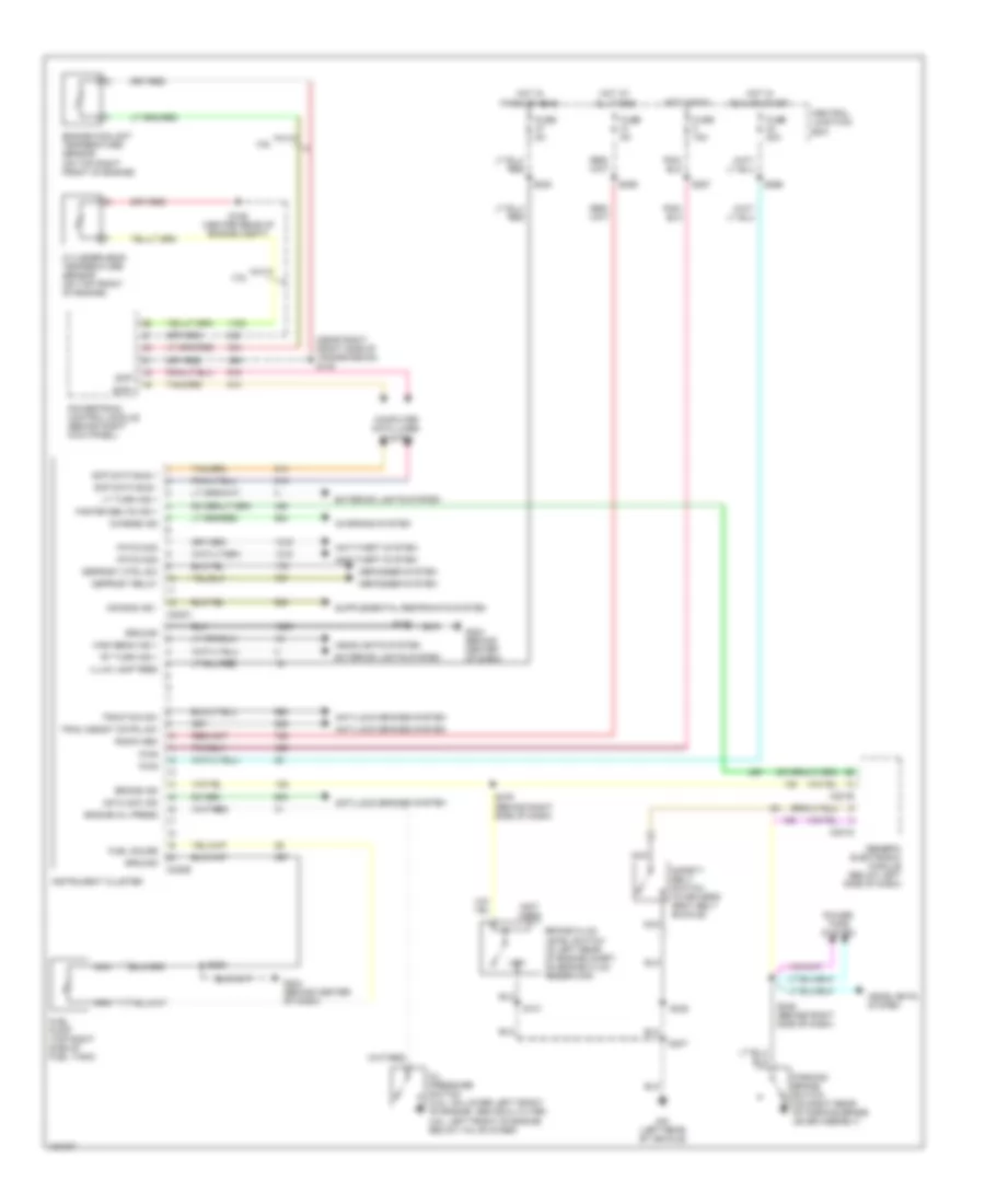
INSTRUMENT CLUSTER
Instrument Cluster Wiring Diagram for Ford Mustang GT Bullitt 2002
List of elements for Instrument Cluster Wiring Diagram for Ford Mustang GT Bullitt 2002:
- (left rear of vehicle)
- (near right front side of transmission) s130
- (not used)
- 3.8l
- 4.6l
- Air bag ind -
- Anti-lock brakes system
- Anti-theft system
- Antilock ind
- Brake fluid level switch (in left rear of engine compt, on brake fluid reservoir)
- Brake ind
- C201d
- C201e
- C220a
- C220b
- Central junction box
- Charge ind
- Charging system
- Computer data lines system
- Cylinder-head temperature sensor (on top front of engine)
- Defogger system
- Defrost ctrl sw
- Defrost relay
- Engine coolant temperature sensor (on top right front of engine)
- Engine oil press
- Exterior lights system
- Fasten belts ind +
- Fuel gauge
- Fuel pump (top right side of fuel tank)
- Fuse 15a
- Fuse 20a
- Fuse 5a
- G204 (behind center of dash)
- Generic electronic module (below left side of dash)
- Ground
- Headlights system
- High beam ind +
- Hot at all times
- Hot in park or head
- Hot in run
- Hot in run or start
- Illum lamp feed
- Instrument cluster
- Low
- Lt turn ind +
- Nca
- Oil pressure switch (3.8l: on lower left front of engine, above oil filter, 4.6l: left front of engine below valve cover)
- Parking brake switch (on right rear of parking brake lever asembly)
- Pats mod
- Power tops system
- Powertrain control module (behind right kick panel)
- Pwr
- Radio mem
- Rt turn ind +
- S101
- S126 (center rear of engine compt)
- S205
- S206
- S230
- S246 (behind right side of dash)
- S257
- S259
- S266
- S276 (behind right side of dash)
- S307
- S322
- Safety belt switch (in driver's seat belt buckle)
- Scp data bus +
- Scp data bus -
- Scp+
- Scp-
- Trac assist cntrl sw
- Traction sw
 Čeština
 Dansk
Dansk Deutsch
 Ελληνικά
 English
 English
 Español
 Suomi
Suomi Français
 Français
 עברית
עברית Magyar
 Italiano
 日本語
日本語 한국어
한국어 Nederlands
 Polski
 Português
 Português
 Română
 Русский
 Slovenčina
 Slovenščina
 Svenska
 Türkçe
 中文 (中国)
 Hrvatski