SHIFT INTERLOCK
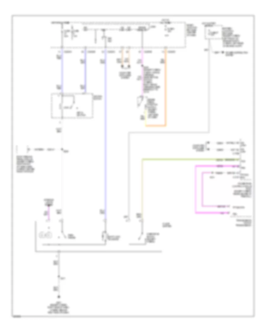
Shift Interlock Wiring Diagram for Mercury Mariner Hybrid 2009
List of elements for Shift Interlock Wiring Diagram for Mercury Mariner Hybrid 2009:
- Battery junction box (bjb) (except hybrid: left front of engine compt) (hybrid: left rear of engine compt)
- Brake pedal position switch (except hybrid: left side of dash)
- Brake pedal sw
- Bs1
- Bs1 fet
- C175t rtn
- C2280a
- C2280b
- C2280c
- C2280d
- Can+
- Can- c175b
- Cdc41
- Cet34
- Computer data lines system
- Floor shifter
- Fuse 10a
- Fuse 2 15a
- Fuse 20a
- Fuse 27 10a
- G201 (except hybrid: right side of dash) (hybrid: behind right end of dash)
- Hot at all times
- Hot in start or run
- Ign sw
- Ignition switch
- Interior lights system
- Key in ignition
- Lock
- Logic
- Ms can+
- Ms can-
- Over/drive switch (except hybrid)
- Park range
- Power distribution system
- Powertrain control module (pcm) (except hybrid) (rear center of firewall)
- Re406
- Roof opening panel module (except hybrid: right front of headliner) (hybrid: center front of roof)
- S121
- S211
- S229
- S308 (except hybrid: in body wiring harness, near key pad switch) (hybrid: body wiring harness, near breakout to c314)
- Shift lock solenoid
- Smart junction box (sjb) (center of dash)
- Tcs
- Tft sig
- Tft sig rtn
- Transmission (top of transmission)
- Trs
- Vdb04
- Vdb05
- Vet32
 Čeština
 Dansk
Dansk Deutsch
 Ελληνικά
 English
 English
 Español
 Suomi
Suomi Français
 Français
 עברית
עברית Magyar
 Italiano
 日本語
日本語 한국어
한국어 Nederlands
 Polski
 Português
 Português
 Română
 Русский
 Slovenčina
 Slovenščina
 Svenska
 Türkçe
 中文 (中国)
 Hrvatski