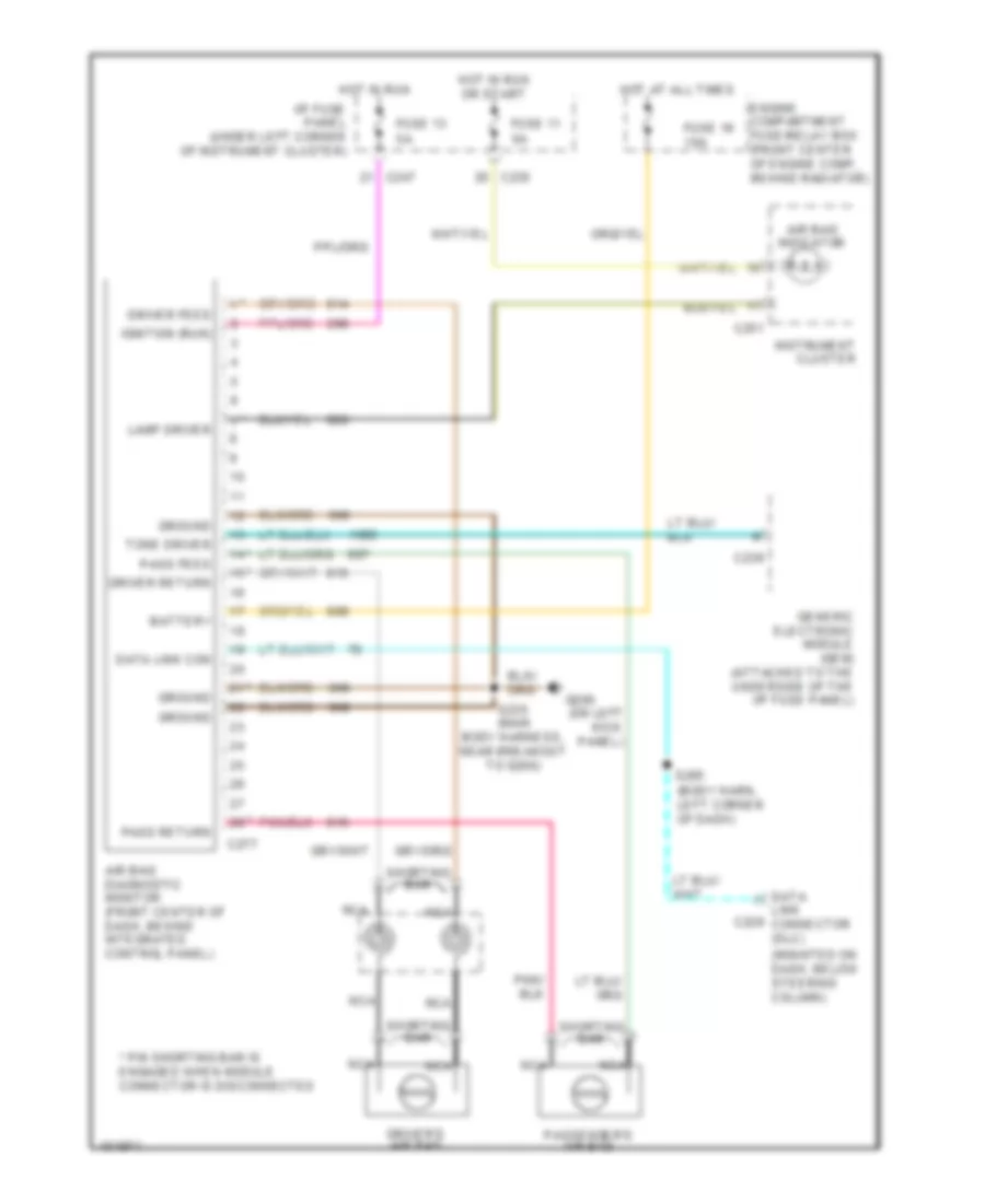
SUPPLEMENTAL RESTRAINTS
Supplemental Restraint Wiring Diagram for Ford Taurus SE 1998
List of elements for Supplemental Restraint Wiring Diagram for Ford Taurus SE 1998:
- (body harn, left corner of dash)
- (mounted on dash, below steering column)
- (on left kick panel)
- * pin shorting bar is engaged when module connector is disconnected
- Air bag diagnostic monitor (front center of dash, behind integrated control panel)
- Air bag indicator
- Battery
- Body harness, near breakout to g200)
- C235
- C236
- C247
- C251
- C277
- Data link c229 connector (dlc)
- Data link con
- Driver feed
- Driver return
- Driver's air bag
- Engine compartment fuse/relay box (front center of engine comp, behind radiator)
- Fuse 11 5a
- Fuse 13 5a
- Fuse 16 10a
- G200
- Generic electronic module (gem) (attached to the underside of the i/p fuse panel)
- Ground
- Hot at all times
- Hot in run
- Hot in run or start
- I/p fuse panel (under left corner of instrument cluster)
- Ignition (run)
- Instrument cluster
- Lamp driver
- Nca
- Pass feed
- Pass return
- Passenger's air bag
- S205
- S235 (main
- Shorting bar
- Tone driver
 Čeština
 Dansk
Dansk Deutsch
 Ελληνικά
 English
 English
 Español
 Suomi
Suomi Français
 Français
 עברית
עברית Magyar
 Italiano
 日本語
日本語 한국어
한국어 Nederlands
 Polski
 Português
 Português
 Română
 Русский
 Slovenčina
 Slovenščina
 Svenska
 Türkçe
 中文 (中国)
 Hrvatski