ANTI-LOCK BRAKES
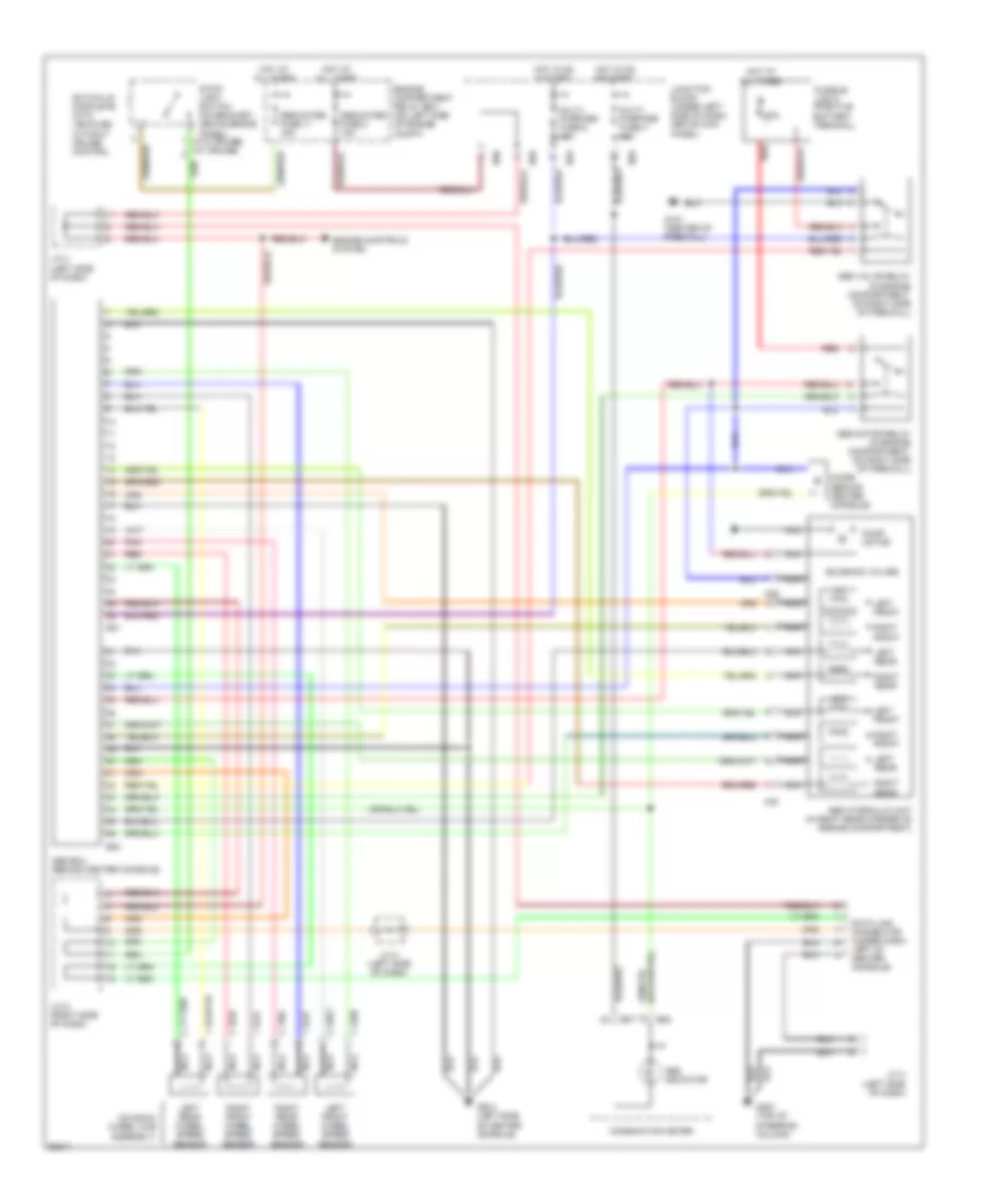
Anti-lock Brake Wiring Diagrams for Mitsubishi Mirage LS 2000
List of elements for Anti-lock Brake Wiring Diagrams for Mitsubishi Mirage LS 2000:
- (on each wheel hub assembly)
- (w/o cruise) (w/ cruise)
- 60a
- A39
- A40
- Abs ecu (behind center console)
- Abs hydraulic unit (in right rear corner of engine compartment)
- Abs indicator
- Abs motor relay (in engine compartment, on right side of firewall)
- Abs valve relay (in engine compartment, on right side of firewall)
- B07
- B08
- B30
- B31
- B60
- B63
- B66
- Combination meter
- Data link connector (under dash, left of center console)
- Dedicated fuse 11 15a
- Dedicated fuse 2 10a
- Diode (behind center console)
- Engine compartment relay box (on left side of engine compt)
- Engine controls system
- Fusible link 8 (positive battery terminal)
- G121 (center of firewall)
- G207 (top of steering column)
- G302 (left side of center console)
- Hot at all times
- Hot in on & start
- Hot in on or start
- J/c 3 (left side of dash)
- J/c 4 (left side of dash)
- J/c 5 (right side of dash)
- Junction block (under left side of dash, above kick panel)
- Left front
- Left front wheel speed sensor
- Left rear
- Left rear wheel speed sensor
- Multi- purpose fuse 4 10a
- Multi- purpose fuse 6 10a
- Nca
- Out
- Pnk
- Pump motor
- Red
- Right front
- Right front wheel speed sensor
- Right rear
- Right rear wheel speed sensor
- Solenoid valves
- Stop- light switch (on bracket, above brake panel)
- Switch is complete with vehicles without cruise control
 Čeština
 Dansk
Dansk Deutsch
 Ελληνικά
 English
 English
 Español
 Suomi
Suomi Français
 Français
 עברית
עברית Magyar
 Italiano
 日本語
日本語 한국어
한국어 Nederlands
 Polski
 Português
 Português
 Română
 Русский
 Slovenčina
 Slovenščina
 Svenska
 Türkçe
 中文 (中国)
 Hrvatski