COOLING FAN
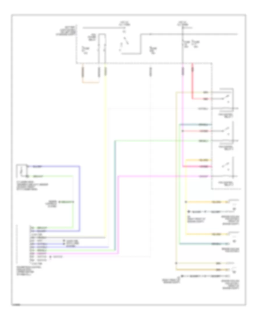
Cooling Fan Wiring Diagram, Except Hybrid for Mazda Tribute i Grand Touring 2010
 https://portal-diagnostov.com/license.html
Automotive Electricians Portal FZCO
Automotive Electricians Portal FZCO
https://portal-diagnostov.com/license.html
https://portal-diagnostov.com/license.html
Automotive Electricians Portal FZCO
Automotive Electricians Portal FZCO
List of elements for Cooling Fan Wiring Diagram, Except Hybrid for Mazda Tribute i Grand Touring 2010:
- (2.5l)
- (3.0l)
- 0140-175b
- 0140-175e
- 0140-275b
- 0140-275e
- 2.5l
- 3.0l
- Battery junction box (bjb) (on left side of engine compt)
- Computer data lines system
- Cooling fan relay
- Cylinder head temperature sensor (2.5l: on right front of cylinder head) (3.0l: front center of engine)
- Engine control system
- Engine cooling fan motor 1 (front of engine compt)
- Engine cooling fan motor 2 (front of engine compt)
- Engine cooling fan motor 3 (front of engine compt)
- Fuse 10a
- Fuse 40a
- G3 (right front of engine compt)
- High speed fan control relay
- Hot at all times
- Low speed fan control relay
- Pcm power relay
- Powertrain control module (pcm) (upper center of firewall)
- Red
Cooling Fan Wiring Diagram, Hybrid for Mazda Tribute i Grand Touring 2010
List of elements for Cooling Fan Wiring Diagram, Hybrid for Mazda Tribute i Grand Touring 2010:
- 0140-175b
- 0140-175e
- Battery junction box (on left side of engine compt)
- Computer data lines system
- Cylinder head temperature (cht) sensor (on right front of cylinder head)
- Engine controls system
- Engine cooling fan motor 1 (front of engine compt)
- Engine cooling fan motor 2 (front of engine compt)
- Engine cooling fan motor 3
- Fan control relay 1
- Fan control relay 2
- Fan control relay 3
- Fuse 10a
- Fuse 15a
- Fuse 40a
- G3 (right front of engine compt)
- Hot at all times
- Pcm power relay
- Powertrain control module (pcm) (upper center of firewall)
- Red

 Čeština
 Dansk
Dansk Deutsch
 Ελληνικά
 English
 English
 Español
 Suomi
Suomi Français
 Français
 עברית
עברית Magyar
 Italiano
 日本語
日本語 한국어
한국어 Nederlands
 Polski
 Português
 Português
 Română
 Русский
 Slovenčina
 Slovenščina
 Svenska
 Türkçe
 中文 (中国)