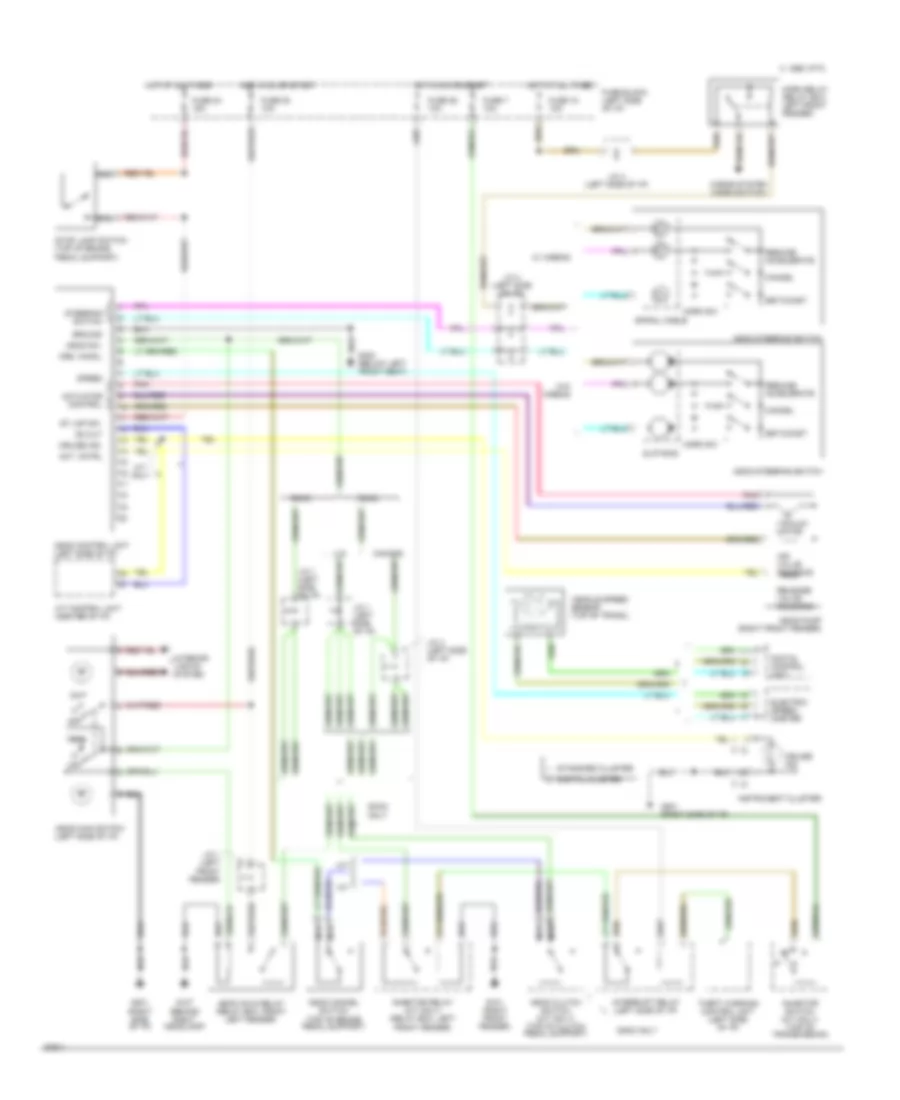
CRUISE CONTROL
Cruise Control Wiring Diagram for Nissan Maxima GXE 1994
List of elements for Cruise Control Wiring Diagram for Nissan Maxima GXE 1994:
- 1995 vftc c
- A/t
- A/t control unit (center of i/p)
- A/t only
- Act. cntrl
- Actuator control
- Air valve solenoid
- Ascd cancel switch (top of brake pedal support)
- Ascd clutch switch (m/t only) (top of clutch pedal support)
- Ascd control unit (left side of i/p)
- Ascd hold relay (relay box, front left fender)
- Ascd main switch (left side of i/p)
- Ascd pump (right front fender)
- Ascd steering switch
- Ascd sw.
- Canada
- Cancel
- Crs. cancl
- Cruise ind.
- Digital cluster
- Digital control unit
- Dohc
- Dohc only
- Electric speed- ometer
- Fuse 18 10a
- Fuse 20 10a
- Fuse 24 15a
- Fuse 26 10a
- Fuse 7 10a
- Fuse block (left side of i/p)
- G101 (right front fender)
- G107 (behind right headlamp)
- G201 (right side of i/p)
- G300 (below left front seat)
- Ground
- Horn relay (relay box, left front fender)
- Horn sw.
- Horns system (horn switch)
- Hot at all times
- Hot in on or start
- Inhibitor relay (a/t only) (relay box, left front fender)
- Inhibitor switch (a/t only) (top of transmission)
- Instrument cluster
- Interior lights system
- Interrupt relay (left side of i/p)
- J/c 1 (left front fender)
- J/c 1 (left side of i/p)
- J/c 4 (left side of i/p)
- M/t
- Nca
- Od cut
- Off
- Pnk
- Release valve solenoid
- Resume/ accelerate
- Set/coast
- Slip ring
- Sohc
- Speed
- Spiral cable
- St lmp sw.
- Standard cluster
- Steering switch
- Stop lamp switch (top of brake pedal support)
- Theft warning control unit (left side of i/p)
- U.s.
- Vacuum motor
- Vehicle speed sensor (top of trans.)
- W/ airbag
- W/o airbag
 Čeština
 Dansk
Dansk Deutsch
 Ελληνικά
 English
 English
 Español
 Suomi
Suomi Français
 Français
 עברית
עברית Magyar
 Italiano
 日本語
日本語 한국어
한국어 Nederlands
 Polski
 Português
 Português
 Română
 Русский
 Slovenčina
 Slovenščina
 Svenska
 Türkçe
 中文 (中国)
 Hrvatski