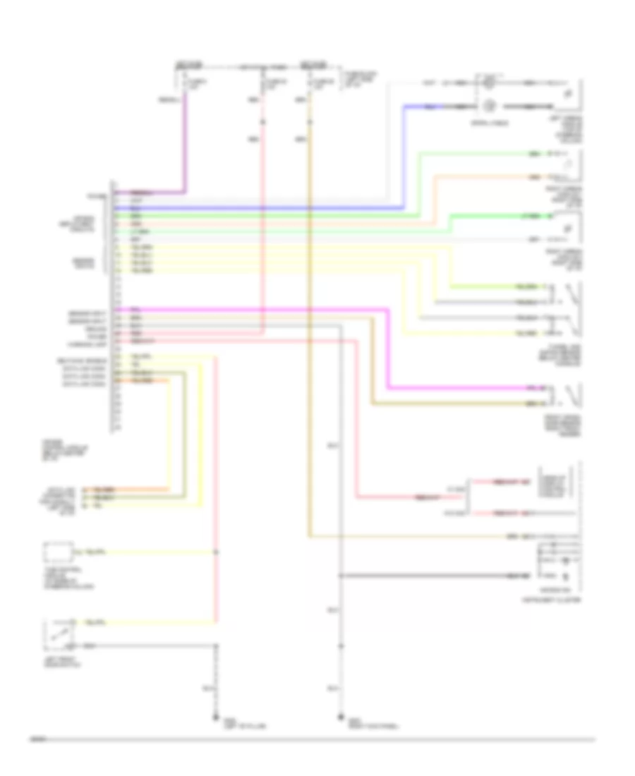
SUPPLEMENTAL RESTRAINTS
Supplemental Restraint Wiring Diagram for Nissan Altima GXE 1994
List of elements for Supplemental Restraint Wiring Diagram for Nissan Altima GXE 1994:
- Air bag control module (below center of i/p)
- Air bag deployment circuits
- Air bag ind.
- Data link conn.
- Data link connector for consult (left side of i/p)
- Front crash zone sensor (right front fender)
- Fuse 20 10a
- Fuse 25 10a
- Fuse 5 10a
- Fuse block (left side of i/p)
- G203 (right kick panel)
- G308 (left "b" pillar)
- Ground
- Head-up display control module
- Hot at all times
- Hot in on or start
- Instrument cluster
- Left airbag module (top of steering column)
- Left front door switch
- Nca
- Power
- Red
- Right airbag module 1 (right side of i/p)
- Right airbag module 2 (right side of i/p)
- Self diag. enable
- Sensor input
- Sensor inputs
- Spiral cable
- Time control module (at base of steering column)
- Tunnel and safing sensor (below center console)
- W/ hud
- W/o hud
- Warning lamp
 Čeština
 Dansk
Dansk Deutsch
 Ελληνικά
 English
 English
 Español
 Suomi
Suomi Français
 Français
 עברית
עברית Magyar
 Italiano
 日本語
日本語 한국어
한국어 Nederlands
 Polski
 Português
 Português
 Română
 Русский
 Slovenčina
 Slovenščina
 Svenska
 Türkçe
 中文 (中国)
 Hrvatski