СИСТЕМА ПЕРЕДАЧИ ДАННЫХ
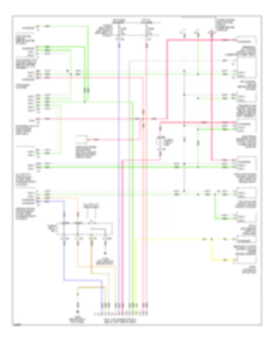
Электросхема линии передачи данных CAN для Mercedes-Benz ML500 2003
Электросхема линии передачи данных CAN для Mercedes-Benz ML500 2003 - Список элементов:
- A12
- Aac pushbutton control module (behind center of dash)
- All activity module (aam)
- All activity module (aam) (in left side of engine compt, in "e" box)
- B10
- B11
- B12
- C/b
- C/c
- C/e
- C2 pnk
- Can h
- Can l
- Data link connector (dlc) (below left side of dash)
- Diag
- Diagnosis
- Electronic selector lever control module (under center console)
- Emergency call system control module (under right front seat)
- Engine control module (me-sfi) (in left side of engine compt, in "e" box)
- Etc control module (behind center of dash)
- Extended activity module (eam) (right front footwell)
- Fuse & relay box
- Fuse & relay box (left side of eng compt, in "e" box)
- Fuse 10a
- Fuse 15a
- Headlamp range adjustment control module (behind driver's side of dash)
- Hot at all times
- Hot in run or start
- Instrument cluster
- Lower control field control module (under center console)
- Mr/d
- P/b
- P/d
- Pnk
- Pts control module (behind center of dash)
- Radio (or radio & navigation)
- Rain & light sensor (front of headliner)
- Red
- Restraint system control module (under center console)
- Traction systems control module (left front of engine compt)
- Transfer case control module (below center console, behind shift assembly)
- Trip computer control module (in front of roof)
- W16/5 (left rear of engine compt)
- W29/2 (behind right kick panel)
 Čeština
 Dansk
Dansk Deutsch
 Ελληνικά
 English
 English
 Español
 Suomi
Suomi Français
 Français
 עברית
עברית Magyar
 Italiano
 日本語
日本語 한국어
한국어 Nederlands
 Polski
 Português
 Português
 Română
 Русский
 Slovenčina
 Slovenščina
 Svenska
 Türkçe
 中文 (中国)
 Hrvatski