SHIFT INTERLOCK
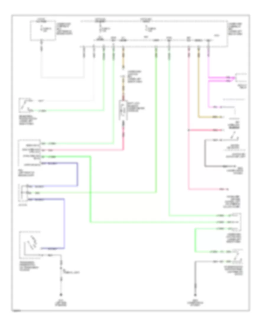
Shift Interlock Wiring Diagram for Acura RDX 2011
List of elements for Shift Interlock Wiring Diagram for Acura RDX 2011:
- (atpp) drive in
- (bksw) sw in
- (p-pin) park pin a2
- (sls) interlock a27
- A/t gear position indicator panel light/park pin switch
- A22
- A23
- A40
- Acc
- Acc cut relay
- Atpp
- B13
- Brake pedal position switch (under left side of dash)
- Ctrl out
- E11
- E16
- F25
- F27
- F30
- F31
- Fuse 10 7.5a
- Fuse 12 15a
- Fuse 35 7.5a
- G101 (left side of engine)
- G16
- G502 (under middle of dash)
- G503 (under middle of dash)
- Hot at all times
- Hot in acc or on
- Hot in on or start
- Ig 1 meter
- Ignition key switch
- Ignition key switch/ key light
- Immobilizer- keyless control unit (on steering column cover)
- J/c c103
- J10
- Key interlock solenoid
- Key sw
- Keysol
- Micu
- P-pin sw
- Pcm (left front of engine compt)
- Pnk
- Q14
- Red
- S2 (thermal joint)
- Shift lock solenoid (under center console)
- Stop sw
- Sw in
- Transmission range switch (on transmission housing)
- Under-dash fuse/relay box (under left end of dash)
- Under-dash junction box (under left side of dash)
- Under-hood fuse/relay box (left rear of engine compt)
 Čeština
 Dansk
Dansk Deutsch
 Ελληνικά
 English
 English
 Español
 Suomi
Suomi Français
 Français
 עברית
עברית Magyar
 Italiano
 日本語
日本語 한국어
한국어 Nederlands
 Polski
 Português
 Português
 Română
 Русский
 Slovenčina
 Slovenščina
 Svenska
 Türkçe
 中文 (中国)
 Hrvatski