TRANSMISSION
4.3L
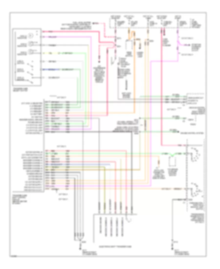
4.3L (VIN W), Transmission Wiring Diagram, 4L60-E for Chevrolet Blazer 1997
 https://portal-diagnostov.com/license.html
Automotive Electricians Portal FZCO
Automotive Electricians Portal FZCO
https://portal-diagnostov.com/license.html
https://portal-diagnostov.com/license.html
Automotive Electricians Portal FZCO
Automotive Electricians Portal FZCO
List of elements for 4.3L (VIN W), Transmission Wiring Diagram, 4L60-E for Chevrolet Blazer 1997:
- (behind left side of dash)
- (eng harn, 19 cm from inj harn breakout) s115
- (twisted wire pair)
- 1-2 shift sol
- 1-2 shift sol ctrl
- 2-3 shift sol
- 2-3 shift sol ctrl
- 3-2 shift sol
- 3-2 sol ctrl
- 5v reference
- All times
- And start
- Anti-lock brakes system
- Automatic transmission (4l60-e)
- Battery feed
- Brake fuse 12 10a
- Brake pressure modulator valve, cruise control module & cruise control switch
- Brake signal
- Cruise control system
- Data link connector (partial) (below left side of dash)
- Ecm batt
- Ecm ign fuse 10 20a
- Ect signal
- Electronic ignition control module, crankshaft position sensor, ignition coil & fuel injectors)
- Engine controls system
- Engine coolant temperature sensor (thermostat housing)
- Fuel pump relay
- Fuel pump switch/ engine oil pressure gauge sensor
- Fuse 9 20a
- G114 (rear of left cylinder head)
- G117 (rear of right cylinder head)
- Gauges fuse 4 10a
- Hot at
- Hot in
- Hot in run
- Hot in run, bulb
- I/p fuse block
- Ignition feed
- Instrument cluster
- Malfunction indicator lamp
- Mil ctrl
- Park pawl actuator (w/ a/t) & instrument cluster
- Park pawl actuator (w/ floor shift) or instrument cluster (w/ column shift)
- Pickup
- Pnk
- Press ctrl so hi
- Press ctrl sol lo
- Pressure control solenoid
- Range signal-a
- Range signal-b
- Range signal-c
- Red
- Rev
- Run
- Run feed
- S100 (eng harn 30 cm from vcm breakout)
- S106
- S108
- S140
- S220
- S227 (dash harn, approx 8 cm from data link conn breakout)
- S238 (dash harn, approx 11 cm from tcc brake & cruise control rel sw breakout)
- S239
- S266
- Sensor ground
- Serial data
- Shield
- System gnd
- Tan
- Tcc brake & cruise control release switch (on brake pedal bracket)
- Tcc pwm sol
- Tcc pwm sol ctrl
- Tcc sol
- Tcc sol ctrl
- Test or start
- Tft signal
- Throttle position sensor
- Tp signal
- Trans fuse 24 10a
- Transmission fluid temperature sensor
- Transmission range pressure switch assembly
- Utility
- Vehicle control module (right side of engine compt)
- Vehicle speed sensor (on transmission-2wd) (on transfer case-4wd)
- Vss hi
- Vss lo
Electronic Transfer Case Wiring Diagram for Chevrolet Blazer 1997
List of elements for Electronic Transfer Case Wiring Diagram for Chevrolet Blazer 1997:
- (a/t only)
- (a/t) 4wd lo selected
- (a/t) pnp switch in (p)
- (dash harn, 20 cm from breakout of 23-pin conn behind right side of dash) s259
- (m/t only)
- (w/ m/t only)
- 12v battery
- 12v ignition
- 2 hi request
- 2 hi status lamp
- 2wd hi indicator
- 2wd hi switch
- 4 hi request
- 4 hi status lamp
- 4 lo request
- 4 lo status lamp
- 4wd fuse 19 20 a
- 4wd hi indicator
- 4wd hi switch
- 4wd lo in
- 4wd lo indicator
- 4wd lo switch
- A/c compressor relay & inflatable restraint diagnostic energy reserve module
- Anti-lock brakes system
- Axle sw in
- C10
- C11
- C12
- C14
- C16
- Chassis ground
- Crank fuse 20 20a
- Cruise control system
- D10
- D12
- D13
- D14
- D15
- D16
- Data link connector
- Data link connector (partial) (lower left side of dash)
- Electronic shift transfer case
- Encoder channel a
- Encoder channel b
- Encoder channel c
- Encoder channel d
- Encoder channel-a
- Encoder channel-b
- Encoder channel-c
- Encoder channel-d
- Encoder ground
- Encoder signal ground
- Front axle switch (on front axle)
- Fuel level buffer, daytime running lamps relay, instrument cluster & rear window defogger switch
- G117 (rear of right cylinder head)
- Gauges fuse 4 10a
- Gnd
- Head- lamp switch
- Hot at all times
- Hot in run or start
- Hot in start
- I/p fuse block (left end of dash)
- Motor control a
- Motor control b
- Motor ground
- Park/neutral position & backup lamp switch
- Pk lps fuse 3 20a
- Pnk
- Pnp switch in (a/t)
- Pnp switch in (m/t)
- Power ground
- Radio
- Red
- S112
- S212 (i/p harn, approx 7 cm from radio breakout)
- S213
- S241
- S242
- S246
- S253
- Starting/ charging system (w/ m/t)
- Tcc brake & cruise control switch
- Transfer case select switch
- Transfer case shift control module (behind center of dash)
- Transmission range switch (left side of transmission) (a/t only)
- Turn b/u fuse 16 15a
- Turn signal lamp flasher
- Under- hood lamp
- Vehicle control module (right side of engine compt)
- Vehicle spd out
- Vehicle speed in
- Vss in

 Čeština
 Dansk
Dansk Deutsch
 Ελληνικά
 English
 English
 Español
 Suomi
Suomi Français
 Français
 עברית
עברית Magyar
 Italiano
 日本語
日本語 한국어
한국어 Nederlands
 Polski
 Português
 Português
 Română
 Русский
 Slovenčina
 Slovenščina
 Svenska
 Türkçe
 中文 (中国)