
 Čeština
 Dansk
Dansk Deutsch
 Ελληνικά
 English
 English
 Español
 Suomi
Suomi Français
 Français
 עברית
עברית Magyar
 Italiano
 日本語
日本語 한국어
한국어 Nederlands
 Polski
 Português
 Português
 Română
 Русский
 Slovenčina
 Slovenščina
 Svenska
 Türkçe
 中文 (中国)

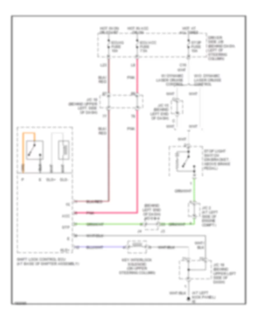
SHIFT INTERLOCK
Shift Interlock Wiring Diagram for Toyota Sienna CE 2005
List of elements for Shift Interlock Wiring Diagram for Toyota Sienna CE 2005:

ANTI-LOCK BRAKESCOOLING FANANTI-THEFTCRUISE CONTROLAIR CONDITIONINGCOMPUTER DATA LINESBODY CONTROL MODULESDEFOGGERSENGINE PERFORMANCEHEADLIGHTSEXTERIOR LIGHTSHORNINTERIOR LIGHTSINSTRUMENT CLUSTERGROUND DISTRIBUTIONNAVIGATIONPOWER WINDOWSPOWER DISTRIBUTIONPOWER TOP/SUNROOFSHIFT INTERLOCKPOWER MIRRORSPOWER SEATSRADIOTRANSMISSIONSTARTING/CHARGINGSUPPLEMENTAL RESTRAINTSTRUNK, TAILGATE, FUEL DOORWARNING SYSTEMSWIPER/WASHER