
 Čeština
 Dansk
Dansk Deutsch
 Ελληνικά
 English
 English
 Español
 Suomi
Suomi Français
 Français
 עברית
עברית Magyar
 Italiano
 日本語
日本語 한국어
한국어 Nederlands
 Polski
 Português
 Português
 Română
 Русский
 Slovenčina
 Slovenščina
 Svenska
 Türkçe
 中文 (中国)

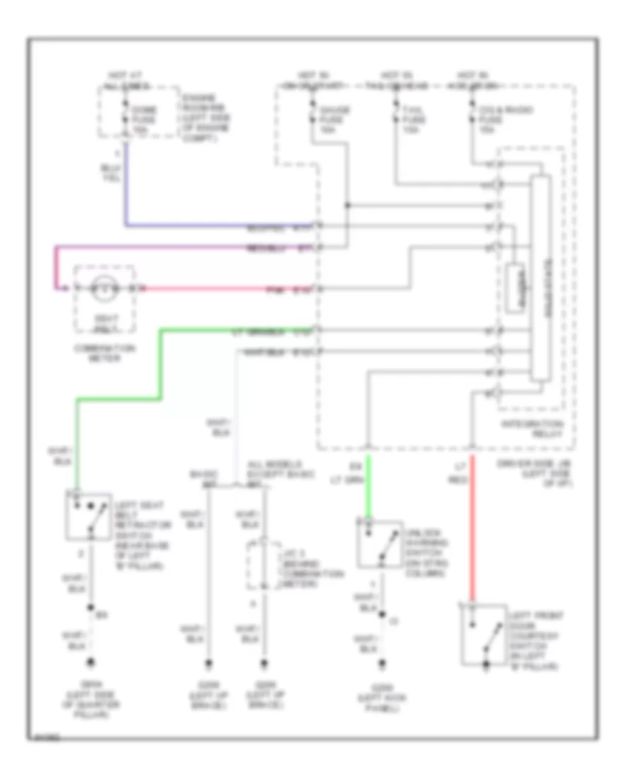
WARNING SYSTEMS
Warning System Wiring Diagrams for Toyota Tercel CE 1997
List of elements for Warning System Wiring Diagrams for Toyota Tercel CE 1997:

COOLING FANCOMPUTER DATA LINESANTI-LOCK BRAKESANTI-THEFTEXTERIOR LIGHTSAIR CONDITIONINGENGINE PERFORMANCEDEFOGGERSGROUND DISTRIBUTIONHEADLIGHTSHORNINSTRUMENT CLUSTERPOWER WINDOWSSTARTING/CHARGINGPOWER DOOR LOCKSRADIOINTERIOR LIGHTSSUPPLEMENTAL RESTRAINTSPOWER DISTRIBUTIONSHIFT INTERLOCKSTRANSMISSIONWARNING SYSTEMSWIPER/WASHER