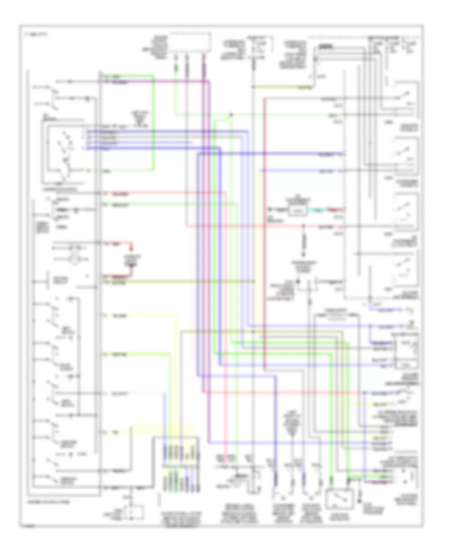
AIR CONDITIONING
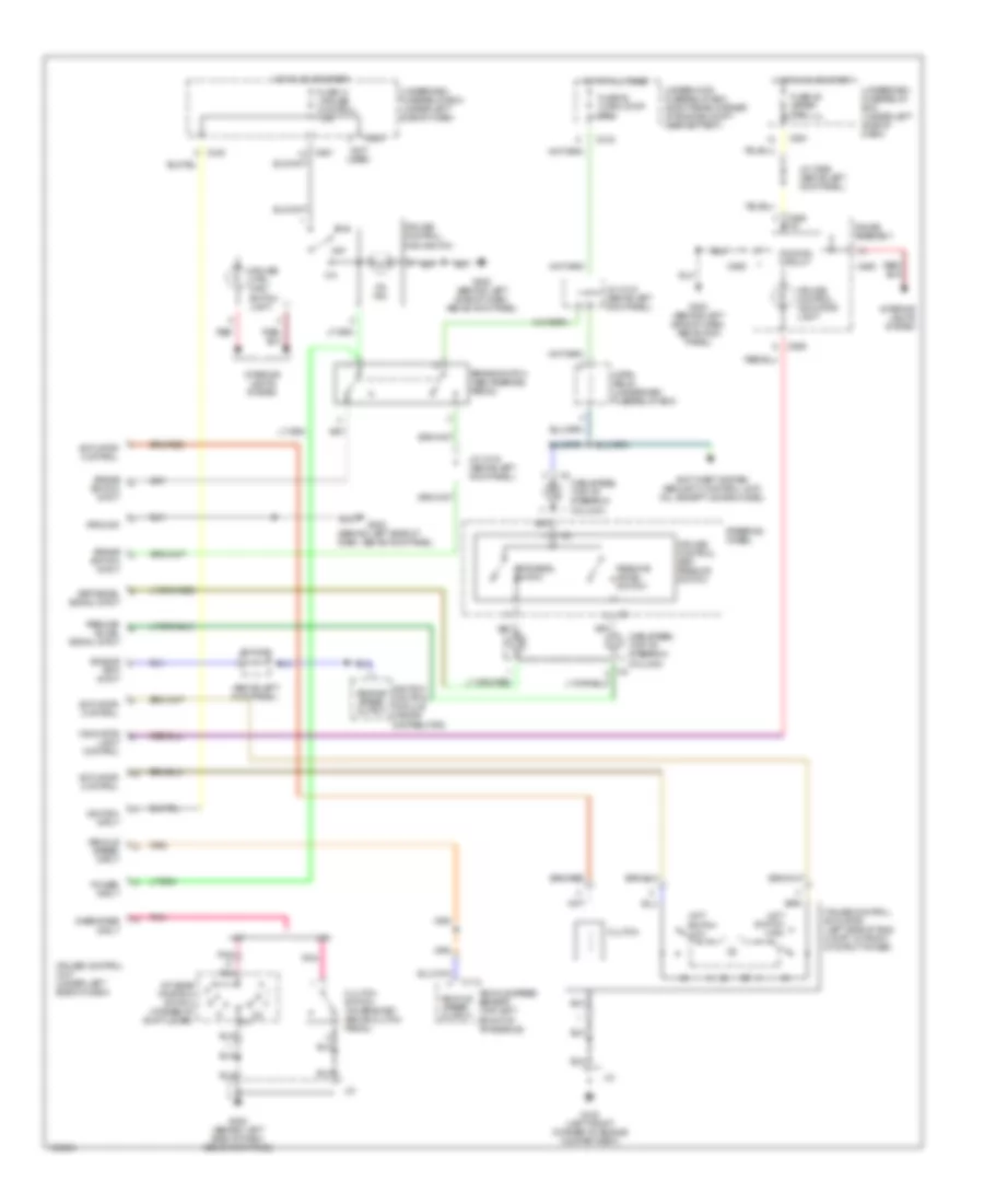
Heater Wiring Diagram for Acura Integra GS-R 1999
 https://portal-diagnostov.com/license.html
Automotive Electricians Portal FZCO
Automotive Electricians Portal FZCO
https://portal-diagnostov.com/license.html
https://portal-diagnostov.com/license.html
Automotive Electricians Portal FZCO
Automotive Electricians Portal FZCO
List of elements for Heater Wiring Diagram for Acura Integra GS-R 1999:
- (behind glove box on rear left side of blower housing)
- (behind glove box, on top of blower motor housing)
- (left kick
- (left kick panel) g200
- All times
- Bi-lev switch
- Blower motor (behind glove box, on bottom of blower motor housing)
- Blower motor relay
- Blower resistor
- C 1995 vftc
- C216
- C217
- C439
- C907
- Compartment)
- Defrost switch
- Dimming circuit
- Fresh
- Fresh/ recirc switch
- Fuse 40a
- Fuse 7.5a
- G101 (right front corner of engine
- G200
- Heat switch
- Heat/def switch
- Heater control panel
- Heater fan switch
- Hot at
- Hot in on
- Interior lights system
- Mode control motor (behind left side of dash, on left side of heater assembly)
- Off
- Panel)
- Recirc
- Recirculation control motor
- Red
- Underdash fuse/relay box (under left side of dash)
- Underhood fuse/relay box (right rear corner of engine compt, near battery)
- Vent switch
Manual A/C Wiring Diagram for Acura Integra GS-R 1999
List of elements for Manual A/C Wiring Diagram for Acura Integra GS-R 1999:
- (behind glove box)
- (behind glove box, on rear left side of blower housing)
- (left front of engine compart- ment) g100
- (left kick
- (left kick panel) g200
- (on bracket)
- A/c compressor clutch
- A/c compressor clutch relay
- A/c diode (above right kick panel)
- A/c pressure switch (in refrig pipe, between receiver-driver & condenser)
- A/c switch
- A/c thermostat (in evap housing, on evaporator core)
- Bi-lev switch
- Blower motor
- Blower motor relay
- Blower resistor
- C 1995 vftc
- C215
- C216
- C217
- C439
- C904
- C905
- C906
- C907
- Compartment)
- Condenser fan motor (behind left side of radiator)
- Condenser fan relay
- Defrost switch
- Dimming circuit
- Diode
- Engine control module (behind right side kick panel)
- Fresh
- Fresh/ recirc switch
- Fuse 20a
- Fuse 40a
- Fuse 7.5a
- G101 (right front corner of engine
- G120 (right side of engine)
- G200
- Heat switch
- Heat/def switch
- Heater control panel
- Heater fan switch
- High
- Hot at all times
- Hot in on underdash fuse/relay box (under left side of dash)
- Interior lights system
- Low
- Mode control motor (behind left side of dash, on left side of heater assembly)
- Nca
- Off
- Panel)
- Radiator fan motor (behind right side of radiator)
- Radiator fan relay
- Radiator fan switch
- Recirc
- Recirculation control motor
- Red
- Thermistor
- Transmission control system
- Underhood fuse/relay box (right rear corner of engine compt, near battery)
- Vent switch
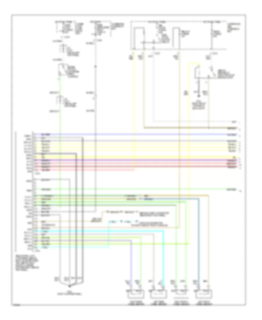
ANTI-LOCK BRAKES
Anti-lock Brakes Wiring Diagram (1 of 2) for Acura Integra GS-R 1999
List of elements for Anti-lock Brakes Wiring Diagram (1 of 2) for Acura Integra GS-R 1999:
- (on right side of front console)
- 4
- Abs b1 fuse 62 20a
- Abs control unit (hatchback: behind right quarter panel trim, sedan: right side of luggage compartment, behind trim panel)
- Abs fail- safe relay (right front of engine compt)
- Abs motor fuse 61 40a
- Abs pump motor relay
- Abs unit fuse 65 10a
- Brake switch (on brake pedal support)
- C212
- C213
- C216
- C438
- C703
- C704
- Data link connector
- Dlc
- Fl-in
- Fl-out
- Flw (+)
- Flw (-)
- Fr-in
- Fr-out
- Frw (+)
- Frw (-)
- Fsr
- G101 (right front corner of eng compt)
- G401 (right quarter panel)
- Gnd1
- Gnd2
- Gnd3
- Gnd4
- Horn, stop fuse 52 20a
- Hot at all times
- Hot in on
- Ig2
- J/c c418 (above left kick panel)
- Left front wheel sensor
- Left rear wheel sensor
- Mck
- Park
- Pmr
- Rear defroster relay fuse 16 7.5a
- Right front wheel sensor
- Right rear wheel sensor
- Rl-in
- Rl-out
- Rlw (+)
- Rlw (-)
- Rr-in
- Rr-out
- Rrw (+)
- Rrw (-)
- Scs
- Service check connector (above right kick panel)
- Stop
- Under- hood fuse/ relay box
- Underdash fuse/relay box
- Underhood abs fuse/relay box
- Warn 1
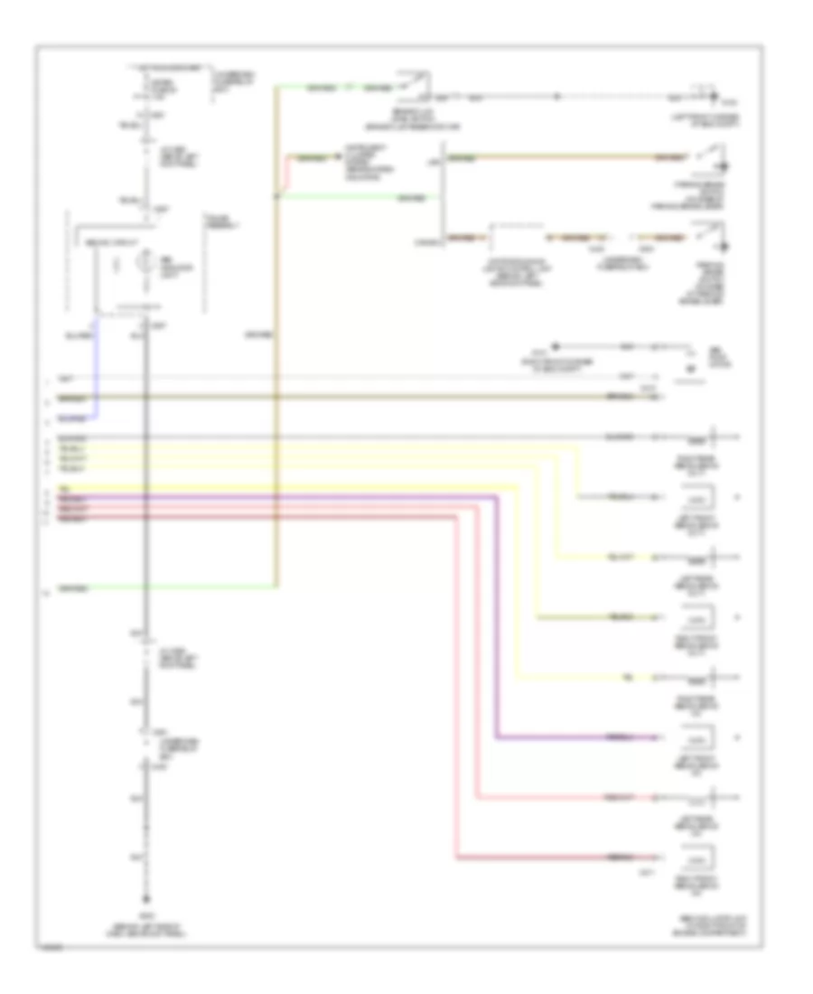
Anti-lock Brakes Wiring Diagram (2 of 2) for Acura Integra GS-R 1999
List of elements for Anti-lock Brakes Wiring Diagram (2 of 2) for Acura Integra GS-R 1999:
- (behind left side of dash, above kick panel)
- (left front corner of eng compt)
- (right front corner of eng compt)
- Abs ind. circuit
- Abs indicator light
- Abs modulator unit (in right front of engine compartment)
- Abs pump motor
- Brake fluid level switch (brake fluid reservoir cap)
- C210
- C211
- C439
- C440
- C504
- C551
- C557
- Canada
- Daytime running lights control unit (behind left side kick panel)
- G100
- G101
- G202
- Gauge assembly
- Hot in on or start
- Instrument cluster system (brake system indicator)
- J/c c556 (above left kick panel)
- Left front abs solenoid (in)
- Left front abs solenoid (out)
- Left rear abs solenoid (in)
- Left rear abs solenoid (out)
- Meter fuse 25 7.5a
- Parking brake switch (on base of parking brake lever)
- Right front abs solenoid (in)
- Right front abs solenoid (out)
- Right rear abs solenoid (in)
- Right rear abs solenoid (out)
- Underdash fuse/relay box
- Usa
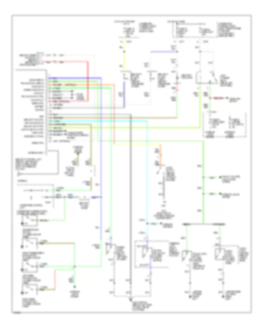
ANTI-THEFT
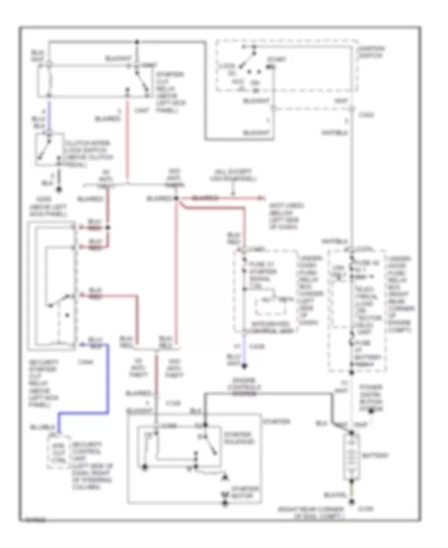
Anti-theft Wiring Diagram for Acura Integra GS-R 1999
List of elements for Anti-theft Wiring Diagram for Acura Integra GS-R 1999:
- (center of rear shelf) g311
- (center rear of cargo area) g407
- (optional)
- Antenna
- Antenna input
- Battery
- C216
- C217
- C440
- C441
- C449
- Ceiling light ctrl
- Disarm/ valet switch (below left side of dash)
- Disarm/valet sw in
- Door locks system
- Door open in
- Dr unlock rly ctrl
- Driver's door switch (closed w/door open)
- Exterior lamps system
- Front passenger's door switch (closed w/door open)
- Fuse 19 back up lights 7.5a
- Fuse 19 back up, radio 7.5a
- Fuse 30 instrument lights 7.5a
- Fuse 32 license tail lights 10a
- Fuse 48 headlight 40a
- G101 (right front corner of engine compartment)
- G202 (partial) (behind left side of dash, above kick panel)
- Gnd
- Hatch latch (center rear of cargo area)
- Hatch latch switch (closed w/hatch open)
- Hatchback
- Headlamp switch
- Hood sw in
- Hood switch (behind center of front bumper)
- Horn ctrl
- Horns system starting/charging system
- Hot at all times
- Hot in on or start
- Ignition
- Ignition key sw in
- Ignition key switch (closed w/key in ignition)
- Integrated control unit
- Interior lamps system
- Interior lights system
- J/c c418 (above left kick panel)
- Left rear door switch (closed w/door open)
- Light flash rly ctrl
- Light flasher relay (above left kick panel)
- Lock out
- Red
- Right rear door switch (closed w/door open)
- Security control unit (behind left side of dash lower cover, right of steering column)
- Security in-line diode
- Security in-line fuse 1 (behind dashboard cover)
- Security in-line fuse 2 (behind dashboard cover)
- Security ind ctrl
- Security indicator
- Security siren (optional) (behind center of front bumper)
- Sedan
- Siren ctrl
- Starter cut ctrl
- Steering lock (right side of steering column)
- Trunk latch switch (closed w/trunk open) (center of trunk lid)
- Trunk, tailgate, fuel doors system
- Trunk/hatch open in
- Underdash fuse/relay box (under left side of dash)
- Underhood fuse/relay box (right rear corner of engine compartment, near battery)
- Unlock out
- Warning systems
BODY CONTROL MODULES
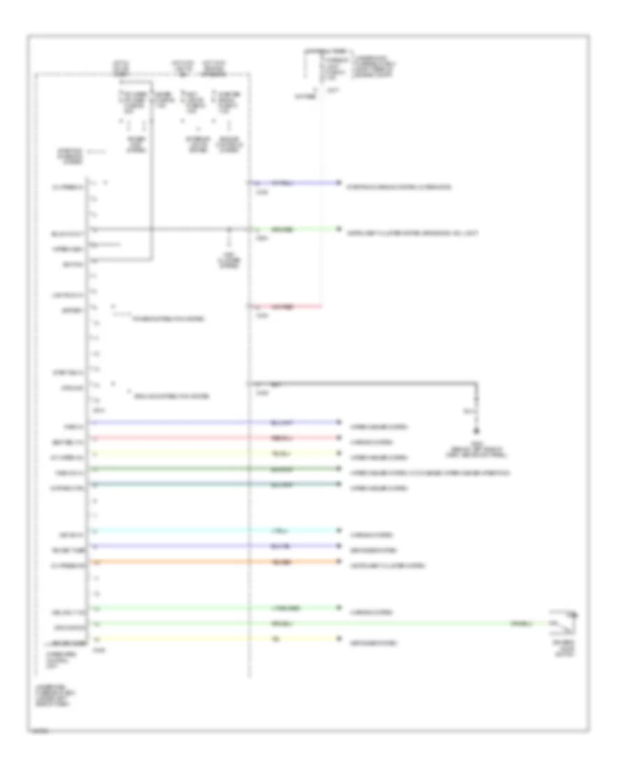
Integrated Control Unit Wiring Diagram for Acura Integra GS-R 1999
List of elements for Integrated Control Unit Wiring Diagram for Acura Integra GS-R 1999:
- Battery
- Bulb ck out
- C217
- C438
- C439
- C440
- C449
- C504
- C914
- Ceiling lt on
- Defogger system
- Dr door sw
- Driver's door switch
- Engine controls system
- Exterior lights system
- Fr wiper fr wash fuse 26 20a
- G202 (behind left side of dash, above kick panel)
- Ground
- Ground distribution system
- Hot at all times
- Hot in on or start
- Hot with engine cranking
- Hot with lights on
- Ignition
- Inst lights fuse 30 7.5a
- Inst. cluster system
- Instrument cluster system
- Instrument cluster system (brake sys. ind. light)
- Int wiper on
- Int/park ctrl
- Integrated control unit
- Interior light fuse 43 7.5a
- Key sw in
- Lights on in
- Meter fuse 25 7.5a
- Oil press in
- Oil press ind
- Park in
- Power dist. system
- Power distribution system
- Rr def timer
- Seat belt in
- Start sig in
- Starter signal fuse 31 7.5a
- Starting/ charging system
- Starting/charging system (alternator)
- Underdash fuse/relay box (under left side of dash)
- Underhood fuse/relay box (right rear of engine compt)
- Warning system
- Wash on in
- Wiper/wash
- Wiper/washer system
- Wiper/washer system (w/ combined wiper/washer operation)
COMPUTER DATA LINES
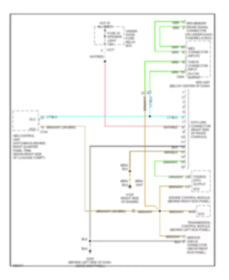
Computer Data Lines Wiring Diagram for Acura Integra GS-R 1999
List of elements for Computer Data Lines Wiring Diagram for Acura Integra GS-R 1999:
- (on under-dash fuse/relay box)
- Abs control unit (hatchback-behind right quarter panel trim, sedan-right side of luggage compt)
- B14 scs
- C217
- C704
- C804
- Check connector input
- Connector (above right kick panel)
- Data link connector (right side of front console)
- Data output
- Dlc
- Dlc in/ output
- Engine control module (behind right kick panel)
- Fuse 43 interior light 7.5a
- G120 (right side of engine)
- G202 (behind left side of dash, above kick panel)
- Hot at all times
- Mes connector inputs
- Scs
- Srs memory erase signal connector
- Srs unit (below center of dash)
- Transmission control module (behind left kick panel)
- Txd/rxd c8
- Under- hood fuse/ relay box
COOLING FAN
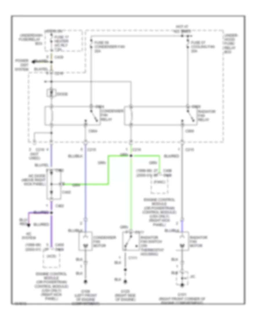
Cooling Fan Wiring Diagram, with A/C for Acura Integra GS-R 1999
List of elements for Cooling Fan Wiring Diagram, with A/C for Acura Integra GS-R 1999:
- (1998-99)
- (2000-01)
- (acs)
- (fanc)
- A/c diode (above right kick panel)
- A/c system
- Box
- C111
- C215
- C216
- C216 (not used)
- C402
- C408
- C409
- C439
- C904
- C906
- Condenser fan motor
- Condenser fan relay
- Diode
- Engine control module (or powertrain control module) (usa only) (right kick panel)
- Fuse 17 heater a/c rly 7.5a
- Fuse 56 condenser fan 20a
- Fuse 57 cooling fan 20a
- G101 (right front corner of engine compartment)
- G108 (left front of engine compartment)
- G120 (right side of engine)
- Hot at all times
- Hot in on
- J/c
- Power dist system
- Radiator fan motor
- Radiator fan relay
- Radiator fan switch (on thermostat housing)
- Under- hood fuse/ relay box
- Underdash fuse/relay
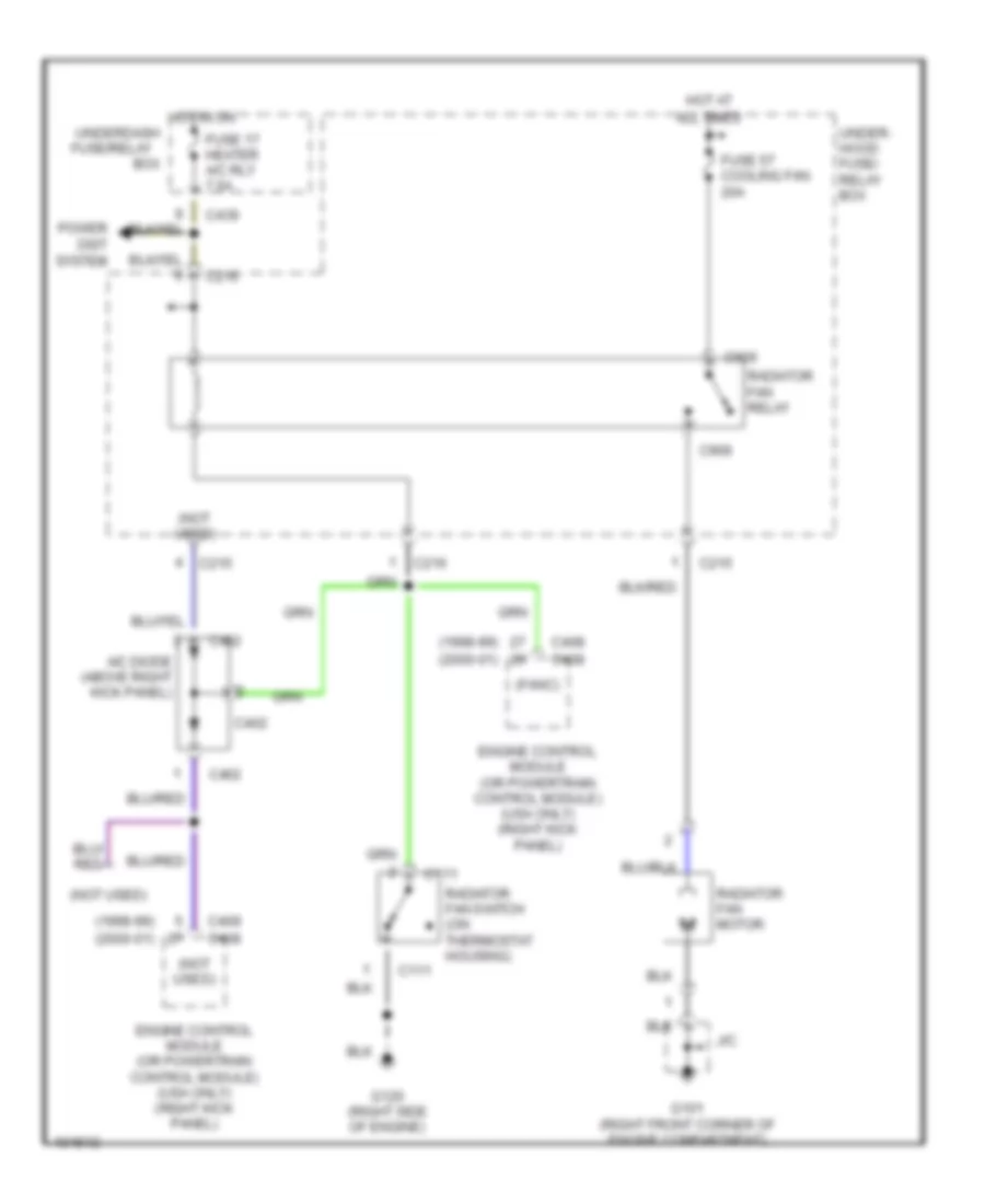
Cooling Fan Wiring Diagram, without A/C for Acura Integra GS-R 1999
List of elements for Cooling Fan Wiring Diagram, without A/C for Acura Integra GS-R 1999:
- (1998-99)
- (2000-01)
- (fanc)
- (not used)
- A/c diode (above right kick panel)
- Box
- C111
- C215
- C216
- C402
- C408
- C409
- C439
- C906
- Engine control module (or powertrain control module) (usa only) (right kick panel)
- Fuse 17 heater a/c rly 7.5a
- Fuse 57 cooling fan 20a
- G101 (right front corner of engine compartment)
- G120 (right side of engine)
- Hot at all times
- Hot in on
- J/c
- Power dist system
- Radiator fan motor
- Radiator fan relay
- Radiator fan switch (on thermostat housing)
- Under- hood fuse/ relay box
- Underdash fuse/relay
CRUISE CONTROL
Cruise Control Wiring Diagram for Acura Integra GS-R 1999
List of elements for Cruise Control Wiring Diagram for Acura Integra GS-R 1999:
- (above left kick panel)
- (behind left side of dash, above kick panel)
- (not used)
- A/t
- A/t gear position switch (at base of shift lever)
- Actuator control
- Anti-theft system (security control unit) (all except usa rs model)
- Brake switch (above brake pedal)
- Brake switch input
- C112
- C216
- C440
- C504
- C551
- C559
- C560
- Cable reel (top of steering column)
- Clutch
- Clutch switch (on bracket, above clutch pedal)
- Cruise control actuator (left side of eng compt, in front of strut tower)
- Cruise control indicator light
- Cruise control main switch
- Cruise control set/ resume switch
- Cruise control unit (under left side of dash)
- Cruise ctrl. main switch light
- Dimming circuit
- Disengage input
- Engine rpm input
- Engine speed output
- Fuse 14 (cruise control) 7.5a
- Fuse 25 meter 7.5a
- Fuse 52 horn, stop 20a
- G100 (left front corner of engine compartment)
- G202
- G202 (behind left side of dash, above kick panel)
- Gauge assembly
- Ground
- Horn relay (underdash fuse/relay box)
- Hot at all times
- Hot in on or start
- Ignition control module (inside distributor)
- Ignition input
- Indicator light control
- Interior lights system
- J/c
- J/c c418
- J/c c418 (above left kick panel)
- J/c c556 (above left kick panel)
- Limit switch high
- Limit switch low
- M/t
- Off
- On ind.
- Pnk
- Power input
- Red
- Resume/ accel signal input
- Resume/ accel switch
- Set/decel signal input
- Set/decel switch
- Steering wheel
- Underdash fuse/relay box (under left side of dash)
- Underhood fuse/relay box (right rear corner of engine compt near battery)
- Vehicle speed input
- Vehicle speed output
- Vehicle speed sensor (top left front of transaxle)
DEFOGGERS
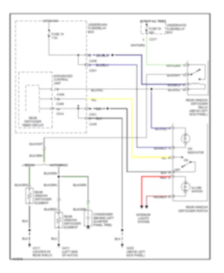
Defoggers Wiring Diagram for Acura Integra GS-R 1999
List of elements for Defoggers Wiring Diagram for Acura Integra GS-R 1999:
- C217
- C438
- C439
- C449
- C551
- C914
- Condenser (behind left quarter panel trim)
- Fuse 16 7.5a
- Fuse 50 40a
- G202 (above left kick panel)
- G311 (center of rear shelf)
- G411 (left side of hatch)
- Hatchback
- Hot at all times
- Hot in on
- Illumi- nation
- Integrated control unit
- Interior lights system
- Off
- On indicator
- Rear defogger timer circuit
- Rear window defogger element
- Rear window defogger relay (above left kick panel)
- Rear window defogger switch
- Red
- Sedan
- Underdash fuse/relay box
- Underhood fuse/relay box
ENGINE PERFORMANCE
1.8L
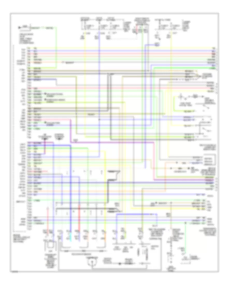
1.8L, Engine Performance Wiring Diagram (1 of 2) for Acura Integra GS-R 1999
List of elements for 1.8L, Engine Performance Wiring Diagram (1 of 2) for Acura Integra GS-R 1999:
- (right side of front console) data link connector
- (top rear of engine) g115
- 2wbs
- A10
- A11
- A12
- A13
- A14
- A15
- A16
- A17
- A18
- A19
- A20
- A21
- A22
- A23
- A24
- A25
- A26
- A27
- A28
- A29
- A30
- A31
- A32
- Abs control unit
- Acc
- Acs
- Afsa
- Afsb
- Air conditioning system
- Alt c
- Alt f
- At chk
- Atchk
- Atp pin
- Atp pn
- B14
- B19
- B20
- Baro out
- Box
- Braid
- C10
- C11
- C12
- C13
- C14
- C15
- C16
- C17
- C18
- C19
- C20
- C21
- C217
- C22
- C23
- C24
- C25
- C26
- C27
- C28
- C29
- C30
- C31
- C439
- Ckf
- Ckf m
- Ckf p
- Ckp
- Ckp m
- Ckp p
- Cooling fans system
- Crankshaft speed fluctuation sensor (behind timing belt cover)
- Cyp
- Cyp m
- Cyp p
- Distributor
- Engine control module (behind right kick panel)
- Fan c
- Fas
- Flk1
- Fuel pump (in fuel tank)
- Fuse 13 7.5a
- Fuse 31 7.5a
- Fuse 43 7.5a
- Fuse 44 15a
- Fuse 47 7.5a
- G200 (left kick panel)
- G309 (driver's door sill)
- Gauge assembly
- Ground
- Gs-r
- Hot at all times
- Hot in on or start
- Hot in start
- Iab cs
- Iacv
- Icm
- Ign
- Ign input signal
- Ignition
- Ignition coil
- Ignition control module
- Igp1
- Igp2
- Inj1
- Inj2
- Inj3
- Inj4
- Lg1
- Lg2
- Mil
- Orn
- P/n output
- Pcs
- Pg1
- Pg2
- Pgm-fi main relay (under left side of dash)
- Po2shtc
- Primary
- Primary output control
- Psp sw
- Red
- Rpm output
- Scs
- Secondary
- Service check connector (above right kick panel)
- So2shtc
- Srs unit
- Starting/ charging system
- Starting/charging system
- Sts
- Tdc
- Tdc m
- Tdc p
- Tdc/ckp/cyp sensor
- Test tachometer connector (left rear of eng compt)
- Transmission control module (behind left kick panel)
- Txd/rxd
- Under- dash fuse/ relay box
- Under- hood fuse/ relay
- Vbu
- Vehicle speed sensor (top left front of transaxle)
- Vref
- Vss
- Vss out
- Vsv
- Vt sol
- Vtec solenoid valve (gs-r, type-r) (on rear of cylinder head)
- Vtp sw
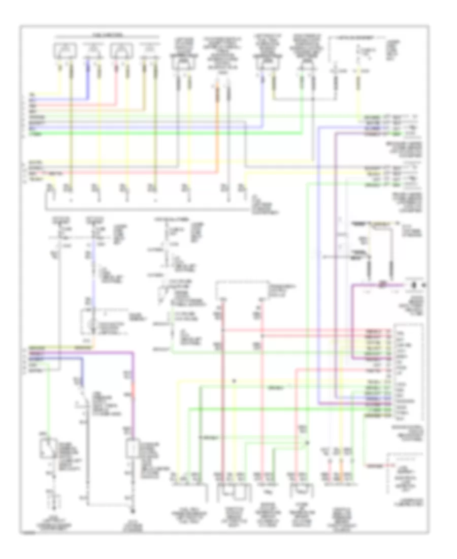
1.8L, Engine Performance Wiring Diagram (2 of 2) for Acura Integra GS-R 1999
List of elements for 1.8L, Engine Performance Wiring Diagram (2 of 2) for Acura Integra GS-R 1999:
- (left front of fuel tank) evaporative emission bypass solenoid valve
- (left side of intake manifold) idle air control valve
- (on intake manifold- except type-r, center of firewall- type-r) evaporative emission purge control solenoid valve
- (right rear of engine compt) evaporative emission control canister vent shut valve
- (w/ cruise)
- (w/o cruise)
- 15a
- 7.5a
- Bksw
- Braid
- Braided
- Brake switch (top of brake pedal support)
- C216
- C438
- C440
- C551
- D12
- Ect
- Eld
- Electrical load detection unit
- Engine control module (behind right kick panel)
- Engine coolant temperature sensor (on rear of cyl head)
- Fuel injectors
- Fuel tank pressure sensor (left front of fuel tank)
- Fuse
- Fuse 15 7.5a
- Fuse 52 20a
- G100 (left front corner of engine compartment)
- G115 (top rear of engine)
- Gauge assembly
- Hot at all times
- Hot in on or start
- Iat
- Intake air bypass control solenoid valve (gs-r) (below center of intake manifold)
- Intake air temperature sensor (on intake manifold)
- J/c c125 (left rear of engine compartment)
- J/c c418 (above left kick panel)
- J/c c556 (above left kick panel)
- Knock sensor (gs-r, type-r) (above oil filter)
- Load output
- Malfunction indicator light (mil)
- Manifold absolute pressure sensor (throttle body housing)
- Map (pb)
- Po2s
- Power steering pressure switch (lower left side of eng compt)
- Primary heated oxygen sensor (upstream of catalytic converter)
- Ptank
- Red
- Secondary heated oxygen sensor (top of catalytic converter)
- Sg1
- Sg2
- So2s
- So2s gnd
- Throttle position sensor (on throttle body)
- Tps
- Transmission control module
- Under- dash fuse/ relay box
- Under- hood fuse/ relay box
- Underhood fuse/relay box
- Vcc1
- Vcc2
- Vtec pressure switch (gs-r, type-r) (rear of cylinder head)
EXTERIOR LIGHTS
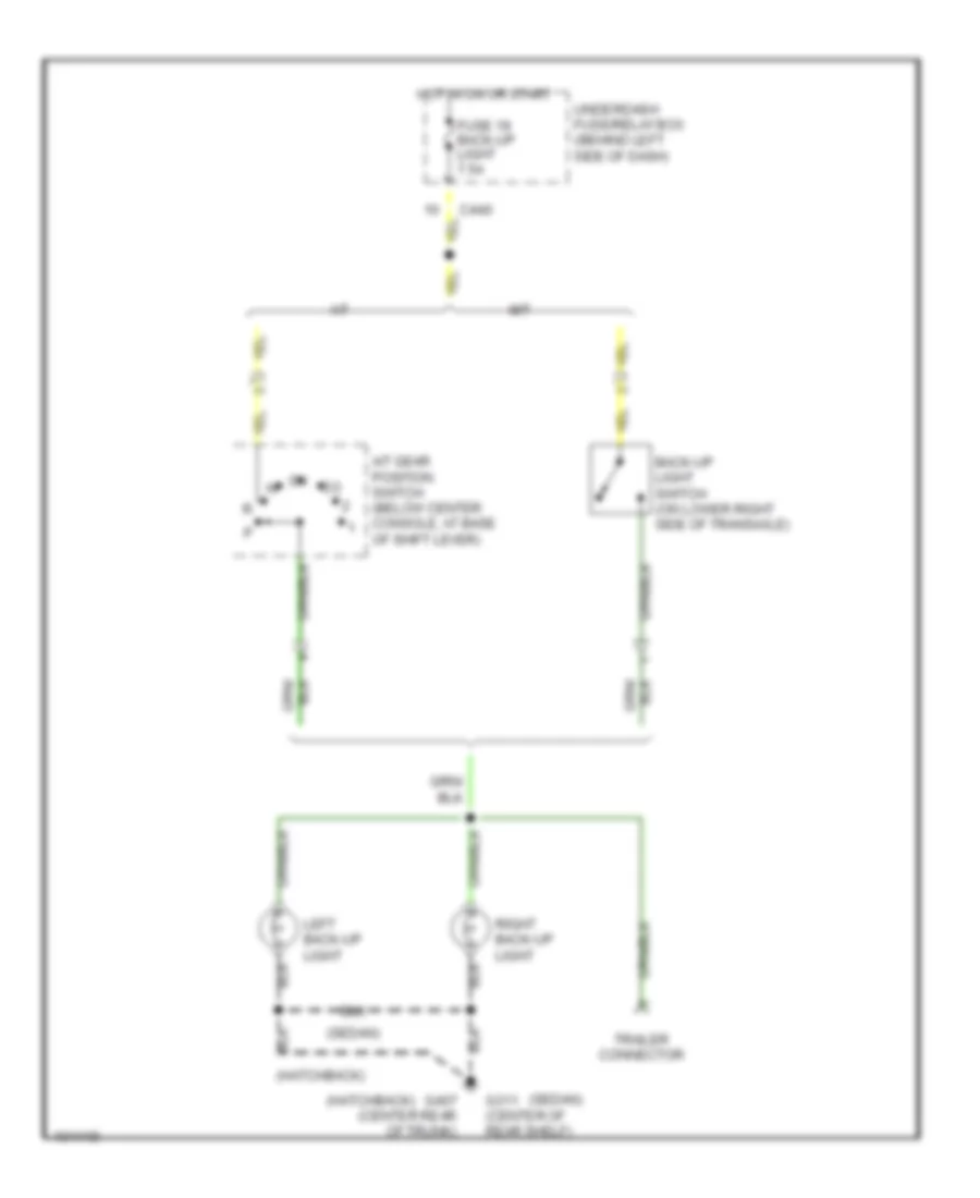
Back-up Lamps Wiring Diagram for Acura Integra GS-R 1999
List of elements for Back-up Lamps Wiring Diagram for Acura Integra GS-R 1999:
- (hatchback)
- (sedan)
- A/t
- A/t gear position switch (below center console, at base of shift lever)
- Back-up light switch (on lower right side of transaxle)
- C440
- Fuse 19 back-up light 7.5a
- G311 (center of rear shelf)
- G407 (center rear of trunk)
- Hot in on or start
- Left back-up light
- M/t
- Right back-up light
- Trailer connector
- Underdash fuse/relay box (behind left side of dash)
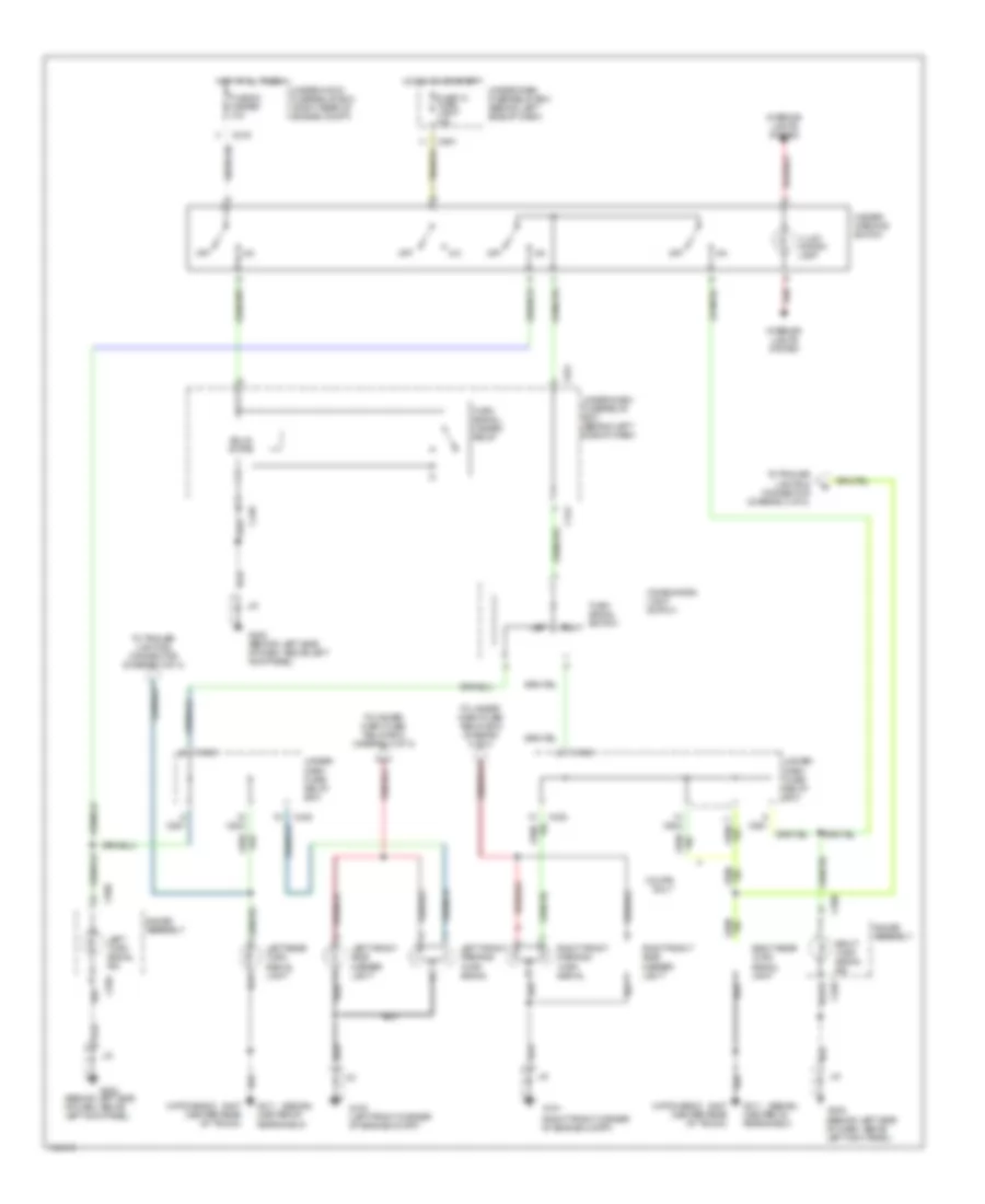
Exterior Lamps Wiring Diagram (1 of 3) for Acura Integra GS-R 1999
List of elements for Exterior Lamps Wiring Diagram (1 of 3) for Acura Integra GS-R 1999:
- (behind left side of dash, above left kick panel)
- (hatchback)
- (right front corner of engine compt)
- (sedan)
- C216
- C438
- C439
- C442
- C504
- C551
- C559
- C560
- Combination light switch
- Coupe only
- Fuse 12 turn light 10a
- Fuse 53 hazard 10a
- G100 (left front corner of engine compt)
- G101
- G202
- G202 (behind left side of dash, above left kick panel)
- G311 (center of rear shelf)
- G407 (center rear of trunk)
- Gauge assembly
- Hazard warning switch
- Hot at all times
- Hot in on or start
- Illum- ination lamp
- Interior lights system
- J/c
- Left
- Left front parking/ turn signal
- Left front side marker light
- Left rear turn signal light
- Left turn signal ind
- Off
- Red
- Right
- Right front parking/ turn signal
- Right front side marker light
- Right rear turn signal light
- Right turn signal ind
- Solid state
- To trailer lighting connector (diagram 2 of 3)
- To under- dash fuse/ relay box (diagram 2 of 3)
- Turn signal switch
- Turn signal/ hazard relay
- Under- dash fuse/ relay box
- Under-dash fuse/relay box (behind left side of dash)
- Under-hood fuse/relay box (right rear of engine compt)
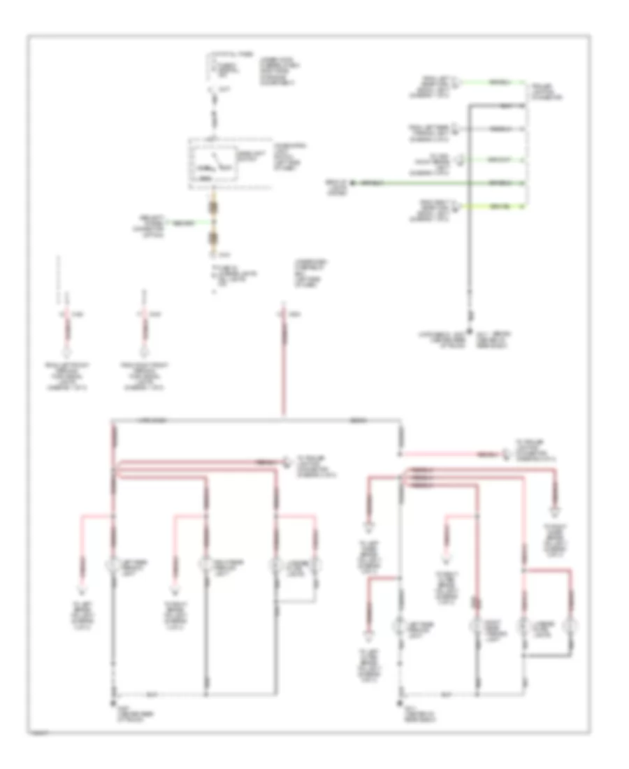
Exterior Lamps Wiring Diagram (2 of 3) for Acura Integra GS-R 1999
List of elements for Exterior Lamps Wiring Diagram (2 of 3) for Acura Integra GS-R 1999:
- (hatchback)
- (sedan)
- Back-up lights system
- C217
- C440
- C441
- C504
- Combination light switch (left side of dash)
- From left front parking/ turn signal lights (diagram 1 of 3)
- From left rear parking light (diagram 2 of 3)
- From left rear turn a signal light (diagram 1 of 3)
- From right front parking/ turn signal lights (diagram 1 of 3)
- From right rear turn b signal light (diagram 1 of 3)
- Fuse 32 license lights tail lights 10a
- Fuse 51 +b small 15a
- G311 (center of rear shelf)
- G407 (center rear of trunk)
- Hatchback
- Head
- Headlight switch
- Hot at all times
- Left rear parking light
- License plate lights
- Off
- Park
- Right rear parking light
- Security system connector (option)
- Sedan
- To high mount brake light (diagram 3 of 3)
- To left brake/ taillight (diagram 3 of 3)
- To left inner brake/ taillight (diagram 3 of 3)
- To left outer brake/ taillight (diagram 3 of 3)
- To right brake/ taillight (diagram 3 of 3)
- To right inner brake/ taillight (diagram 3 of 3)
- To right outer brake/ taillight (diagram 3 of 3)
- To trailer lighting connector (diagram 2 of 3)
- Trailer lighting connector
- Under-dash fuse/relay box (left side of dash)
- Under-hood fuse/relay box (right side of engine comartment)
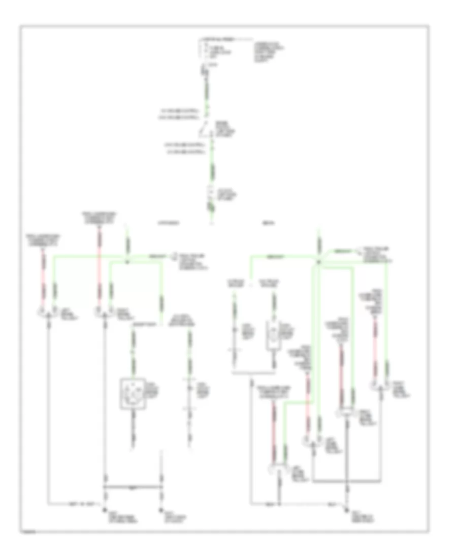
Exterior Lamps Wiring Diagram (3 of 3) for Acura Integra GS-R 1999
List of elements for Exterior Lamps Wiring Diagram (3 of 3) for Acura Integra GS-R 1999:
- (w/ cruise control)
- (w/o cruise control)
- Brake switch (left side of dash)
- C216
- Except gs-r
- From trailer lighting connector (diagram 2 of 3)
- From under-dash fuse/relay box (diagram 2 of 3)
- Fuse 52 horn, stop 20a
- G311 (center of rear shelf)
- G407 (center rear of cargo area)
- G410 (right side of hatch)
- Hatchback
- High mount brake light
- Hot at all times
- J/c c418 (left side of dash)
- Left brake/ taillight
- Left inner brake/ taillight
- Left outer brake/ taillight
- Right brake/ taillight
- Right inner brake/ taillight
- Right outer brake/ taillight
- Sedan
- Under-hood fuse/relay box (right side of engine compt)
- W/ hatch spoiler or gs-r package
- W/ trunk spoiler
- W/o trunk spoiler
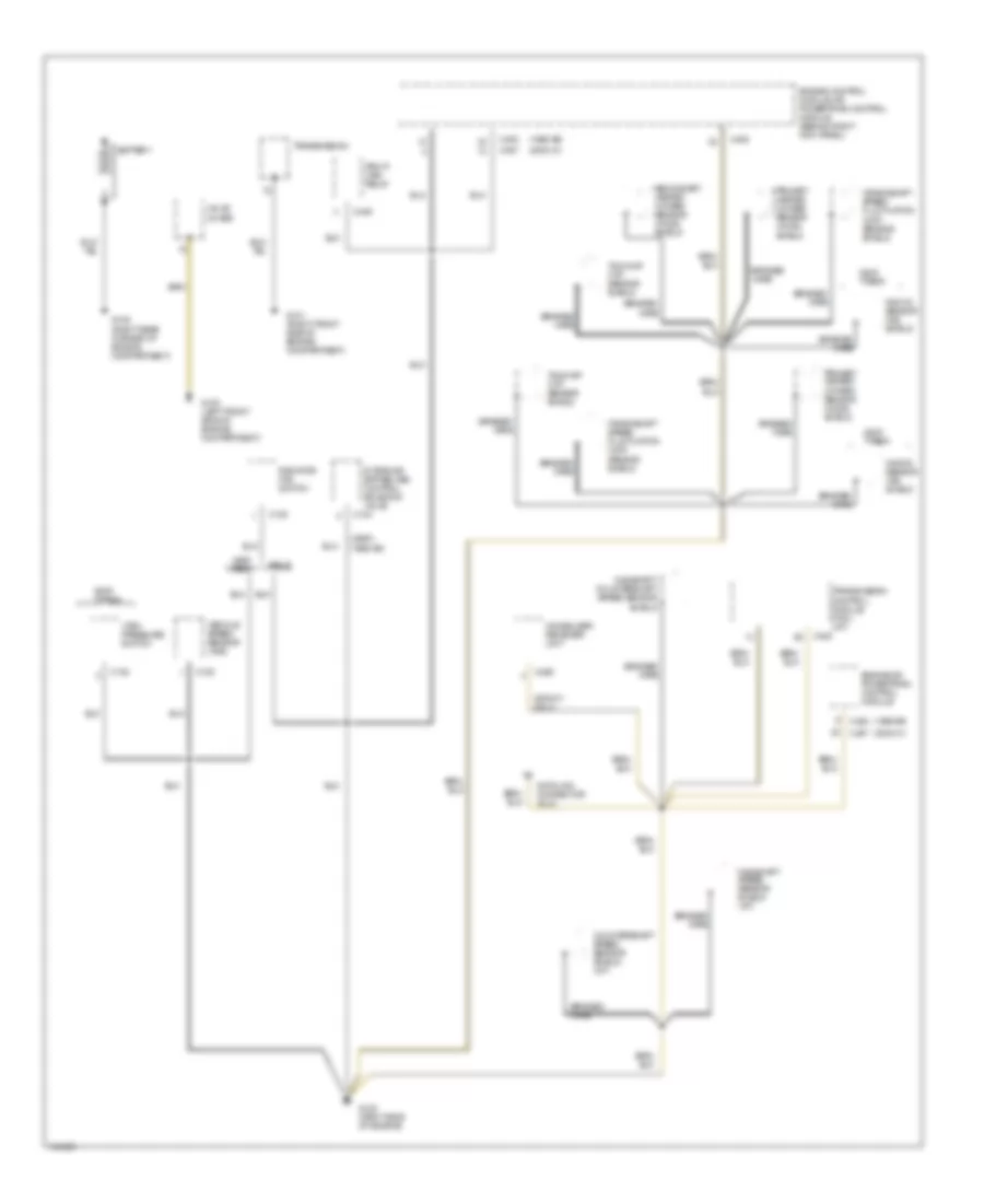
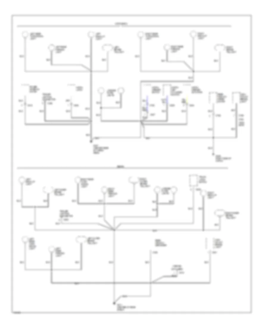
GROUND DISTRIBUTION
Ground Distribution Wiring Diagram (1 of 5) for Acura Integra GS-R 1999
List of elements for Ground Distribution Wiring Diagram (1 of 5) for Acura Integra GS-R 1999:
- (1998-99)
- (2000-01 only)
- (2000-01)
- (gs-r) (1998-99)
- Battery
- Braided
- Braided wire
- C108
- C132
- C134
- C408
- C420
- C446
- C456
- C457
- Countershaft speed sensor shield (a/t)
- Crankshaft speed fluctuation (ckf) sensor shield
- Data link connector (dlc)
- Engine control module or powertrain control module (behind right kick panel)
- Engine or powertrain control module
- G100 (left front side of engine compartment)
- G101 (right front side of engine compartment)
- G105 (right rear corner of engine compartment)
- G120 (right side of engine)
- Gs-r type r
- Immobilizer receiver unit
- Intake air bypass (iab) control solenoid valve
- Knock sensor (ks) shield
- Mainshaft speed sensor shield (a/t)
- Mainshaft/ countershaft speed sensor shield
- Pgm-fi main relay
- Primary heated oxygen sensor (ho2s) shield
- Radiator fan switch
- Rs/ls
- Secondary heated oxygen sensor (ho2s) shield
- Tdc/ckp/ cyp sensor shield
- Transmission
- Transmission control module (tcm) (a/t)
- Valve cover
- Vehicle speed sensor (vss)
- Vtec pressure switch
- Wire
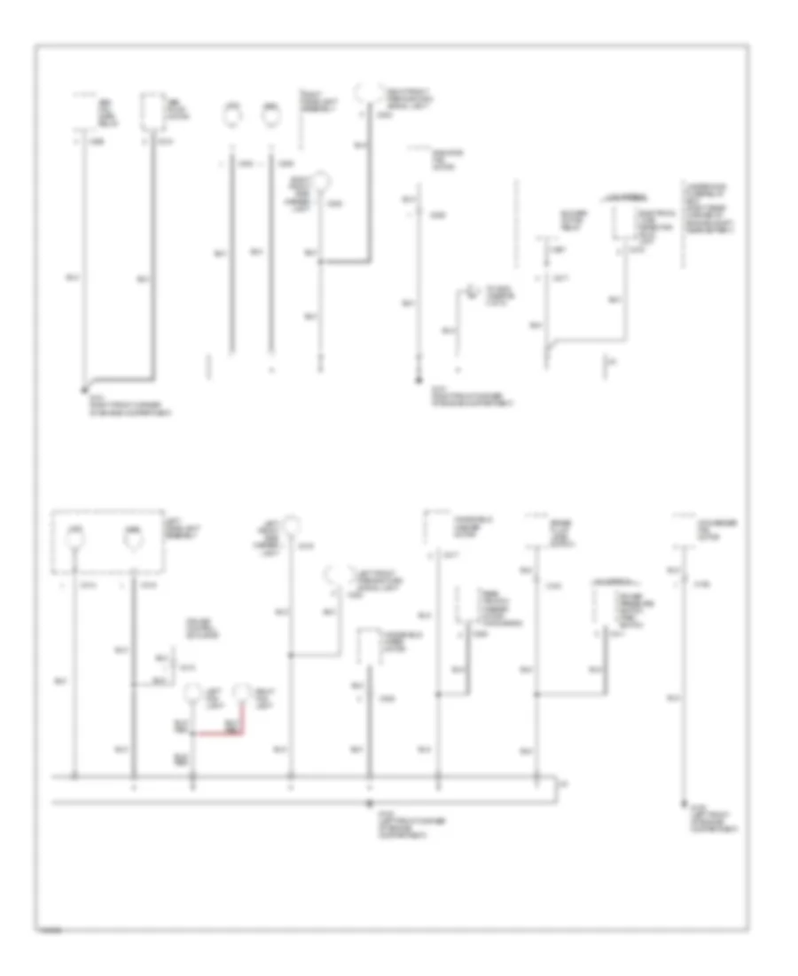
Ground Distribution Wiring Diagram (2 of 5) for Acura Integra GS-R 1999
List of elements for Ground Distribution Wiring Diagram (2 of 5) for Acura Integra GS-R 1999:
- Abs fail- safe relay
- Abs pump motor
- Blower motor relay
- Brake fluid level switch
- C155
- C202
- C203
- C204
- C205
- C206
- C208
- C210
- C217
- C218
- C308
- C310
- C311
- C313
- C314
- C315
- C317
- C319
- C320
- C907
- Condenser fan motor
- Cruise control actuator
- Electrical load detector (eld) unit
- G100 (left front corner of engine compartment)
- G101 (right front corner of engine compartment)
- G108 (left front of engine compartment)
- High
- J/c
- Left fog light
- Left front parking/turn signal light
- Left front side marker
- Left headlight assembly
- Light
- Low
- Power pressure switch (psp) switch
- Radiator fan motor
- Rear window washer motor (hatchback)
- Right fog light
- Right front parking/turn signal light
- Right front side marker
- Right headlight assembly
- To g202 (diagram 4 of 5)
- U.s. models
- Underhood fuse/relay box (right rear corner of engine compt, near battery)
- Windshield washer motor
- Windshield wiper motor
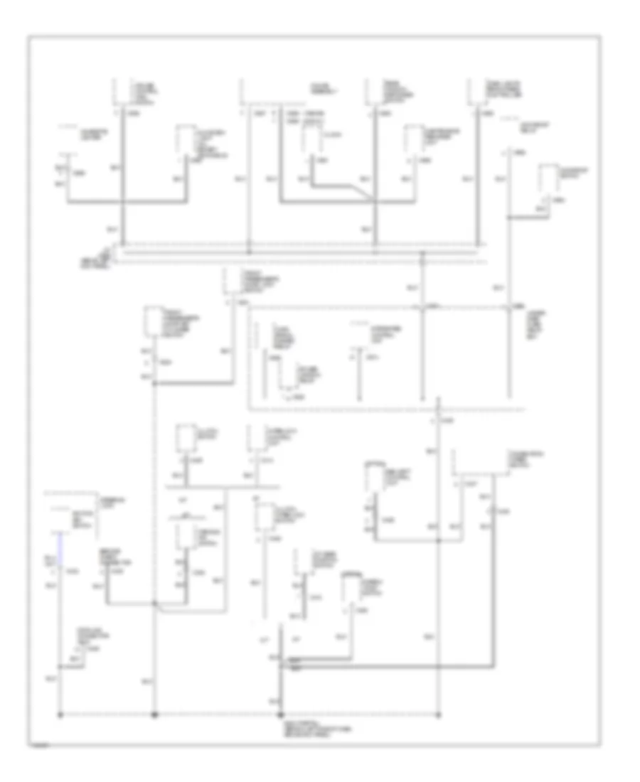
Ground Distribution Wiring Diagram (3 of 5) for Acura Integra GS-R 1999
List of elements for Ground Distribution Wiring Diagram (3 of 5) for Acura Integra GS-R 1999:
- (1998-99)
- (2000-01)
- (option)
- A/t
- A/t gear position switch
- C405
- C406
- C413
- C414
- C426
- C428
- C429
- C432
- C435
- C437
- C439
- C450
- C453
- C551
- C555
- C557
- C559
- C561
- C562
- C564
- C565
- C568
- C569
- C631
- C634
- C661
- C662
- C664
- C914
- C925
- C926
- Cigarette lighter
- Clock
- Clutch interlock switch
- Clutch switch
- Combination wiper switch
- Cruise control main switch
- Dash lights brightness controller
- Data link connector (dlc)
- Disarm/ valet switch
- Front passenger's door key cylinder switch
- Front passenger's door lock switch
- G202 (partial) (behind left side of dash, above kick panel)
- Gauge assembly
- Glove box light (all except rs models)
- Ignition key switch
- Integrated control unit
- Interlock control unit
- J/c c556 (above left kick panel)
- M/t
- Maintenance reminder unit
- Moonroof relay
- Moonroof switch
- Parking pin switch
- Power window relay
- Rear window defogger switch
- Security control unit
- Service check connector
- Steering lock
- Turn signal/ hazard relay
- Under- dash fuse/ relay box
Ground Distribution Wiring Diagram (4 of 5) for Acura Integra GS-R 1999
List of elements for Ground Distribution Wiring Diagram (4 of 5) for Acura Integra GS-R 1999:
- 2 of 5)
- Abs control unit
- C416
- C417
- C511
- C566
- C604
- C607
- C608
- C609
- C610
- C611
- C612
- C682
- C683
- C684
- C703
- C704
- C771
- C791
- C804
- Canadian models
- Cruise control unit
- Daytime running lights control unit
- Driver's door key cylinder switch (all except rs models)
- Driver's door lock actuator
- Driver's door lock switch
- Driver's seat belt switch
- From ground g101 (diagram
- Fuel pump
- Fuel tank unit
- G202 (partial) (behind left side of dash, above kick panel)
- G206 (behind center of dash)
- G206 (left lower center of dash)
- G300 (below driver's seat)
- G401 (right quarter panel)
- G411 (on left side of hatch)
- Hatchback
- Heater control panel
- Heater fan switch
- Mode control motor
- Power door lock control unit
- Power mirror switch
- Power window master switch
- Rear window defroster
- Sedan
- Srs unit
- Stereo/radio cassette player
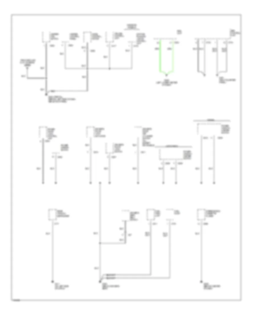
Ground Distribution Wiring Diagram (5 of 5) for Acura Integra GS-R 1999
List of elements for Ground Distribution Wiring Diagram (5 of 5) for Acura Integra GS-R 1999:
- (1998-99)
- (gs & gs-r)
- (not used)
- C518
- C520
- C524
- C527
- C528
- C529
- C531
- C533
- C535
- C755
- C756
- C758
- C763
- G311 (center of rear shelf)
- G406 (right side of hatch)
- G407 (center rear of cargo area)
- Hatch key cylinder switch
- Hatch latch
- Hatch opener actuator
- Hatch opener switch
- Hatchback
- High mount brake light
- Left back-up light
- Left brake/ taillight
- Left inner brake/ taillight
- Left outer brake/ taillight
- Left rear parking light
- Left rear turn signal light
- License plate lights
- Power antenna motor
- Rear window defogger
- Rear window wiper motor
- Right back-up light
- Right brake/ taillight
- Right inner brake/ taillight
- Right outer brake/ taillight
- Right rear parking light
- Right rear turn signal light
- Sedan
- Trailer lighting connector
- Trunk latch switch
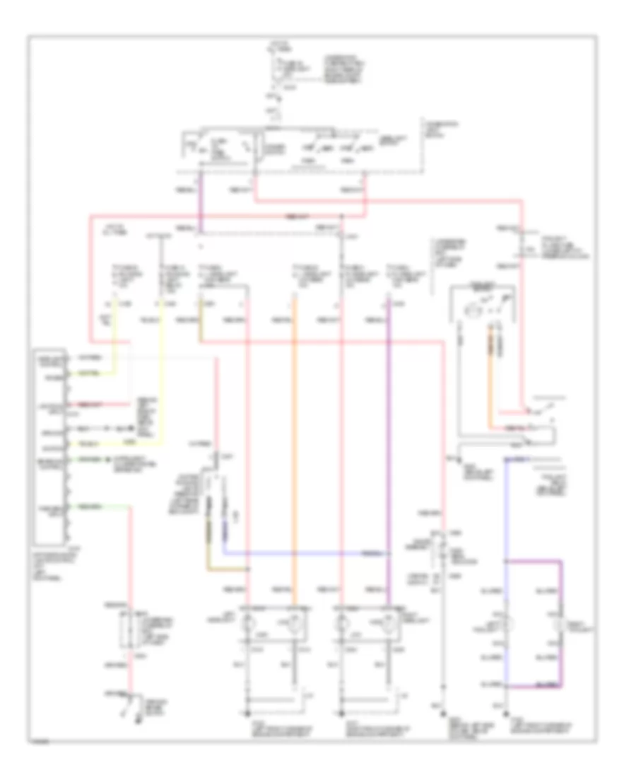
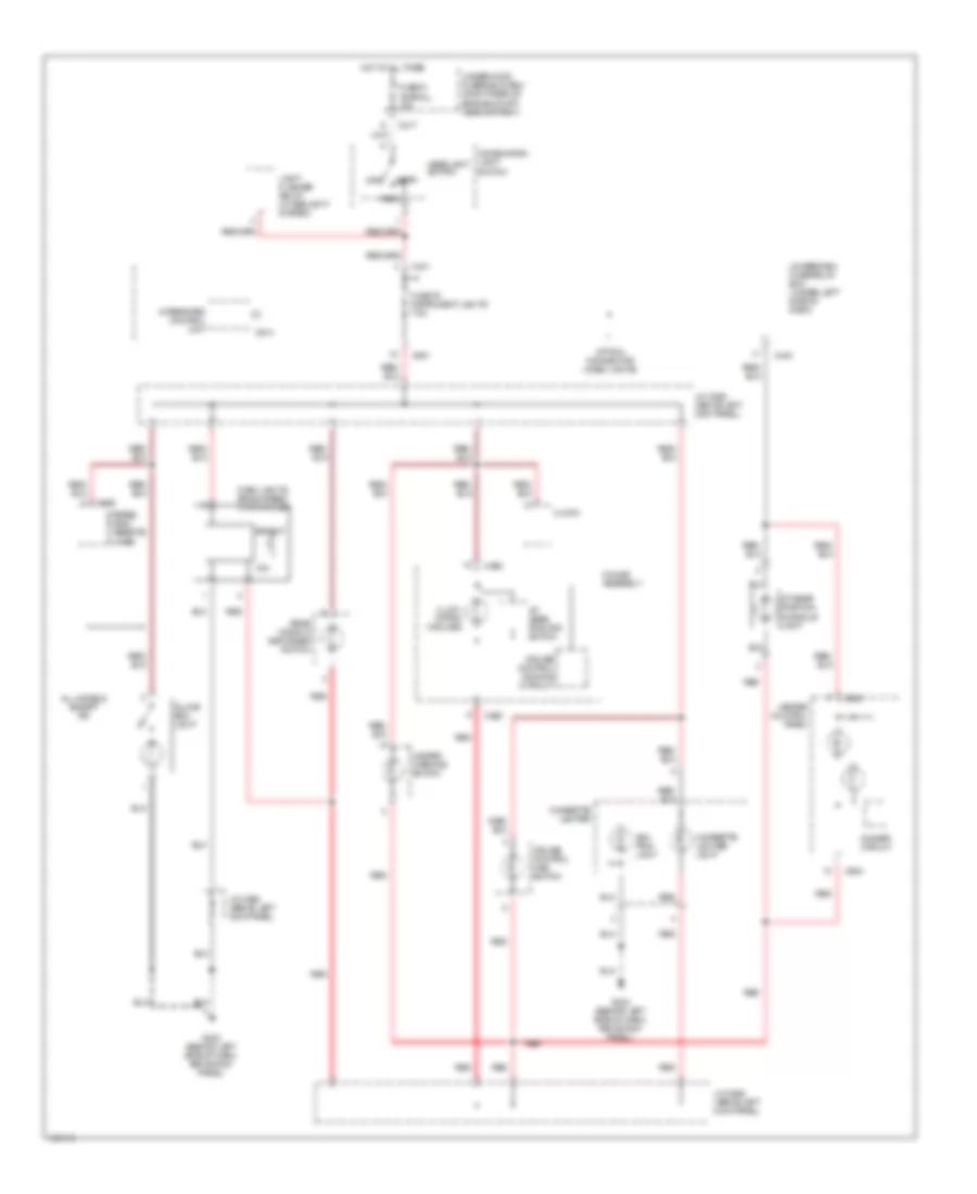
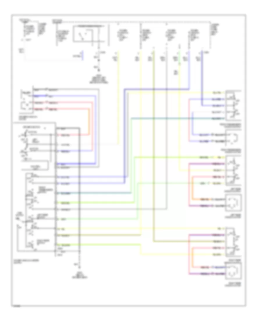
HEADLIGHTS
Headlamps & Fog Lamps Wiring Diagram, with DRL for Acura Integra GS-R 1999
List of elements for Headlamps & Fog Lamps Wiring Diagram, with DRL for Acura Integra GS-R 1999:
- (1998-99)
- (2000-01)
- (behind left side of dash, above kick panel)
- 15a
- B15
- Brake ind control
- C204
- C205
- C216
- C307
- C314
- C315
- C416
- C438
- C439
- C440
- C441
- C504
- C551
- C559
- C560
- Combination light switch
- Control
- Daytime running lights control unit (left kick panel)
- Daytime running lights resistor (left rear corner of eng compt)
- Dimmer switch
- Flash- to- pass switch
- Foglight in-line fuse (lower left of steering column)
- Foglight relay (above left kick panel)
- Foglight switch
- Fuse 18 (running light relay) 7.5a
- Fuse 20 (running light) 10a
- Fuse 21 r. headlight low beam 10a
- Fuse 22 l. headlight low beam 10a
- Fuse 4 r. headlight high beam 10a
- Fuse 48 headlight 40a
- Fuse 5 l. headlight high beam 10a
- G100 (left front corner of engine compartment)
- G101 (right front corner of engine compartment)
- G200 (above left kick panel)
- G202
- G202 (behind left side of dash, above kick panel)
- Gauge assembly
- Ground
- Head
- Headlamp
- Headlight switch
- High
- High beam indicator
- Hot at all times
- Hot in on
- Ignition
- Instrument cluster system (brake ind)
- J/c
- Left foglight
- Left headlight
- Lights on input c415
- Low
- Nca
- Off
- Park
- Park brk input
- Parking brake switch
- Power
- Right foglight
- Right headlight
- Underdash fuse/relay box (left side of dash)
- Underhood fuse/relay box (right rear of engine compt, near battery)
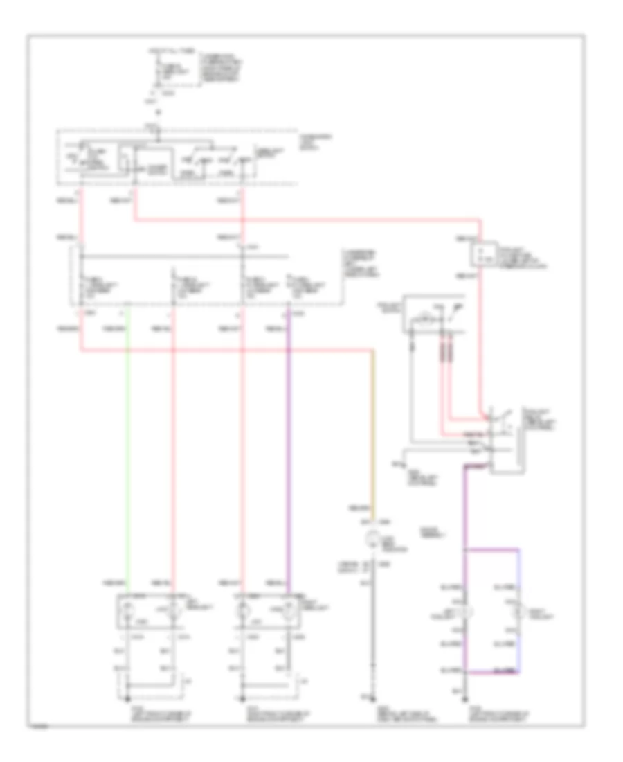
Headlamps & Fog Lamps Wiring Diagram, without DRL for Acura Integra GS-R 1999
List of elements for Headlamps & Fog Lamps Wiring Diagram, without DRL for Acura Integra GS-R 1999:
- (1998-99)
- (2000-01)
- 15a
- B15
- C204
- C205
- C216
- C314
- C315
- C438
- C441
- C551
- C559
- C560
- Combination light switch
- Dimmer switch
- Flash- to- pass switch
- Foglight in-line fuse (lower left of steering column)
- Foglight relay (above left kick panel)
- Foglight switch
- Fuse 21 r. headlight low beam 10a
- Fuse 22 l. headlight low beam 10a
- Fuse 4 r. headlight high beam 10a
- Fuse 48 headlight 40a
- Fuse 5 l. headlight high beam 10a
- G100 (left front corner of engine compartment)
- G101 (right front corner of engine compartment)
- G200 (above left kick panel)
- G202 (behind left side of dash, above kick panel)
- Gauge assembly
- Head
- Headlight switch
- High
- High beam indicator
- Hot at all times
- J/c
- Left foglight
- Left headlight
- Low
- Nca
- Off
- Park
- Right foglight
- Right headlight
- Underdash fuse/relay box (under left side of dash)
- Underhood fuse/relay box (right rear of engine compt, near battery)
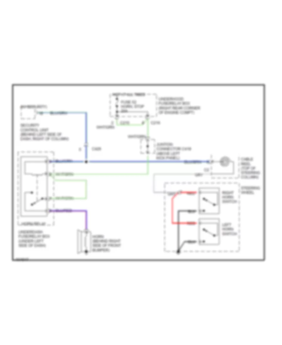
HORN
Horn Wiring Diagram for Acura Integra GS-R 1999
List of elements for Horn Wiring Diagram for Acura Integra GS-R 1999:
- (w/ security)
- C215
- C216
- C426
- Cable reel (top of steering column)
- Fuse 52 horn, stop 20a
- Horn (behind right side of front bumper)
- Horn relay
- Hot at all times
- Juntion connector c418 (above left kick panel)
- Left horn switch
- Red
- Right horn switch
- Security control unit (behind left side of dash, right of column)
- Steering wheel
- Underdash fuse/relay box (under left side of dash)
- Underhood fuse/relay box (right rear corner of engine compt)
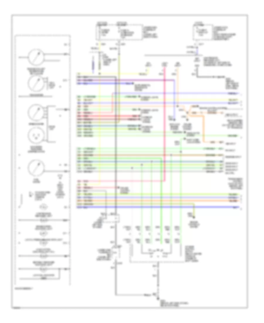
INSTRUMENT CLUSTER
Instrument Cluster Wiring Diagram (1 of 2) for Acura Integra GS-R 1999
List of elements for Instrument Cluster Wiring Diagram (1 of 2) for Acura Integra GS-R 1999:
- A/t gear position switch (below center console, at base of shift lever)
- A10
- A11
- A17
- Anti-lock brakes system
- B10
- B11
- B13
- B14
- B15
- B16
- Bat input
- Brake system indicator light
- C10
- C217
- C439
- C551
- Cruise control system
- D11
- D12
- D13
- Drive ckt.
- Drive input
- Engine controls system
- Engine coolant temperature (ect) gauge
- Exterior lights system
- Fuel gauge
- Fuse 15 alternator sp sensor 7.5a
- Fuse 25 meter 7.5a
- Fuse 47 back-up 7.5a
- G202 (behind left side of dash, above kick panel)
- Gauge assembly
- Gnd
- Headlights system
- Hot at all times
- Hot in on or start
- Ign input
- Ind ctrl
- Interior lights system
- J/c c556 (under left side of dash)
- Light ctrl
- Low fuel indicator light
- Low oil pressure indicator light
- Maintenance reminder light
- Maintenance reminder unit (on rear of left side of dashboard lower cover)
- Malfunction indicator light (mil)
- Odometer/ tripmeter stepper motor
- P/n input
- Pnk
- Red
- Reverse input
- Seat belt reminder indicator light
- Shift inter- lock system
- Speedometer
- Tach. drive ckt.
- Tachometer
- To door open indicator (diagram 2 of 2)
- To right turn indi- cator (diagram 2 of 2)
- Transmission control module (tcm) (behind left kick panel)
- Under-dash fuse/relay box (under left side of dash)
- Under-hood fuse/relay box (right rear corner of engine compt, near battery)
- Vehicle speed sensor (vss) (on top left front of transaxle)
- Vss input
- Vss output
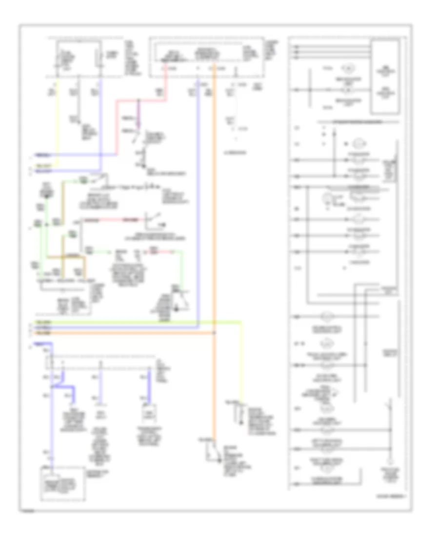
Instrument Cluster Wiring Diagram (2 of 2) for Acura Integra GS-R 1999
List of elements for Instrument Cluster Wiring Diagram (2 of 2) for Acura Integra GS-R 1999:
- (diagram 1 of 2)
- (not used)
- 1 indicator
- 2 indicator
- A/t gear position indicator
- Abs indicator ckt
- Abs indicator light
- Alternator
- Anti- lock brakes system
- B10
- B11
- B13
- B14
- B15
- Brake bulb check ckt
- Brake fluid level switch (on bottom of brake fluid reservoir cap)
- Brake ind ctrl
- C10
- C119
- C438
- C440
- C449
- C504
- C551
- Canada
- Charging system indicator light
- Cruise control indicator light
- Cruise control unit (under left side of dash, above underdash fuse/relay box)
- Cruise ctrl dim- ming ckt
- D3 indicator
- D4 indicator
- Daytime running lights control unit (behind left side kick panel, above underdash fuse/ relay box)
- Dimming circuit
- Dimming ckt.
- Distributor assembly
- Door open indicator light
- Driver's seat belt switch
- Engine coolant temperature (ect) gauge sending unit (on rear of cylinder head)
- Engine oil pressure ind flasher ckt
- Engine oil pressure switch (lower left side of engine, left of oil filter)
- Engine speed output
- From fuel gauge (diagram 1 of 2)
- From maintenance reminder light b
- Fuel gauge send- ing unit
- Fuel tank unit (in fuel tank, under access cover in trunk)
- G100 (left front corner of engine compt)
- G300 (below driver's seat)
- Gauge assembly
- High beam indicator light
- Ignition control module (icm)
- Illum (3 bulbs)
- Inte- grated control unit
- J/c c418 (behind left kick panel)
- Key-in seat belt reminder ckt
- Left turn signal indicator light
- N indicator
- P indicator
- P.b.
- Park brake switch (on base of parking brake lever)
- Parking brake switch (on base of parking brake lever)
- R indicator
- Right turn signal indicator light
- Rpm input
- Srs indicator ckt
- Srs indicator light
- Sw in
- Test tachometer connector (left rear corner of engine compt)
- Therm- istor
- Transmission control module (tcm) (behind left kick panel)
- Trunk lid/hatch open indicator light
- Under dash- fuse/ relay box
- Under- dash fuse/ relay box
- Usa
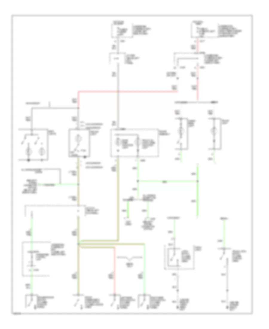
INTERIOR LIGHTS
Courtesy Lamps Wiring Diagram for Acura Integra GS-R 1999
List of elements for Courtesy Lamps Wiring Diagram for Acura Integra GS-R 1999:
- (center of rear shelf) g311
- (center rear of cargo area) g407
- (not used)
- (w/moonroof)
- (w/o moonroof)
- All models except usa rs
- All models except usa rs model
- C217
- C426
- C439
- C440
- C449
- C504
- C551
- C559
- C560
- Cargo area light
- Ceiling light
- Door
- Door open indicator light
- Driver's door switch (closed w/door open)
- Front passenger's door switch (closed w/door open)
- Fuse 25 meter 7.5a
- Fuse 43 interior light fuse 7.5a
- Gauge assembly
- Hatch latch
- Hatchback
- Hot at all times
- Hot in on or start
- Integrated control unit
- J/c c418 (above left kick panel)
- J/c c556 (above left kick panel)
- Latch switch (closed w/hatch open)
- Left rear door switch (closed w/door open)
- Off
- Right rear door switch (closed w/door open)
- Security system connector (option)
- Security system connector (option) (below left side of dash)
- Sedan
- Sedan only
- Spot lights
- Trunk latch switch (closed w/trunk open)
- Trunk lid/ hatch open indicator light
- Trunk light
- Underdash fuse/relay box (under left side of dash)
- Underhood fuse/relay box (right rear corner of engine compt, near battery)
- Usa rs model
- W/moonroof
Instrument Illumination Wiring Diagram for Acura Integra GS-R 1999
List of elements for Instrument Illumination Wiring Diagram for Acura Integra GS-R 1999:
- A/t gear position console light
- A/t gear position switch
- All models except rs
- Ash tray light
- Bright
- C217
- C440
- C441
- C551
- C560
- C566
- C684
- C914
- Cigarette lighter
- Cigarette lighter light
- Clock
- Combination light switch
- Cruise control dimming citrcuit
- Cruise control main switch
- Dash lights brightness controller
- Dim
- Dimmer circuit
- Fuse 30 instrument lights 7.5a
- Fuse 51 +b small 15a
- G202 (behind left side of dash, above kick panel)
- Gauge assembly
- Glove box light
- Hazard warning switch
- Head
- Headlight switch
- Heater control panel
- Hot at all times
- Illumi- nation (3 bulbs)
- Integrated control unit
- J/c c556 (above left kick panel)
- Light flasher relay (w/ security system)
- Off
- Option connector (dash lights)
- Park
- Rear window defogger switch
- Red
- Stereo radio/ cassette player
- Underdash fuse/relay box (under left side of dash)
- Underhood fuse/relay box (right rear of engine compt, near battery)
POWER ANTENNA
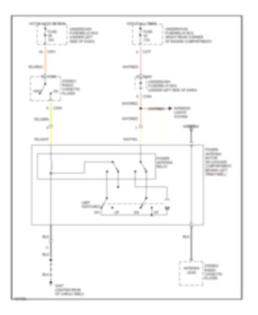
Power Antenna Wiring Diagram for Acura Integra GS-R 1999
List of elements for Power Antenna Wiring Diagram for Acura Integra GS-R 1999:
- Antenna
- Antenna lead
- C217
- C440
- C504
- C551
- C556
- C566
- Fuse 10a
- Fuse 7.5a
- G407 (center rear of cargo area)
- Hot at all times
- Hot in accy or run
- Interior lights system
- Limit switches
- Off
- Power antenna motor (in luggage compartment, behind left trim panel)
- Power antenna relay
- Stereo radio/ cassette player
- Underdash fuse/relay box (under left side of dash)
- Underhood fuse/relay box (right rear corner of engine compartment)
POWER DISTRIBUTION
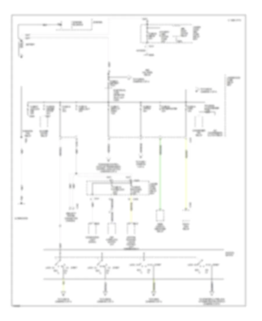
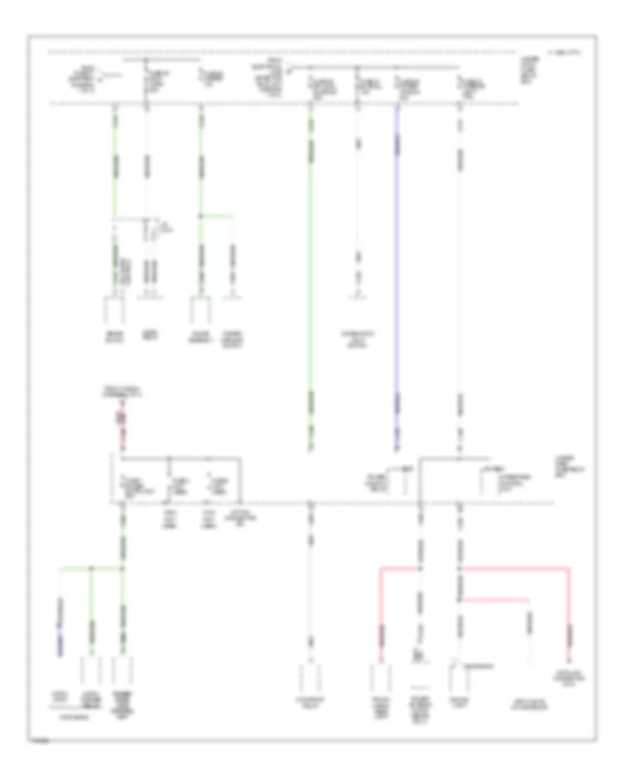
Power Distribution Wiring Diagram (1 of 4) for Acura Integra GS-R 1999
List of elements for Power Distribution Wiring Diagram (1 of 4) for Acura Integra GS-R 1999:
- (0)
- (canada)
- (i)
- (iii)
- A/c compressor clutch relay
- Abs fail-safe relay
- Abs pump motor relay
- Acc
- Alternator
- Battery
- Blower motor relay
- C 1995 vftc
- C208
- C213
- C216
- C217
- C415
- C436
- C439
- C440
- C441
- C445
- C446
- C903
- C906
- C907
- Combination light switch
- Condenser fan relay
- Daytime running lights control unit (canada only)
- Electrical load detector (eld) unit (usa)
- Fuse 20 running lights 10a
- Fuse 33 interlock unit 7.5a
- Fuse 41 battery 100a
- Fuse 42 ig 1 40a
- Fuse 44 fi e/m 15a
- Fuse 47 back up, radio 7.5a
- Fuse 48 headlight 40a
- Fuse 50 rr defroster 40a
- Fuse 54 option 40a
- Fuse 55 heater motor 40a
- Fuse 56 condenser fan 20a
- Fuse 57 cooling fan 20a
- Fuse 61 abs motor fuse 40a
- Fuse 62 abs b1 20a
- Ignition switch
- Key interlock switch (a/t)
- Lock
- On (ii)
- Pgm-fi main relay
- Radiator fan relay
- Rear window defogger relay
- Security system connector
- Start
- Starter
- Starter solenoid
- T101
- T102
- To engine control module/ transmission control module (tcm) (diagram 2 of 4)
- To fuse 1 (diagram 4 of 4)
- To fuse 16 (diagram 2 of 4)
- To fuse 28 (diagram 3 of 4)
- To fuse 49 (diagram 4 of 4)
- To fuse 52 (diagram 4 of 4)
- To fuse 9 (diagram 3 of 4)
- To starter cut relay & a/t gear positi0n switch (diagram 2 of 4)
- Under- dash fuse/ relay box
- Under- hood abs fuse/ relay box
- Underhood fuse/ relay box
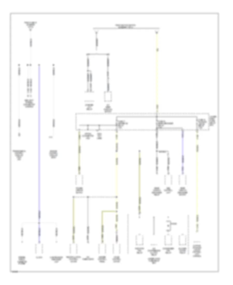
Power Distribution Wiring Diagram (2 of 4) for Acura Integra GS-R 1999
List of elements for Power Distribution Wiring Diagram (2 of 4) for Acura Integra GS-R 1999:
- A/c compressor clutch relay
- A/c thermostat
- A/t
- A/t gear position switch
- A23
- Abs control unit
- Blower motor relay
- C10
- C216
- C413
- C416
- C426
- C433
- C438
- C439
- C440
- C447
- C448
- C503
- C504 not used
- C551
- C564
- C608
- C675
- C676
- C682
- C684
- C704
- C922
- Clock
- Condenser fan relay
- Daytime running lights control unit (canada)
- Diode
- Engine control module (ecm)
- From fuse 47 (diagram 1 of 4)
- From ignition switch (diagram 1 of 4)
- Fuse 16 rear defogger relay 7.5a
- Fuse 17 heater a/c relay 7.5a
- Fuse 18 running lights relay 7.5a
- Heater control panel
- M/t
- Maintenance reminder unit
- Mode control motor
- Option connector (ig2)
- Power mirror switch
- Radiator fan relay
- Rear window defogger relay
- Rear window defogger switch
- Recirculation control motor
- Security system connector (canada)
- Starter cut relay
- Stereo radio/ cassette player
- Transmission control module (tcm) (a/t)
- Under- dash fuse/ relay box
- Under-hood fuse/relay box
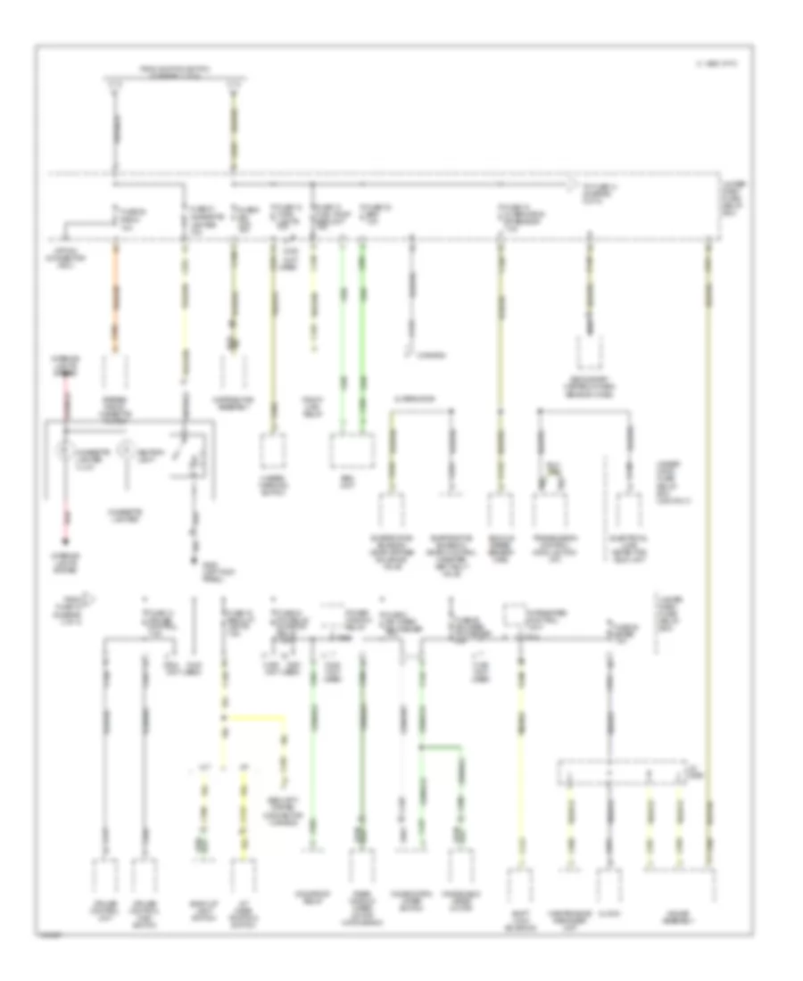
Power Distribution Wiring Diagram (3 of 4) for Acura Integra GS-R 1999
List of elements for Power Distribution Wiring Diagram (3 of 4) for Acura Integra GS-R 1999:
- (canada)
- (not used)
- 10a
- A/t
- A/t gear position switch
- A12
- A25
- Alternator
- Ashtray light
- Back-up light switch
- C 1995 vftc
- C108
- C112
- C119
- C218
- C224
- C308
- C412
- C413
- C417
- C426
- C435
- C437
- C438
- C438 (not used)
- C439
- C440
- C440 c440 c440
- C442
- C443
- C446
- C504
- C551
- C555
- C557
- C559
- C560
- C561
- C563
- C566
- C568
- C661
- C662
- C793
- C801
- C804
- C914
- C922
- C925 c925 c925
- Cigarette lighter
- Cigarette lighter illum
- Clock
- Combination wiper switch
- Cruise control main switch
- Cruise control unit
- Distributor assembly
- Electrical load detector (eld) unit
- Evaporative emission (evap) bypass solenoid valve
- Evaporative emission (evap) control canister vent shut valve
- From i fuse 15 (diagram 3 of 4)
- From ignition switch (diagram 1 of 4)
- Fuse 12 turn lights 10a
- Fuse 13 fuel pump srs unit 15a
- Fuse 14 cruise control 7.5a
- Fuse 15 alternator sp sensor 7.5a
- Fuse 19 back up lights 7.5a
- Fuse 23 srs 10a
- Fuse 24 p/w relay sunroof relay 7.5a
- Fuse 25 meter 7.5a
- Fuse 26 fr wiper fr washer 20a
- Fuse 27 cigarette
- Fuse 28 radio
- Fuse 3 rr wiper rr washer 10a
- Fuse 9 ign coil 15a
- G200 (left kick panel)
- Gauge assembly
- Hazard warning switch
- Integrated control unit
- Interior lights system
- J/c c556
- Lighter 10a
- M/t
- Maintenance reminder unit
- Moonroof relay
- Option connector (acc)
- Pgm-fi main relay
- Power window relay
- Rear window wiper motor (hatchback)
- Red
- Secondary heated oxygen sensor (hos2)
- Security system connector (canada)
- Shift lock solenoid
- Srs unit
- Stereo radio/ cassette player
- To fuse 14 (diagram 3 of 4)
- Transmission control module (tcm) (a/t)
- Under- dash fuse/ relay box
- Under- hood fuse/ relay box (usa only)
- Vehicle speed sensor (vss)
- Windshield wiper motor
Power Distribution Wiring Diagram (4 of 4) for Acura Integra GS-R 1999
List of elements for Power Distribution Wiring Diagram (4 of 4) for Acura Integra GS-R 1999:
- (diagram 1 of 4)
- (moonroof)
- (not used)
- Brake switch
- C 1995 vftc
- C215
- C216
- C217
- C431
- C436
- C439
- C440
- C504
- C518
- C560
- C563
- C604 c604
- C661
- C914
- C925
- Ceiling light
- Combination light switch
- Control) (w/ cruise
- Data link connector (dlc)
- From electrical load detector (eld) unit (diagram 1 of 4)
- From fuse 41 & battery a
- From fuse 54 (diagram 1 of 4)
- Fuse 1 power door lock 20a
- Fuse 2 (not used)
- Fuse 43 interior light 7.5a
- Fuse 46 power window 40a
- Fuse 49 dr lock, sunroof 30a
- Fuse 51 b+ small 15a
- Fuse 52 stop, horn 20a
- Fuse 53 hazard 10a
- Fuse 6 (not used)
- Gauge assembly
- Hatch latch
- Hatch opener relay
- Hatchback
- Hazard warning switch
- Horn relay
- Integrated control unit
- J/c c418
- Moonroof relay
- Option connector (b+)
- Power antenna motor (sedan only)
- Power power door door lock lock control control unit unit
- Power window relay
- Spotlights (w/ moonroof)
- Trunk/ cargo area light
- Under- dash fuse/relay box
- Under- hood fuse/ relay box
POWER DOOR LOCKS
Door Lock Wiring Diagram, Hatchback for Acura Integra GS-R 1999
List of elements for Door Lock Wiring Diagram, Hatchback for Acura Integra GS-R 1999:
- (behind left side of dash, above left kick panel) g202
- Battery in
- C504
- Driver's door key cylinder switch
- Driver's door lock actuator
- Driver's door lock switch
- Driver's unlock only relay (w/ anti-theft) (in driver's door)
- Front passenger's door key cylinder switch
- Front passenger's door lock actuator
- Front passenger's door lock switch
- Fuse 1 (power door lock) 20a
- G300 (below driver's seat)
- G407 (center rear of cargo area)
- Ground
- Hatch key cylinder switch
- Hatch latch (center rear of cargo area)
- Hatch lock actuator
- Hot at all times
- Lock
- Lock in
- Lock out
- Power door lock control unit (in driver's door)
- Security control unit (w/ anti-theft) (behind left side of dash)
- Un- lock
- Underdash fuse/relay box (under left side of dash)
- Unlock
- Unlock in
- Unlock out
- W/ anti- theft
- W/o anti- theft
Door Lock Wiring Diagram, Sedan for Acura Integra GS-R 1999
List of elements for Door Lock Wiring Diagram, Sedan for Acura Integra GS-R 1999:
- (behind left side of dash, above left kick panel) g202
- Battery in
- C504
- Driver's door key cylinder switch
- Driver's door lock actuator
- Driver's door lock switch
- Driver's unlock only relay (w/ anti-theft) (in driver's door)
- Front passenger's door key cylinder switch
- Front passenger's door lock actuator
- Front passenger's door lock switch
- Fuse 1 (power door lock) 20a
- G300 (below driver's seat)
- Ground
- Hot at all times
- Left rear door lock actuator
- Lock
- Lock in
- Lock out
- Power door lock control unit (in driver's door)
- Right rear door lock actuator
- Security control unit (w/ anti-theft) (behind left side of dash)
- Un- lock
- Underdash fuse/relay box (under left side of dash)
- Unlock
- Unlock in
- Unlock out
- W/ anti- theft
- W/o anti- theft
POWER MIRRORS
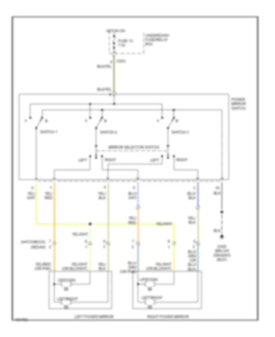
Power Mirrors Wiring Diagram for Acura Integra GS-R 1999
List of elements for Power Mirrors Wiring Diagram for Acura Integra GS-R 1999:
- (hatchback)
- (sedan)
- Fuse 13 7.5a
- G300 (below driver's seat)
- Hot in on
- Left
- Left power mirror
- Left/right
- Mirror selector switch
- Power mirror switch
- Right
- Right power mirror
- Switch 1
- Switch 2
- Switch 3
- Underdash fuse/relay box
- Up/down
POWER TOP/SUNROOF
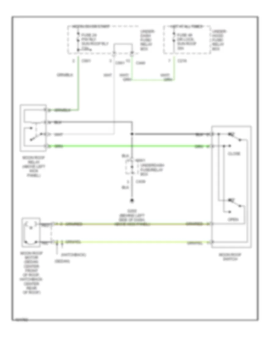
Moonroof Wiring Diagram for Acura Integra GS-R 1999
List of elements for Moonroof Wiring Diagram for Acura Integra GS-R 1999:
- (hatchback)
- (sedan)
- C216
- C439
- C440
- C661
- Close
- Fuse 24 p/w rly sun roof rly 7.5a
- Fuse 49 dr lock, sun roof 30a
- G202 (behind left side of dash, above kick panel)
- Hot at all times
- Hot in on or start
- Moon roof motor (sedan: center front of roof, hatchback: center rear of roof)
- Moon roof relay (above left kick panel)
- Moon roof switch
- Off
- Open
- Red
- Under- dash fuse/ relay box
- Under- hood fuse/ relay box
- Underdash fuse/relay box
POWER WINDOWS
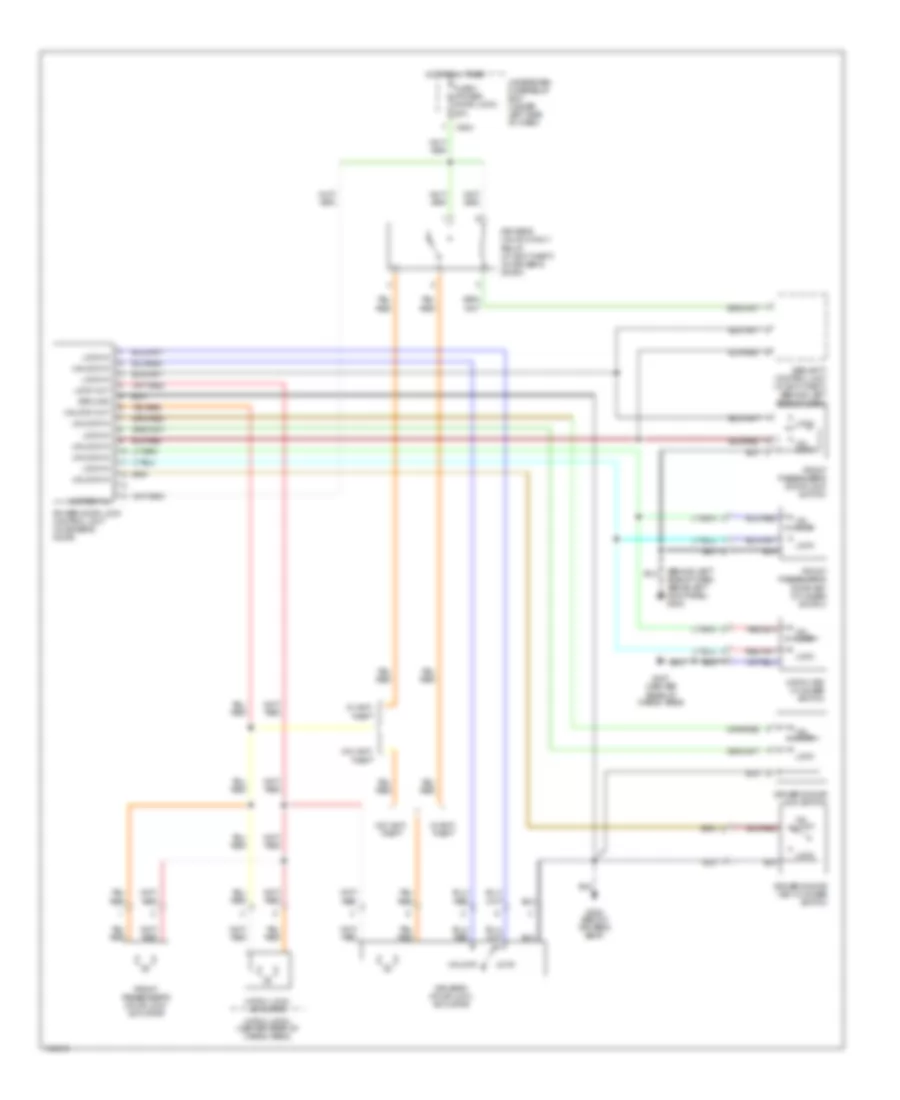
Power Windows Wiring Diagram, Hatchback for Acura Integra GS-R 1999
List of elements for Power Windows Wiring Diagram, Hatchback for Acura Integra GS-R 1999:
- (behind left side of dash, above kick panel) g202
- (below driver's seat) g300
- 20a
- 40a
- 7.5a
- Auto dn
- C217
- C439
- C503
- Control unit
- Driver's switch
- Driver's window motor
- Hot at all times
- Hot in on or start
- Main switch
- Off
- P/w relay sunroof relay fuse 24
- Passenger's switch
- Passenger's window motor
- Passenger's window switch
- Power window fr-l fuse 11
- Power window fr-r fuse 10
- Power window fuse 46
- Power window master switch
- Power window relay
- Pulser
- Under- hood fuse/ relay box
- Underdash fuse/relay box
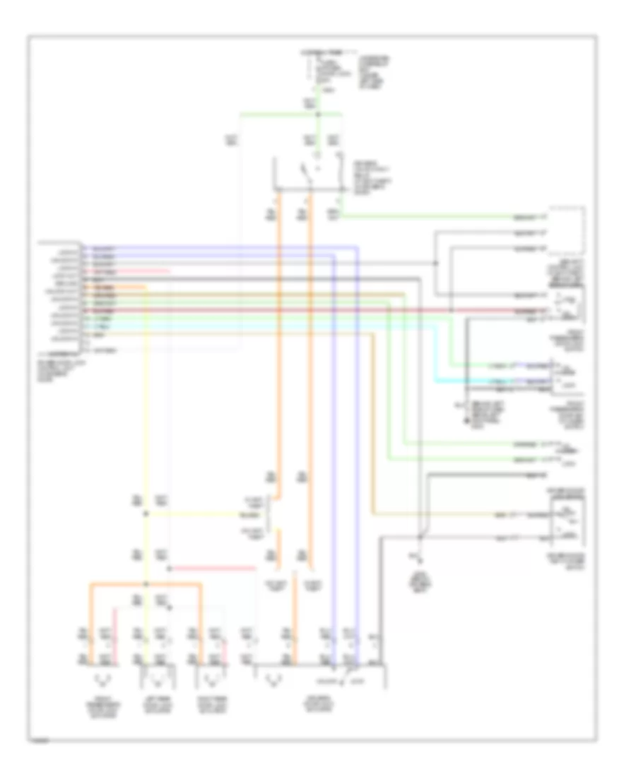
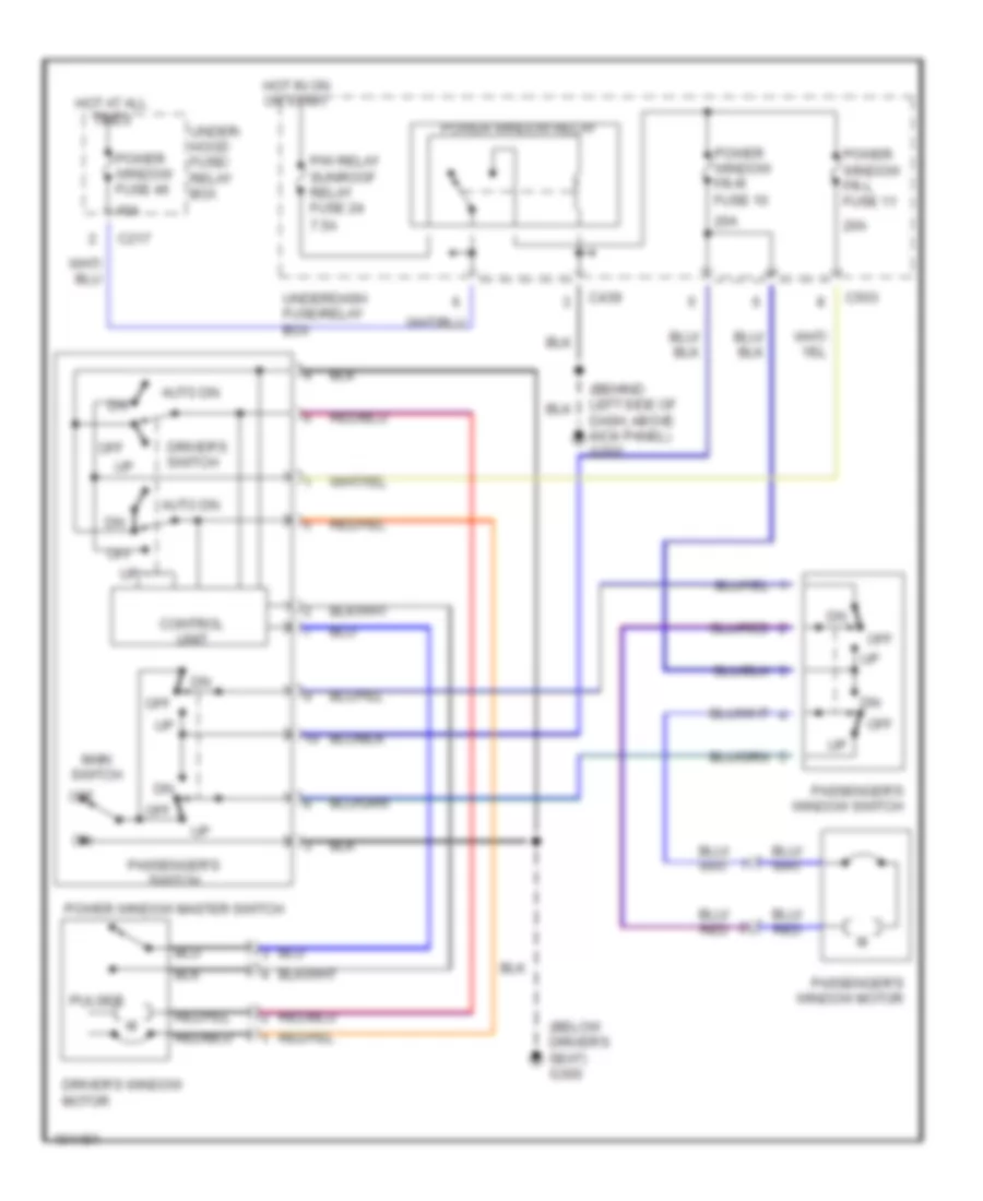
Power Windows Wiring Diagram, Sedan for Acura Integra GS-R 1999
List of elements for Power Windows Wiring Diagram, Sedan for Acura Integra GS-R 1999:
- Auto dn
- C217
- C439
- C503
- C609
- C612
- Control unit
- Driver's switch
- Driver's window motor
- Fron passenger's window motor
- Front passenger's switch
- Front passenger's window switch
- G202 (behind left side of dash, above kick panel)
- G300 (below driver's seat)
- Hot at all times
- Hot in on or start
- Left front
- Left rear switch
- Left rear window motor
- Left rear window switch
- Main switch
- Off
- P/w relay sunroof relay fuse 24 7.5a
- Power window fr-l fuse 11 20a
- Power window fr-r fuse 10 20a
- Power window fuse 46 40a
- Power window master switch
- Power window relay
- Power window rr-l fuse 7 20a
- Power window rr-r fuse 8 20a
- Pulser
- Right rear switch
- Right rear window motor
- Right rear window switch
- Under- dash fuse/ relay box
- Under- hood fuse/ relay box
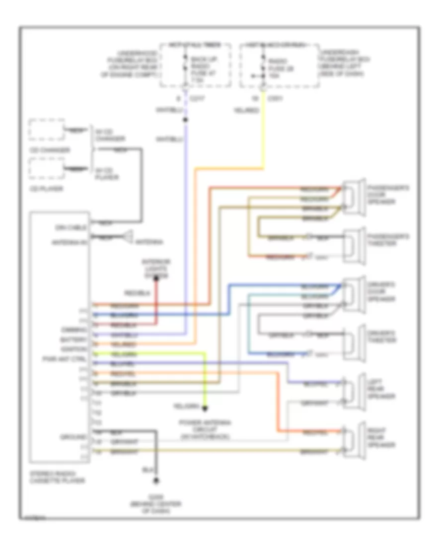
RADIO
Radio Wiring Diagram for Acura Integra GS-R 1999
List of elements for Radio Wiring Diagram for Acura Integra GS-R 1999:
- (+)
- (-)
- Antenna
- Antenna in
- Back up, radio fuse 47 7.5a
- Battery
- C217
- C551
- Cd changer
- Cd player
- Dimming
- Din cable
- Driver's door speaker
- Driver's tweeter
- G206 (behind center of dash)
- Ground
- Hot at all times
- Hot in acc or run
- Ignition
- Interior lights system
- Left rear speaker
- Nca
- Passenger's door speaker
- Passenger's tweeter
- Power antenna circuit (w/ hatchback)
- Pwr ant ctrl
- Radio fuse 28 10a
- Right rear speaker
- Stereo radio/ cassette player
- Underdash fuse/relay box (behind left side of dash)
- Underhood fuse/relay box (on right rear of engine compt)
- W/ cd changer
- W/ cd player
SHIFT INTERLOCK
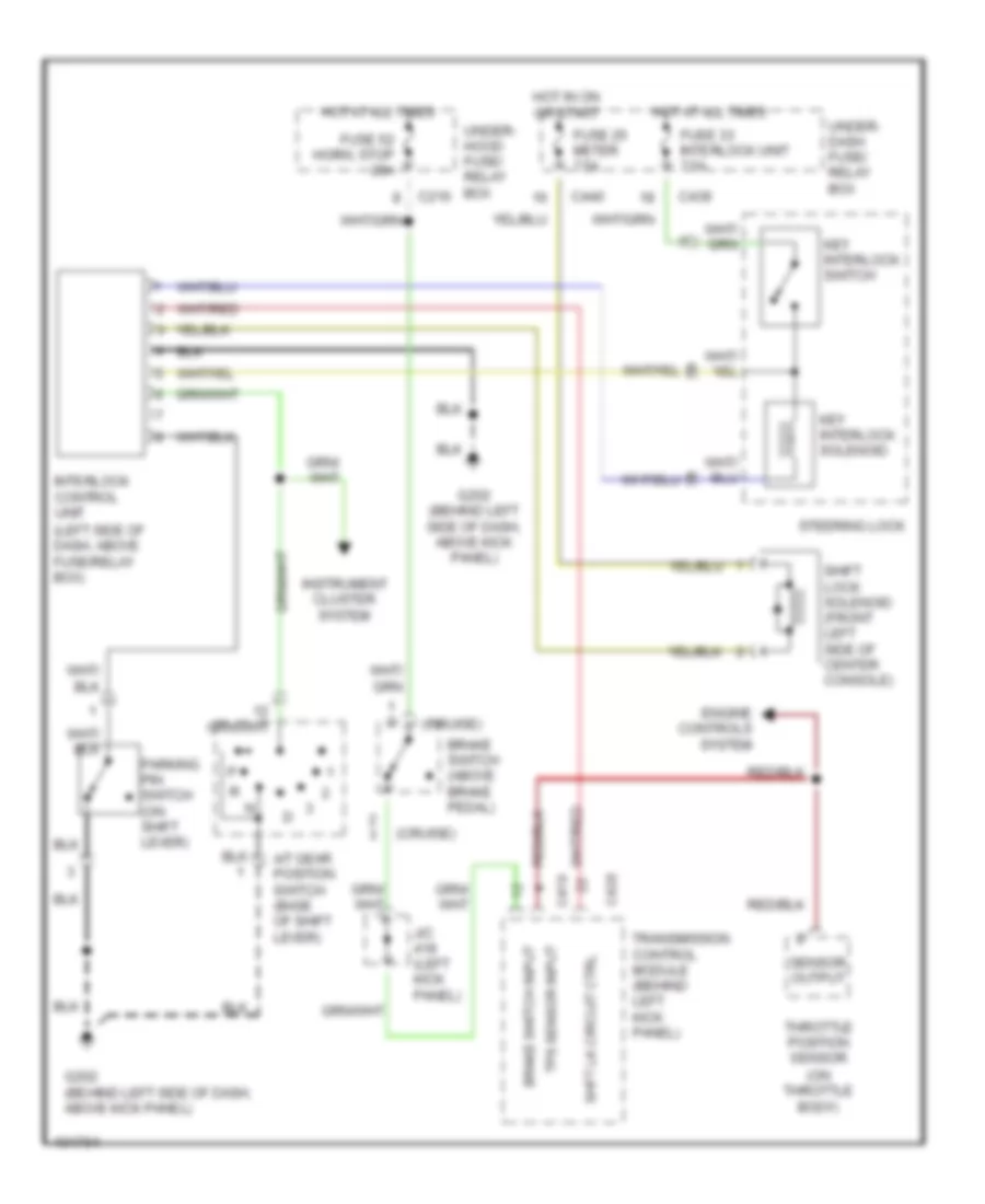
Shift Interlock Wiring Diagram for Acura Integra GS-R 1999
List of elements for Shift Interlock Wiring Diagram for Acura Integra GS-R 1999:
- (cruise)
- (left side of dash, above fuse/relay box)
- (on throttle body)
- A/t gear position switch (base of shift lever)
- Brake switch (above brake pedal)
- Brake switch input
- C216
- C419
- C420
- C439
- C440
- Engine controls system
- Fuse 25 meter 7.5a
- Fuse 33 interlock unit 7.5a
- Fuse 52 horn, stop 20a
- G202 (behind left side of dash, above kick panel)
- Hot at all times
- Hot in on or start
- Instrument cluster system
- Interlock control unit
- J/c (left kick panel)
- Key interlock solenoid
- Key interlock switch
- Parking pin switch (on shift lever)
- Sensor output
- Shft lk circuit ctrl
- Shift lock solenoid (front left side of center console)
- Steering lock
- Throttle position sensor
- Tps sensor input
- Transmission control module (behind left kick panel)
- Under- dash fuse/ relay box
- Under- hood fuse/ relay box
STARTING/CHARGING
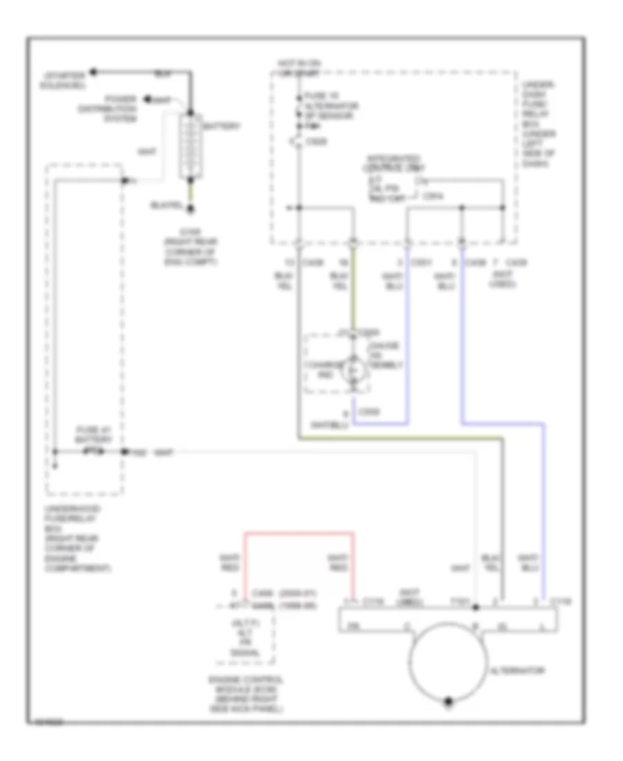
Charging Wiring Diagram, Canada for Acura Integra GS-R 1999
List of elements for Charging Wiring Diagram, Canada for Acura Integra GS-R 1999:
- (1998-99)
- (2000-01)
- (alt f) alt. fr signal
- (not used)
- (starter solenoid)
- Alternator
- Battery
- C119
- C409
- C438
- C439
- C551
- C559
- C560
- C914
- C928
- Charge ind.
- Engine control module (ecm) (behind right side kick panel)
- Fuse 15 alternator sp sensor 7.5a
- Fuse 41 battery 100a
- G105 (right rear corner of eng compt)
- Gauge as- sembly
- Hot in on or start
- Integrated control unit
- Lo oil psi ind. ckt.
- Power distribution system
- T101
- T102
- Under- dash fuse/ relay box (under left side of dash)
- Underhood fuse/relay box (right rear corner of engine compartment)
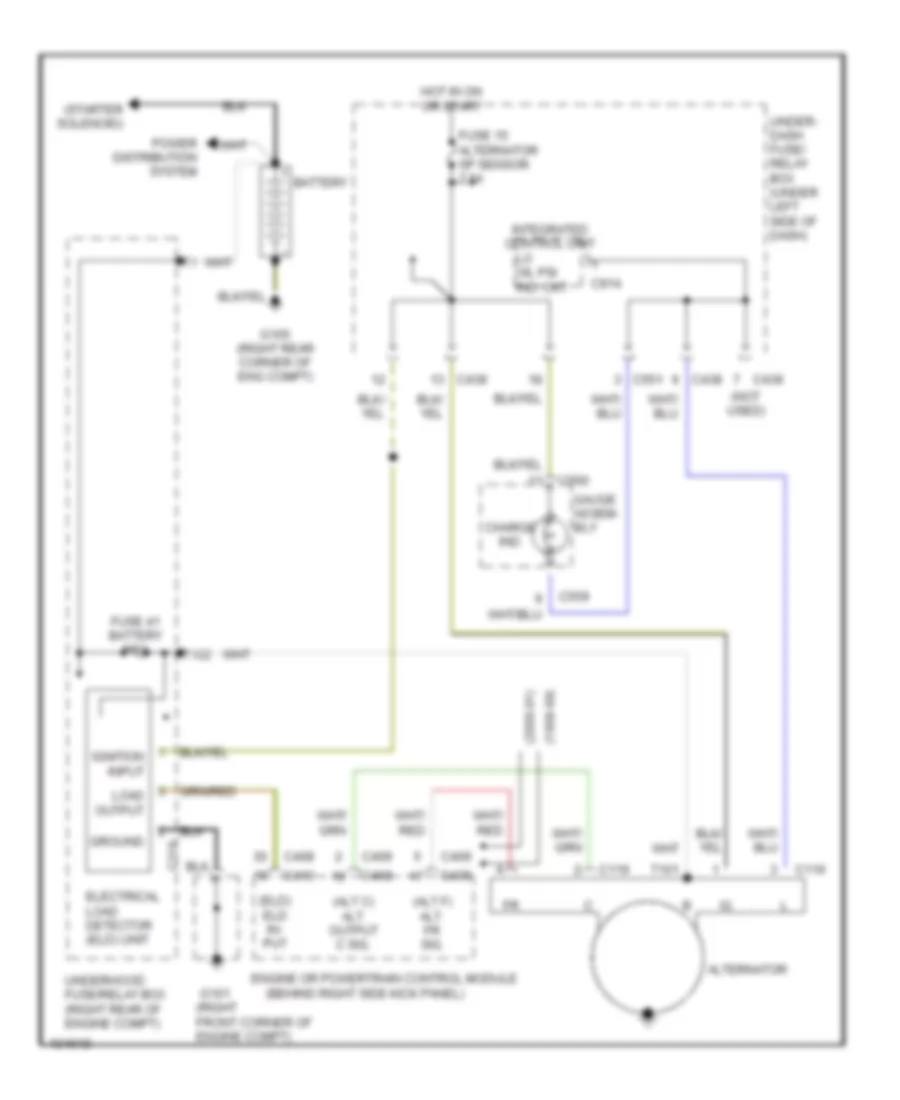
Charging Wiring Diagram, USA for Acura Integra GS-R 1999
List of elements for Charging Wiring Diagram, USA for Acura Integra GS-R 1999:
- (1998-99)
- (2000-01)
- (alt c) alt. output c sig.
- (alt f) alt. fr sig.
- (behind right side kick panel)
- (eld) eld in- put
- (not used)
- (right front corner of engine compt)
- (starter solenoid)
- Alternator
- Battery
- C119
- C218
- C408
- C409
- C410
- C438
- C439
- C551
- C559
- C560
- C914
- Charge ind.
- Electrical load detector (eld) unit
- Engine or powertrain control module
- Fuse 15 alternator sp sensor 7.5a
- Fuse 41 battery 100a
- G101
- G105 (right rear corner of eng compt)
- Gauge assem- bly
- Ground
- Hot in on or start
- Ignition input
- Integrated control unit
- Lo oil psi ind. ckt.
- Load output
- Power distribution system
- T101
- T102
- Under- dash fuse/ relay box (under left side of dash)
- Underhood fuse/relay box (right rear of engine compt)
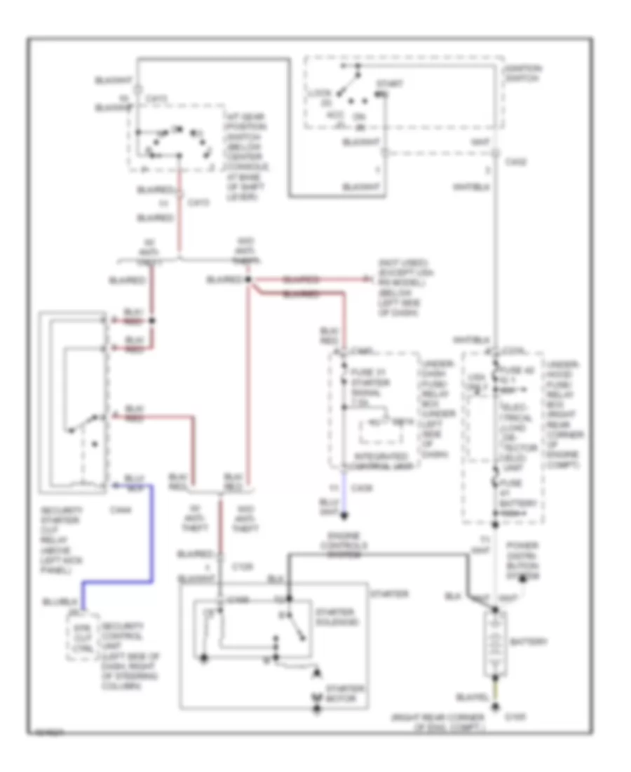
Starting Wiring Diagram, A/T for Acura Integra GS-R 1999
List of elements for Starting Wiring Diagram, A/T for Acura Integra GS-R 1999:
- (not used) (except usa rs model) (below left side of dash)
- (right rear corner of eng. compt.)
- A/t gear position switch (below center console, at base of shift lever)
- Acc (i)
- Battery
- C105
- C126
- C216
- C413
- C432
- C439
- C440
- C444
- C914
- Elec- trical load de- tector (eld) unit
- Engine controls system
- Fuse 31 starter signal 7.5a
- Fuse 42 ig 1 40a
- Fuse battery 100a
- G105
- Ignition switch
- Integrated control unit
- Lock (0)
- On (ii)
- Power distri- bution system
- Security control unit (left side of dash, right of steering column)
- Security starter cut relay (above left kick panel)
- Start (iii)
- Starter
- Starter motor
- Starter solenoid
- Str. cut ctrl
- Under- dash fuse/ relay box (under left side of dash)
- Under- hood fuse/ relay box (right rear corner of engine compt)
- Usa only
- W/ anti- theft
- W/o anti- theft
Starting Wiring Diagram, M/T for Acura Integra GS-R 1999
List of elements for Starting Wiring Diagram, M/T for Acura Integra GS-R 1999:
- (above left kick panel)
- (all except usa rs model)
- (not used) (below left side of dash)
- (right rear corner of eng. compt.)
- Acc (i)
- Battery
- C105
- C126
- C216
- C432
- C439
- C440
- C444
- C447
- C914
- Clutch inter- lock switch (above clutch pedal)
- Elec- trical load de- tector (eld) unit
- Engine controls system
- Fuse 31 starter signal 7.5a
- Fuse 42 ig 1 40a
- Fuse battery 100a
- G105
- G200
- Ignition switch
- Integrated control unit
- Lock (0)
- On (ii)
- Power distri- bution system
- Security control unit (left side of dash, right of steering column)
- Security starter cut relay (above left kick panel)
- Start (iii)
- Starter
- Starter cut relay (above left kick panel)
- Starter motor
- Starter solenoid
- Str. cut ctrl
- Under- dash fuse/ relay box (under left side of dash)
- Under- hood fuse/ relay box (right rear corner of engine compt)
- Usa only
- W/ anti- theft
- W/o anti- theft
SUPPLEMENTAL RESTRAINTS
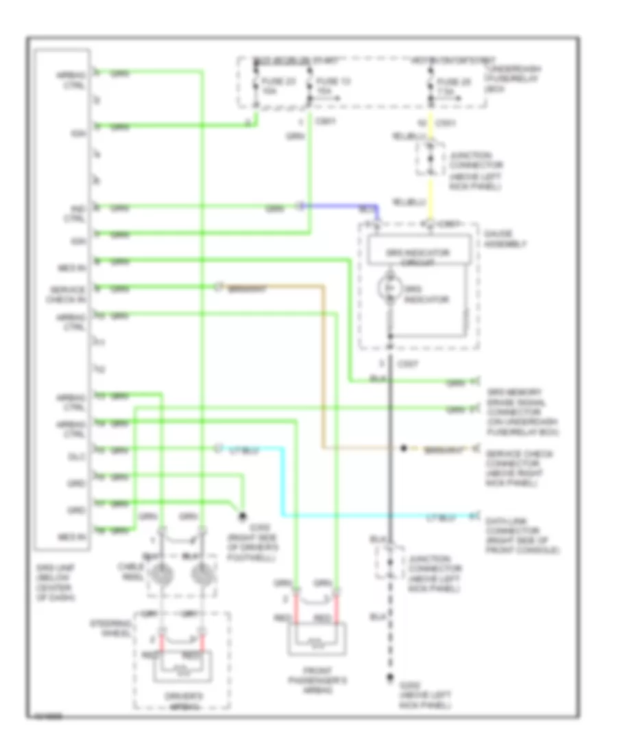
Supplemental Restraints Wiring Diagram for Acura Integra GS-R 1999
List of elements for Supplemental Restraints Wiring Diagram for Acura Integra GS-R 1999:
- (above left kick panel)
- (right side of driver's footwell)
- Airbag ctrl
- C551
- C557
- C801
- Cable reel
- Data link connector (right side of front console)
- Dlc
- Driver's airbag
- Front passenger's airbag
- Fuse 13 15a
- Fuse 23 10a
- Fuse 25 7.5a
- G202 (above left kick panel)
- G302
- Gauge assembly
- Grd
- Hot in on or start
- Ign
- Ind ctrl
- Junction connector
- Junction connector (above left kick panel)
- Mes in
- Red
- Service check connector (above right kick panel)
- Service check in
- Srs indicator
- Srs indicator circuit
- Srs memory erase signal connector (on underdash fuse/relay box)
- Srs unit (below center of dash)
- Steering wheel
- Underdash fuse/relay box
TRANSMISSION
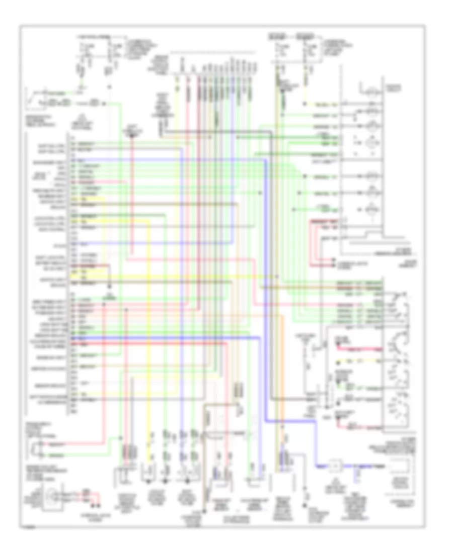
A/T Wiring Diagram for Acura Integra GS-R 1999
List of elements for A/T Wiring Diagram for Acura Integra GS-R 1999:
- (left dash) c556 j/c
- (left kick panel)
- (left side of dash)
- (not used)
- (on left rear of transaxle)
- (on rear cylinder head)
- (right kick panel) service check connector
- +5v reference
- A/c on input
- A/c system
- A/t gear position console light
- A/t gear position indicator
- A/t gear position switch (below center console, at base of shift lever)
- A10
- A11
- A12
- A13
- A14
- A15
- A16
- A17
- A18
- A19
- A20
- A21
- A22
- A23
- A24
- A25
- A26
- Afs a
- Afs b
- Anti-theft system
- At chk
- Atp d3
- Atp d4
- Atp pn
- Atp1
- Atp2
- B10
- B11
- B12
- B13
- B14
- B15
- B16
- B17
- B18
- B19
- B20
- B21
- B22
- B6 up/dn shift sig
- B7 up/dn shift sig
- Bar out
- Baro press input
- Battery backup
- Brake sw input
- Brake switch (on brake pedal support)
- C10
- C108
- C128
- C19
- C21
- C216
- C217
- C27
- C28
- C29
- C438
- C551
- Countershaft spd
- Countershaft speed sensor
- Cruise control
- D10
- D11
- Dimming circuit
- Distributor assembly
- Drive inputs
- Ect
- Ect sensor input
- Engine control module (right kick panel)
- Engine coolant temperature sensor
- Engine spd input
- Exterior lights system
- Fuse 10a
- Fuse 20a
- Fuse 7.5a
- G120 (on engine coolant outlet)
- G200
- Gauge assembly
- Ground
- Hot at all times
- Hot in on or start
- Ignition control module
- Ignition input
- Indic control
- Interior lights system
- J/c c418 (above left kick panel)
- Lock-up control solenoid valves
- Lockup sol ctrl
- Mainshaft speed
- Mainshaft speed sensor
- Nca
- Park/neutr input
- Pnk
- Red
- Reverse input
- Scs
- Sensor ground
- Service chk conn
- Sg2
- Shift ac
- Shift acknowledge
- Shift control solenoid valves
- Shift interlock system
- Shift lock ctrl
- Shift sol ctrl
- Test tachometer connector (left rear corner of engine compartment)
- Throttle position sensor (on throttle body)
- Tp sensor input
- Tps
- Transmission control module (left kick panel)
- Underdash fuse/relay box
- Underhood fuse/relay box (right rear of engine compt)
- Vcc 2
- Vehicle speed sensor (top left front of transaxle)
- Vref
- Vss input
TRUNK, TAILGATE, FUEL DOOR
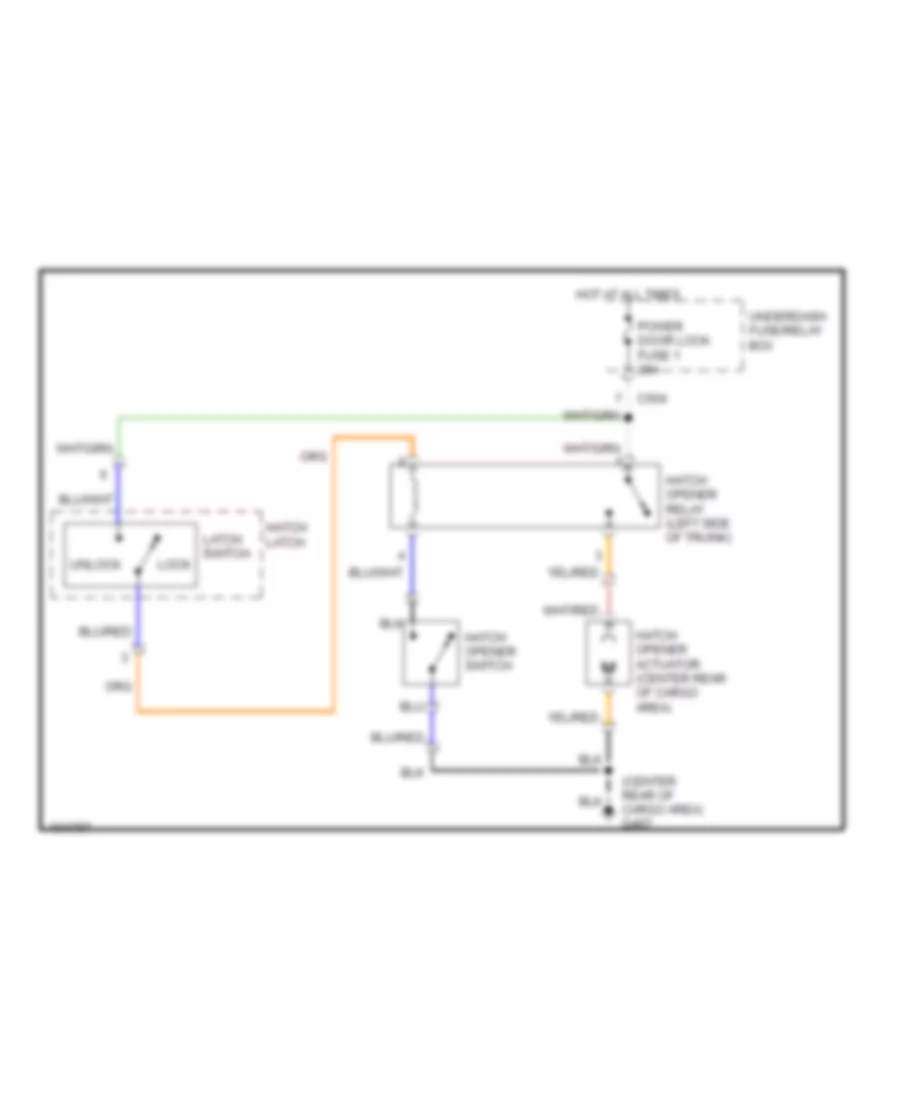
Trunk, Tailgate, Fuel Door Wiring Diagram, Hatchback for Acura Integra GS-R 1999
List of elements for Trunk, Tailgate, Fuel Door Wiring Diagram, Hatchback for Acura Integra GS-R 1999:
- (center rear of cargo area) g407
- C504
- Hatch latch
- Hatch opener actuator (center rear of cargo area)
- Hatch opener relay (left side of trunk)
- Hatch opener switch
- Hot at all times
- Latch switch
- Lock
- Power door lock fuse 1 20a
- Underdash fuse/relay box
- Unlock
WARNING SYSTEMS
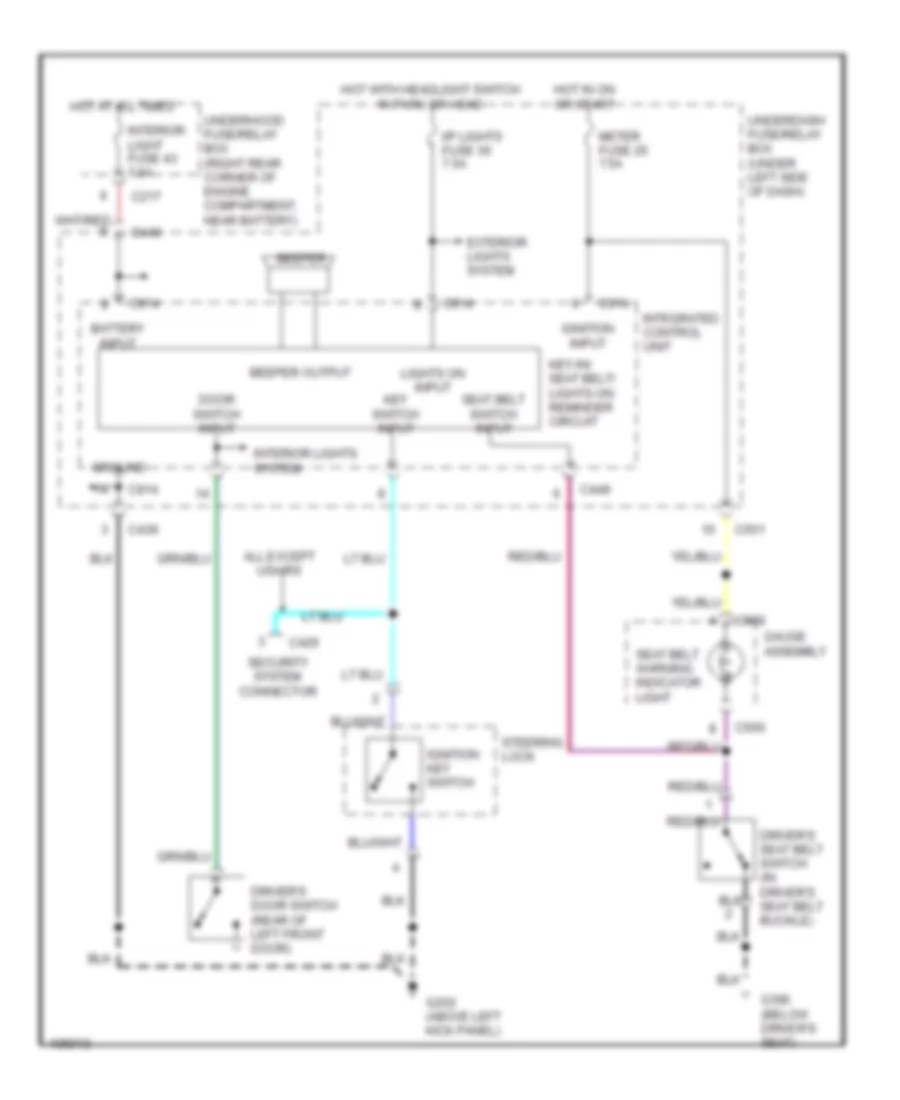
Warning Systems Wiring Diagram for Acura Integra GS-R 1999
List of elements for Warning Systems Wiring Diagram for Acura Integra GS-R 1999:
- All except usa rs
- Battery input
- Beeper
- Beeper output
- C217
- C426
- C439
- C440
- C449
- C551
- C559
- C560
- C914
- Door switch input
- Driver's door switch (rear of left front door)
- Driver's seat belt switch (in driver's seat belt buckle)
- Exterior lights system
- G202 (above left kick panel)
- G300 (below driver's seat)
- Gauge assembly
- Ground
- Hot at all times
- Hot in on or start
- Hot with headlight switch in park or head
- I/p lights fuse 30 7.5a
- Ignition input
- Ignition key switch
- Integrated control unit
- Interior light fuse 43 7.5a
- Interior lights system
- Key switch input
- Key-in/ seat belt/ lights-on reminder circuit
- Lights on input
- Meter fuse 25 7.5a
- Seat belt switch input
- Seat belt warning indicator light
- Security system connector
- Steering lock
- Underdash fuse/relay box (under left side of dash)
- Underhood fuse/relay box (right rear corner of engine compartment, near battery)
WIPER/WASHER
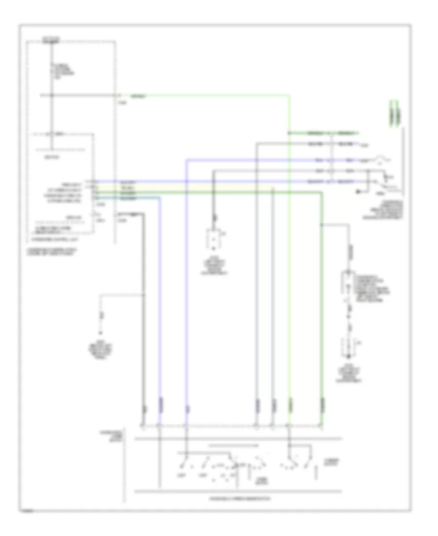
Front Wiper/Washer Wiring Diagram for Acura Integra GS-R 1999
List of elements for Front Wiper/Washer Wiring Diagram for Acura Integra GS-R 1999:
- C439
- C442
- C449
- C914
- Combination wiper switch
- Fuse 26 fr wiper fr washer 20a
- G100 (left front corner of engine compartment)
- G202 (behind left side of dash, above kick panel)
- Ground
- High
- Hot in on or start
- Ignition
- Int
- Int wiper on input
- Int/park wipe ctrl
- Integrated control unit
- Intermittent wiper relay circuit
- J/c
- Low
- Mist
- Off
- Park
- Park input
- Run
- Underdash fuse/relay box (under left side of dash)
- Washer switch
- Windshield wash on
- Windshield washer motor (on bottom front of washer reservoir, behind left side of front bumper)
- Windshield wiper motor (behind air scoop at left rear of engine compartment)
- Windshield wiper/washer switch
- Wiper switch
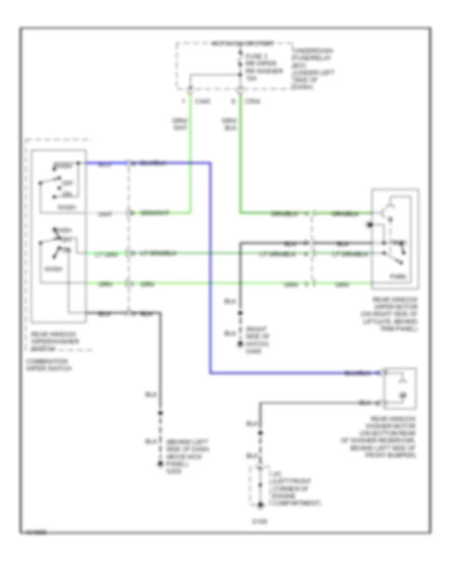
Rear Wiper/Washer Wiring Diagram for Acura Integra GS-R 1999
List of elements for Rear Wiper/Washer Wiring Diagram for Acura Integra GS-R 1999:
- (behind left side of dash, above kick panel) g202
- (right side of hatch) g406
- C442
- C504
- Combination wiper switch
- Fuse 3 rr wiper rr washer 10a
- G100
- Hot in on or start
- J/c (left front corner of engine compartment)
- Off
- Park
- Rear window washer motor (on bottom rear of washer reservoir, behind left side of front bumper)
- Rear window wiper motor (on right side of liftgate, behind trim panel)
- Rear window wiper/washer switch
- Run
- Underdash fuse/relay box (under left side of dash)
- Wash

 Čeština
 Dansk
Dansk Deutsch
 Ελληνικά
 English
 English
 Español
 Suomi
Suomi Français
 Français
 עברית
עברית Magyar
 Italiano
 日本語
日本語 한국어
한국어 Nederlands
 Polski
 Português
 Português
 Română
 Русский
 Slovenčina
 Slovenščina
 Svenska
 Türkçe
 中文 (中国)