AIR CONDITIONING
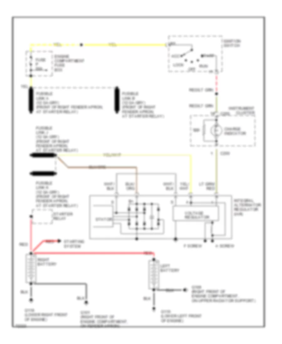
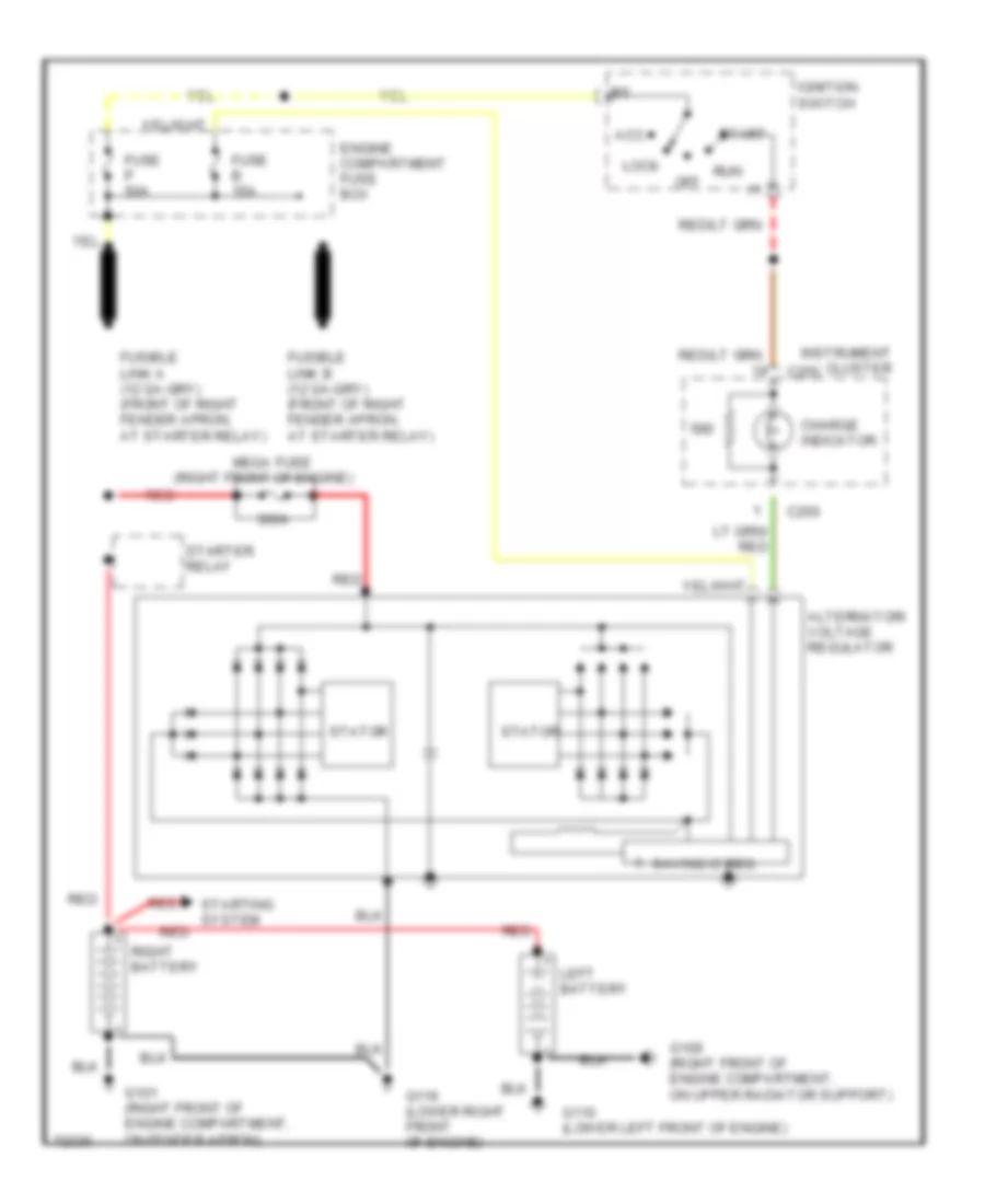
4.9L
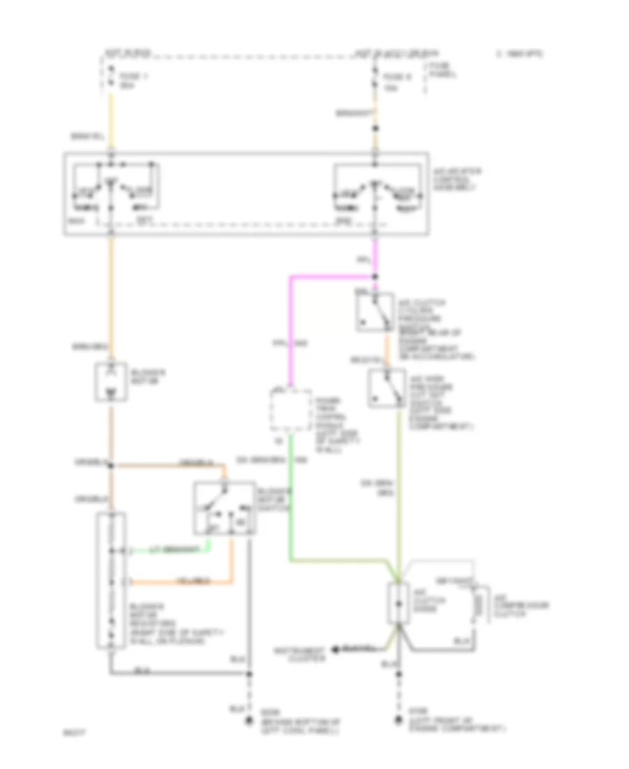
4.9L, A/C Wiring Diagram, California for Ford Cab & Chassis F350 1995
 https://portal-diagnostov.com/license.html
Automotive Electricians Portal FZCO
Automotive Electricians Portal FZCO
https://portal-diagnostov.com/license.html
https://portal-diagnostov.com/license.html
Automotive Electricians Portal FZCO
Automotive Electricians Portal FZCO
List of elements for 4.9L, A/C Wiring Diagram, California for Ford Cab & Chassis F350 1995:
- (not used)
- 15a
- A/c clutch cycling pressure switch (right rear of engine compartment on accumulator)
- A/c clutch diode
- A/c compressor clutch
- A/c high pressure cut out switch (left side engine compartment)
- A/c-heater control assembly
- Blower motor
- Blower motor resistors (right side of safety wall, on plenum)
- Blower motor switch
- C 1995 vftc
- Def
- Floor
- Fuse 1 30a
- Fuse 6
- Fuse panel
- G108
- G200 (behind bottom of left cowl panel)
- Hot in accy or run
- Hot in run
- Max
- Mix
- Norm
- Off
- Oxygen sensors
- Pcm power relay
- Power- train control module (left side of safety wall)
- Red
- Vent
- Wac relay (engine compartment fuse box)
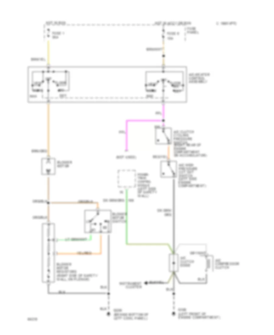
4.9L, A/C Wiring Diagram, Federal for Ford Cab & Chassis F350 1995
List of elements for 4.9L, A/C Wiring Diagram, Federal for Ford Cab & Chassis F350 1995:
- (left front of engine compartment)
- 15a
- A/c clutch cycling pressure switch (right rear of engine compartment on accumulator)
- A/c clutch diode
- A/c compressor clutch
- A/c high pressure cut out switch (left side engine compartment)
- A/c-heater control assembly
- Blower motor
- Blower motor resistors (right side of safety wall, on plenum)
- Blower motor switch
- C 1995 vftc
- Def
- Floor
- Fuse 1 30a
- Fuse 6
- Fuse panel
- G108
- G200 (behind bottom of left cowl panel)
- Hot in accy or run
- Hot in run
- Instrument cluster
- Max
- Mix
- Norm
- Off
- Power- train control module (left side of safety wall)
- Vent
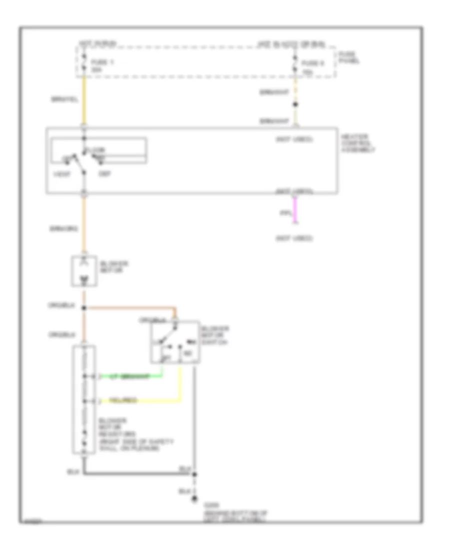
Heater Wiring Diagram for Ford Cab & Chassis F350 1995
List of elements for Heater Wiring Diagram for Ford Cab & Chassis F350 1995:
- (not used)
- 15a
- Blower motor
- Blower motor resistors (right side of safety wall, on plenum)
- Blower motor switch
- Def
- Floor
- Fuse 1 30a
- Fuse 6
- Fuse panel
- G200 (behind bottom of left cowl panel)
- Heater control assembly
- Hot in accy or run
- Hot in run
- Mix
- Off
- Vent
5.0L
5.0L, A/C Wiring Diagram for Ford Cab & Chassis F350 1995
List of elements for 5.0L, A/C Wiring Diagram for Ford Cab & Chassis F350 1995:
- (left front of engine compartment)
- (not used)
- 15a
- A/c clutch cycling pressure switch (right rear of engine compartment on accumulator)
- A/c clutch diode
- A/c compressor clutch
- A/c high pressure cut out switch (left side engine compartment)
- A/c-heater control assembly
- Blower motor
- Blower motor resistors (right side of safety wall, on plenum)
- Blower motor switch
- C 1995 vftc
- Def
- Floor
- Fuse 1 30a
- Fuse 6
- Fuse panel
- G108
- G200 (behind bottom of left cowl panel)
- Hot in accy or run
- Hot in run
- Instrument cluster
- Max
- Mix
- Norm
- Off
- Power- train control module (left side of safety wall)
- Vent
Heater Wiring Diagram for Ford Cab & Chassis F350 1995
List of elements for Heater Wiring Diagram for Ford Cab & Chassis F350 1995:
- (not used)
- 15a
- Blower motor
- Blower motor resistors (right side of safety wall, on plenum)
- Blower motor switch
- Def
- Floor
- Fuse 1 30a
- Fuse 6
- Fuse panel
- G200 (behind bottom of left cowl panel)
- Heater control assembly
- Hot in accy or run
- Hot in run
- Mix
- Off
- Vent
5.8L
5.8L, A/C Wiring Diagram for Ford Cab & Chassis F350 1995
List of elements for 5.8L, A/C Wiring Diagram for Ford Cab & Chassis F350 1995:
- (left front of engine compartment)
- (not used)
- 15a
- A/c clutch cycling pressure switch (right rear of engine compartment on accumulator)
- A/c clutch diode
- A/c compressor clutch
- A/c high pressure cut out switch (left side engine compartment)
- A/c-heater control assembly
- Blower motor
- Blower motor resistors (right side of safety wall, on plenum)
- Blower motor switch
- C 1995 vftc
- Def
- Floor
- Fuse 1 30a
- Fuse 6
- Fuse panel
- G108
- G200 (behind bottom of left cowl panel)
- Hot in accy or run
- Hot in run
- Instrument cluster
- Max
- Mix
- Norm
- Off
- Power- train control module (left side of safety wall)
- Vent
Heater Wiring Diagram for Ford Cab & Chassis F350 1995
List of elements for Heater Wiring Diagram for Ford Cab & Chassis F350 1995:
- (not used)
- 15a
- Blower motor
- Blower motor resistors (right side of safety wall, on plenum)
- Blower motor switch
- Def
- Floor
- Fuse 1 30a
- Fuse 6
- Fuse panel
- G200 (behind bottom of left cowl panel)
- Heater control assembly
- Hot in accy or run
- Hot in run
- Mix
- Off
- Vent
7.3L
7.3L Diesel, Air Conditioning Wiring Diagrams for Ford Cab & Chassis F350 1995
List of elements for 7.3L Diesel, Air Conditioning Wiring Diagrams for Ford Cab & Chassis F350 1995:
- (behind bottom of left cowl panel)
- (not used)
- (right front fender apron)
- 15a
- A/c clutch cycling pressure switch (right rear of engine compartment on accumulator)
- A/c clutch diode
- A/c compressor clutch
- A/c high pressure cut out switch (left side engine compartment)
- A/c-heater control assembly
- Blower motor
- Blower motor resistors (right side of safety wall, on plenum)
- Blower motor switch
- Def
- Floor
- Fuse 1 30a
- Fuse 6
- Fuse panel
- G101
- G200
- Hot in accy or run
- Hot in run
- Max
- Mix
- Norm
- Off
- Power- train control module (left side of safety wall)
- Vent
Heater Wiring Diagram for Ford Cab & Chassis F350 1995
List of elements for Heater Wiring Diagram for Ford Cab & Chassis F350 1995:
- (not used)
- 15a
- Blower motor
- Blower motor resistors (right side of safety wall, on plenum)
- Blower motor switch
- Def
- Floor
- Fuse 1 30a
- Fuse 6
- Fuse panel
- G200 (behind bottom of left cowl panel)
- Heater control assembly
- Hot in accy or run
- Hot in run
- Mix
- Off
- Vent
7.5L
7.5L, A/C Wiring Diagram for Ford Cab & Chassis F350 1995
List of elements for 7.5L, A/C Wiring Diagram for Ford Cab & Chassis F350 1995:
- (left front of engine compartment)
- (not used)
- 15a
- A/c clutch cycling pressure switch (right rear of engine compartment on accumulator)
- A/c clutch diode
- A/c compressor clutch
- A/c high pressure cut out switch (left side engine compartment)
- A/c-heater control assembly
- Blower motor
- Blower motor resistors (right side of safety wall, on plenum)
- Blower motor switch
- C 1995 vftc
- Def
- Floor
- Fuse 1 30a
- Fuse 6
- Fuse panel
- G108
- G200 (behind bottom of left cowl panel)
- Hot in accy or run
- Hot in run
- Instrument cluster
- Max
- Mix
- Norm
- Off
- Power- train control module (left side of safety wall)
- Vent
Heater Wiring Diagram for Ford Cab & Chassis F350 1995
List of elements for Heater Wiring Diagram for Ford Cab & Chassis F350 1995:
- (not used)
- 15a
- Blower motor
- Blower motor resistors (right side of safety wall, on plenum)
- Blower motor switch
- Def
- Floor
- Fuse 1 30a
- Fuse 6
- Fuse panel
- G200 (behind bottom of left cowl panel)
- Heater control assembly
- Hot in accy or run
- Hot in run
- Mix
- Off
- Vent
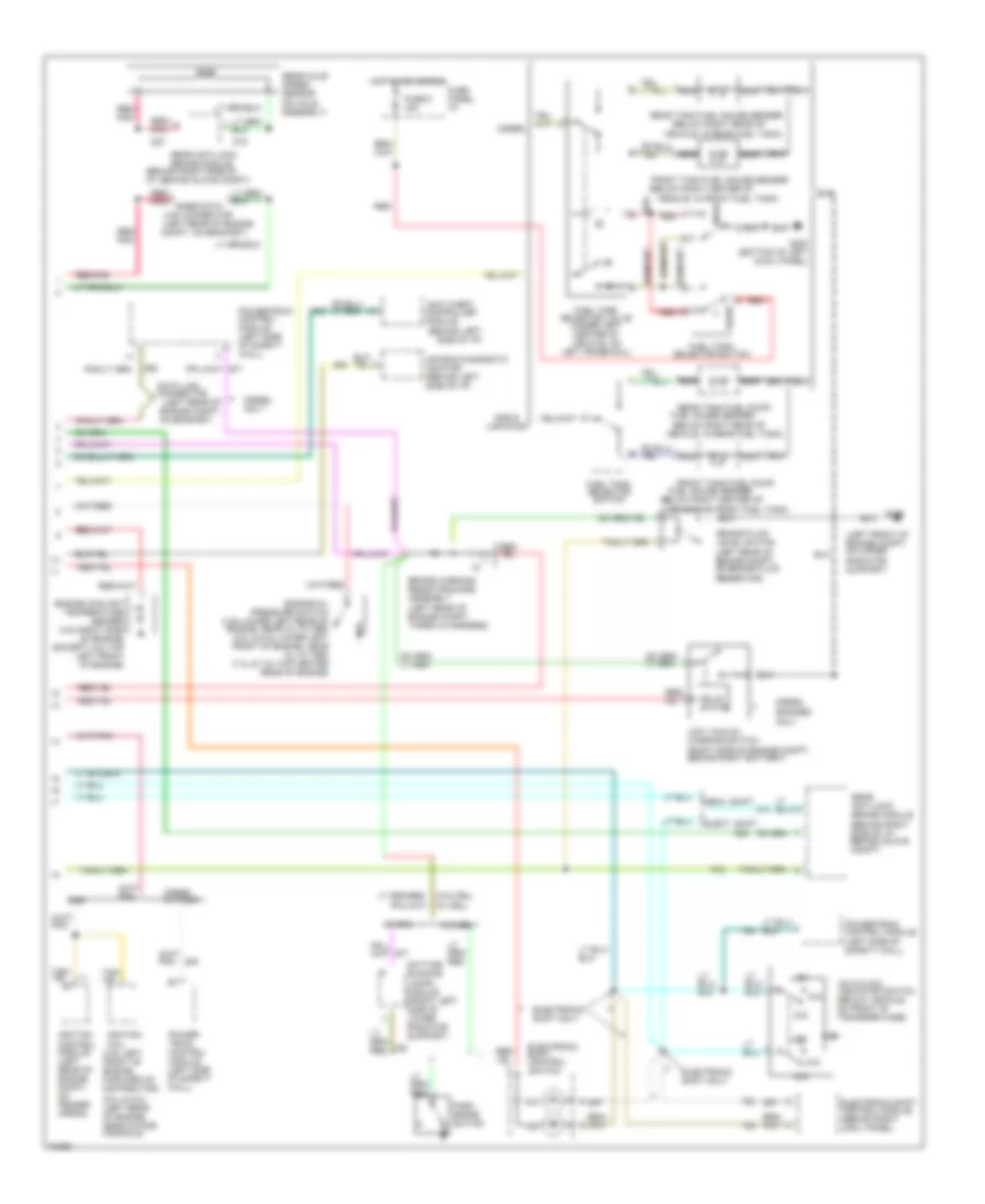
ANTI-LOCK BRAKES
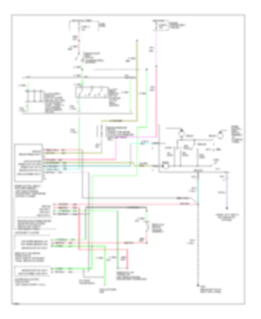
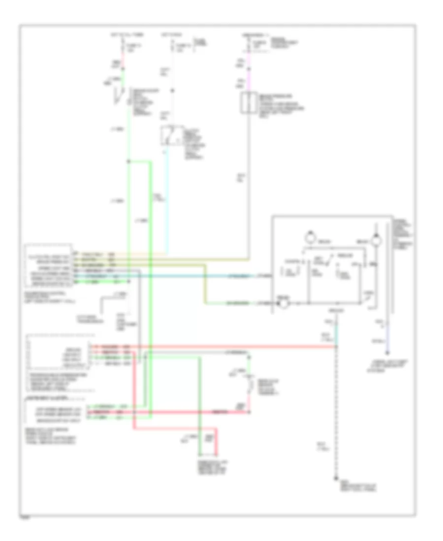
Anti-lock Brake Wiring Diagrams for Ford Cab & Chassis F350 1995
List of elements for Anti-lock Brake Wiring Diagrams for Ford Cab & Chassis F350 1995:
- 4x4 input sig
- Acc
- Anti-lock brake ind
- Boo sw input
- Brake fluid level switch (on brake fluid reservoir)
- Brake fluid lvl sens (lo)
- Brake on/off (boo) switch (top left side of brake/clutch pedal support)
- Diag test/keep alive input
- Diff spd sens (hi)
- Diff spd sens (lo)
- Dump sol output
- Dump solenoid
- Fuse 13 15a
- Fuse 15 20a
- Fuse 17 10a
- Fuse panel
- G101 (right front of engine compartment, front of fender apron)
- G108 (left front of engine compartment, on upper radiator support)
- G200 (behind bottom of left cowl panel)
- G203 (behind bottom of right cowl panel)
- Ground
- Hot at all times
- Hot in run
- Hot in start or run
- Ignition switch
- Instrument cluster
- Instrument cluster system
- Iso sol output
- Isolation solenoid
- Lock
- Nca
- Off
- Power input
- Programmable speedometer/ odometer module
- Rabs data link connector (left rear of engine compartment) (ex 7.3l) (behind lower center of i/p) (7.3l)
- Rabs valve assembly (on frame rail, near front of transmission)
- Rear anti-lock brake (rabs) module (behind right side of i/p, behind glove compartment)
- Rear axle sensor
- Red/pnk
- Run
- Start
- Valve reset switch
- Vlv reset input
- Warn lp output
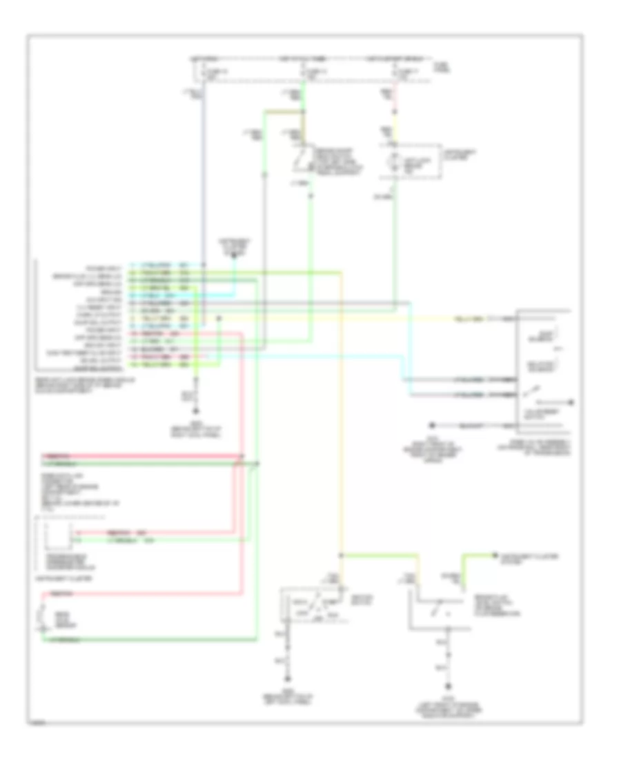
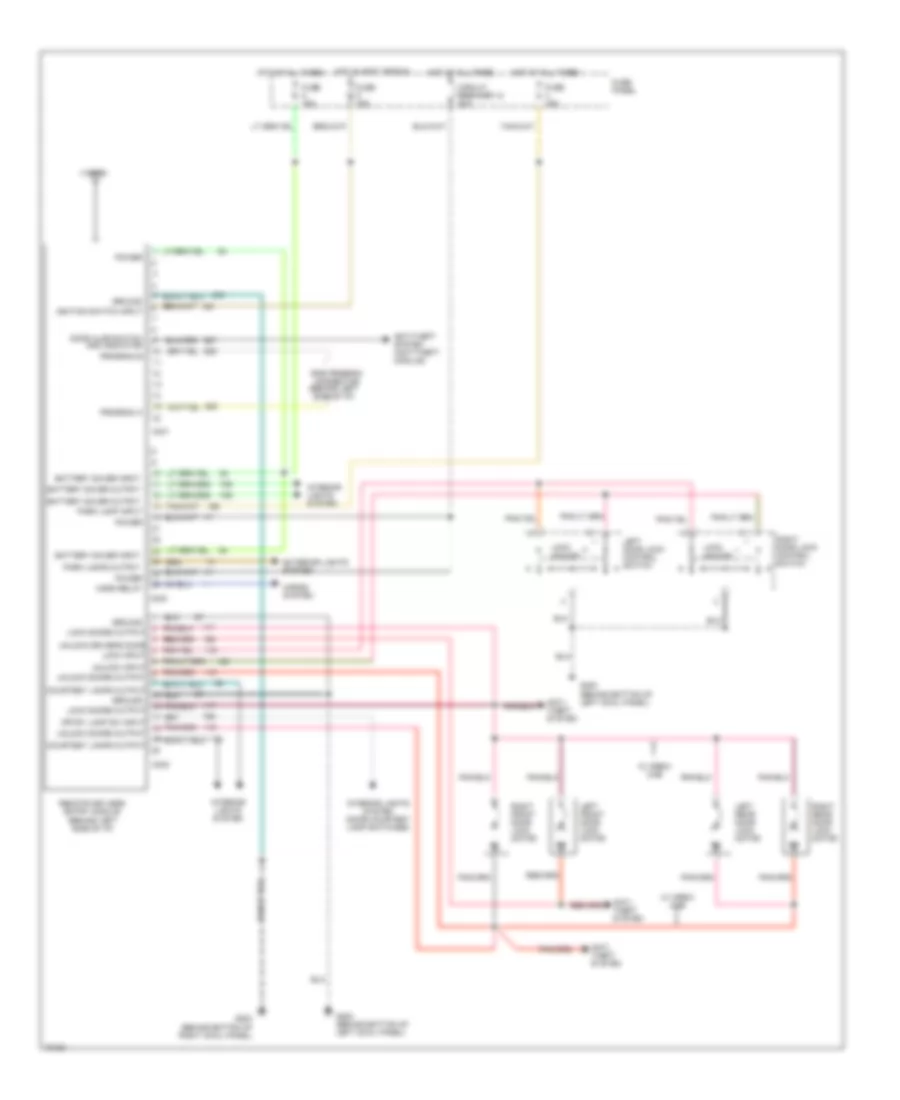
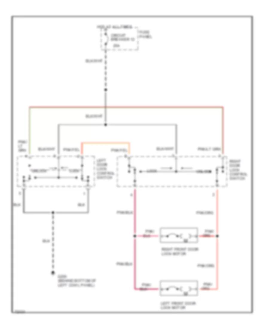
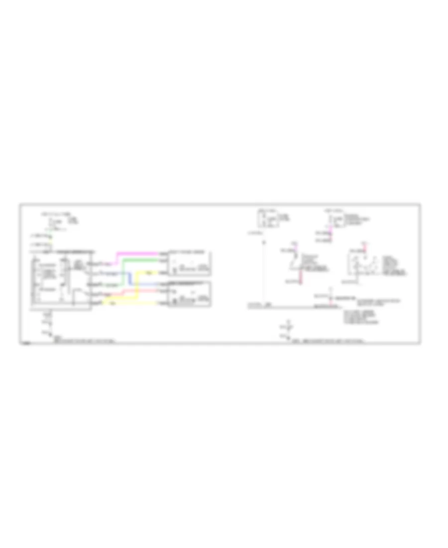
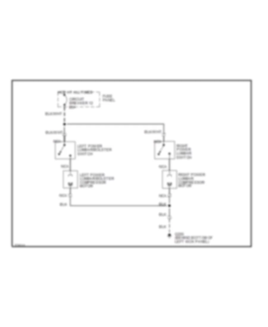
ANTI-THEFT
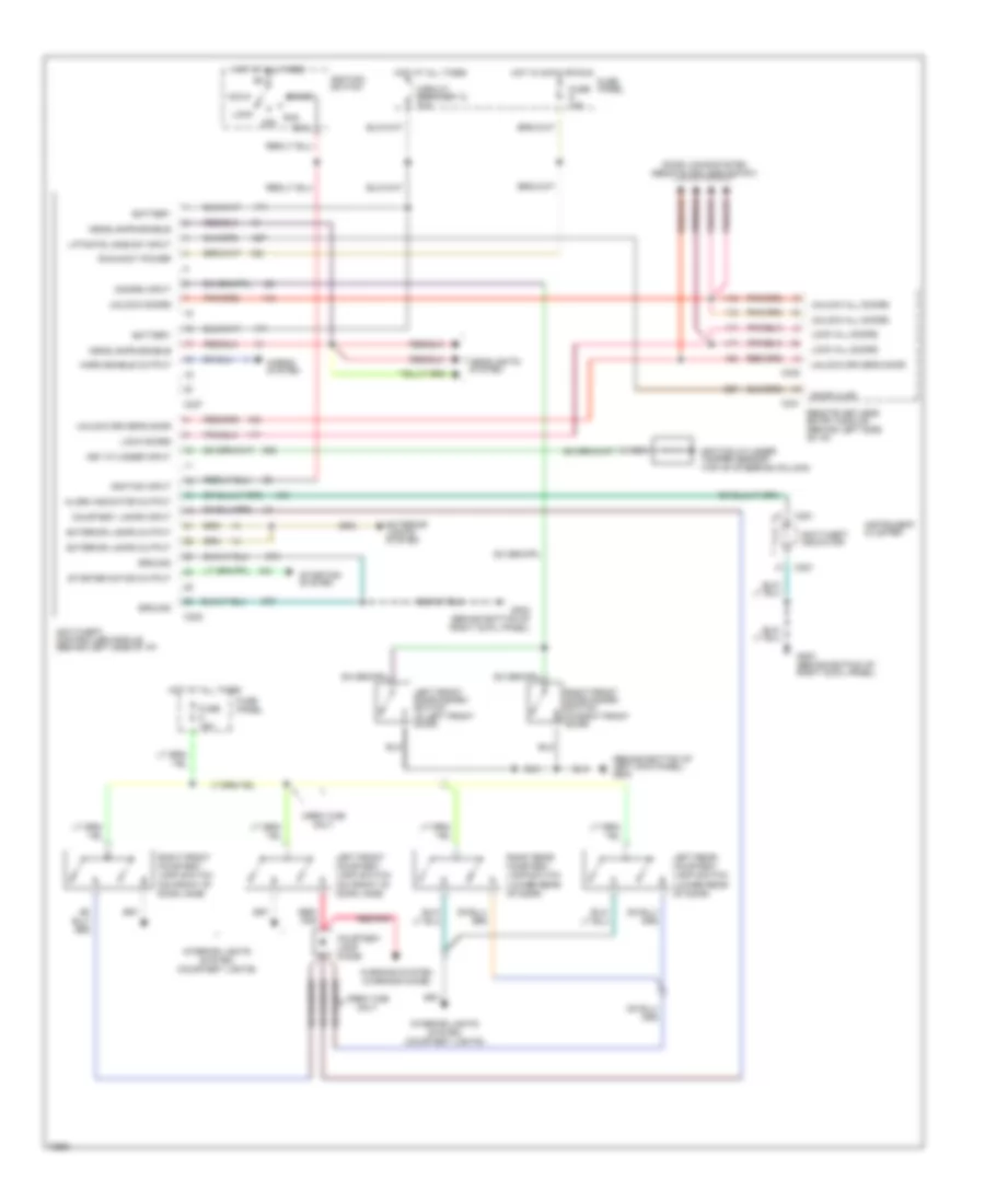
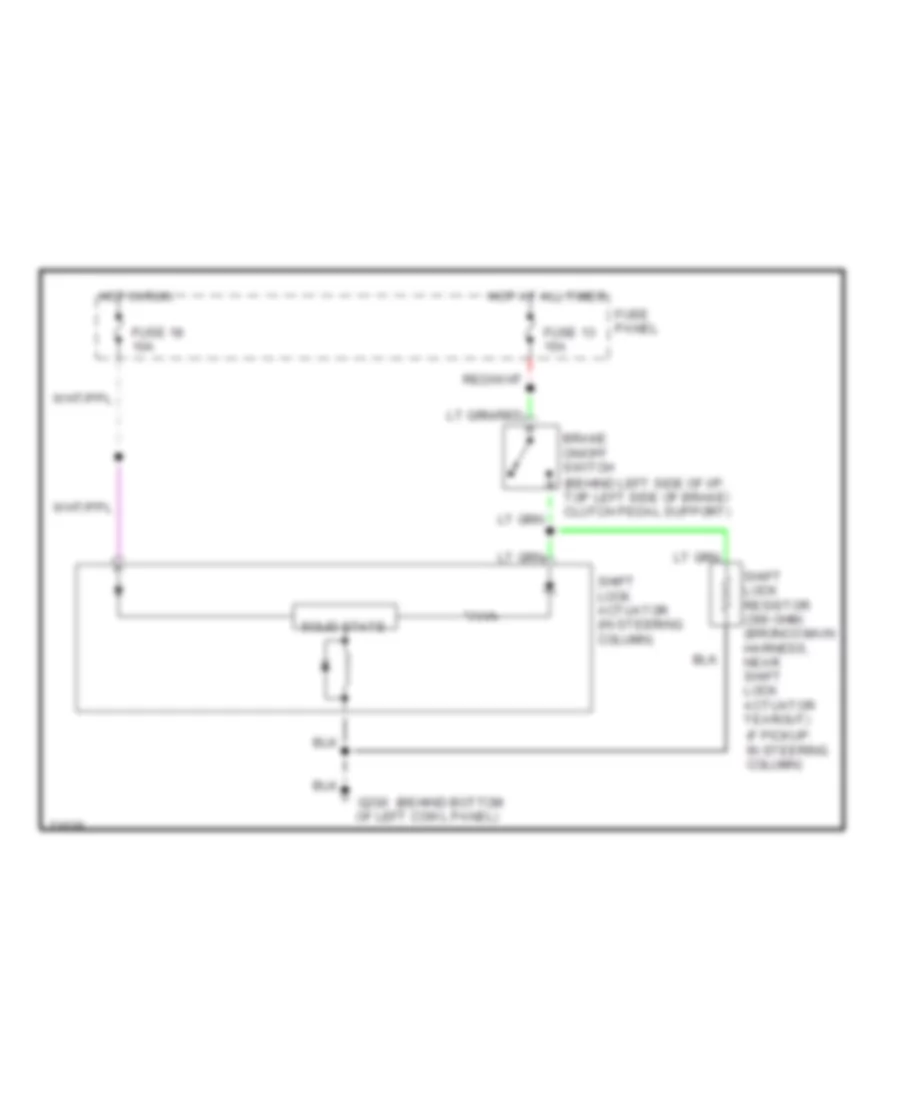
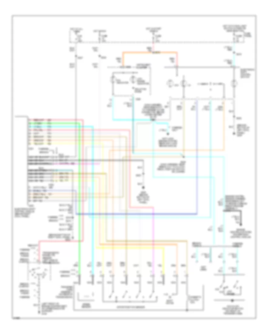
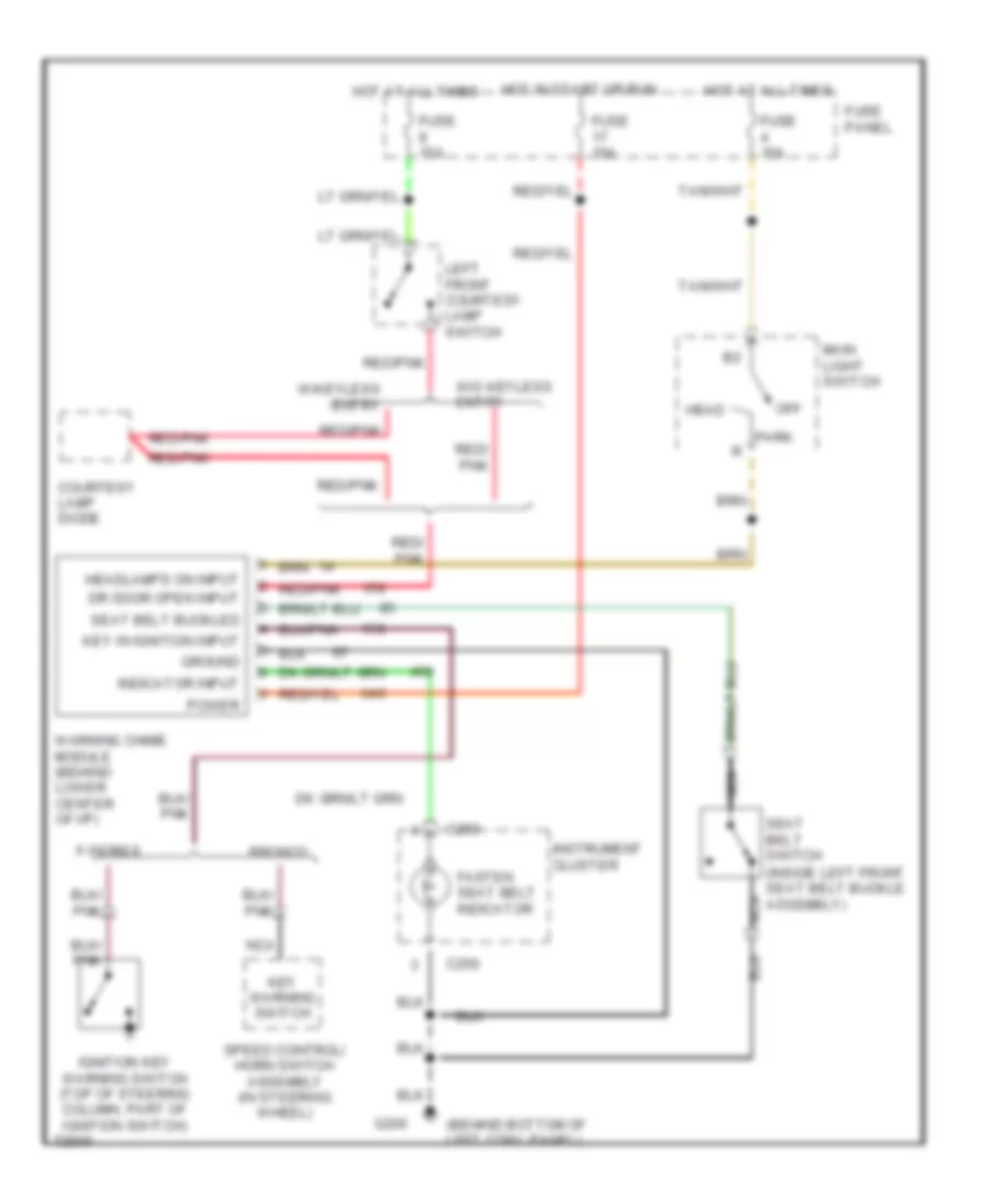
Anti-theft Wiring Diagram for Ford Cab & Chassis F350 1995
List of elements for Anti-theft Wiring Diagram for Ford Cab & Chassis F350 1995:
- (behind bottom of left kick panel) g200
- Acc
- Alarm indicator output
- Anti-theft controller module (behind left side of i/p)
- Anti-theft indicator
- Battery
- C237
- C238
- C241
- C242
- C251
- Circuit breaker 12 20a
- Courtesy lamp diode
- Courtesy lamps input
- Crew cab only
- Disarm input
- Door ajar
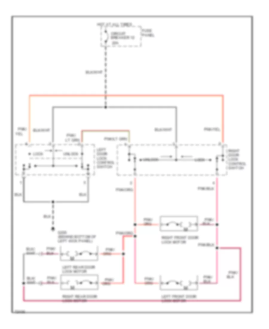
- Door locks system (remote keyless entry)
- Exterior lamps output
- Exterior lights system
- Fuse 15a
- Fuse panel
- G203 (behind bottom of right cowl panel)
- Ground
- Headlamps enable
- Headlights system
- Horn enable output
- Horns system
- Hot at all times
- Hot in accy or run
- Ignition cylinder tamper sensor (top of steering column)
- Ignition input
- Ignition switch
- Instrument cluster
- Interior lights system (courtesy lights)
- Key cylinder input
- Left front courtesy lamp switch (on front of door jamb)
- Left front door disarm switch (in left front door)
- Left rear courtesy lamp switch (lower rear of door)
- Liftgate jamb sw input
- Lock
- Lock all doors
- Lock doors
- Nca
- Off
- Red/ pnk
- Red/pnk
- Remote keyless entry module (behind left side of i/p)
- Right front courtesy lamp switch (on front of door jamb)
- Right front door disarm switch (in right front door)
- Right rear courtesy lamp switch (lower rear of door)
- Run
- Run/accy power
- Sta
- Start
- Starter motor output
- Starting system
- Unlock all doors
- Unlock doors
- Unlock driver's door
- Warning system (warning chime)
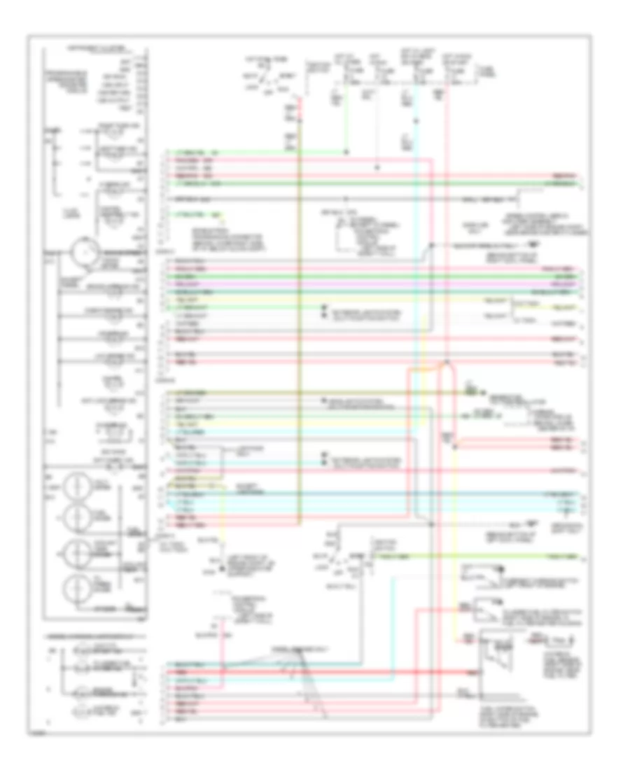
COMPUTER DATA LINES
4.9L
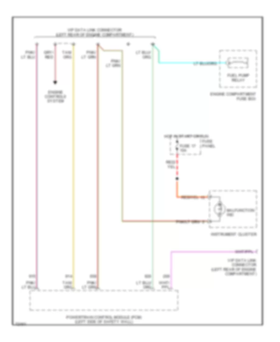
4.9L, Computer Data Lines for Ford Cab & Chassis F350 1995
List of elements for 4.9L, Computer Data Lines for Ford Cab & Chassis F350 1995:
- Engine compartment fuse box
- Engine controls system
- Fuel pump relay
- Fuse 17 10a
- Fuse panel
- Hot in start or run
- Instrument cluster
- Malfunction ind
- Powertrain control module (pcm) (left side of safety wall)
- Vip data link connector (left rear of engine compartment)
5.0L
5.0L, Computer Data Lines for Ford Cab & Chassis F350 1995
List of elements for 5.0L, Computer Data Lines for Ford Cab & Chassis F350 1995:
- Engine compartment fuse box
- Engine controls system
- Fuel pump relay
- Fuse 17 10a
- Fuse panel
- Hot in start or run
- Instrument cluster
- Malfunction ind
- Powertrain control module (pcm) (left side of safety wall)
- Vip data link connector (left rear of engine compartment)
5.8L
5.8L, Computer Data Lines for Ford Cab & Chassis F350 1995
List of elements for 5.8L, Computer Data Lines for Ford Cab & Chassis F350 1995:
- Engine compartment fuse box
- Engine controls system
- Fuel pump relay
- Fuse 17 10a
- Fuse panel
- Hot in start or run
- Instrument cluster
- Malfunction ind
- Powertrain control module (pcm) (left side of safety wall)
- Vip data link connector (left rear of engine compartment)
7.3L
7.3L DI Turbo Diesel, Computer Data Lines for Ford Cab & Chassis F350 1995
List of elements for 7.3L DI Turbo Diesel, Computer Data Lines for Ford Cab & Chassis F350 1995:
- Fuse 16 15a
- Fuse 18 10a
- Fuse panel
- G108 (left front of engine compartment, on upper radiator support)
- G200 (behind bottom of left cowl panel)
- Generic scan tool (behind lower center of i/p)
- Hot at all times
- Hot in run
- Powertrain control module (pcm) (left side of safety wall)
- Selectable rpm control (behind center of i/p)
7.5L
7.5L, Computer Data Lines for Ford Cab & Chassis F350 1995
List of elements for 7.5L, Computer Data Lines for Ford Cab & Chassis F350 1995:
- Engine compartment fuse box
- Engine controls system
- Fuel pump relay
- Fuse 17 10a
- Fuse panel
- Hot in start or run
- Instrument cluster
- Malfunction ind
- Powertrain control module (pcm) (left side of safety wall)
- Vip data link connector (left rear of engine compartment)
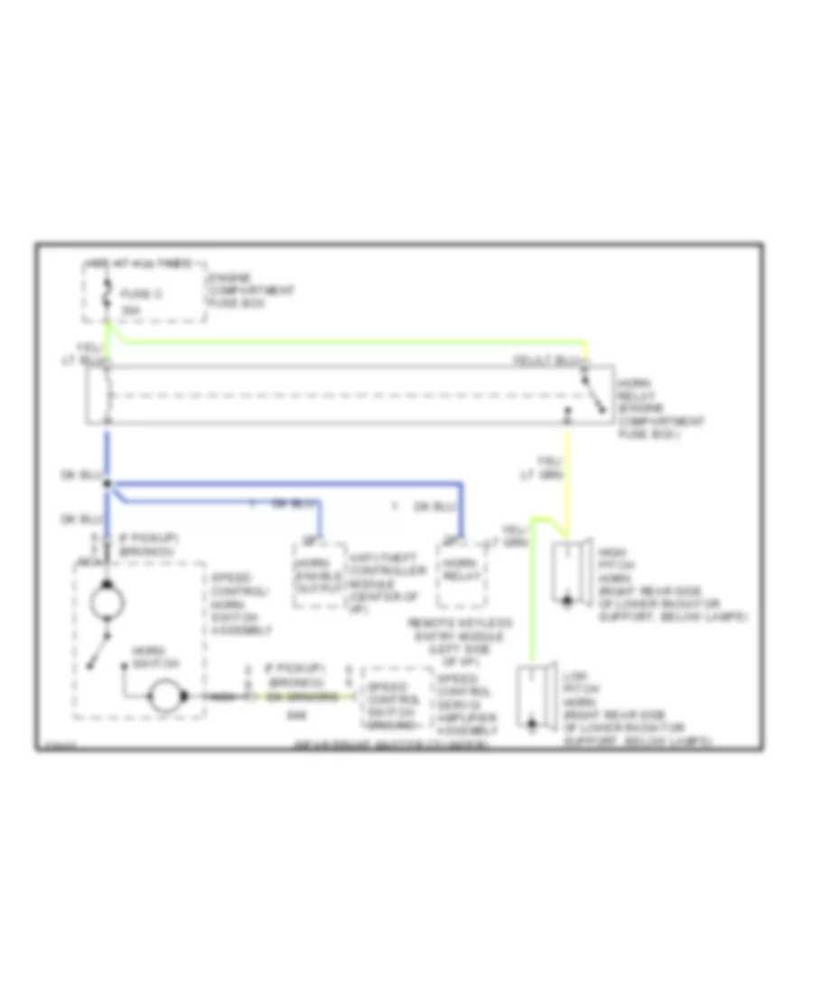
CRUISE CONTROL
4.9L
4.9L, Cruise Control Wiring Diagram for Ford Cab & Chassis F350 1995
List of elements for 4.9L, Cruise Control Wiring Diagram for Ford Cab & Chassis F350 1995:
- (behind bottom of right cowl panel)
- (behind left side of instrument panel, taped to main harness near steering column)
- (behind left side of instrument panel)
- (for customer use)
- (left rear of engine compartment,on bracket)
- (left side of engine compartment, near brake master cylinder)
- (left side of safety wall)
- (on axle assembly)
- (on brake pedal support)
- (on brake/ clutch
- (right side of instrument panel, behind glove box)
- 15a
- 5.8l lightning
- A/t
- Accel
- Brake on/off (boo) switch
- Brake on/off sw in
- Brake on/off sw input
- Brake press input
- Brake pressure switch (opens when brake
- Brush
- Clutch pedal position switch
- Clutch pedal position switch jumper
- Coast
- Diff speed sensor high
- Diff speed sensor low
- Engine compartment fuse box
- Fuse 13
- Fuse e 15a
- Fuse panel
- G203
- Ground
- Horn
- Horns, anti-theft &
- Hot at all times
- Hot in run
- Instrument cluster
- Keyless entry
- M/t
- Nca
- Off
- Ohms
- Pedal support)
- Pnk
- Powertrain control module (pcm)
- Programmable speedometer/ odometer module (psom)
- Rabs data link connector
- Rear anti-lock brake (rabs) module
- Rear axle sensor
- Red
- Red/
- Red/ pnk
- Red/pnk
- Resume
- Set/
- Speed cont sw gnd
- Speed cont sw in
- Speed control servo/ amplifier assembly
- Speed control/ horn switch assembly (in steering wheel)
- System has pressure) (near left front rail)
- Systems
- Tan/
- Transmission
- Vehicle power
- Vehicle speed (vss) input
- Vehicle speed input
- Vss input
- Vss output
- With e40d
5.0L
5.0L, Cruise Control Wiring Diagram for Ford Cab & Chassis F350 1995
List of elements for 5.0L, Cruise Control Wiring Diagram for Ford Cab & Chassis F350 1995:
- (behind bottom of right cowl panel)
- (behind left side of instrument panel, taped to main harness near steering column)
- (behind left side of instrument panel)
- (for customer use)
- (left rear of engine compartment,on bracket)
- (left side of engine compartment, near brake master cylinder)
- (left side of safety wall)
- (on axle assembly)
- (on brake pedal support)
- (on brake/ clutch
- (right side of instrument panel, behind glove box)
- 15a
- 5.8l lightning
- A/t
- Accel
- Brake on/off (boo) switch
- Brake on/off sw in
- Brake on/off sw input
- Brake press input
- Brake pressure switch (opens when brake
- Brush
- Clutch pedal position switch
- Clutch pedal position switch jumper
- Coast
- Diff speed sensor high
- Diff speed sensor low
- Engine compartment fuse box
- Fuse 13
- Fuse e 15a
- Fuse panel
- G203
- Ground
- Horn
- Horns, anti-theft &
- Hot at all times
- Hot in run
- Instrument cluster
- Keyless entry
- M/t
- Nca
- Off
- Ohms
- Pedal support)
- Pnk
- Powertrain control module (pcm)
- Programmable speedometer/ odometer module (psom)
- Rabs data link connector
- Rear anti-lock brake (rabs) module
- Rear axle sensor
- Red
- Red/
- Red/ pnk
- Red/pnk
- Resume
- Set/
- Speed cont sw gnd
- Speed cont sw in
- Speed control servo/ amplifier assembly
- Speed control/ horn switch assembly (in steering wheel)
- System has pressure) (near left front rail)
- Systems
- Tan/
- Transmission
- Vehicle power
- Vehicle speed (vss) input
- Vehicle speed input
- Vss input
- Vss output
- With e40d
5.8L
5.8L, Cruise Control Wiring Diagram for Ford Cab & Chassis F350 1995
List of elements for 5.8L, Cruise Control Wiring Diagram for Ford Cab & Chassis F350 1995:
- (behind bottom of right cowl panel)
- (behind left side of instrument panel, taped to main harness near steering column)
- (behind left side of instrument panel)
- (for customer use)
- (left rear of engine compartment,on bracket)
- (left side of engine compartment, near brake master cylinder)
- (left side of safety wall)
- (on axle assembly)
- (on brake pedal support)
- (on brake/ clutch
- (right side of instrument panel, behind glove box)
- 15a
- 5.8l lightning
- A/t
- Accel
- Brake on/off (boo) switch
- Brake on/off sw in
- Brake on/off sw input
- Brake press input
- Brake pressure switch (opens when brake
- Brush
- Clutch pedal position switch
- Clutch pedal position switch jumper
- Coast
- Diff speed sensor high
- Diff speed sensor low
- Engine compartment fuse box
- Fuse 13
- Fuse e 15a
- Fuse panel
- G203
- Ground
- Horn
- Horns, anti-theft &
- Hot at all times
- Hot in run
- Instrument cluster
- Keyless entry
- M/t
- Nca
- Off
- Ohms
- Pedal support)
- Pnk
- Powertrain control module (pcm)
- Programmable speedometer/ odometer module (psom)
- Rabs data link connector
- Rear anti-lock brake (rabs) module
- Rear axle sensor
- Red
- Red/
- Red/ pnk
- Red/pnk
- Resume
- Set/
- Speed cont sw gnd
- Speed cont sw in
- Speed control servo/ amplifier assembly
- Speed control/ horn switch assembly (in steering wheel)
- System has pressure) (near left front rail)
- Systems
- Tan/
- Transmission
- Vehicle power
- Vehicle speed (vss) input
- Vehicle speed input
- Vss input
- Vss output
- With e40d
7.3L
7.3L DI Turbo Diesel, Cruise Control Wiring Diagram for Ford Cab & Chassis F350 1995
List of elements for 7.3L DI Turbo Diesel, Cruise Control Wiring Diagram for Ford Cab & Chassis F350 1995:
- & keyless entry
- (behind left side of instrument panel)
- (for customer use)
- (in steering wheel)
- (left side of safety wall)
- (on axle assembly)
- (on brake/ clutch
- (right side of instrument panel, behind glove box)
- 10a
- 15a
- 29
- Accel
- Brake on/off (boo) switch (on brake/ clutch pedal support)
- Brake on/off sw in
- Brake on/off sw input
- Brake press sw
- Brake pressure switch (opens when brake
- Brush
- Cio4
- Clutch pedal position switch
- Clutch pdl posit sw
- Coast
- Diff speed sensor high
- Diff speed sensor low
- Engine compartment fuse box
- Fuse 13
- Fuse 18
- Fuse e 15a
- Fuse panel
- G203 (behind bottom of right cowl panel)
- Ground
- Horn
- Horns, anti-theft
- Hot at all times
- Hot in run
- Instrument cluster
- Nca
- Off
- Ohms
- Pedal support)
- Pnk
- Powertrain control module (pcm)
- Programmable speedometer/ odometer module (psom)
- Rabs data link connector (behind lower center of i/p)
- Rear anti-lock brake (rabs) module
- Rear axle sensor
- Red
- Red/
- Red/ pnk
- Red/pnk
- Resume
- Set/
- Speed cont com sig
- Speed cont gnd
- Speed control/ horn switch assembly
- System has pressure) (near left front rail)
- Systems
- Tan/
- Transmission
- Vehicle speed sens
- Vss input
- Vss output
- With e40d
7.5L
7.5L, Cruise Control Wiring Diagram for Ford Cab & Chassis F350 1995
List of elements for 7.5L, Cruise Control Wiring Diagram for Ford Cab & Chassis F350 1995:
- (behind bottom of right cowl panel)
- (behind left side of instrument panel, taped to main harness near steering column)
- (behind left side of instrument panel)
- (for customer use)
- (left rear of engine compartment,on bracket)
- (left side of engine compartment, near brake master cylinder)
- (left side of safety wall)
- (on axle assembly)
- (on brake pedal support)
- (on brake/ clutch
- (right side of instrument panel, behind glove box)
- 15a
- 5.8l lightning
- A/t
- Accel
- Brake on/off (boo) switch
- Brake on/off sw in
- Brake on/off sw input
- Brake press input
- Brake pressure switch (opens when brake
- Brush
- Clutch pedal position switch
- Clutch pedal position switch jumper
- Coast
- Diff speed sensor high
- Diff speed sensor low
- Engine compartment fuse box
- Fuse 13
- Fuse e 15a
- Fuse panel
- G203
- Ground
- Horn
- Horns, anti-theft &
- Hot at all times
- Hot in run
- Instrument cluster
- Keyless entry
- M/t
- Nca
- Off
- Ohms
- Pedal support)
- Pnk
- Powertrain control module (pcm)
- Programmable speedometer/ odometer module (psom)
- Rabs data link connector
- Rear anti-lock brake (rabs) module
- Rear axle sensor
- Red
- Red/
- Red/ pnk
- Red/pnk
- Resume
- Set/
- Speed cont sw gnd
- Speed cont sw in
- Speed control servo/ amplifier assembly
- Speed control/ horn switch assembly (in steering wheel)
- System has pressure) (near left front rail)
- Systems
- Tan/
- Transmission
- Vehicle power
- Vehicle speed (vss) input
- Vehicle speed input
- Vss input
- Vss output
- With e40d
ENGINE PERFORMANCE
4.9L
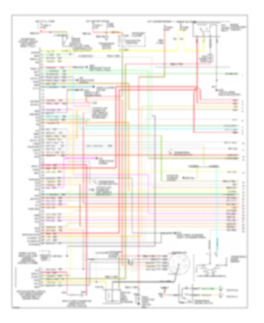
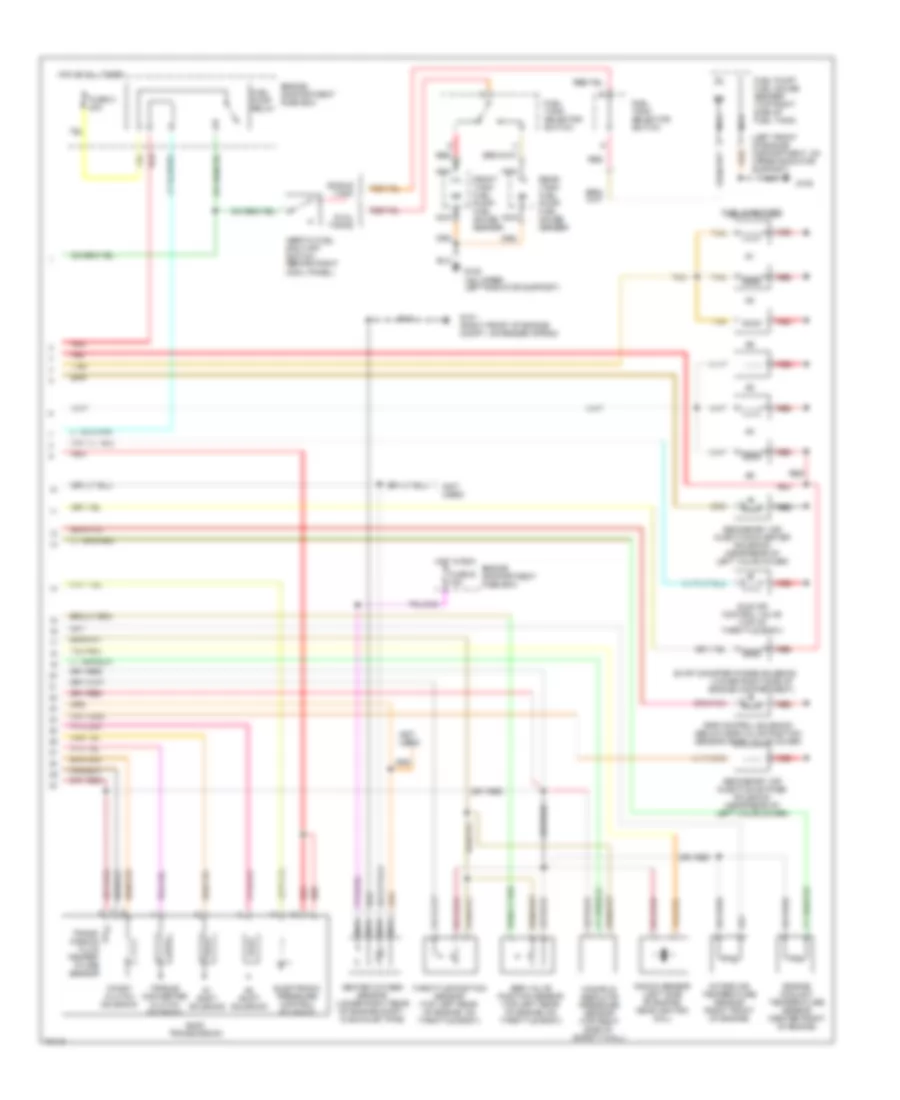
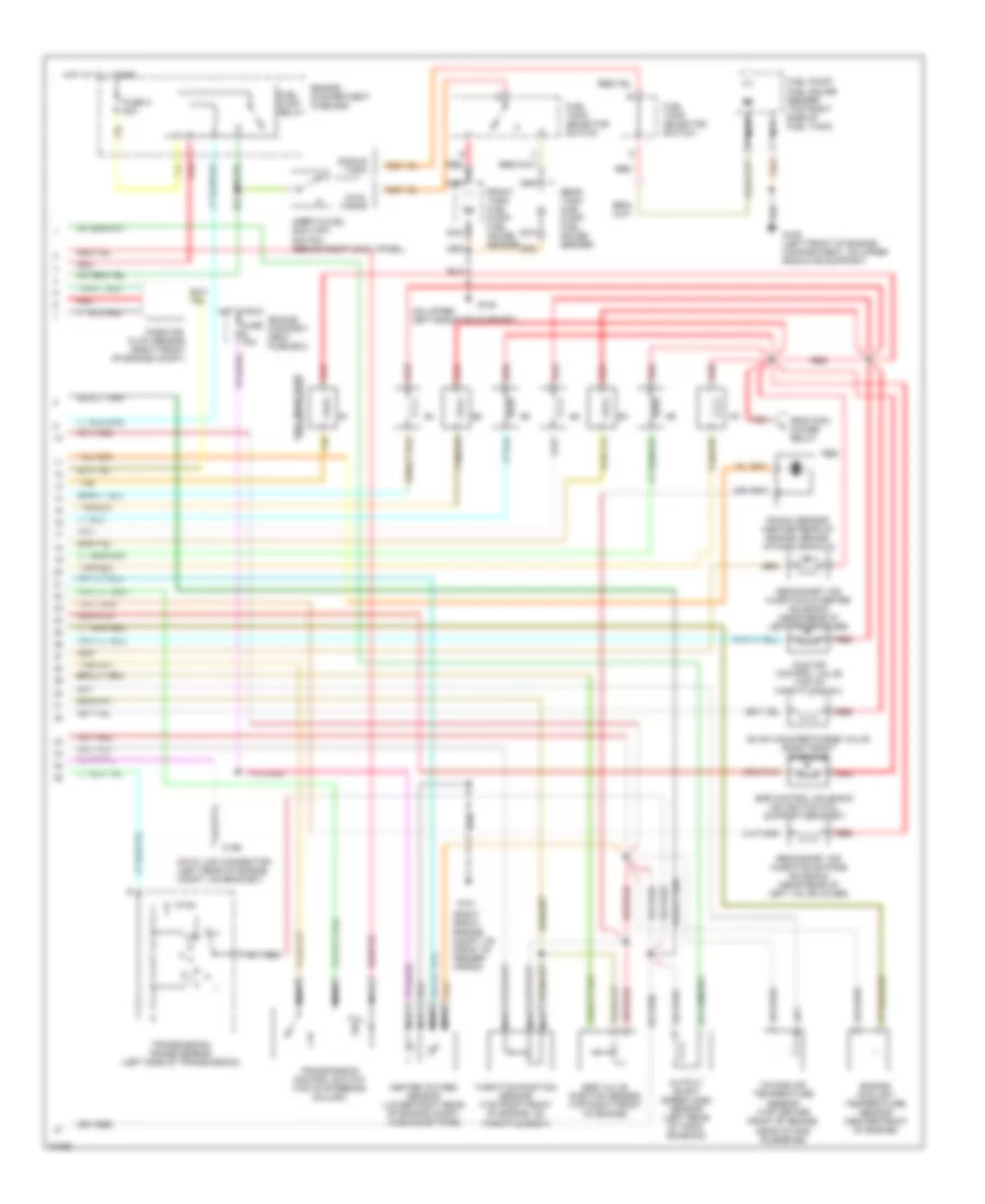
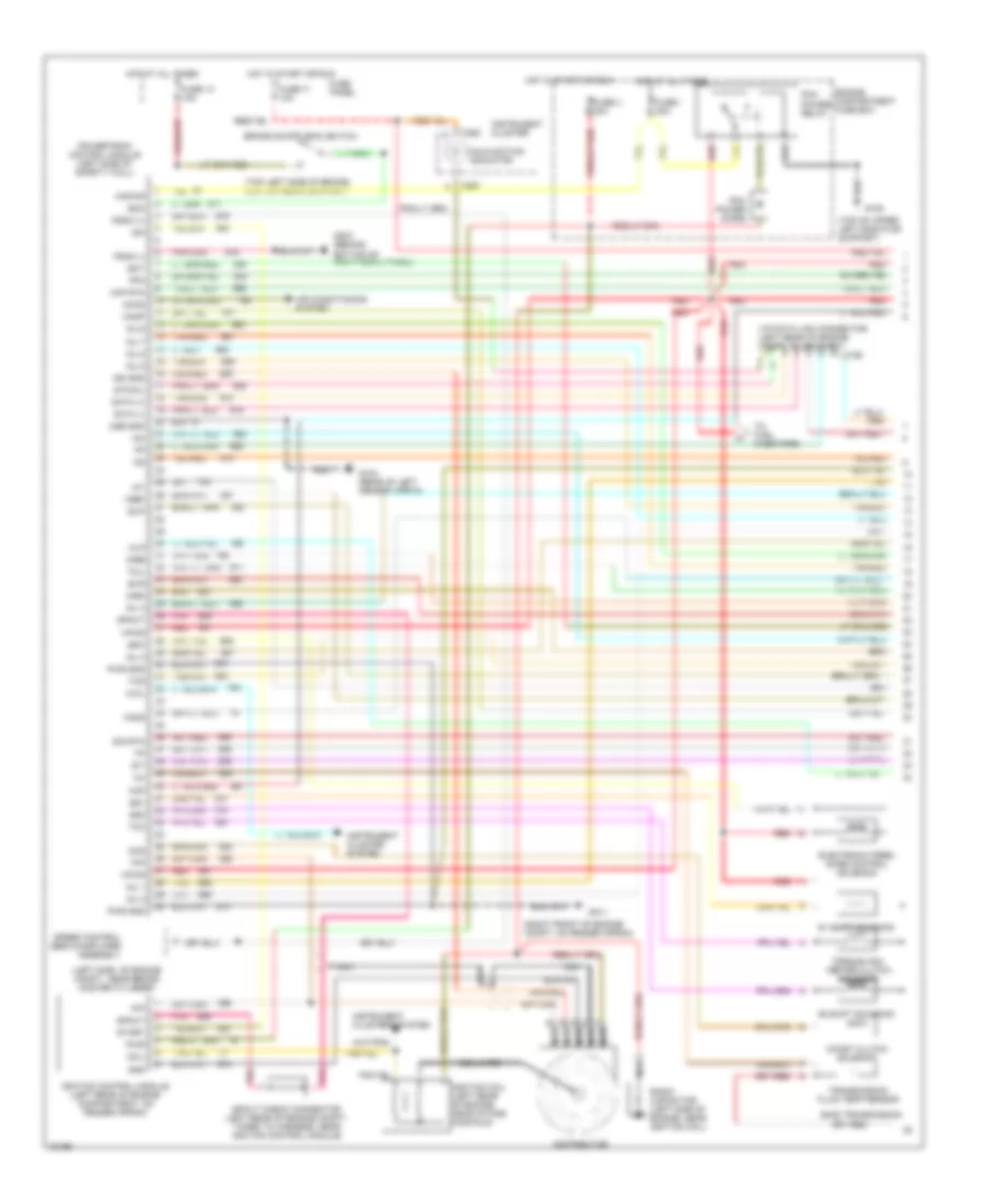
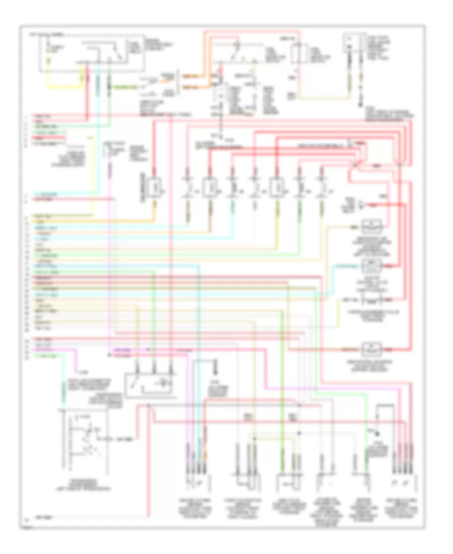
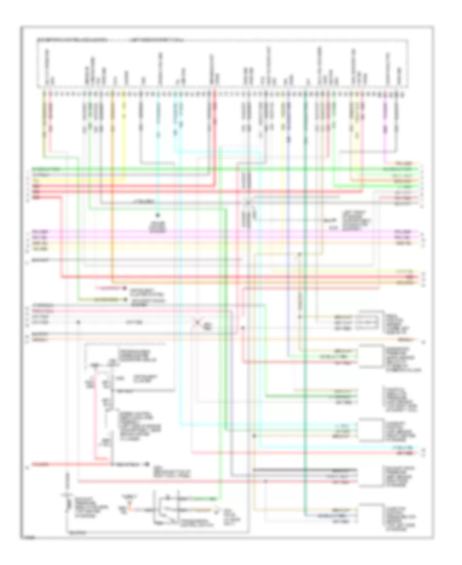
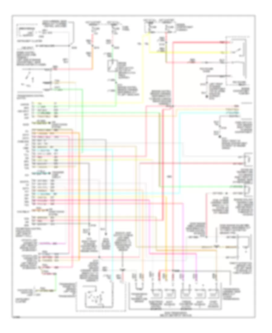
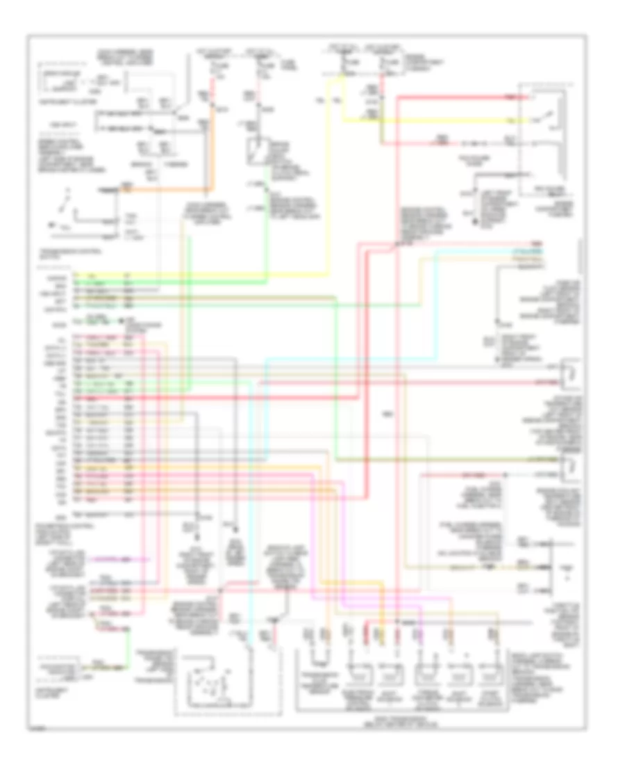
4.9L, Engine Performance Wiring Diagrams, California (1 of 2) for Ford Cab & Chassis F350 1995
List of elements for 4.9L, Engine Performance Wiring Diagrams, California (1 of 2) for Ford Cab & Chassis F350 1995:
- (199)
- * w/ e40d
- 4x4l
- A/c system
- Accs
- Air conditioning (a/c) system
- Airb
- Aird
- Boo
- Brake on/off switch (top left side of brake/clutch pedal support)
- C198
- C199
- C250
- C251
- Ccs
- Ckp
- Coil
- Coil wire
- Cse gnd
- Diode
- Distributor
- Ect
- Engine compartment fuse box
- Epc
- Epcpwr/vpwr
- Evap
- Evp
- Evr
- Fpm
- Fuel inj 1
- Fuel inj 2
- Fuel inj 3
- Fuel inj 4
- Fuel inj 5
- Fuel inj 6
- Fuel injector 5
- Fuel injector 6
- Fuel injs. 2 & 1
- Fuse 13 15a
- Fuse 17 10a
- Fuse i 20a
- Fuse panel
- Fuse u 20a
- G101 (right front of engine compt, on fender apron)
- G104 (rear of left fender apron)
- G108 (top of upper radiator support)
- G203 (behind bottom of right cowl panel)
- Gnd
- H02s (r)
- Ho2s (f)
- Hot at all times
- Hot in start or run
- Iac
- Iat
- Idm
- Ign gnd
- Ignition coil (left front of engine)
- Ignition control module (left rear of engine compartment on fender apron)
- Instrument cluster
- Instrument cluster system
- Kapwr
- Maf
- Malfunction indicator
- Nca
- Or cpp
- Pcm pin 32
- Pcm pin 41
- Pcm power relay
- Pip
- Pnk
- Powertrain control module (left side of safety wall)
- Pwr
- Pwr gnd
- Radio capacitor (near ignition coil)
- Red
- Sig rtn
- Speed control servo amplifier assembly (near brake master cylinder)
- Spout
- Spout check connector (near ignition control module)
- Ss1
- Ss2
- Start
- Starting system
- Sto/mil
- Tan
- Tcc
- Tcil
- Tcs
- Tft
- Tr *
- Transmission
- Transmission control switch
- Transmission range sensor
- Transmission switch
- Vehicle speed input
- Vip data link
- Vip data link (+)
- Vip data link (-)
- Vip data link connector
- Vip data link connector (left rear of engine compt, on bracket)
- Vpwr
- Vref
- Vss (+)
- Vss (-)
- W/ e4od
- W/ e4od only
- W/o e4od
- Wac relay
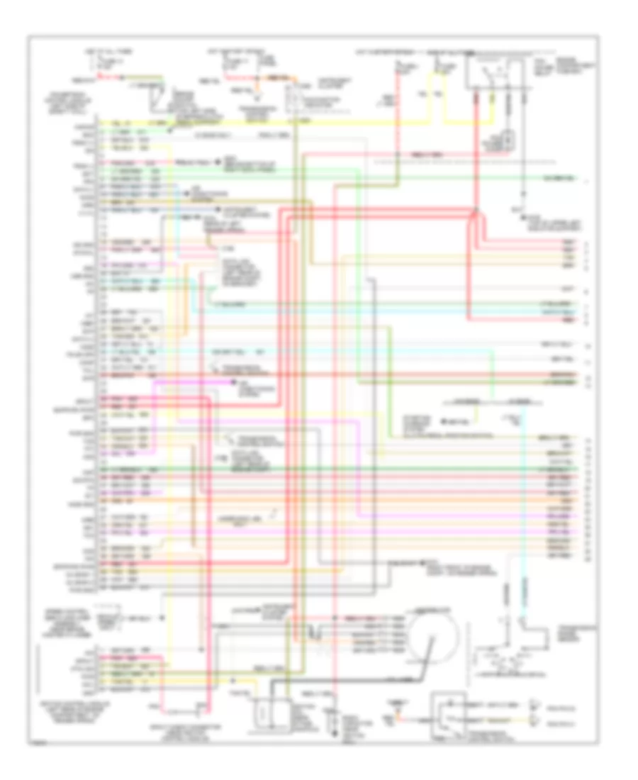
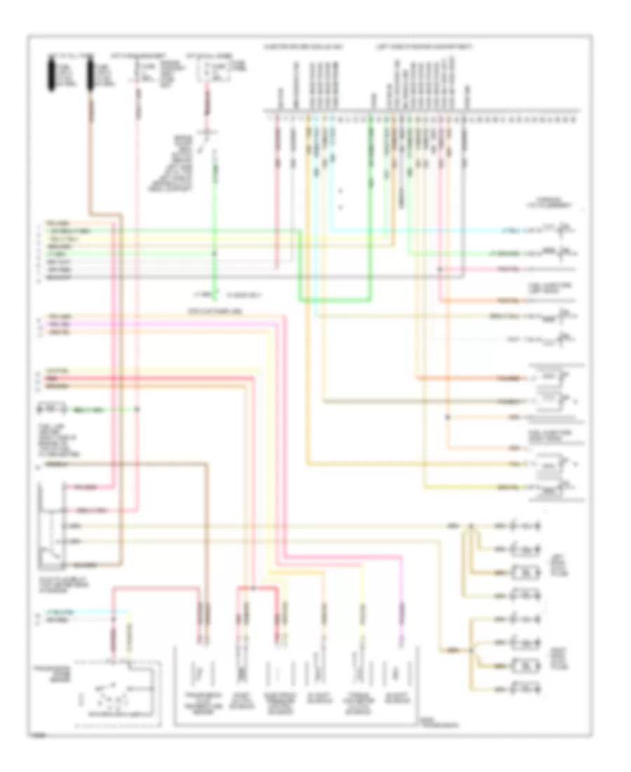
4.9L, Engine Performance Wiring Diagrams, California (2 of 2) for Ford Cab & Chassis F350 1995
List of elements for 4.9L, Engine Performance Wiring Diagrams, California (2 of 2) for Ford Cab & Chassis F350 1995:
- #1 shift solenoid
- #2 shift solenoid
- (left front of engine compartment, on upper radiator support)
- (lower right side of engine compartment)
- Coast clutch solenoid
- Dual tanks
- E40d transmission
- Egr control solenoid (left rear of engine)
- Egr valve position sensor (top left rear of engine, on throttle body)
- Electronic pressure control solenoid
- Engine compartment fuse box
- Engine coolant temp. sensor
- Engine coolant temperature sensor (center front of engine)
- Evap canister purge solenoid
- Front
- Front tank fuel pump/ fuel gauge sender
- Fuel injectors
- Fuel pump relay
- Fuel pump/ fuel gauge sender (top right side of fuel tank)
- Fuel tank selector switch
- Fuse o 20a
- G101 (right front of engine compt, on fender apron)
- G108
- Heated oxygen sensor (lower right side of engine, in exhaust pipe)
- Hot at all times
- Idle air control valve (top of throttle body)
- Inertia fuel shut-off switch (behind right cowl panel)
- Intake air temp. sensor
- Intake air temperature sensor (right front of engine)
- Knock sensor (left side of engine, near ignition coil)
- Mass air flow sensor (left side of engine compartment)
- Nca
- Pcm a
- Pcm b
- Pcm d
- Pcm e
- Pcm g
- Pcm h
- Pcm pin 25
- Pcm pin 7
- Pin 12
- Pin 15
- Pin 35
- Pin 39
- Pin 58
- Pin 59
- Rear
- Rear tank fuel pump/ fuel gauge sender
- Red
- Secondary air injection bypass solenoid (left rear of engine)
- Secondary air injection diverter solenoid (left rear of engine)
- Single tank
- Tan
- Throttle position sensor (top left rear of engine, on throttle body)
- Torque converter clutch solenoid
- Trans- mission fluid temper- ature sensor
- W/ e40d
- W/o e40d
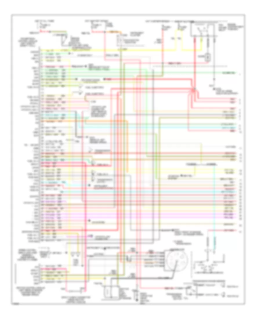
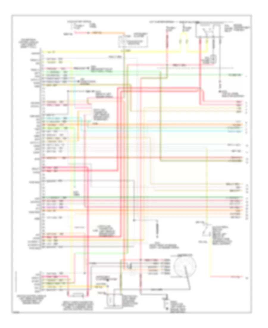
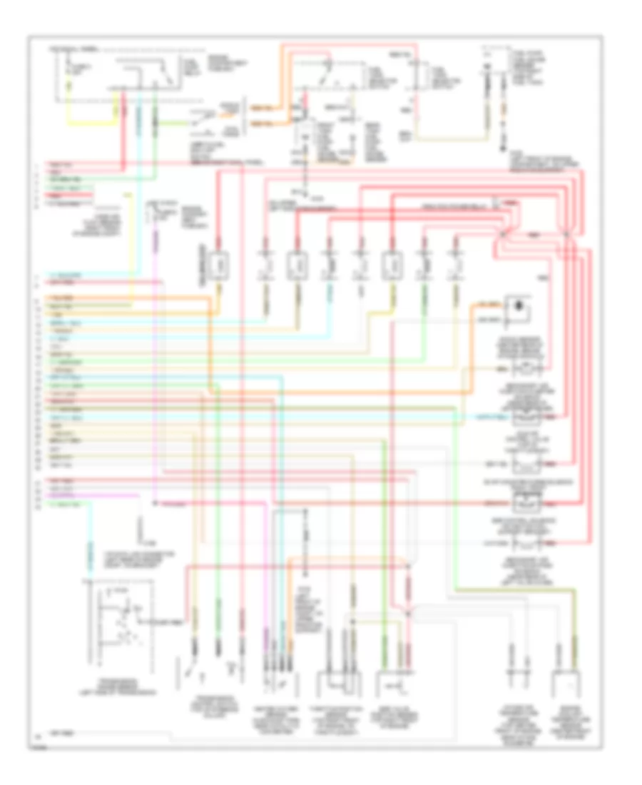
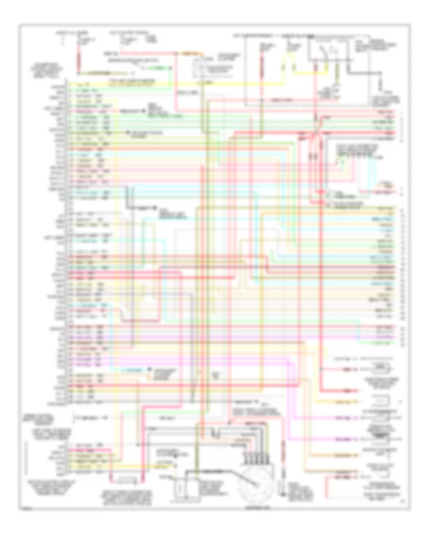
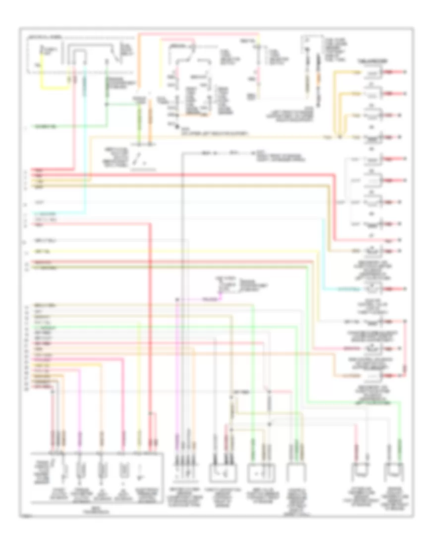
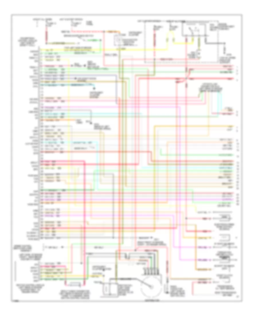
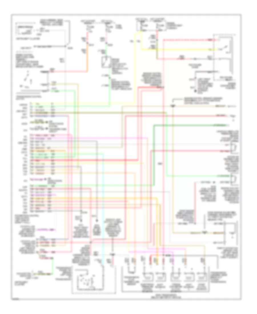
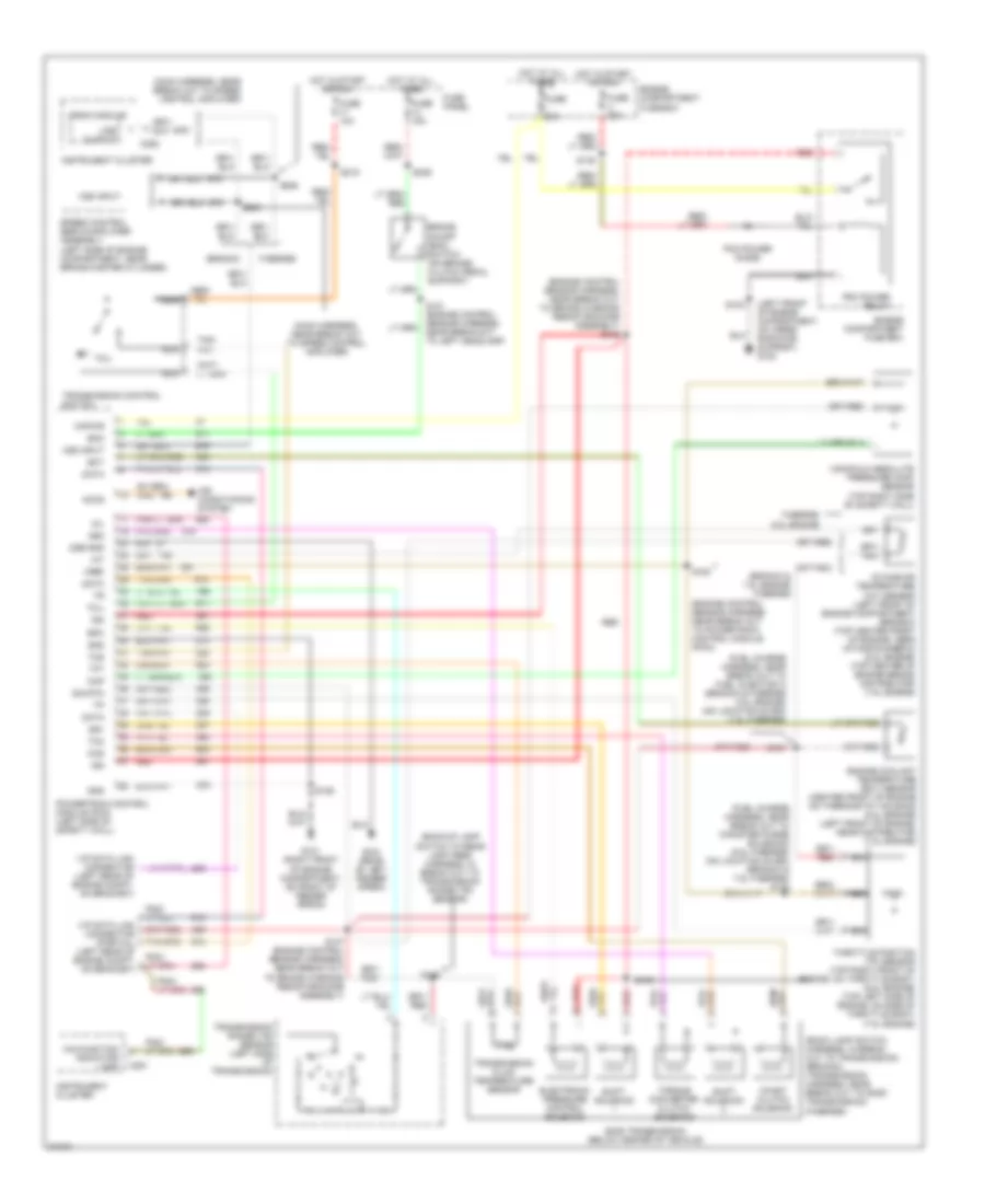
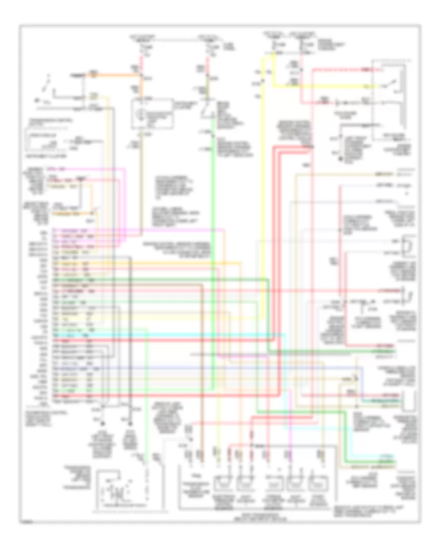
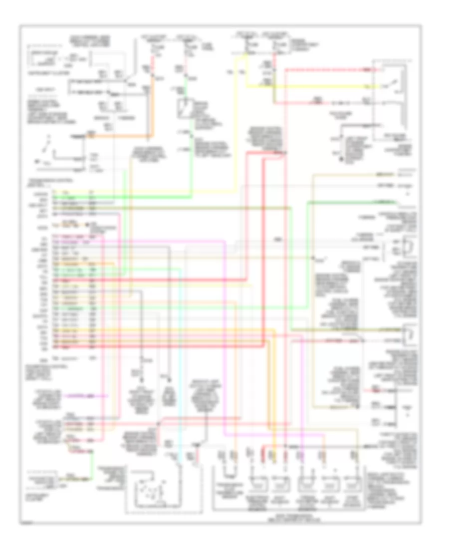
4.9L, Engine Performance Wiring Diagrams, Except California (1 of 2) for Ford Cab & Chassis F350 1995
List of elements for 4.9L, Engine Performance Wiring Diagrams, Except California (1 of 2) for Ford Cab & Chassis F350 1995:
- (199)
- 4 x 4l
- Accs
- Acd
- Air conditioning system
- Airb
- Aird
- Boo
- Brake on/off switch (top left side of brake/clutch pedal support)
- C198
- C199
- C250
- C251
- Canp
- Ccs
- Coil
- Coil wire
- Cse gnd
- Data (+)
- Data (-)
- Distributor
- Ect
- Engine compartment fuse box
- Epc
- Epcpwr/vpwr
- Evp
- Evr
- Fpm
- Fuse 13 15a
- Fuse 17
- Fuse 17 10a
- Fuse i 20a
- Fuse panel
- Fuse u 20a
- G101 (right front of engine compt, on fender apron)
- G104 (rear of left fender apron)
- G108 (top of upper radiator support)
- G203 (behind bottom of right cowl panel)
- Gnd
- Ho2s
- Ho2s gnd
- Hot at all times
- Hot in start or run
- Iac
- Iat
- Idm
- Ign gnd
- Ignition coil (left front of engine)
- Ignition control module (left rear of engine compartment on fender apron)
- Inj bank 1
- Inj bank 2
- Instr. cluster system
- Instrument cluster
- Instrument cluster system
- Kapwr
- Malfunction indicator
- Map
- Nca
- Pcm pin 32
- Pcm pin 41
- Pcm power diode
- Pcm power relay
- Pip
- Pnk
- Powertrain control module (left side of safety wall)
- Psom (+)
- Psom (-)
- Pwr
- Pwr gnd
- Radio capacitor (near ignition coil)
- Red
- Sig rtn
- Speed control servo/amplifier assembly (near brake master cylinder)
- Spout
- Spout check connector (near ignition control module)
- Ss1
- Ss2
- Start
- Starting/ charging system
- Sti
- Sto/mil
- Tan
- Tcc
- Tcil
- Tcs
- Tft
- Tr or cpp
- Transmission control switch
- Transmission range sensor
- Vehicle speed input
- Vip data link connector (left rear of engine compt)
- Vip data link connector (left rear of engine compt, on bracket)
- Vpwr
- Vref
- W/ e4od
- W/ e4od only
- W/o e4od
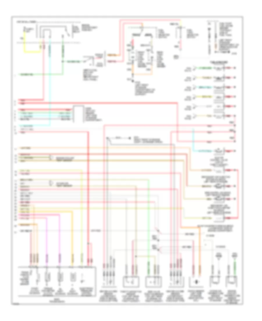
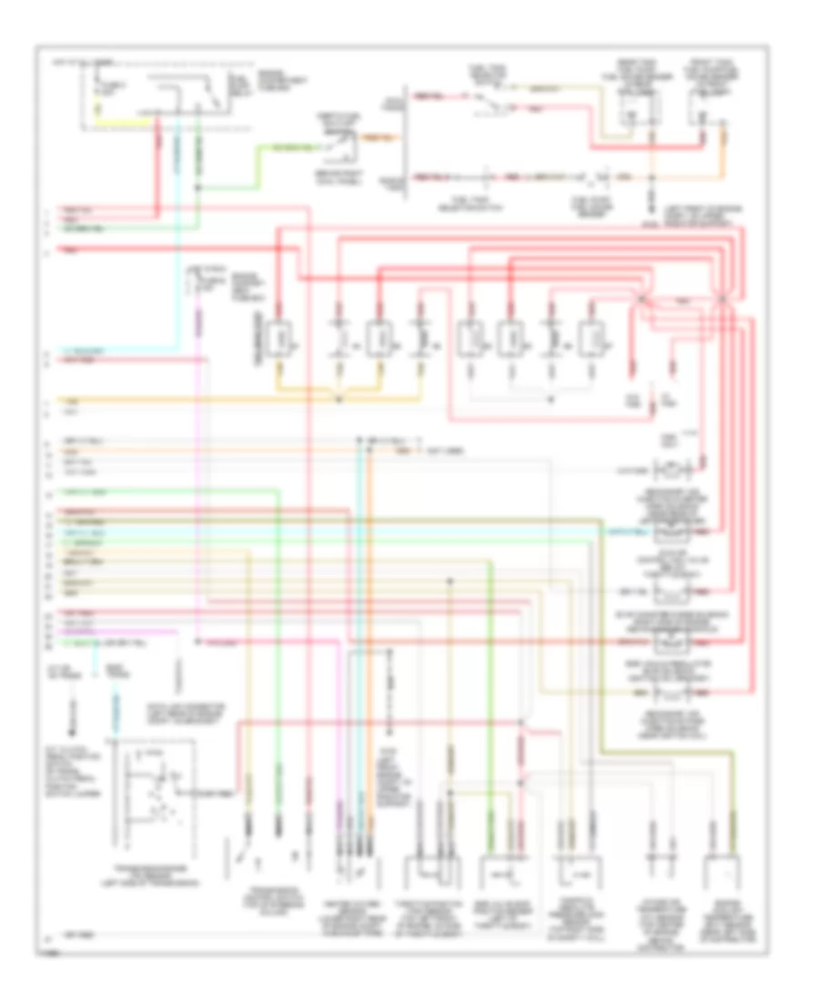
4.9L, Engine Performance Wiring Diagrams, Except California (2 of 2) for Ford Cab & Chassis F350 1995
List of elements for 4.9L, Engine Performance Wiring Diagrams, Except California (2 of 2) for Ford Cab & Chassis F350 1995:
- #1 shift solenoid
- #2 shift solenoid
- (left front of engine compartment, on upper radiator support)
- (lower right side of engine compartment)
- (not used)
- (on upper left radiator support)
- Coast clutch solenoid
- Dual tanks
- E40d transmission
- Egr control solenoid (below egr valve position sensor near valve cover)
- Egr valve position sensor (top left rear of engine, on throttle body)
- Electronic pressure control solenoid
- Engine compartment fuse box
- Engine coolant temperature sensor (center front of engine)
- Evap canister purge solenoid
- Front tank fuel pump/ fuel gauge sender
- Fuel injectors
- Fuel pump relay
- Fuel pump/ fuel gauge sender (top right side of fuel tank)
- Fuel tank selector switch
- Fuse e 15a
- Fuse o 20a
- G101 (right front of engine compt, on fender apron)
- G108
- Heated oxygen sensor (lower right rear of engine compt, in exhaust pipe)
- Hot at all times
- Hot in run
- Idle air control valve (top of throttle body)
- Inertia fuel shut-off switch (behind right cowl panel)
- Intake air temperature sensor (right front of engine)
- Knock sensor (left side of engine, near ignition coil)
- Manifold absolute pressure sensor (top right side of safety wall)
- Nca
- Rear tank fuel pump/ fuel gauge sender
- Red
- Secondary air injection bypass solenoid (near rear of left valve cover)
- Secondary air injection diverter solenoid (near rear of left valve cover)
- Single tank
- Tan
- Throttle position sensor (top left rear of engine, on throttle body)
- Torque converter clutch solenoid
- Trans- mission fluid temper- ature sensor
5.0L
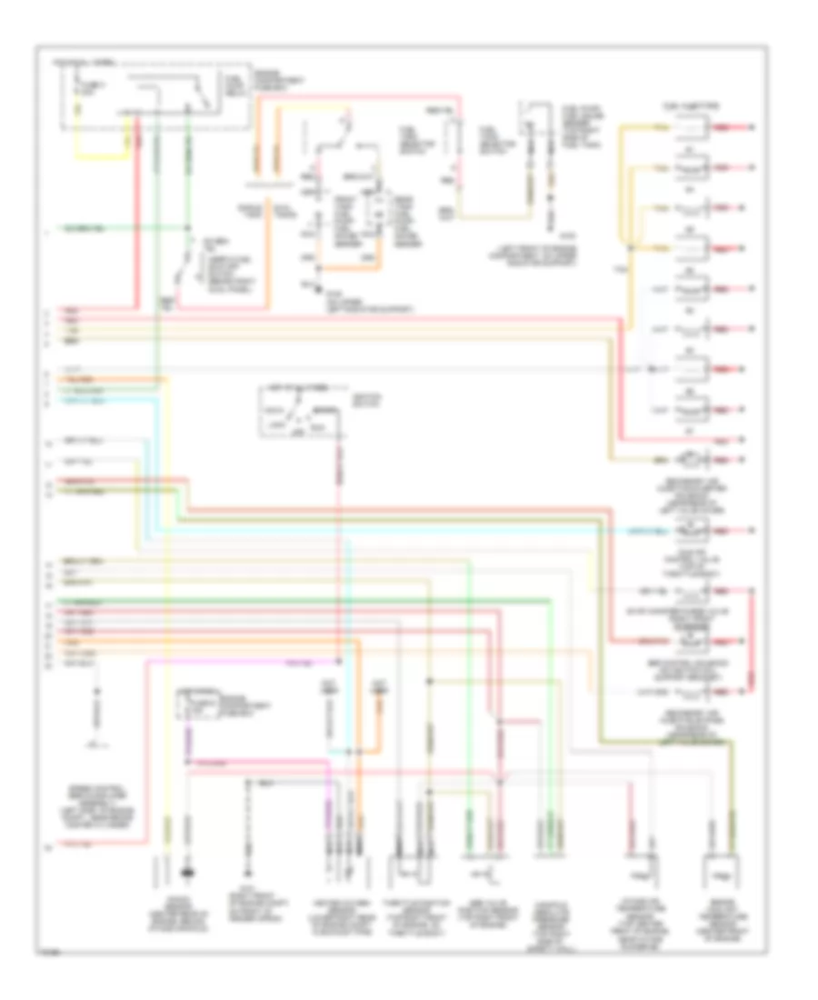
5.0L MFI, Engine Performance Wiring Diagrams (1 of 2) for Ford Cab & Chassis F350 1995
List of elements for 5.0L MFI, Engine Performance Wiring Diagrams (1 of 2) for Ford Cab & Chassis F350 1995:
- (not used)
- (right front of engine compt, on fender apron)
- Accs
- Air conditioning system
- Airb
- Aird
- C198
- C250
- C251
- Canp
- Clutch pedal position switch (behind left side of i/p, top right side of brake/clutch pedal support)
- Coil
- Coil wire
- Cpp
- Cse gnd
- Data (+)
- Data (-)
- Data link connector (left rear of engine compt, on bracket)
- Data link connector c199 (left rear of engine compt, on bracket)
- Distributor
- Ect
- Engine compartment fuse box
- Evp
- Evr
- Fpm
- Fuse 17 10a
- Fuse i 20a
- Fuse panel
- Fuse u 20a
- G101
- G104 (rear of left fender apron)
- G108 (top of upper radiator support)
- G203 (behind bottom of right cowl panel)
- Gnd
- Ho2s
- Ho2s gnd
- Hot at all times
- Hot in start or run
- Iac
- Iat
- Idm
- Ign gnd
- Ignition coil (left rear of engine, near intake manifold)
- Ignition control module (left rear of engine compartment, on fender apron)
- Inj bank 1
- Inj bank 2
- Instrument cluster
- Instrument clusters system
- Kapwr
- Malfunction indicator
- Map
- Nca
- Pcm power diode
- Pcm power relay
- Pip
- Pnk
- Powertrain control module (left side of safety wall)
- Psom (+)
- Psom (-)
- Psp
- Pwr
- Pwr gnd
- Radio capacitor (left side of engine, near ignition coil)
- Red
- Sig rtn
- Spout
- Spout check connector (left rear of engine compt, taped to harness, near ignition control module)
- Start
- Sti
- Sto/mil
- Tan
- Vpwr
- Vref
5.0L MFI, Engine Performance Wiring Diagrams (2 of 2) for Ford Cab & Chassis F350 1995
List of elements for 5.0L MFI, Engine Performance Wiring Diagrams (2 of 2) for Ford Cab & Chassis F350 1995:
- (left front of engine compartment, on upper radiator support)
- (on upper left radiator support)
- (right front of engine compt, on front of fender apron)
- (right front of engine)
- Acc
- Dual tanks
- Egr control solenoid (on ignition coil support bracket)
- Egr valve position sensor (top right front of engine)
- Engine compartment fuse box
- Engine coolant temperature sensor (center front of engine)
- Evap canister purge valve
- Front tank fuel pump/ fuel gauge sender
- Fuel injectors
- Fuel pump relay
- Fuel pump/ fuel gauge sender (top right side of fuel tank)
- Fuel tank selector switch
- Fuse e 15a
- Fuse o 20a
- G101
- G108
- Heated oxygen sensor (lower right rear of engine compt, in exhaust pipe)
- Hot at all times
- Hot in run
- Idle air control valve (top of throttle body)
- Ignition switch
- Inertia fuel shut-off switch (behind right cowl panel)
- Intake air temperature sensor (top center front of engine, near intake runner #6)
- Knock sensor (center rear of engine, behind intake manifold)
- Lock
- Manifold absolute pressure sensor (top right side of safety wall)
- Nca
- Not used
- Off
- Rear tank fuel pump/ fuel gauge sender
- Red
- Run
- Secondary air injection bypass solenoid (near rear of left valve cover)
- Secondary air injection diverter solenoid (near rear of left valve cover)
- Single tank
- Speed control servo/amplifier assembly) (left side of engine compt., near brake master cylinder)
- Start
- Tan
- Throttle position sensor (top right front of engine, on throttle body)
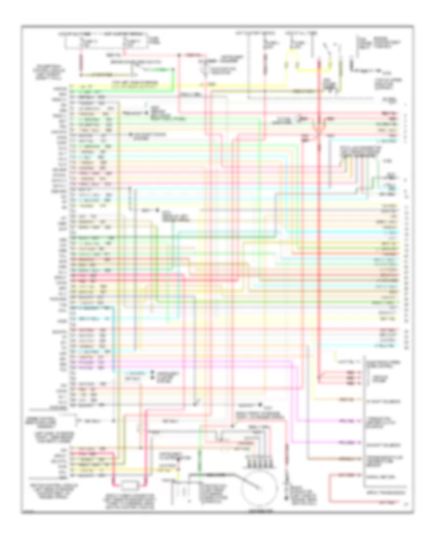
5.0L SFI, Engine Performance Wiring Diagrams, with 4R70W Transmission (1 of 2) for Ford Cab & Chassis F350 1995
List of elements for 5.0L SFI, Engine Performance Wiring Diagrams, with 4R70W Transmission (1 of 2) for Ford Cab & Chassis F350 1995:
- #1 shift solenoid
- #2 shift solenoid
- (left side of engine compt., near brake master cylinder)
- (right front of engine compt, on fender apron)
- (top left side of brake/ clutch pedal support)
- (top of upper radiator support)
- 4r70w transmission
- 4x4l
- Accs
- Air conditioning system
- Airb
- Aird
- Boo
- Brake on/off (boo) switch
- C198
- C250
- C251
- Canp
- Coil
- Coil wire
- Cse gnd
- Data (+)
- Data (-)
- Data link connector (left rear of engine compt, on bracket)
- Distributor
- Ect
- Electronic pres-
- Engine compartment fuse box
- Epc
- Evp
- Evr
- Fpm
- Fuse 13 15a
- Fuse 17 10a
- Fuse i 20a
- Fuse panel
- Fuse u 20a
- G101
- G104 (rear of left fender apron)
- G108
- G203 (behind bottom of right cowl panel)
- Gnd
- Ho2s
- Hot at all times
- Hot in start or run
- Iac
- Iat
- Idm
- Idm (fto)
- Ign gnd
- Ignition coil (left rear of engine, near intake manifold)
- Ignition control module (left rear of engine compartment, on fender apron)
- Inj 1
- Inj 2
- Inj 3
- Inj 4
- Inj 5
- Inj 6
- Inj 7
- Inj 8
- Instrument cluster
- Instrument cluster system
- Kapwr
- Maf
- Maf rtn
- Malfunction indicator
- Mlp
- Nca
- Oss
- Pcm
- Pcm power relay
- Pip
- Pnk
- Power diode
- Powertrain control module (left side of safety wall)
- Psom (+)
- Psom (-)
- Pwr
- Pwr gnd
- Radio capacitor (left side of engine, near ignition coil)
- Red
- Sig rtn
- Signal return
- Solenoid
- Speed control servo/amplifier assembly
- Spout
- Spout check connector (left rear of engine compt, taped to harness, near ignition control module)
- Ss1
- Ss2
- Sti
- Sto/mil
- Sure control
- Tan
- Tan/red
- Tcc
- Tcil
- Tcs
- Tfi
- To fuel injectors
- Torque con- verter clutch
- Transmission fluid temperature sensor
- Vehicle power
- Vpwr
- Vref
5.0L SFI, Engine Performance Wiring Diagrams, with 4R70W Transmission (2 of 2) for Ford Cab & Chassis F350 1995
List of elements for 5.0L SFI, Engine Performance Wiring Diagrams, with 4R70W Transmission (2 of 2) for Ford Cab & Chassis F350 1995:
- (on upper left radiator support)
- (right front engine compt, 0n front of fender apron)
- C199
- Data link connector (left rear of engine compt, on bracket)
- Dual tanks
- Egr control solenoid (on ignition coil support bracket)
- Egr valve position sensor (top right front of engine)
- Engine compart- ment fuse box
- Engine compartment fuse box
- Engine coolant temperature sensor (center front of engine)
- Evap canister purge valve (right front of engine)
- From pcm power relay
- Front tank fuel pump/ fuel gauge sender
- Fuel injectors
- Fuel pump relay
- Fuel pump/ fuel gauge sender (top right side of fuel tank)
- Fuel tank selector switch
- Fuse e 15a
- Fuse o 20a
- G101
- G108
- G108 (left front of engine compartment, on upper radiator support)
- Heated oxygen sensor (lower right rear of engine compt, in exhaust pipe)
- Hot at all times
- Hot in run
- Idle air control valve (top of throttle body)
- Inertia fuel shut-off switch (behind right cowl panel)
- Intake air temperature sensor (top center front of engine, near intake runner #6)
- Knock sensor (center rear of engine, behind intake manifold)
- Mass air flow sensor (right front of engine compt)
- Nca
- Output shaft speed (oss) sensor (left rear of tran- smission)
- Rear tank fuel pump/ fuel gauge sender
- Red
- Secondary air injection bypass solenoid (near rear of left valve cover)
- Secondary air injection diverter solenoid (near rear of left valve cover)
- Single tank
- Tan
- Tan/red
- Tcil
- Throttle position sensor (top right front of engine, on throttle body)
- Transmission control switch (top of steering column)
- Transmission range sensor (left side of transmission)
5.0L SFI, Engine Performance Wiring Diagrams, with E4OD Transmission (1 of 2) for Ford Cab & Chassis F350 1995
List of elements for 5.0L SFI, Engine Performance Wiring Diagrams, with E4OD Transmission (1 of 2) for Ford Cab & Chassis F350 1995:
- #1 shift solenoid
- #2 shift solenoid
- (left side of engine compt., near brake master cylinder)
- (right front of engine compt, on fender apron)
- (top left side of brake/ clutch pedal support)
- (top of upper left radiator support)
- 4x4l
- Accs
- Air conditioning system
- Airb
- Aird
- Boo
- Brake on/off (boo) switch
- C198
- C250
- C251
- Canp
- Ccs
- Coast clutch solenoid
- Coil
- Coil wire
- Cse gnd
- Data (+)
- Data (-)
- Distributor
- E40d transmission
- Ect
- Electronic pres- sure control solenoid
- Engine compartment fuse box
- Epc
- Evp
- Evr
- Fpm
- Fuse 13 15a
- Fuse 17 10a
- Fuse i 20a
- Fuse panel
- Fuse u 20a
- G101
- G104 (rear of left fender apron)
- G108
- G203 (behind bottom of right cowl panel)
- Gnd
- Ho2s
- Hot at all times
- Hot in start or run
- Iac
- Iat
- Idm
- Ign gnd
- Ignition coil (left rear of engine, near intake manifold)
- Ignition control module (left rear of engine compartment, on fender apron)
- Inj 1
- Inj 2
- Inj 3
- Inj 4
- Inj 5
- Inj 6
- Inj 7
- Inj 8
- Instrument cluster
- Instrument cluster system
- Instrument clusters system
- Kapwr
- Maf
- Maf rtn
- Malfunction indicator
- Mlp
- Nca
- Pcm power diode
- Pcm power relay
- Pip
- Pnk
- Powertrain control module (left side of safety wall)
- Psom (+)
- Psom (-)
- Pwr
- Pwr gnd
- Radio capacitor (left side of engine, near ignition coil)
- Red
- Sig rtn
- Speed control servo/amplifier assembly
- Spout
- Spout check connector (left rear of engine compt, taped to harness, near ignition control module)
- Ss1
- Ss2
- Start
- Sti
- Sto/mil
- Tan
- Tan/red
- Tcc
- Tcil
- Tcs
- Tfi
- To fuel injectors
- Torque con- verter clutch solenoid
- Transmission fluid temp sensor
- Vip data link connector (left rear of engine compt, on bracket)
- Vpwr
- Vref
5.0L SFI, Engine Performance Wiring Diagrams, with E4OD Transmission (2 of 2) for Ford Cab & Chassis F350 1995
List of elements for 5.0L SFI, Engine Performance Wiring Diagrams, with E4OD Transmission (2 of 2) for Ford Cab & Chassis F350 1995:
- (left front of engine compt, 0n upper radiator support)
- (on upper left radiator support)
- Dual tanks
- Egr control solenoid (on ignition coil support bracket)
- Egr valve position sensor (top right front of engine)
- Engine compart- ment fuse box
- Engine compartment fuse box
- Engine coolant temperature sensor (center front of engine)
- Evap canister purge solenoid (right front of engine)
- From pcm power relay
- Front tank fuel pump/ fuel gauge sender
- Fuel injectors
- Fuel pump relay
- Fuel pump/ fuel gauge sender (top right side of fuel tank)
- Fuel tank selector switch
- Fuse e 15a
- Fuse o 20a
- G108
- G108 (left front of engine compartment, on upper radiator support)
- Heated oxygen sensor (in exhaust pipe, near catalytic converter)
- Hot at all times
- Hot in run
- Idle air control valve (top of throttle body)
- Inertia fuel shut-off switch (behind right cowl panel)
- Intake air temperature sensor (top center front of engine, near intake runner #6)
- Knock sensor (center rear of engine, behind intake manifold)
- Mass air flow sensor (right front of engine compt)
- Nca
- Rear tank fuel pump/ fuel gauge sender
- Red
- Secondary air injection bypass solenoid (near rear of left valve cover)
- Secondary air injection diverter solenoid (near rear of left valve cover)
- Single tank
- Tan
- Tan/red
- Tcil
- Throttle position sensor (top right front of engine, on throttle body)
- Transmission control switch (top of steering column)
- Transmission range sensor (left side of transmission)
- Vip data link connector (left rear of engine compt, on bracket)
5.8L
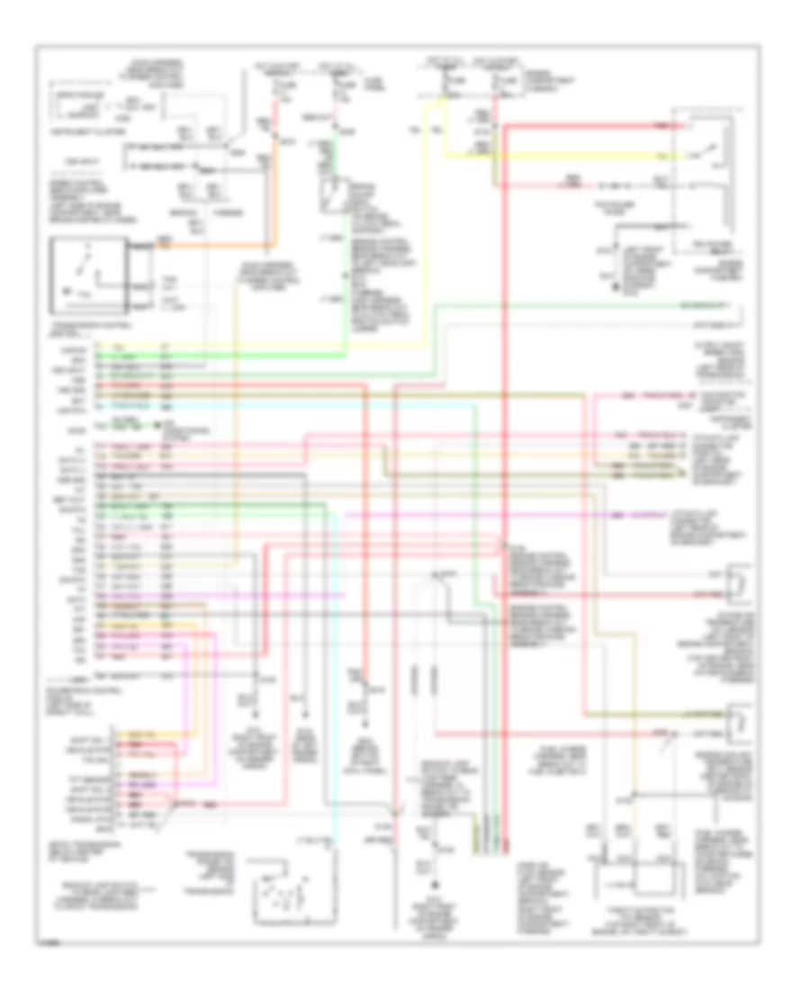
5.8L, Engine Performance Wiring Diagrams, California (1 of 2) for Ford Cab & Chassis F350 1995
List of elements for 5.8L, Engine Performance Wiring Diagrams, California (1 of 2) for Ford Cab & Chassis F350 1995:
- #1 shift solenoid
- #2 shift solenoid
- (left side of engine compt., near brake master cylinder)
- (not used)
- (right front of engine compt, on fender apron)
- (top left side of brake/ clutch pedal support)
- (top of upper left radiator support)
- 4x4l
- Accs
- Air conditioning system
- Aird
- Boo
- Brake on/off (boo) switch
- C198
- C250
- C251
- Canp
- Ccs
- Coast clutch solenoid
- Coil
- Coil wire
- Cse gnd
- Data (+)
- Data (-)
- Data link connector (left rear of engine compt, on bracket)
- Distributor
- E40d transmission
- Ect
- Electronic pres- sure control solenoid
- Engine compartment fuse box
- Epc
- Evap canister purge valve
- Evp
- Evr
- Fpm
- Fuel injectors
- Fuse 13 15a
- Fuse 17 10a
- Fuse i 20a
- Fuse panel
- Fuse u 20a
- G101
- G104 (rear of left fender apron)
- G108
- G203 (behind bottom of right cowl panel)
- Gnd
- Ho2s
- Hot at all times
- Hot in start or run
- Iac
- Iat
- Idm
- Idm (fto)
- Ign gnd
- Ignition coil (left rear of engine compartment)
- Ignition control module (left rear of engine compartment, on fender apron)
- Inj 1
- Inj 2
- Inj 3
- Inj 4
- Inj 5
- Inj 6
- Inj 7
- Inj 8
- Instrument cluster
- Instrument cluster system
- Kapwr
- Maf
- Maf rtn
- Malfunction indicator
- Mlp
- Nca
- Pcm power diode
- Pcm power relay
- Pip
- Pnk
- Powertrain control module (left side of safety wall)
- Psom (+)
- Psom (-)
- Pwr
- Pwr gnd
- Radio capacitor (left side of engine, near ignition coil)
- Red
- Sig rtn
- Speed control servo/amplifier assembly
- Spout
- Spout check connector (left rear of engine compt, taped to harness, near ignition control module)
- Ss1
- Ss2
- Sti
- Sto/mil
- Tan
- Tan/red
- Tcc
- Tcil
- Tcs
- Tfi
- Torque con- verter clutch solenoid
- Transmission fluid temp sensor
- Vpwr
- Vref
5.8L, Engine Performance Wiring Diagrams, California (2 of 2) for Ford Cab & Chassis F350 1995
List of elements for 5.8L, Engine Performance Wiring Diagrams, California (2 of 2) for Ford Cab & Chassis F350 1995:
- (on upper left radiator support)
- (on upper radiator support)
- C199
- Data link connector (left rear of engine compt, on bracket)
- Dual tanks
- Egr control solenoid (on ignition coil support bracket)
- Egr valve position sensor (top right front of engine)
- Engine compart- ment fuse box
- Engine compartment fuse box
- Engine coolant temperature sensor (center front of engine)
- From pcm power relay
- Front tank fuel pump/ fuel gauge sender
- Fuel injectors
- Fuel pump relay
- Fuel pump/ fuel gauge sender (top right side of fuel tank)
- Fuel tank selector switch
- Fuse e 15a
- Fuse o 20a
- G108
- G108 (left front of engine compartment, on upper radiator support)
- G108 (on upper radiator support)
- Heated oxygen sensor (in exhaust pipe, near catalytic converter)
- Hot at all times
- Hot in run
- Idle air control valve (top of throttle body)
- Inertia fuel shut-off switch (behind right cowl panel)
- Intake air temperature sensor (top center front of engine, near intake runner #6)
- Mass air flow sensor (right front of engine compt)
- Nca
- Rear tank fuel pump/ fuel gauge sender
- Red
- Secondary air injection diverter solenoid (near rear of left valve cover)
- Single tank
- Tan
- Tan/red
- Tcil
- Throttle position sensor (top right front of engine, on throttle body)
- Transmission control switch (top of steering column)
- Transmission range sensor (left side of transmission)
- Vapor management valve (right front of engine)
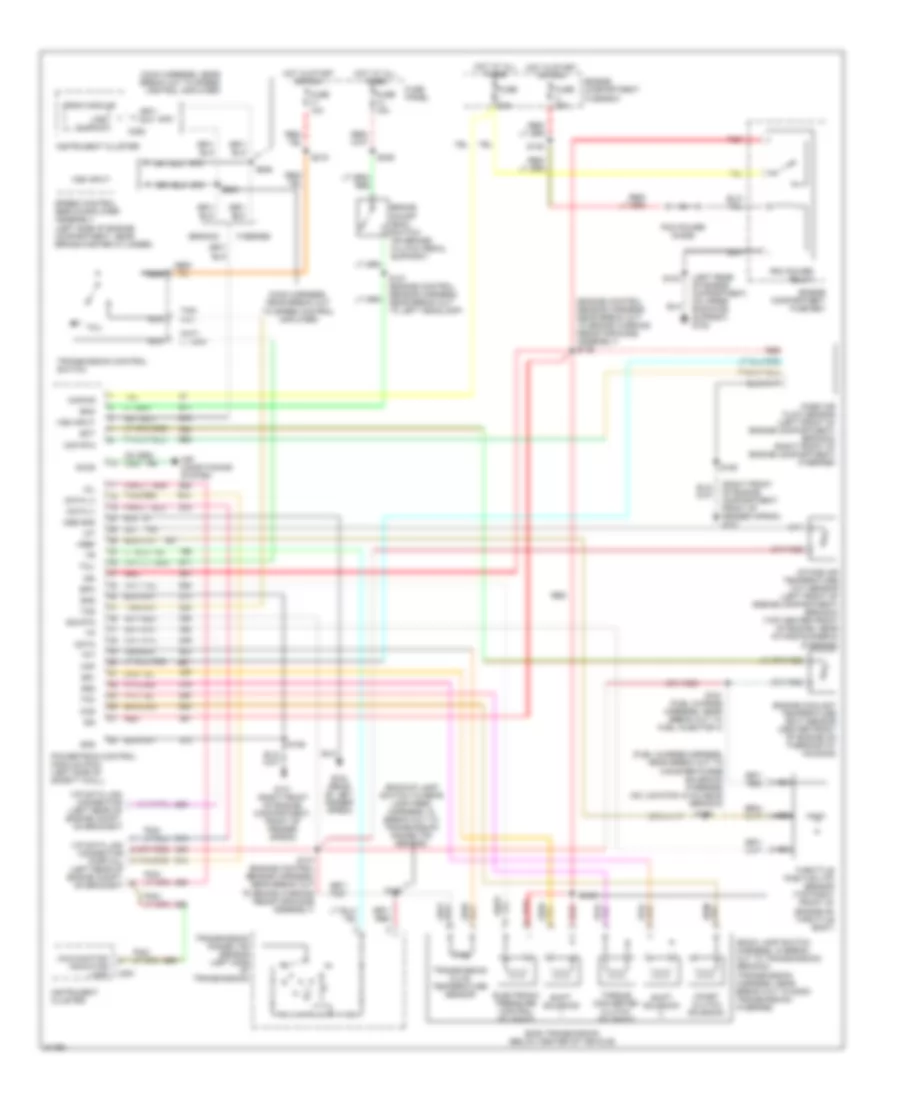
5.8L, Engine Performance Wiring Diagrams, Except California (1 of 2) for Ford Cab & Chassis F350 1995
List of elements for 5.8L, Engine Performance Wiring Diagrams, Except California (1 of 2) for Ford Cab & Chassis F350 1995:
- (fto) idm
- 4 x 4l
- Accs
- Acd
- Air conditioning system
- Airb
- Aird
- Boo
- Brake on/off switch (top left side of brake/clutch pedal support)
- C198
- C199
- C250
- C251
- Canp
- Ccs
- Coil
- Coil wire
- Cse gnd
- Data (+)
- Data (-)
- Data link connector (left rear of engine compt)
- Data link connector (left rear of engine compt, on bracket)
- Distributor
- Ecppwr/vpwr
- Ect
- Engine compartment fuse box
- Epc
- Epcpwr/vpwr
- Evp
- Evr
- Fpm
- Fuse 13 15a
- Fuse 17
- Fuse 17 10a
- Fuse i 20a
- Fuse panel
- Fuse u 20a
- G101 (right front of engine compt, on fender apron)
- G104 (rear of left fender apron)
- G108 (top of upper left radiator support)
- G203 (behind bottom of right cowl panel)
- Gnd
- Ho2s
- Ho2s gnd
- Hot at all times
- Hot in start or run
- Iac
- Iat
- Idm
- Ign gnd
- Ignition coil (near intake manifold)
- Ignition control module (left rear of engine compartment, on fender apron)
- Inj bank 1
- Inj bank 2
- Instrument cluster
- Instrument cluster system
- Kapwr
- Malfunction indicator
- Map
- Nca
- Pcm pin 32
- Pcm pin 41
- Pcm power diode
- Pcm power relay
- Pip
- Pnk
- Powertrain control module (left side of safety wall)
- Psom (+)
- Psom (-)
- Pwr
- Pwr gnd
- Radio capacitor (near ignition coil)
- Red
- Sig rtn
- Speed control servo amplifier assembly (near brake master cylinder)
- Spout
- Spout check connector (near ignition control module)
- Ss1
- Ss2
- Starting/ charging system (clutch pedal position switch)
- Sti
- Sto/mil
- Tan
- Tcc
- Tcil
- Tcs
- Tft
- Tr or cpp
- Transmission control switch
- Transmission range sensor
- Under 85oo lbs. only
- Vehicle speed input
- Vref
- W/ e4od
- W/ e4od only
- W/o e4od
5.8L, Engine Performance Wiring Diagrams, Except California (2 of 2) for Ford Cab & Chassis F350 1995
List of elements for 5.8L, Engine Performance Wiring Diagrams, Except California (2 of 2) for Ford Cab & Chassis F350 1995:
- #1 shift solenoid
- #2 shift solenoid
- (on upper left radiator support)
- Canister purge solenoid (lower right side of engine compartment)
- Coast clutch solenoid
- Dual tanks
- E40d transmission
- Egr control solenoid (on ignition coil support bracket)
- Egr valve position sensor (top right front of engine)
- Electronic pressure control solenoid
- Engine compartment fuse box
- Engine coolant temperature sensor (center front of engine)
- Front tank fuel pump/ fuel gauge sender
- Fuel injectors
- Fuel pump relay
- Fuel pump/ fuel gauge sender (top right side of fuel tank)
- Fuel tank selector switch
- Fuse e 15a
- Fuse o 20a
- G101 (right front of engine compt, on fender apron)
- G108
- G108 (left front of engine compartment, on upper radiator support)
- Heated oxygen sensor (lower right rear of engine compt, in exhaust pipe)
- Hot at all times
- Hot in run
- Idle air control valve (top of throttle body)
- Inertia fuel shut-off switch (behind right cowl panel)
- Intake air temperature sensor (top center front of engine)
- Manifold absolute pressure sensor (top right side of safety wall)
- Nca
- Rear tank fuel pump/ fuel gauge sender
- Red
- Secondary air injection bypass solenoid (near rear of left valve cover)
- Secondary air injection diverter solenoid (near rear of left valve cover)
- Single tank
- Tan
- Throttle position sensor (top right front of engine)
- Torque converter clutch solenoid
- Trans- mission fluid temper- ature sensor
7.3L
7.3L DI Turbo Diesel, Engine Performance Wiring Diagrams (1 of 3) for Ford Cab & Chassis F350 1995
List of elements for 7.3L DI Turbo Diesel, Engine Performance Wiring Diagrams (1 of 3) for Ford Cab & Chassis F350 1995:
- "wait to start" indicator
- (224 or 306)
- (left side of safety wall)
- 4x4 hi/low indicator switch (front of transfer case)
- Aat
- Acc
- Ambient air temper- ature (aat) sensor (right front of engine compartment)
- Brake press sw
- Brake pressure switch (near left front rail)
- Brake warning ind
- C250
- C251
- C264
- Clutch pedal position switch (top right side of brake/clutch pedal support)
- Cruise control system
- Diesel warning lamps display (top left side of i/p, right of instrument cluster)
- Ebp
- Engine compartment fuse box
- Engine oil temperature (eot) sensor (front top of engine)
- Eot
- Fuse 10a
- Fuse 3a
- Fuse e 15a
- Fuse h 30a
- Fuse i 20a
- Fuse panel
- Fuse u 30a
- G104 (rear of left fender apron)
- G108 (left front of engine compart- ment, on upper radiator support)
- Generic scan tool
- Generic scan tool (partial) (behind lower center of i/p)
- Hot at all times
- Hot in run
- Hot in run or start
- Idle pos sw
- Idle position switch (closed at idle) (near accele- rator pedal)
- Idm relay
- Ignition switch
- Injection pressure regulator (ipr) (top center of engine)
- Instrument cluster
- Instrument cluster system
- Lock
- Low range 4x4 sw
- Malfunction indicator lamp (mil)
- Map
- Off
- Pcm dlc
- Pcm power relay
- Power diode
- Powertrain control module (pcm)
- Pwr gnd
- Red
- Rpm ctrl
- Run
- Selectable rpm control (behind center of i/p)
- Speed ctrl gnd
- Ss1
- Ss2
- Start
- Tcc
- Tcs or cpp
- Tft
- Transmission control switch
- Vss gnd
- W/ e4od
- W/ e4od only
- W/o e4od
7.3L DI Turbo Diesel, Engine Performance Wiring Diagrams (2 of 3) for Ford Cab & Chassis F350 1995
List of elements for 7.3L DI Turbo Diesel, Engine Performance Wiring Diagrams (2 of 3) for Ford Cab & Chassis F350 1995:
- (left front of engine compartment, on radiator support)
- (left side of safety wall)
- (w/ e4od only)
- A/c cyl press sw
- Accl pdl pos sens
- Air conditioning system
- Baro
- Barometric pressure (baro) sensor (below i/p, at base of steering column)
- Boo
- C252
- Cam pos sens
- Camshaft position (cmp) sensor (front center of engine)
- Ccs
- Cid sig
- Cmp rtn
- Cruise control system
- Epc
- Epr
- Exhaust back pressure (ebp) sensor (right side of engine)
- Exhaust pressure regulator (epr) (top center of engine)
- Fuel delivery sig
- Fuse 17
- G108
- G203 (behind bottom of right cowl panel)
- Glow plug ctrl
- Gnd
- Icp
- Idm enable out
- Idm sig in
- Injection control pressure (icp) sensor (top left side of engine)
- Instrument cluster
- Instrument cluster system
- Ipr
- Kapwr
- Manifold absolute pressure (map) sensor (top right side of safety wall
- Nca
- Pcm pin 29
- Pedal position sensor (under left side of i/p)
- Powertrain control module (pcm)
- Programmable speedometer/ odometer module
- Pwr gnd
- Red
- Sig rtn
- Speed control servo/amplifier assembly (left side of engine compartment, near brake master cylinder)
- Speed ctrl gnd
- Tac
- Tcil
- Tcs
- Transmission control switch
- Vpwr
- Vref
- Vss
- Vss out
- Wait to start out
7.3L DI Turbo Diesel, Engine Performance Wiring Diagrams (3 of 3) for Ford Cab & Chassis F350 1995
List of elements for 7.3L DI Turbo Diesel, Engine Performance Wiring Diagrams (3 of 3) for Ford Cab & Chassis F350 1995:
- #1 shift solenoid
- #2 shift solenoid
- (for customer use)
- (left side of engine compartment)
- Brake on/off (boo) switch (behind left side of i/p, top left side of brake/clutch pedal support)
- Cid sig in
- Coast clutch solenoid
- E4od transmission
- Electronic pressure control solenoid
- Engine compart- ment fuse box
- Fuel delivery sig
- Fuel inj feed left
- Fuel inj feed right
- Fuel injector #1
- Fuel injector #1 fuel injector #8
- Fuel injector #2
- Fuel injector #3
- Fuel injector #4
- Fuel injector #5
- Fuel injector #6
- Fuel injector #7
- Fuel injectors (left bank)
- Fuel injectors (right bank)
- Fuel line heater (right side of engine, on top of fuel filter/heater)
- Fuse 15a
- Fuse panel
- Fuse u 30a
- Glow plug relay (top center rear of engine)
- Hot at all times
- Hot in run or start
- Idm feedback sig
- Inj shield gnd
- Injector driver module (idm)
- Left bank glow plugs
- Nca
- Pwr gnd
- Red
- Right bank glow plugs
- Sig rtn
- Tan
- Tan/red
- Torque converter clutch solenoid
- Transmission fluid temperature sensor
- Transmission range sensor
- Vpwr
- W/ e4od only
- Warning: 115v dc present
7.5L
7.5L, Engine Performance Wiring Diagrams (1 of 2) for Ford Cab & Chassis F350 1995
List of elements for 7.5L, Engine Performance Wiring Diagrams (1 of 2) for Ford Cab & Chassis F350 1995:
- #1 shift solenoid
- #2 shift solenoid
- (e4od only)
- (left rear of engine compt, on bracket)
- (left side of engine compt., near brake master cylinder)
- (not used)
- (right front of engine compt., on fender apron)
- (top left side of brake/ clutch pedal support)
- (top of upper radiator support)
- 4x4l
- Accs
- Air conditioning system
- Airb
- Aird
- Boo
- Brake on/off (boo) switch
- C250
- C251
- Canp
- Ccs
- Coast clutch solenoid
- Coil
- Coil wire
- Connector (dlc)
- Cse gnd
- Data (-)
- Distributor
- E40d transmission
- Ect
- Electronic pres- sure control solenoid
- Engine compartment fuse box
- Epc
- Evp
- Evr
- Fpm
- Fuse 13 15a
- Fuse 17 10a
- Fuse i 20a
- Fuse panel
- Fuse u 20a
- G101
- G104 (rear of left fender apron)
- G108
- G203 (behind bottom of right cowl panel)
- Gnd
- Ho2s
- Ho2s gnd
- Hot at all times
- Hot in start or run
- Iac
- Iat
- Idm
- Ign gnd
- Ignition coil (left side of engine, above valve cover)
- Ignition control module (left rear of engine compartment, on fender apron)
- Inj bank 1
- Inj bank 2
- Instrument cluster
- Instrument cluster system
- Kapwr
- Malfunction indicator lamp (mil)
- Map
- Mlp or pnp
- Nca
- Pcm power diode
- Pcm power relay
- Pip
- Pnk
- Powertrain control module (left side of safety wall)
- Psom (+)
- Psom (-)
- Pwr
- Pwr gnd
- Radio capacitor (left side of engine, near ignition coil)
- Red
- Sig rtn
- Speed control servo/amplifier assembly
- Spout
- Spout check connector (left rear of engine compt, taped to harness, near ignition control module)
- Ss1
- Ss2
- Start
- Sti
- Sto/mil
- Tan
- Tcc
- Tcil
- Tcs
- Tft
- Torque con- verter clutch solenoid
- Transmission oil temp sensor
- Vip data link
- Vpwr
- Vref
7.5L, Engine Performance Wiring Diagrams (2 of 2) for Ford Cab & Chassis F350 1995
List of elements for 7.5L, Engine Performance Wiring Diagrams (2 of 2) for Ford Cab & Chassis F350 1995:
- (behind right cowl panel)
- (left front engine compt, 0n upper radiator support)
- (left front of engine compt, on upper radiator support)
- (not used)
- Data link connector (left rear of engine compt, on bracket)
- Dual tanks
- E40d trans
- Egr vacuum regulator (evr) solenoid (ignition coil bracket)
- Egr valve (evp) position sensor (left of throttle body)
- Engine compart- ment fuse box
- Engine compartment fuse box
- Engine coolant temperature (ect) sensor (near left side of distributor)
- Evap canister purge solenoid (right side of engine, above exhaust manifold)
- F450 only
- Front tank fuel pump/fuel gauge sender (in front fuel tank)
- Fuel injectors
- Fuel pump relay
- Fuel pump/ fuel gauge sender
- Fuel tank selector switch
- Fuse e 15a
- Fuse o 20a
- G108
- Heated oxygen sensor (lower right rear of engine compt, in exhaust pipe)
- Hot at all times
- Hot in run
- Idle air control (iac) valve (below throttle body)
- Inertia fuel shut-off switch
- Intake air temperature (iat) sensor (top center of engine, behind distributor)
- M/t or c6 trans
- M/t: clutch pedal position switch c6 trans: clutch pedal position switch jumper
- Manifold absolute pressure (map) sensor (top right side of safety wall)
- Nca
- Rear tank fuel pump/ fuel gauge sender (in rear fuel tank)
- Red
- Secondary air injection bypass (airb) solenoid (near ignition coil)
- Secondary air injection diverter (aird) solenoid (near rear of left valve cover)
- Single tank
- Tan
- Throttle position (tps) sensor (top left front of engine, on side of throttle body)
- Transmission control switch (top of steering column)
- Transmission range (tr) sensor (left side of transmission)
- W/ f450
- W/o f450
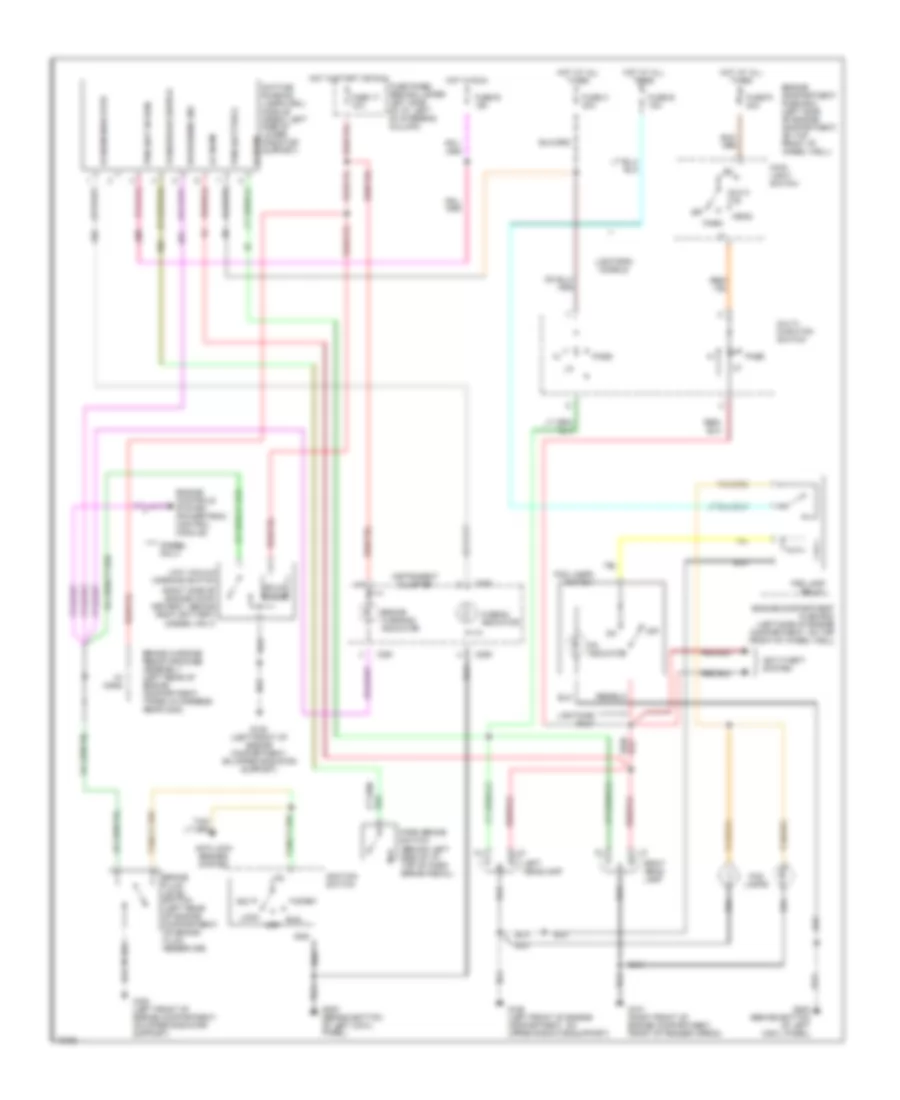
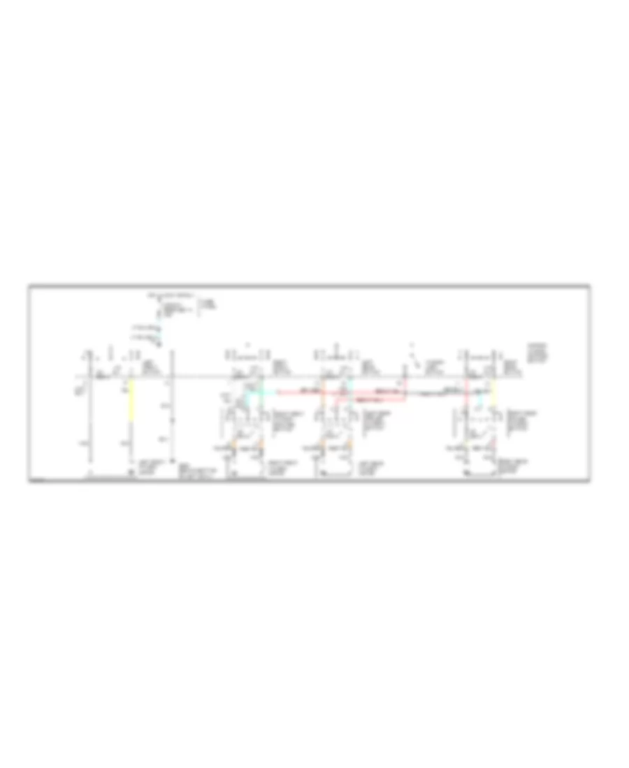
EXTERIOR LIGHTS
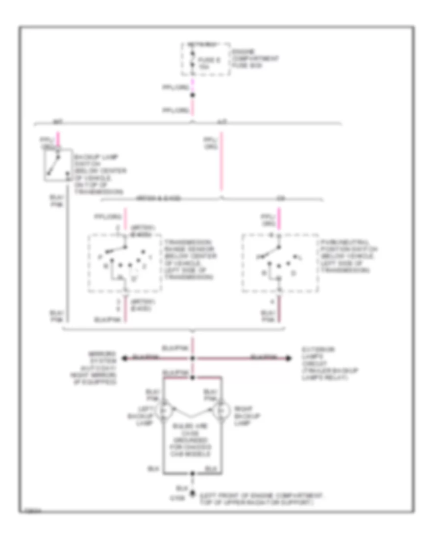
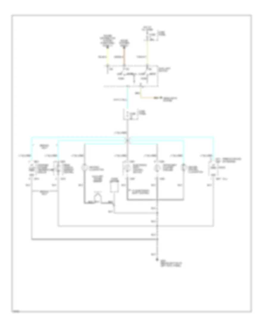
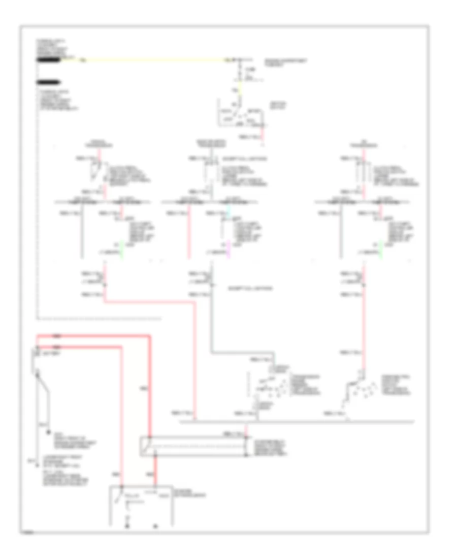
Back-up Lamps Wiring Diagram for Ford Cab & Chassis F350 1995
List of elements for Back-up Lamps Wiring Diagram for Ford Cab & Chassis F350 1995:
- (4r70w) (e4od)
- (left front of engine compartment, top of upper radiator support)
- 4r70w & e4od
- A/t
- Backup
- Backup lamp switch (below center of vehicle, on top of transmission)
- Bulbs are case grounded for chassis cab models
- Engine compartment fuse box
- Exterior lamps circuit (trailer backup lamps relay)
- Fuse e 15a
- G108
- Hot in run
- Lamp
- Left
- M/t
- Mirrors system (auto day/ night mirror) (if equipped)
- Park/neutral position switch (below vehicle, left side of transmission)
- Right backup lamp
- Transmission range sensor (below center of vehicle, left side of transmission)
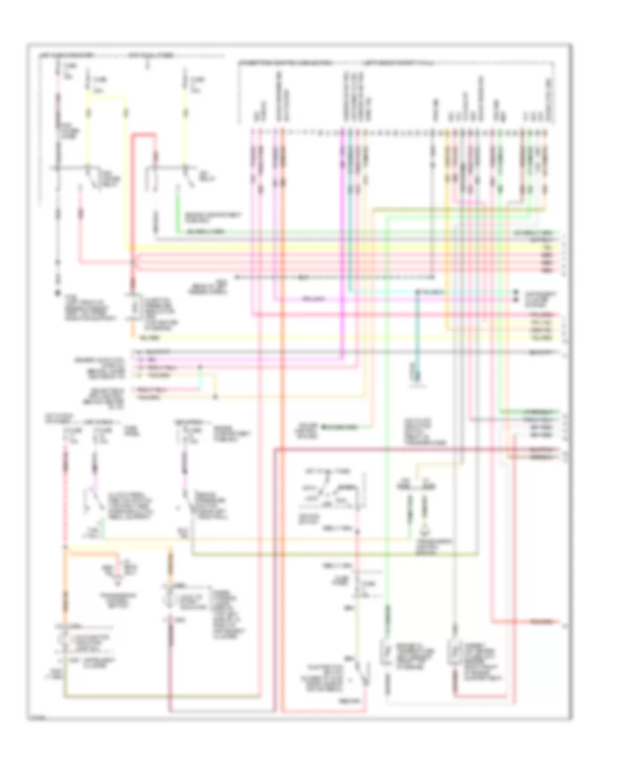
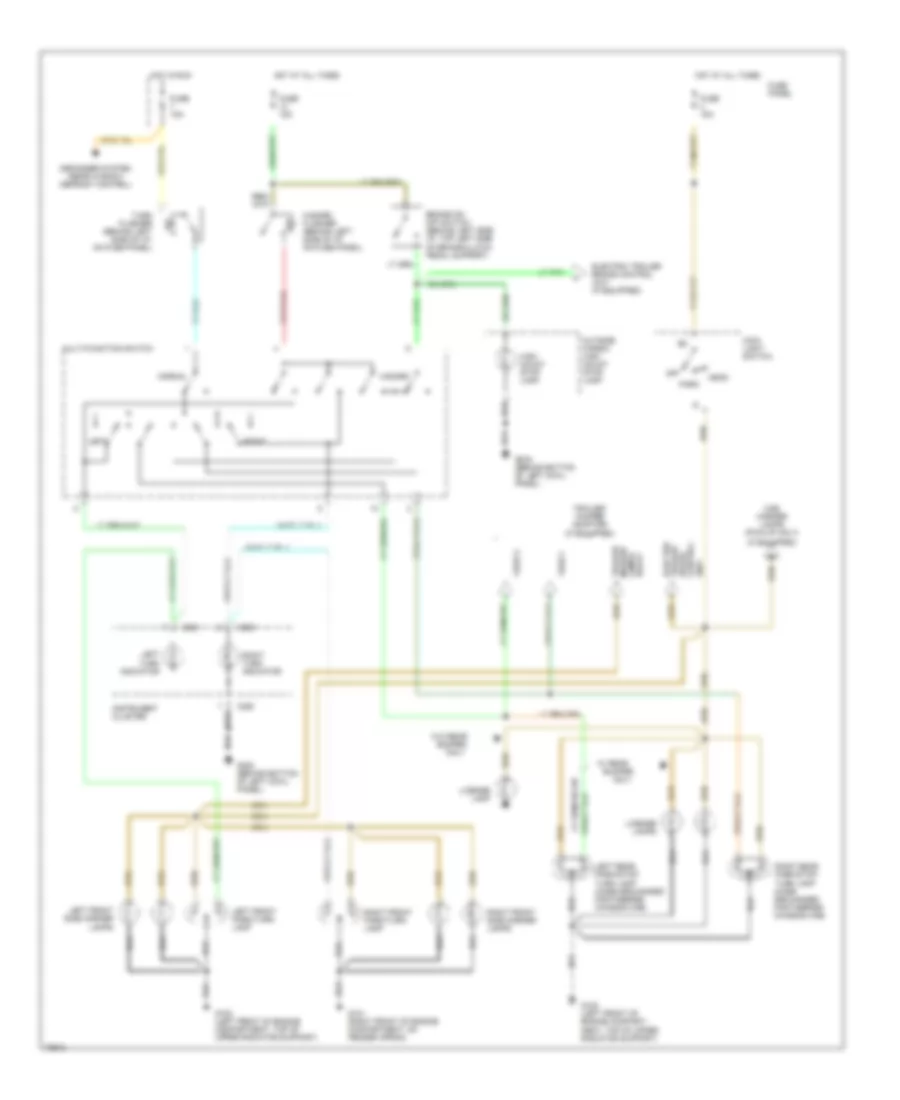
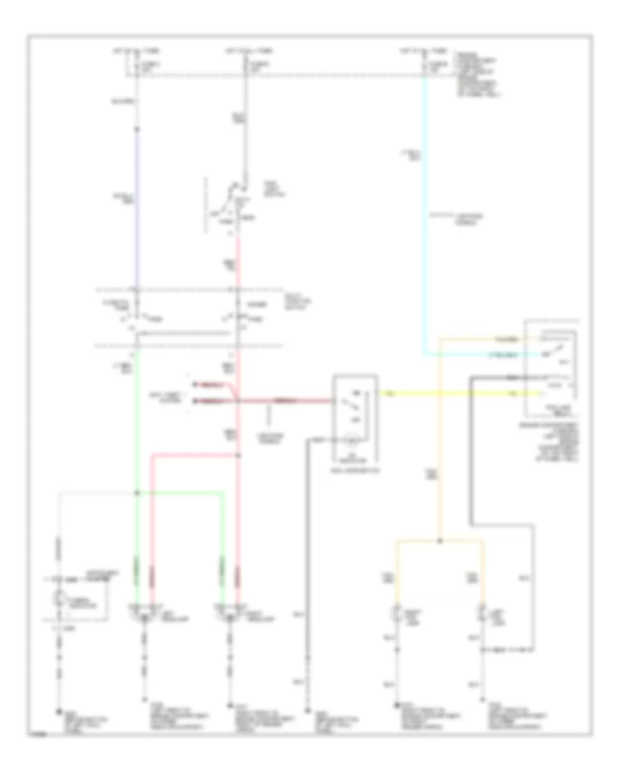
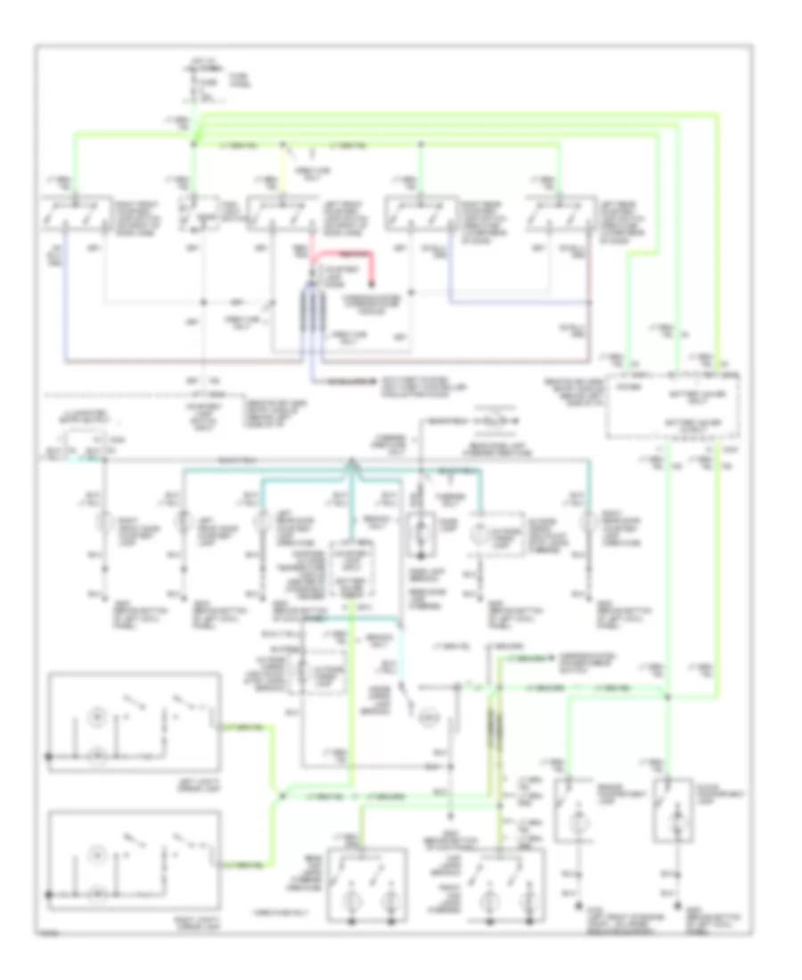
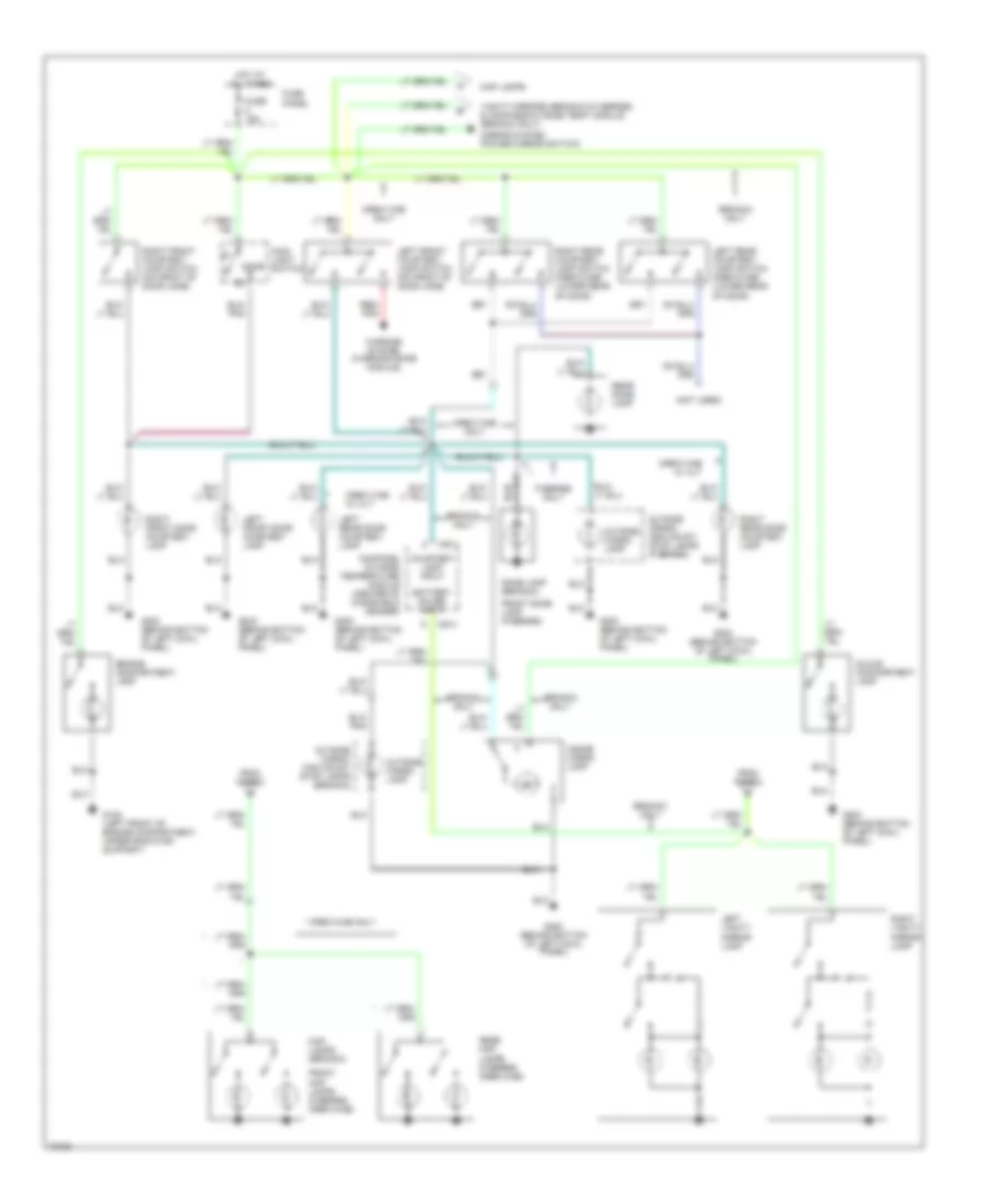
Exterior Lamps Wiring Diagram (1 of 2) for Ford Cab & Chassis F350 1995
List of elements for Exterior Lamps Wiring Diagram (1 of 2) for Ford Cab & Chassis F350 1995:
- (if equipped)
- Brake on/ off switch (behind left side i/p, top left side of brake/clutch pedal support)
- Bumper
- C250
- C251
- Cab marker lamps (pick-up only)
- Control brake trailer electric
- Defogger system (rear window defrost control)
- Electric trailer brake control unit (if equipped)
- Fuse 15a
- Fuse f
- Fuse g
- Fuse panel
- G101 (right front of engine compartment, on fender apron)
- G108 (left front of engine compart- ment, top of upper radiator support)
- G108 (left front of engine compartment, top of upper radiator support)
- G200 (behind bottom of left cowl panel)
- Hazard
- Hazard flasher (behind left side of i/p, on fuse panel)
- Head
- High mount stop lamp
- Hot at all times
- Hot in run
- Instrument cluster
- Left
- Left front park/turn lamp
- Left front side marker lamps
- Left rear park/stop/ turn lamp (case grounnded for f-series chassis cab)
- Left turn indicator
- License lamp
- License lamps
- Main light switch
- Multi-function switch
- Normal
- Off
- Only
- Outside cargo/ high mount stop lamp
- Park
- Right
- Right front park/turn lamp
- Right front side marker lamps
- Right rear park/stop/ turn lamp (case grounnded for f-series chassis cab)
- Right turn indicator
- Trailer marker lamps relay
- Trailer/ camper adapter (if equipped)
- Turn flasher (behind left side of i/p, on fuse panel)
- Unit
- W/ rear
- W/o rear
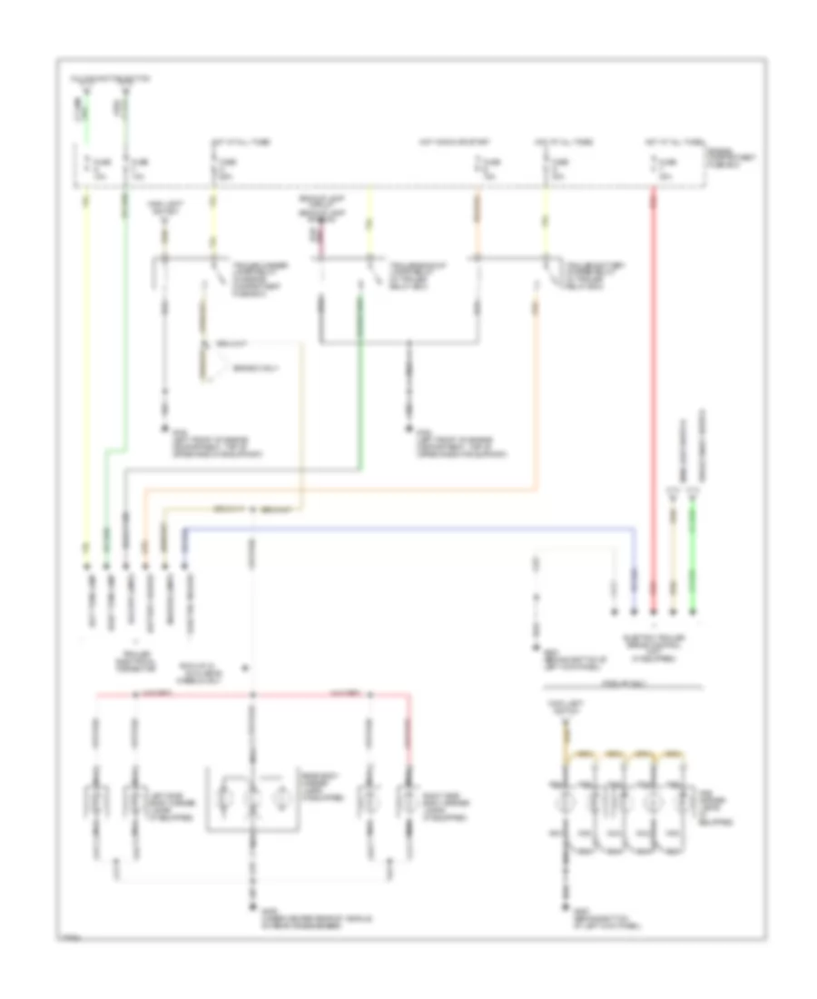
Exterior Lamps Wiring Diagram (2 of 2) for Ford Cab & Chassis F350 1995
List of elements for Exterior Lamps Wiring Diagram (2 of 2) for Ford Cab & Chassis F350 1995:
- Backup lamp circuit (backup lamp switch)
- Backup lamps
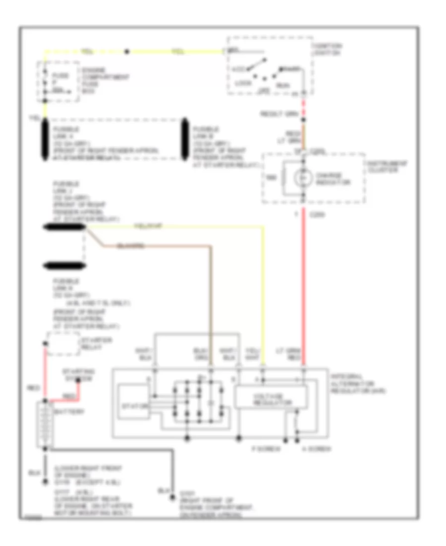
- Battery charge
- Brake on/off switch
- Bronco only
- Cab marker lamps (if equipped)
- Dual rear
- Electric brakes
- Electric trailer brake control unit (if equipped)
- Engine compartment fuse box
- Fuse d 25a
- Fuse e 15a
- Fuse f 10a
- Fuse g 10a
- Fuse q 30a
- Fuse t 30a
- G108 (left front of engine compartment, top of upper radiator support)
- G200 (behind bottom of left kick panel)
- G409 (under center rear of vehicle, on rear crossmember)
- Hot at all times
- Hot in run or start
- Left side body marker lamps (if equipped)
- Left turn lamp
- Main light switch
- Marker lamps
- Multi-function switch
- Nca
- Pick-up only
- Pick-up w/
- Rear body marker lamps (if equipped)
- Red
- Right side body marker lamps (if equipped)
- Right turn lamp
- Trailer backup lamps relay (in trailer relay box)
- Trailer battery charge relay (in trailer relay box)
- Trailer electrical connector
- Trailer marker lamps relay (in engine compartment fuse box)
- Wheels only
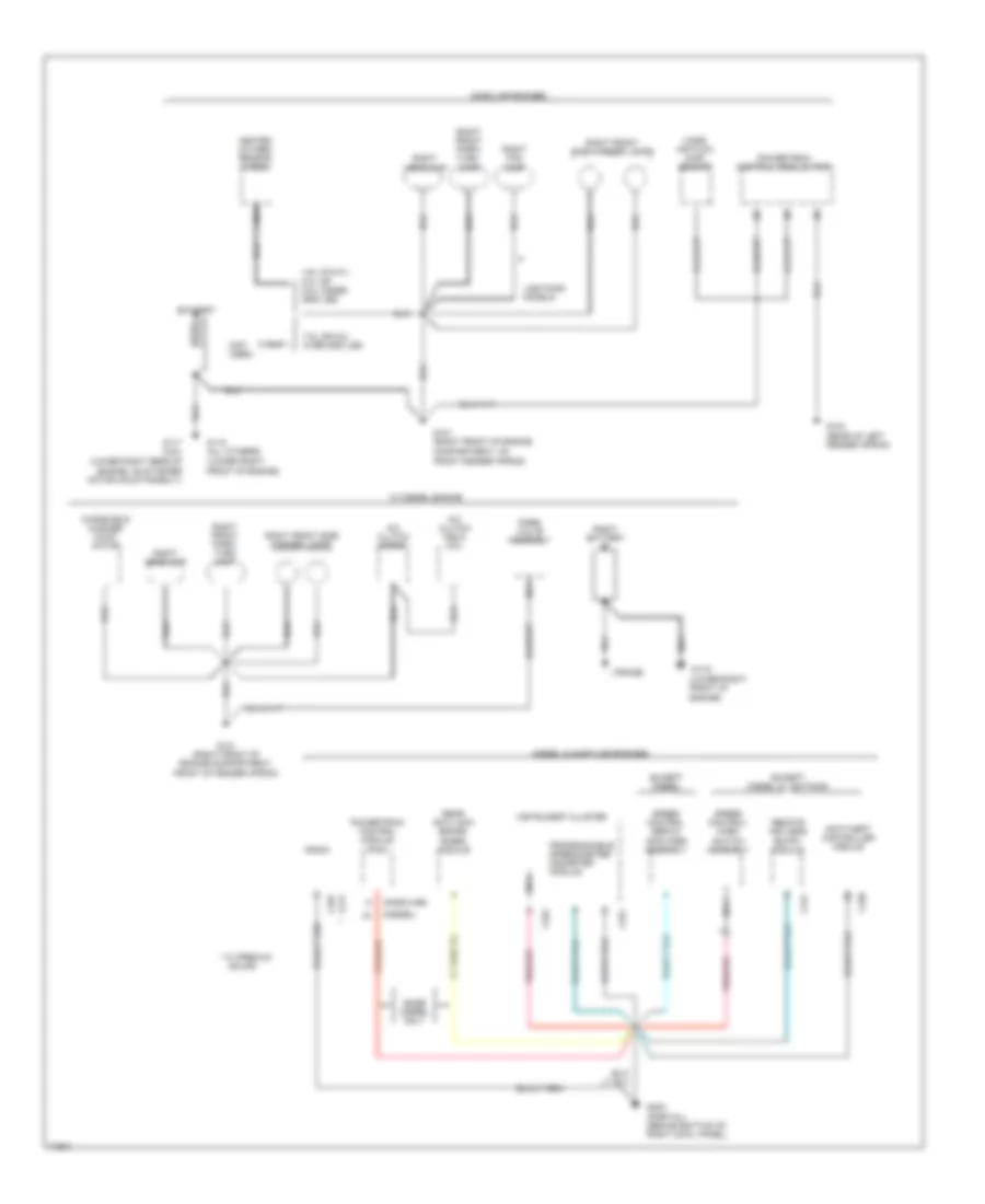
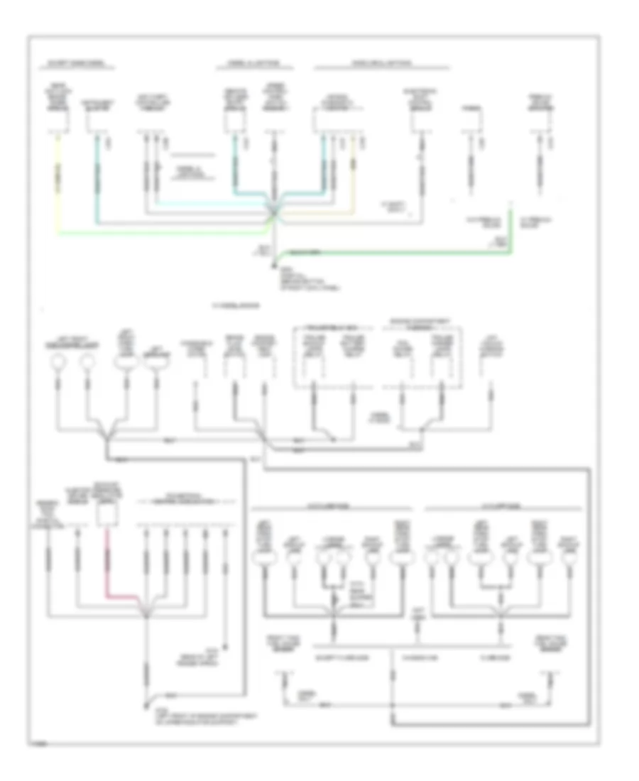
GROUND DISTRIBUTION
Ground Distribution Wiring Diagram (1 of 4) for Ford Cab & Chassis F350 1995
List of elements for Ground Distribution Wiring Diagram (1 of 4) for Ford Cab & Chassis F350 1995:
- (diesel)
- (frame)
- (gasoline)
- (lower right front of engine)
- (lower right rear of engine, on starter motor mounting bolt)
- (not used)
- * w/ premium
- 4.9l (calif.), 5.0l or 5.8l under 8500 lbs.
- 7.5l or 5.8l over 8500 lbs
- A/c clutch diode
- A/c clutch field coil
- Anti-theft controller module
- Base diesel only
- Battery
- C211
- C238
- C241
- C251
- C252
- C257
- Diesel & gasoline engines
- Except diesel
- Except diesel & lightning
- G101 (right front of engine compartment, front of fender apron)
- G101 (right front of engine compartment, on front fender apron)
- G104 (rear of left fender apron)
- G117 (4.9l)
- G119
- G119 (all others)
- G203 (partial) (behind bottom of right cowl panel)
- Gasoline engines
- Heated oxygen sensor (ho2s)
- Instrument cluster
- Lamp
- Lightning models
- Mass air flow (maf) sensor
- Nca
- Powertrain control module (pcm)
- Programmable speedometer/ odometer module
- Rabs valve assembly
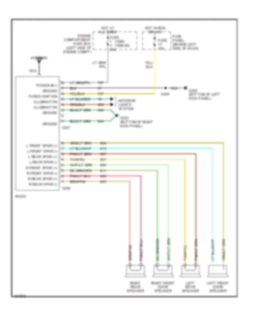
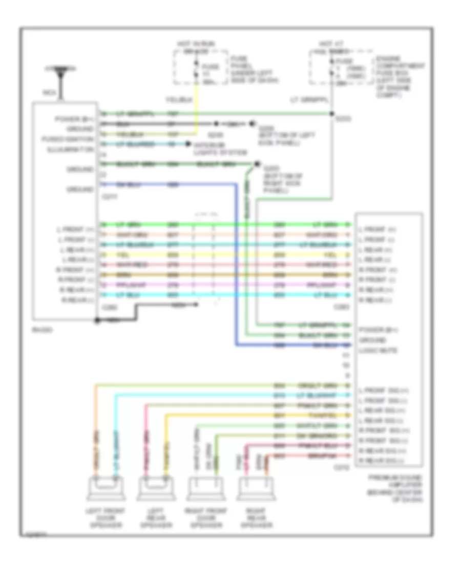
- Radio
- Rear anti-lock brake (rabs) module
- Remote keyless entry module
- Right battery
- Right fog lamp
- Right front park/ turn
- Right front park/ turn lamp
- Right front side marker lamps
- Right headlamp
- Sound
- Speed control servo/ amplifier assembly
- Speed control/ horn switch assembly
- W/ diesel engine
- Windshield washer pump motor
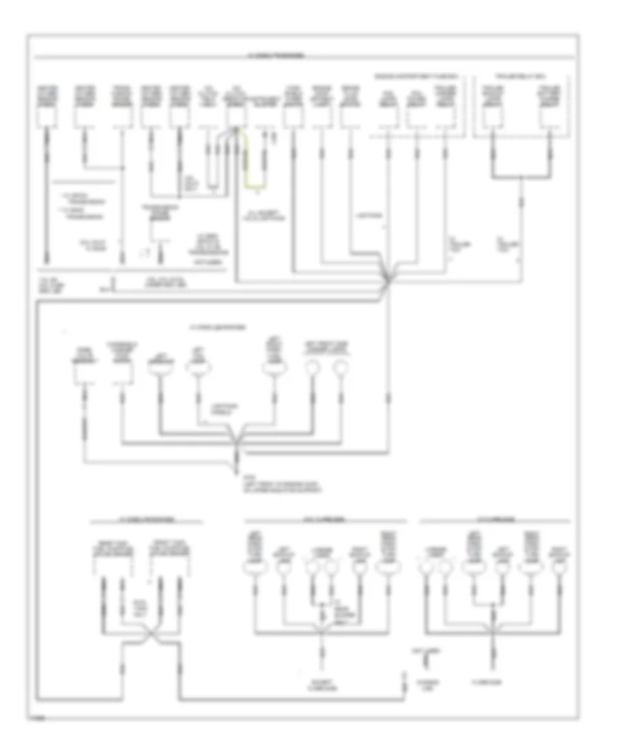
Ground Distribution Wiring Diagram (2 of 4) for Ford Cab & Chassis F350 1995
List of elements for Ground Distribution Wiring Diagram (2 of 4) for Ford Cab & Chassis F350 1995:
- w/o flare side
- (not
- (partial connector)
- (rear of left fender apron)
- Air bag diagnostic monitor
- Anti-theft controller module
- Brake fluid level switch
- Bumper
- C212
- C217
- C218
- C238
- C241
- C251
- C257
- Chassis cab
- Diesel only
- Diesel & lightning
- Diesel only
- Diesel w/ e4od
- Electronic shift control module
- Engine compart- ment lamp
- Engine compartment fuse box
- Except base diesel
- Except flare side
- Exhaust pressure regulator (epr)
- Flare side
- Front tank fuel gauge sender
- G104
- G108 (left front of engine compartment, on upper radiator support)
- G203 (partial) (behind bottom of right cowl panel)
- Gasoline & lightning
- Generic scan tool
- Injector driver module
- Instrument cluster
- Left backup lamp
- Left front park/ turn lamp
- Left front side marker lamps
- Left headlamp
- Left rear park/ stop/ turn lamp
- Left rear park/ stop/ turn lamp
- License lamps
- Low vacuum warning switch
- Nca
- Only
- Pcm power relay
- Powertrain control module (pcm)
- Premium sound amplifier
- Radio
- Rear
- Rear anti-lock brake (rabs) module
- Rear tank fuel gauge sender
- Remote keyless entry module
- Right backup lamp
- Right rear park/ stop/ turn lamp
- Speed control/ horn switch assembly
- Trailer backup lamps relay
- Trailer battery charge relay
- Trailer marker lamps relay
- Trailer relay box
- Used)
- W/ diesel engine
- W/ flare side
- W/ premium sound
- W/ shift- on-fly
- W/o premium sound
- Windshield wiper motor
- With
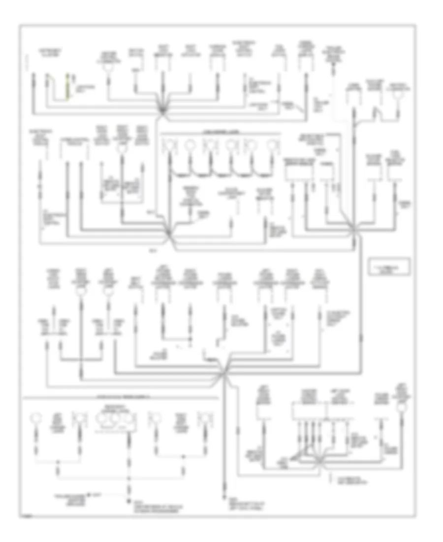
Ground Distribution Wiring Diagram (3 of 4) for Ford Cab & Chassis F350 1995
List of elements for Ground Distribution Wiring Diagram (3 of 4) for Ford Cab & Chassis F350 1995:
- (left front of engine comp., on upper radiator support)
- (not used)
- * **
- * w/ 4r70w
- ** w/ e4od
- 4.9l calif. only
- 4.9l, 5.0l & 5.8l under 8500 lbs)
- 5.8l calif. w/ e4od
- 7.5l or 5.8l over 8500 lbs.
- A/c clutch field coil
- A/c clutch resistor diode
- All except 4.9l & lightning
- Brake fluid level switch
- Bumper
- C250
- Cab
- Chassis
- Dual
- Engine comp- artment lamp
- Engine compartment fuse box
- Except
- Flare side
- Fog lamps relay
- Front tank fuel pump/fuel gauge sender
- G108
- Heated oxygen sensor (ho2s)
- Heated oxygen sensor (ho2s)
- Instrument cluster
- Left backup lamp
- Left fog lamp
- Left front park/ turn lamp
- Left front side marker lamps
- Left headlamp
- Left rear park/ stop/ turn lamp
- License lamps
- Lightning
- Lightning models
- Nca
- Only
- Pcm power relay
- Rabs valve assembly
- Rear
- Rear tank fuel pump/fuel gauge sender
- Right backup lamp
- Right rear park/ stop/ turn lamp
- Tank
- Trailer backup lamps relay
- Trailer battery charge relay
- Trailer relay box
- Trailer/ marker lamps relay
- Trans- mission range sensor
- Transmission
- Transmission range sensor
- W/ flare side
- W/ gasoline engines
- W/ m5r2, 4r7ow & 4.9l w/ c6 transmissions
- W/ trailer tow
- W/o flare side
- Wind- shield wiper motor
- Windshield washer pump motor
Ground Distribution Wiring Diagram (4 of 4) for Ford Cab & Chassis F350 1995
List of elements for Ground Distribution Wiring Diagram (4 of 4) for Ford Cab & Chassis F350 1995:
- (behind bottom of left cowl panel)
- (center rear of vehicle, on rear crossmember)
- ** w/ premium
- Ashtray illumination
- Auxiliary power socket
- Blower motor resistor
- Blower motor switch
- C211
- C240
- C250
- C257
- Cab marker lamps
- Captain chairs only
- Cargo/ high mount stop lamps
- Cigar lighter
- Crew cab w/ xlt
- Crew cab w/o xlt
- Day/ night mirror autolamp sensor
- Diesel only
- Diesel warning lamps display
- Electronic shift control module
- Electronic shift control switch
- F-350 w/ dual rear wheels
- Fog lamps switch
- Fuel tank selector switch
- G200
- G415
- Generic scan tool (partial connector)
- Glove compartment lamp
- Gnd
- Heater control illumination
- Ignition switch
- Instrument cluster
- Keyless entry
- Left door lock control switch
- Left front door courtesy lamp
- Left front door disarm switch
- Left power lumbar compressor motor
- Left power lumbar/ bolster compressor motor
- Left rear door courtesy lamp
- Left side body marker lamps
- Lightning only
- Master window control switch
- Nca
- Power lumbar compressor motor
- Power mirror switch
- Radio
- Rear body marker lamps
- Remote keyless entry module
- Right door lock control switch
- Right front door courtesy lamp
- Right front door disarm switch
- Right power lumbar compressor motor
- Right power lumbar/ compressor motor
- Right rear door courtesy lamp
- Right side body marker lamps
- Seat belt switch
- Selectable rpm control (partial)
- Shift lock actuator
- Shift lock resistor
- Sound
- Trailer electronic brake control
- Trailer/camper adapter (grounds)
- W/ electric day/night mirror only
- W/ electronic shift control
- W/ power bolster
- W/ power lumbar only
- W/ power mirror
- W/ remote keyless entry
- W/ trailer tow only
- W/o crew cab
- W/o power bolster
- W/o remote *
- W/o remote keyless entry
- Warning chime module
- Wiper control module
HEADLIGHTS
Headlamps Wiring Diagram, with DRL for Ford Cab & Chassis F350 1995
List of elements for Headlamps Wiring Diagram, with DRL for Ford Cab & Chassis F350 1995:
- (behind left side of i/p, top of park brake pedal)
- (diesel only)
- (right side of engine comp- artment, behind right battery)
- 1k ohms
- 22.5 a c.b.
- Acc
- Anti-lock brakes system
- Anti-theft system
- Bk warning ind
- Brake fluid level switch (left rear of engine compartment, on brake fluid reservoir)
- Brake warning indicator
- Brake warning resistor/diode assembly (left rear of engine compartment, taped in harness near c202)
- C250
- C251
- Daytime running lamps (drl) module (front left side of lower radiator support)
- Engine compartment fuse box (left side of engine compartment, on top front of wheel well)
- Engine controls system (powertrain control module)
- Fog lamp relay
- Fog lamps
- Fog lamps switch
- Fuse 17 10a
- Fuse b 15a
- Fuse c 30a
- Fuse e 15a
- Fuse panel (behind lower left side of i/p, left of steering column)
- Fuse r 40a
- G101 (right front of engine compartment, front of fender apron)
- G108 (left front of engine compartment, on upper radiator support)
- G200 (behind bottom of left cowl panel)
- Gnd
- Head
- Hi beam
- Hi beam indicator
- Hot at all times
- Hot in run
- Hot in start or run
- Ignition switch
- Instrument cluster
- Left headlamp
- Lightning models
- Lightning only
- Lo beam
- Lock
- Low vacuum warning switch
- Main light switch
- Multi- function switch
- Off
- On indicator
- Park
- Park brake switch
- Park/brake switch
- Pass
- Pwr (battery)
- Pwr (hot in run)
- Red
- Right head- lamp
- Run
- Solid state
- Start
Headlamps Wiring Diagram, without DRL for Ford Cab & Chassis F350 1995
List of elements for Headlamps Wiring Diagram, without DRL for Ford Cab & Chassis F350 1995:
- 22.5 a c.b.
- Anti- theft system
- C250
- Dimmer
- Engine compartment fuse box (left side of engine compartment, on top front of wheel well)
- Flash-to- pass
- Fog lamp relay
- Fog lamps switch
- Fuse b 15a
- Fuse c 30a
- Fuse r 40a
- G101 (right front of engine compartment, front of fender apron)
- G101 (right front of engine compartment, on front fender apron)
- G108 (left front of engine compartment, on upper radiator support)
- G200 (behind bottom of left cowl panel)
- Head
- Hi beam indicator
- Hot at all times
- Instrument cluster
- Left fog lamp
- Left headlamp
- Lightning models
- Main light switch
- Multi- function switch
- Off
- On indicator
- Park
- Pass
- Right fog lamp
- Right headlamp
HORN
Horn Wiring Diagram for Ford Cab & Chassis F350 1995
List of elements for Horn Wiring Diagram for Ford Cab & Chassis F350 1995:
- (bronco)
- (f pickup)
- (f pickup) (bronco)
- (near brake master cylinder)
- 30a
- Anti-theft controller module (center of i/p)
- Engine compartment fuse box
- Fuse c
- High pitch horn (right rear side of lower radiator support, below lamps)
- Horn enable output
- Horn relay
- Horn relay (engine compartment fuse box)
- Horn switch
- Hot at all times
- Low pitch horn (right rear side of lower radiator support, below lamps)
- Nca
- Remote keyless entry module (left side of i/p)
- Speed control servo/ amplifier assembly
- Speed control switch ground
- Speed control/ horn switch assembly
INSTRUMENT CLUSTER
Instrument Cluster Wiring Diagram (1 of 2) for Ford Cab & Chassis F350 1995
List of elements for Instrument Cluster Wiring Diagram (1 of 2) for Ford Cab & Chassis F350 1995:
- (behind bottom of left cowl panel)
- (behind bottom of right cowl panel)
- (behind lower center of i/p)
- (behind lower right side of i/p, below glove compt)
- (di diesel) (except di diesel)
- (left front of engine compt, on upper radiator support)
- (left side of engine compt,
- (left side of safety wall)
- (w/ tach) (w/o tach)
- 20 ohms
- 4x4 ind.
- 500 ohms
- A10
- A11
- A12
- A13
- A14
- A5 b6
- Acc
- Air bag ind.
- Amplifier assembly
- Anti-lock brake ind.
- Anti-theft ind.
- B10
- B12
- B13
- Bat
- Brake warning ind.
- Charge ind.
- Check engine ind.
- Chime module
- Conn a
- Conn b
- Conn c
- Control
- Coolant temp.
- Coolant temp. gauge
- Diesel engines only
- Diesel warning lamps display
- Enable psom programming connector
- Engine speed
- Engine warning ind.
- Except diesel
- Except lightning
- Exterior lights system (multi-function switch)
- Fasten seat belt ind.
- Fuel gauge
- Fuel level
- Fuel water switch (right side of engine, on bottom of fuel filter/heater)
- Fuse 10a
- Fuse 15a
- Fuse 4a
- Fuse panel
- G108
- G200
- G203
- Gasoline only
- Generator/ voltage regulator
- Gnd
- Headlights system (multi-function switch)
- Hi beam ind.
- Hot at all times
- Hot in run
- Hot in run or start
- Hot w/ light sw in head or park
- Ign
- Ign (run)
- Ignition switch
- Illum.
- Illum. lamps
- Instrument cluster
- Left turn ind.
- Lightning only
- Lock
- Low range ind.
- Mechanical shift only
- Module
- Near brake master cylinder)
- Off
- Oil press.
- Oil press. gauge
- Overheat warning switch (left front of engine)
- Plugged fuel filter ind.
- Plugged fuel filter switch (right side of engine, in fuel filter/heater housing)
- Powertrain
- Programmable speedometer/ odometer module
- Red
- Red/pnk
- Right turn ind.
- Run
- Solid state
- Speed control servo/
- Start
- Tacho- meter
- Test
- Volt- meter
- Vss input
- Vss output
- Vss return
- W/ tach
- W/o tach
- Wait-to- start ind.
- Warning
- Water-in- fuel ind.
- Water-in- fuel sensor (right side of engine, near fuel filter)
Instrument Cluster Wiring Diagram (2 of 2) for Ford Cab & Chassis F350 1995
List of elements for Instrument Cluster Wiring Diagram (2 of 2) for Ford Cab & Chassis F350 1995:
- (4.9l-left front of engine, forward of distributor)
- (5.0l & 5.8l- (left rear of engine, near intake manifold)
- (behind left side of i/p)
- (behind right side of i/p, behind glove compt)
- (below right center of
- (below right rear of
- (left front of engine compt, on upper radiator support)
- (left rear of engine
- (left rear of engine compt,
- (w/ drl)
- (w/o drl)
- 4x2
- 4x4
- 4x4 hi/low indicator switch (below vehicle, on front of transfer case)
- Air bag diagnostic monitor (behind left side of i/p)
- Anti-theft controller
- Brake fluid level switch (left rear of engine compt, on brake fluid reservoir)
- Brake warning resistor/diode assembly (left rear of engine compt, taped in harness)
- Compt, on bracket)
- Data link connector
- Daytime running lamps module (front left side of lower radiator support)
- Diesel
- Diesel only
- Diesel w/ tach
- Elect. shift
- Electronic shift control module (behind right cowl panel)
- Electronic shift control switch
- Electronic shift only
- Engine coolant temperature sender (4.9l-right side of engine) (except 4.9l-top left front of engine)
- Engine oil pressure switch (4.9l-lower left rear of engine, near oil filter) (5.0l & 5.8l-lower left front of engine, near oil filter) (7.3l & 7.5l-top center rear of engine)
- Engines only
- Front
- Front tank fuel gauge sender
- Front tank fuel pump/
- Fuel gauge sender
- Fuel tank selector switch
- Fuel tank selector valve (under left center of vehicle, on left frame rail)
- Fuse 6 15a
- Fuse panel: i/p
- G108
- G200 (bottom of left cowl panel)
- Gas
- Gas &
- Hot in acc or run
- Ignition coil
- Ignition control module (left rear of engine compt, on fender apron)
- Lightning
- Link connector
- Low
- Low vacuum warning switch (right side of engine compt, behind right battery)
- Mech. shift
- Module
- Nca
- On bracket)
- Park brake switch
- Power- train control module (left side of safety wall)
- Powertrain control module (left side of safety wall)
- Powertrain control module (left side of safety wall)
- Rabs data
- Rear
- Rear anti-lock brake module
- Rear axle speed sensor (on axle assembly)
- Rear tank fuel gauge sender
- Rear tank fuel pump/
- Red
- Red/
- Red/ pnk
- Red/pnk
- Solid state
- Vehicle, in front fuel tank)
- Vehicle, in rear fuel tank)
- W/ drl
- W/o drl
INTERIOR LIGHTS
Courtesy Lamps Wiring Diagram, with Remote/Keyless Entry for Ford Cab & Chassis F350 1995
List of elements for Courtesy Lamps Wiring Diagram, with Remote/Keyless Entry for Ford Cab & Chassis F350 1995:
- * crew-cab only
- Anti-theft system (anti-theft controller module pin#14/c238)
- Battery saver input
- Battery saver output
- Bronco only
- C240
- C241
- C242
- C914
- Compass/ outside temperature module (center of windshield header)
- Courtesy lamp diode
- Courtesy lamp input
- Courtesy lamp switch input
- Crew cab only
- Dome
- Dome lamp
- Dome lamp (bronco)
- Engine compartment lamp
- F-series crew-cab only
- F-series only
- Front map lamps (f-series)
- Fuse 15a
- Fuse panel
- G108 (left front of engine compt., on upper radiator support)
- G200 (behind bottom of cowl panel)
- G200 (behind bottom of kick panel)
- G200 (behind bottom of left cowl panel)
- Glove compartment lamp
- Hot at all times
- Illuminated entry output
- Inside cargo lamp (bronco)
- Left front courtesy lamp switch (on front of door jamb)
- Left front door courtesy lamp
- Left rear courtesy lamp switch (crew-cab) (lower rear of door)
- Left rear door courtesy lamp (crew-cab)
- Left vanity mirror lamp
- Main light switch
- Map lamps (bronco)
- Mirrors system (power mirror switch)
- Outside cargo lamp
- Outside cargo/ high mount stop lamps (bronco)
- Outside cargo/ high mount stop lamps (f-series)
- Power
- Rear dome lamp (f-series crew-cab)
- Rear dome lamp (f-series)
- Rear map lamps (f-series crew-cab)
- Red/ pnk
- Red/pnk
- Remote keyless entry module (behind left side of i/p)
- Right front courtesy lamp switch (on front of door jamb)
- Right front door courtesy lamp
- Right rear courtesy lamp switch (crew-cab) (lower rear of door)
- Right rear door courtesy lamp (crew-cab)
- Right vanity mirror lamp
- Warning system (warning chime module)
Courtesy Lamps Wiring Diagram, without Remote/Keyless Entry for Ford Cab & Chassis F350 1995
List of elements for Courtesy Lamps Wiring Diagram, without Remote/Keyless Entry for Ford Cab & Chassis F350 1995:
- (not used)
- * crew-cab only
- Battery saver input
- Bronco only
- C914
- Compass/ outside temperature module (center of windshield header)
- Courtesy lamp input
- Crew cab only
- Crew cab w/ xlt
- Dome
- Dome lamp (bronco)
- Engine compartment lamp
- F-series only
- From fuse 8
- Front dome lamp (f-series)
- Front map lamps (f-series crew-cab)
- Fuse 15a
- Fuse panel
- G108 (left front of engine compartment, upper radiator support)
- G200 (behind bottom of left cowl panel)
- Glove compartment lamp
- Hot at all times
- Inside cargo lamp
- Left front courtesy lamp switch (on front of door jamb)
- Left front door courtesy lamp
- Left rear courtesy lamp switch (crew-cab) (lower rear of door)
- Left rear door courtesy lamp
- Left vanity mirror lamp
- Main light switch
- Map lamps
- Map lamps (bronco)
- Mirror system (power mirror switch)
- Outside cargo lamp
- Outside cargo/ high mount stop lamps (bronco)
- Outside cargo/ high mount stop lamps (f-series)
- Rear dome lamp
- Rear map lamps (f-series crew-cab)
- Red/ pnk
- Right front courtesy lamp switch (on front of door jamb)
- Right front door courtesy lamp
- Right rear courtesy lamp switch (crew-cab) (lower rear of door)
- Right rear door courtesy lamp
- Right vanity mirror lamp
- Vanity mirrors (bronco & f-series) & compass/outside temp. module (bronco only)
- Warning system (warning chime module)
Instrument Illumination Wiring Diagram for Ford Cab & Chassis F350 1995
List of elements for Instrument Illumination Wiring Diagram for Ford Cab & Chassis F350 1995:
- (all)
- (premium sound)
- (standard)
- Ashtray illumination
- Auxiliary power socket
- Bronco only
- C211
- C250
- C257
- C267
- C278
- C914
- Cigar lighter
- Compass/ outside temperature module
- Electronic shift control switch
- Fuse 15a
- Fuse 4a
- Fuse panel
- G200 (behind bottom of left cowl panel)
- Gnd
- Head
- Headlights system
- Heater control illumination
- Hot at all times
- I/p feed
- I/p illum feed
- Ign
- Instrument cluster (5 bulbs)
- Main light switch
- Off
- Park
- Power distribution system (fuse panel) (fuse 11)
- Radio
- Rear window defrost control
- Sound systems (radio)
- W/ electronic shift control
POWER DISTRIBUTION
Power Distribution Wiring Diagram (1 of 3) for Ford Cab & Chassis F350 1995
List of elements for Power Distribution Wiring Diagram (1 of 3) for Ford Cab & Chassis F350 1995:
- (behind bottom of left cowl panel)
- (crew cab)
- (diesel)
- (gasoline)
- * 4.9l & 7.5l
- ** diesel only
- 300a
- A/c-heater control assembly
- Acc
- Air bag diagnostic monitor
- Anti-theft controller module
- C1029
- C153
- C154
- C165
- C217
- C237
- C241
- C252
- Circuit breaker 14 20a
- Clutch pedal position switch
- Day/night mirror autolamp sensor
- Diesel only
- Diesel with 200a generator
- Electronic shift control module
- Engine compartment fuse box
- Engine compartment fuse box (fuse e)
- Engine compartment fuse box (fuse u)
- Fuel tank selector switch
- Fuse 10a
- Fuse 15a
- Fuse 20a
- Fuse 30a
- Fuse d 25a
- Fuse j 20a
- Fuse link l
- Fuse n 50a
- Fuse p 50a
- Fuse panel
- Fuse q 30a
- G200
- Gasoline only
- Generator/ voltage regulator
- Glow plug relay
- Gnd
- Heater control assembly
- Heater or a/c-heater control module
- Ign
- Ignition switch
- Instrument cluster
- Instrument cluster system
- Left battery (diesel only)
- Lock
- Main light switch
- Master window control switch
- Mega fuse (right front of engine)
- Off
- Programable speedometer/ odometer module
- Radio
- Rear anti-lock brake (rabs) module
- Red
- Remote keyless entry module
- Right battery
- Right window control switch
- Run
- Selectable rpm control (partial connector)
- Shift lock actuator
- Sta
- Start
- Starter relay
- Starter solenoid
- Starting/charging system (clutch pedal position switch)
- Trailer backup lamps relay
- Trailer battery charge relay
- Trailer relay box
- Trailer/ marker lamps relay
- Turn flasher
- W/ air bag only
- W/ anti- theft only
- W/ remote keyless entry only
- W/ shift- on- fly
- W/ trailer tow only
- W/o crew cab only
- Warning system
- Winshield wiper motor
- Wiper control module
- With a/c
- Without a/c
Power Distribution Wiring Diagram (2 of 3) for Ford Cab & Chassis F350 1995
List of elements for Power Distribution Wiring Diagram (2 of 3) for Ford Cab & Chassis F350 1995:
- (4r70w)
- (diesel only)
- (e4od)
- * diesel
- 4.9l (49 states), 5.0l or 5.8l under 8500 lbs & lightning
- 4.9l calif. not used
- 5.8l over 8500 lbs & 7.5l
- Backup lamp switch
- Brake pressure switch
- Brake warning resistor/ diode assembly
- C250
- C251
- Daytime running lamp (drl) module (w/ drl only)
- Diesel only
- Diesel warning lamps display
- Distributor
- Electronic shift control switch
- Engine comparment fuse box
- Engine compartment fuse box
- Fog lamp relay (lightning only)
- From ignition switch
- Fuel line heater
- Fuel pump relay
- Fuel water switch
- Fuse 10a
- Fuse 3a
- Fuse 4a
- Fuse b 15a
- Fuse e 15a
- Fuse h 30a
- Fuse i 20a
- Fuse o 20a
- Fuse panel
- Fuse q 30a
- Fuse u 20a
- Fuse u 30a
- Gasoline only
- Glow plug relay
- Heated oxygen sensor (ho2s)
- Idle position switch
- Ignition coil
- Ignition control module
- Injector driver module (idm) relay
- Instrument cluster
- Interior lights system
- Interior lights system (main light switch)
- Low vacuum warning switch
- Nca
- Only
- Park/neutral position switch
- Pcm power diode
- Pcm power relay
- Powertrain control module
- Rabs ii f-series only
- Radio capacitor
- Red/
- Speed control servo/amplifier assembly
- Trailer battery charge relay
- Trailer relay box
- Trans- mission control module
- Transmission range sensor
- W/ c6 transmission
- W/ diesel engine
- W/ e40d 0r 4r70w transmission
- W/ gasoline engine
- W/ manual transmission
- Warning chime module
- With electronic shift only
Power Distribution Wiring Diagram (3 of 3) for Ford Cab & Chassis F350 1995
List of elements for Power Distribution Wiring Diagram (3 of 3) for Ford Cab & Chassis F350 1995:
- (behind bottom of left cowl panel)
- (w/ crew cab)
- (w/o crew cab)
- Air bag diagnostic monitor
- Anti-theft controller module
- Auxiliary power socket
- Brake on/off (boo) switch
- Brake pressure switch
- C217
- C237
- C240
- C241
- C252
- Circuit breaker 12 20a
- Crew cab only
- Daytime running lamp (drl) module
- Electronic shift control module
- Engine compart- ment lamp
- Engine compartment fuse box
- Exterior lights system (multi-function switch)
- Front map lamps
- Fuse 10a
- Fuse 15a
- Fuse 25a
- Fuse a 20a
- Fuse block
- Fuse c 30a
- Fuse f 10a
- Fuse g 10a
- Fuse l 50a
- Fuse panel
- Fuse r 40a
- Fuse s 50a
- Fuse t 30a
- G200
- Gasoline only
- Generic scan tool (partial connector)
- Glove compart- ment lamp
- Hazard flasher
- Horn relay
- Instrument cluster
- Left door lock control switch
- Left front courtesy lamp switch
- Left power lumbar switch
- Left power lumbar/ bolster switch
- Left rear courtesy lamp switch
- Left vanity mirror lamp
- Lighter
- Main light switch
- Multi- function switch
- Nca
- Power mirror switch
- Premium sound ampli- fier
- Program- mable speedo- meter/ odometer module
- Radio
- Rear anti- lock brake (rabs) module
- Red
- Remote keyless entry module
- Remote keyless entry module
- Right door lock control switch
- Right front courtesy lamp switch
- Right power lumbar switch
- Right rear courtesy lamp switch
- Right vanity mirror lamp
- To trailer electronic brake control
- To trailer left turn lamps
- To trailer right turn lamps
- Trailer provision
- Trailer provisions
- W/ air bag only
- W/ anti- theft system only
- W/ captain's chair
- W/ cloth bench
- W/ power bolster
- W/ power lumbar seats
- W/ premium sound only
- W/ remote keyless entry
- W/ remote keyless entry only
- W/o keyless entry
- W/o remote keyless entry
- With vanity mirrors
POWER DOOR LOCKS
Keyless Entry Wiring Diagram for Ford Cab & Chassis F350 1995
List of elements for Keyless Entry Wiring Diagram for Ford Cab & Chassis F350 1995:
- (behind bottom of left cowl panel)
- (behind bottom of right cowl panel)
- Antenna
- Anti- theft system
- Anti-theft system (anti-theft module)
- Battery saver input
- Battery saver output
- C240
- C241
- C242
- Circuit breaker 12 20a
- Courtesy lamps output
- Crtsy lamp sw input
- Door ajar switch and indicator
- Exterior lights system
- Fuse 15a
- Fuse panel
- G200
- G200 (behind bottom of left cowl panel)
- G203
- Ground
- Horn relay
- Horns system
- Hot at all times
- Hot in accy or run
- Ignition switch input
- Interior lights system
- Interior lights system (door courtesy lamp switches)
- Left door lock control switch
- Left front door lock motor
- Left rear door lock motor
- Lock doors output
- Lock input
- Lock unlock
- Park lamp input
- Park lamps output
- Power
- Program a
- Program b
- Remote keyless entry module (behind left side of i/p)
- Right door lock control switch
- Right front door lock motor
- Right rear door lock motor
- Rke program connector (behind left side of i/p)
- Unlock doors output
- Unlock driver's door
- Unlock input
- W/ crew cab
Power Door Locks Wiring Diagram, with Crew Cab for Ford Cab & Chassis F350 1995
List of elements for Power Door Locks Wiring Diagram, with Crew Cab for Ford Cab & Chassis F350 1995:
- 20a
- Circuit breaker 12
- Fuse panel
- G200 (behind bottom of left kick panel)
- Hot at all times
- Left door lock control switch
- Left front door lock motor
- Left rear door lock motor
- Lock
- Pnk/
- Right door lock control switch
- Right front door lock motor
- Right rear door lock motor
- Unlock
Power Door Locks Wiring Diagram, without Crew Cab for Ford Cab & Chassis F350 1995
List of elements for Power Door Locks Wiring Diagram, without Crew Cab for Ford Cab & Chassis F350 1995:
- 20a
- Circuit breaker 12
- Fuse panel
- G200 (behind bottom of left cowl panel)
- Hot at all times
- Left door lock control switch
- Left front door lock motor
- Lock
- Pnk/
- Right door lock control switch
- Right front door lock motor
- Unlock
POWER MIRRORS
Power Mirror Wiring Diagram for Ford Cab & Chassis F350 1995
List of elements for Power Mirror Wiring Diagram for Ford Cab & Chassis F350 1995:
- (behind bottom of left kick panel)
- A/t
- Backup lamp switch (left side of transmission)
- Day/night mirror autolamp sensor (in center of windshield header)
- Direct- tional switch
- Engine compartment fuse box
- Exterior lights system (backup lamps)
- Fuse 10a
- Fuse 15a
- Fuse e 15a
- Fuse panel
- G200
- G200 (behind bottom of left kick panel)
- Hot at all times
- Hot in run
- L/r motor
- Left power mirror nca
- Left/ right switch
- M/t
- Nca
- Park/ neutral position switch (left side of transmission)
- Power mirror switch
- Red
- Right power mirror nca
- Up/dn motor
POWER SEATS
Lumbar Wiring Diagram, with Captain's Chairs for Ford Cab & Chassis F350 1995
List of elements for Lumbar Wiring Diagram, with Captain's Chairs for Ford Cab & Chassis F350 1995:
- Circuit breaker 12 20a
- Fuse panel
- G200 (behind bottom of left kick panel)
- Hot at all times
- Left power lumbar compressor motor
- Left power lumbar switch
- Nca
- Power door locks system
- Right power lumbar compressor motor
- Right power lumbar switch
Lumbar Wiring Diagram, with Cloth Bench for Ford Cab & Chassis F350 1995
List of elements for Lumbar Wiring Diagram, with Cloth Bench for Ford Cab & Chassis F350 1995:
- Circuit breaker 12 20a
- Fuse panel
- G200 (behind bottom of left kick panel)
- Hot at all times
- Left power lumbar switch
- Nca
- Power lumbar compressor motor
- Right power lumbar switch
Lumbar/Bolster Wiring Diagram, with Captain's Chairs for Ford Cab & Chassis F350 1995
List of elements for Lumbar/Bolster Wiring Diagram, with Captain's Chairs for Ford Cab & Chassis F350 1995:
- Circuit breaker 12 20a
- Fuse panel
- G200 (behind bottom of left kick panel)
- Hot at all times
- Left power lumbar/bolster compressor motor
- Left power lumbar/bolster switch
- Nca
- Right power lumbar compressor motor
- Right power lumbar switch
POWER WINDOWS
Power Windows Wiring Diagram, Crew Cab for Ford Cab & Chassis F350 1995
List of elements for Power Windows Wiring Diagram, Crew Cab for Ford Cab & Chassis F350 1995:
- Circuit breaker 14 20a
- Control switch
- Fuse panel
- G200 (behind bottom of left cowl)
- Hot in accy or run
- Left front switch
- Left front window motor
- Left rear power window switch
- Left rear switch
- Left rear window motor
- Master window control switch
- Nca
- Right front switch
- Right front window
- Right front window motor
- Right rear power window switch
- Right rear switch
- Right rear window motor
- Tan/
- Up down
- Window lock switch
Power Windows Wiring Diagram, Except Crew Cab for Ford Cab & Chassis F350 1995
List of elements for Power Windows Wiring Diagram, Except Crew Cab for Ford Cab & Chassis F350 1995:
- (behind bottom of
- 20a
- Breaker 14
- Circuit
- Fuse panel
- G200
- Hot in acc or run
- Left cowl)
- Left front window motor
- Left window switch
- Master window control switch
- Nca
- Red/
- Right front window motor
- Right window control switch
- Right window switch
- Tan/
- Up down
RADIO
Base Radio for Ford Cab & Chassis F350 1995
List of elements for Base Radio for Ford Cab & Chassis F350 1995:
- (1996) (1994-95)
- Antenna
- C257
- C258
- Engine compartment fuse box (left side of engine compt)
- Fuse 15a
- Fuse a 20a
- Fuse panel (behind left side of dash)
- Fused ignition
- G200 (bottom of left kick panel)
- G203 (bottom of right kick panel)
- Ground
- Hot at all times
- Hot in run or acc
- Illuminaton
- Interior lights system
- L front spkr (+)
- L front spkr (-)
- L rear spkr (+)
- L rear spkr (-)
- Left front door speaker
- Left rear speaker
- Nca
- Power (b+)
- R front spkr (+)
- R front spkr (-)
- R rear spkr (+)
- R rear spkr (-)
- Radio
- Right front door speaker
- Right rear speaker
- S205
Premium Sound Radio Wiring Diagram for Ford Cab & Chassis F350 1995
List of elements for Premium Sound Radio Wiring Diagram for Ford Cab & Chassis F350 1995:
- (1996) (1995)
- Antenna
- C211
- C212
- C282
- C283
- Engine compartment fuse box (left side of engine compt)
- Fuse 15a
- Fuse a 20a
- Fuse panel (under left side of dash)
- Fused ignition
- G200 (bottom of left kick panel)
- G203 (bottom of right kick panel)
- Ground
- Hot at all times
- Hot in run or acc
- Illulminaton
- Interior lights system
- L front (+)
- L front (-)
- L front sig (+)
- L front sig (-)
- L rear (+)
- L rear (-)
- L rear sig (+)
- L rear sig (-)
- Left front door speaker
- Left rear speaker
- Logic mute
- Nca
- Power (b+)
- Premium sound amplifier (behind center of dash)
- R front (+)
- R front (-)
- R front sig (+)
- R front sig (-)
- R rear (+)
- R rear (-)
- R rear sig (+)
- R rear sig (-)
- Radio
- Right front door speaker
- Right rear speaker
- S205
- S233
SHIFT INTERLOCKS
Shift Interlock Wiring Diagram for Ford Cab & Chassis F350 1995
List of elements for Shift Interlock Wiring Diagram for Ford Cab & Chassis F350 1995:
- (behind bottom
- (behind left side of i/p, top left side of brake/ clutch pedal support)
- (f pickup: in steering column)
- Brake on/off switch
- Fuse 13 15a
- Fuse 18 10a
- Fuse panel
- G200
- Hot at all times
- Hot in run
- Of left cowl panel)
- Shift lock actuator (in steering column)
- Shift lock resistor (390 ohm) (bronco:main harness, near shift lock actuator tearout)
- Solid state
STARTING/CHARGING
4.9L
4.9L, Charging Wiring Diagram for Ford Cab & Chassis F350 1995
List of elements for 4.9L, Charging Wiring Diagram for Ford Cab & Chassis F350 1995:
- (4.9l and 7.5l only)
- (4.9l)
- (except 4.9l)
- (front of right fender apron, at starter relay)
- (lower right front of engine) g119
- A screw
- Acc
- Battery
- C250
- Charge indicator
- Engine compartment fuse box
- F screw
- Fuse p 50a
- G101 (right front of engine compartment, on fender apron)
- G117 (lower right rear of engine, on starter motor mounting bolt)
- Ignition switch
- Instrument cluster
- Integral alternator regulator (iar)
- Lock
- Off
- Red
- Run
- Start
- Starter relay
- Starting system
- Stator
- Voltage regulator
4.9L, Starting Wiring Diagram for Ford Cab & Chassis F350 1995
List of elements for 4.9L, Starting Wiring Diagram for Ford Cab & Chassis F350 1995:
- (4.9l)
- (4r70w) (e40d)
- (except 4.9l)
- (left side of transmission)
- (lower right front of engine) g119
- Acc
- Anti-theft controller module (behind left side of i/p)
- Battery
- C238
- C6 transmission
- Clutch pedal position switch (top right side of brake/clutch pedal support)
- Clutch pedal positon switch jumper (behind left side of i/p, taped to harness)
- E4od or 4r70w transmission
- Engine compartment fuse box
- Except 5.8l lightning
- Fuse j 20a
- G101 (right front of engine compartment on fender apron)
- G117 (lower right rear of engine, on starter motor mounting bolt)
- Hold
- Ignition switch
- Lock
- Manual transmission
- Off
- Park/neutral position switch (left side of transmission)
- Pull-in
- Red
- Run
- Sta
- Start
- Starter motor/solenoid
- Starter relay (front of right fender apron, behind battery)
- Transmission range sensor
- W/ anti- theft system
- W/o anti- theft system
5.0L
5.0L, Charging Wiring Diagram for Ford Cab & Chassis F350 1995
List of elements for 5.0L, Charging Wiring Diagram for Ford Cab & Chassis F350 1995:
- (4.9l and 7.5l only)
- (4.9l)
- (except 4.9l)
- (front of right fender apron, at starter relay)
- (lower right front of engine) g119
- A screw
- Acc
- Battery
- C250
- Charge indicator
- Engine compartment fuse box
- F screw
- Fuse p 50a
- G101 (right front of engine compartment, on fender apron)
- G117 (lower right rear of engine, on starter motor mounting bolt)
- Ignition switch
- Instrument cluster
- Integral alternator regulator (iar)
- Lock
- Off
- Red
- Run
- Start
- Starter relay
- Starting system
- Stator
- Voltage regulator
5.0L, Starting Wiring Diagram for Ford Cab & Chassis F350 1995
List of elements for 5.0L, Starting Wiring Diagram for Ford Cab & Chassis F350 1995:
- (4.9l)
- (4r70w) (e40d)
- (except 4.9l)
- (left side of transmission)
- (lower right front of engine) g119
- Acc
- Anti-theft controller module (behind left side of i/p)
- Battery
- C238
- C6 transmission
- Clutch pedal position switch (top right side of brake/clutch pedal support)
- Clutch pedal positon switch jumper (behind left side of i/p, taped to harness)
- E4od or 4r70w transmission
- Engine compartment fuse box
- Except 5.8l lightning
- Fuse j 20a
- G101 (right front of engine compartment on fender apron)
- G117 (lower right rear of engine, on starter motor mounting bolt)
- Hold
- Ignition switch
- Lock
- Manual transmission
- Off
- Park/neutral position switch (left side of transmission)
- Pull-in
- Red
- Run
- Sta
- Start
- Starter motor/solenoid
- Starter relay (front of right fender apron, behind battery)
- Transmission range sensor
- W/ anti- theft system
- W/o anti- theft system
5.8L
5.8L, Charging Wiring Diagram for Ford Cab & Chassis F350 1995
List of elements for 5.8L, Charging Wiring Diagram for Ford Cab & Chassis F350 1995:
- (4.9l and 7.5l only)
- (4.9l)
- (except 4.9l)
- (front of right fender apron, at starter relay)
- (lower right front of engine) g119
- A screw
- Acc
- Battery
- C250
- Charge indicator
- Engine compartment fuse box
- F screw
- Fuse p 50a
- G101 (right front of engine compartment, on fender apron)
- G117 (lower right rear of engine, on starter motor mounting bolt)
- Ignition switch
- Instrument cluster
- Integral alternator regulator (iar)
- Lock
- Off
- Red
- Run
- Start
- Starter relay
- Starting system
- Stator
- Voltage regulator
5.8L, Starting Wiring Diagram for Ford Cab & Chassis F350 1995
List of elements for 5.8L, Starting Wiring Diagram for Ford Cab & Chassis F350 1995:
- (4.9l)
- (4r70w) (e40d)
- (except 4.9l)
- (left side of transmission)
- (lower right front of engine) g119
- Acc
- Anti-theft controller module (behind left side of i/p)
- Battery
- C238
- C6 transmission
- Clutch pedal position switch (top right side of brake/clutch pedal support)
- Clutch pedal positon switch jumper (behind left side of i/p, taped to harness)
- E4od or 4r70w transmission
- Engine compartment fuse box
- Except 5.8l lightning
- Fuse j 20a
- G101 (right front of engine compartment on fender apron)
- G117 (lower right rear of engine, on starter motor mounting bolt)
- Hold
- Ignition switch
- Lock
- Manual transmission
- Off
- Park/neutral position switch (left side of transmission)
- Pull-in
- Red
- Run
- Sta
- Start
- Starter motor/solenoid
- Starter relay (front of right fender apron, behind battery)
- Transmission range sensor
- W/ anti- theft system
- W/o anti- theft system
7.3L
7.3L DI Turbo Diesel, Charging Wiring Diagram for Ford Cab & Chassis F350 1995
List of elements for 7.3L DI Turbo Diesel, Charging Wiring Diagram for Ford Cab & Chassis F350 1995:
- A screw
- Acc
- C250
- Charge indicator
- Engine compartment fuse box
- F screw
- Fuse p 50a
- G101 (right front of engine compartment, on fender apron)
- G109 (right front of engine compartment, on upper radiator support)
- G110 (lower left front of engine)
- G119 (lower right front of engine)
- Ignition switch
- Instrument cluster
- Integral alternator regulator (iar)
- Left battery
- Lock
- Off
- Red
- Right battery
- Run
- Start
- Starter relay
- Starting system
- Stator
- Voltage regulator
7.3L DI Turbo Diesel, Charging Wiring Diagram, with 200 A Alternator for Ford Cab & Chassis F350 1995
List of elements for 7.3L DI Turbo Diesel, Charging Wiring Diagram, with 200 A Alternator for Ford Cab & Chassis F350 1995:
- (right front of engine)
- 300a
- Acc
- Alternator/ voltage regulator
- C250
- Charge indicator
- Engine compartment fuse box
- Fuse b 15a
- Fuse p 50a
- G101 (right front of engine compartment, on fender apron)
- G109 (right front of engine compartment, on upper radiator support)
- G110 (lower left front of engine)
- G119 (lower right front of engine)
- Ignition switch
- Instrument cluster
- Left battery
- Lock
- Mega fuse
- Off
- Red
- Right battery
- Run
- Start
- Starter relay
- Starting system red
- Stator
- T. saving ic reg.
7.3L DI Turbo Diesel, Starting Wiring Diagram for Ford Cab & Chassis F350 1995
List of elements for 7.3L DI Turbo Diesel, Starting Wiring Diagram for Ford Cab & Chassis F350 1995:
- (left side of transmission)
- A/t
- Acc
- Anti-theft controller module (behind left side of i/p)
- C238
- Clutch pedal position switch (top right side of brake/clutch pedal support)
- Clutch pedal positon switch jumper (behind left side of i/p, taped to harness)
- Engine compartment fuse box
- Fuse j 20a
- G101 (right front of engine compartment on fender apron)
- G109 (right front of engine compartment on upper radiator support)
- G110 (lower left front of engine)
- G119 (lower right front of engine)
- Hold
- Ignition switch
- Left battery
- Lock
- M/t
- Off
- Pull-in
- Red
- Right battery
- Run
- Sta
- Start
- Starter motor/solenoid
- Starter relay (front of right fender apron, behind right battery)
- Transmission range sensor
- W/ anti- theft system
- W/o anti- theft system
7.5L
7.5L, Charging Wiring Diagram for Ford Cab & Chassis F350 1995
List of elements for 7.5L, Charging Wiring Diagram for Ford Cab & Chassis F350 1995:
- (4.9l and 7.5l only)
- (4.9l)
- (except 4.9l)
- (front of right fender apron, at starter relay)
- (lower right front of engine) g119
- A screw
- Acc
- Battery
- C250
- Charge indicator
- Engine compartment fuse box
- F screw
- Fuse p 50a
- G101 (right front of engine compartment, on fender apron)
- G117 (lower right rear of engine, on starter motor mounting bolt)
- Ignition switch
- Instrument cluster
- Integral alternator regulator (iar)
- Lock
- Off
- Red
- Run
- Start
- Starter relay
- Starting system
- Stator
- Voltage regulator
7.5L, Starting Wiring Diagram for Ford Cab & Chassis F350 1995
List of elements for 7.5L, Starting Wiring Diagram for Ford Cab & Chassis F350 1995:
- (4.9l)
- (4r70w) (e40d)
- (except 4.9l)
- (left side of transmission)
- (lower right front of engine) g119
- Acc
- Anti-theft controller module (behind left side of i/p)
- Battery
- C238
- C6 transmission
- Clutch pedal position switch (top right side of brake/clutch pedal support)
- Clutch pedal positon switch jumper (behind left side of i/p, taped to harness)
- E4od or 4r70w transmission
- Engine compartment fuse box
- Except 5.8l lightning
- Fuse j 20a
- G101 (right front of engine compartment on fender apron)
- G117 (lower right rear of engine, on starter motor mounting bolt)
- Hold
- Ignition switch
- Lock
- Manual transmission
- Off
- Park/neutral position switch (left side of transmission)
- Pull-in
- Red
- Run
- Sta
- Start
- Starter motor/solenoid
- Starter relay (front of right fender apron, behind battery)
- Transmission range sensor
- W/ anti- theft system
- W/o anti- theft system
SUPPLEMENTAL RESTRAINTS
Supplemental Restraint Wiring Diagram for Ford Cab & Chassis F350 1995
List of elements for Supplemental Restraint Wiring Diagram for Ford Cab & Chassis F350 1995:
- (behind bottom of right cowl panel)
- Air bag diagnostic monitor (behind left side of i/p)
- Air bag indicator
- Battery
- C217
- C218
- C251
- Clockspring assembly
- Driver air bag return driver airbag monitor safing sensor output monitor
- Fuse 10a
- Fuse panel
- G203
- Ground
- Hot at all times
- Hot in run
- Ignition
- Indicator
- Instrument cluster
- Left primary crash sensor (on left side of frame rail)
- Nca
- Passngr delete
- Pri crash sens feed monitor
- Pri crash sens grd monitor pri crash sens grd monitor
- Right primary crash sensor (right side of cowl panel)
- Safing sens fd
- Safing sensor (on right side of frame rail)
- Safing sensor feed monitor
- Safing sensor grd monitor primary crash sensor feed primary crash sensor feed
- Shorting bar
- Steering column air bag
TRANSMISSION
4.9L
4.9L, Transmission Wiring Diagram, California for Ford Cab & Chassis F350 1995
List of elements for 4.9L, Transmission Wiring Diagram, California for Ford Cab & Chassis F350 1995:
- (dash engine feed harness, near break out to egr control solenoid) s161
- (dash engine gauge feed harness, near break out to throttle position sensor (tps))
- (engine control sensor harness, near break out to brake warning resistor/diode assembly) s136
- (left front of engine compartment, top of upper radiator support) g108
- (left rear of engine compt, on bracket)
- (main harness, near break out to speed control amplifier)
- (transmission harness, near break out to e40d transmission)
- 4x4
- Accs
- Air conditioning system
- Backup lamp switch to rear lamp feed harness, in break out to transmission range (tr) sensor
- Boo
- Brake on/off (boo) switch (on top of brake/clutch pedal support)
- C251
- C252
- Case gnd
- Ccs
- Coast clutch solenoid
- Data
- E40d transmission (below center of vehicle)
- Ect
- Electronic pressure control solenoid
- Engine compartment fuse box
- Engine coolant temperature (ect) sensor (center front of engine on thermostat housing)
- Epc
- Fuse 10a
- Fuse 15a
- Fuse i 20a
- Fuse panel
- Fuse u 20a
- G101 (right front of engine compartment, on front of fender apron)
- G104 (rear of left fender apron)
- Gnd
- Hot at all times
- Hot in start or run
- Iat
- Ign
- Instrument cluster
- Intake air temperature (iat) sensor (right front of engine, near intake runner 1)
- Kapwr
- Maf
- Malfunction indicator lamp
- Mass air flow (maf) sensor (right front of engine compartment)
- Mil
- N d
- Nca
- Pcm power diode
- Pcm power relay
- Powertrain control module (pcm) (left side of safety wall)
- Psom module
- Red
- S102
- S106
- S135
- S137 (engine control sensor harness, near break out to brake warning resistor/diode assembly)
- S138 (fuel charge harness, near break out to intake air temperature (iat) sensor)
- S146
- S148
- S169
- S215
- S236
- S246
- Shift solenoid
- Sig rtn
- Speed control servo/amplifier assembly (left side of engine compartment, near brake master cylinder)
- Ss1
- Ss2
- Tcc
- Tcil
- Tcs
- Tft
- Throttle position sensor (tps) (top left rear of engine, on throttle body)
- Torque converter clutch solenoid
- Transfer case circuit
- Transmission control switch
- Transmission fluid temperature sensor
- Transmission range (tr) sensor (left side of transmission)
- Vip data link connector (left rear of engine compt, on bracket)
- Vip data link connector (partial)
- Vref
- Vss input
- Vss output
- Wac relay
4.9L, Transmission Wiring Diagram, Except California for Ford Cab & Chassis F350 1995
List of elements for 4.9L, Transmission Wiring Diagram, Except California for Ford Cab & Chassis F350 1995:
- (dash engine feed harness, near break out to egr control solenoid) s161
- (dash engine gauge feed harness, near break out to throttle position sensor (tps))
- (engine control sensor harness, near break out to brake warning resistor/diode assembly) s136
- (engine control sensor harness, near break out to powertrain control module (pcm))
- (left front of engine compartment, top of upper radiator support) g108
- (left rear of engine compt, on bracket)
- (main harness, near break out to speed control amplifier)
- (transmission harness, near break out to e40d transmission)
- 4x4
- A/c
- Accs
- Air conditioning system
- Backup lamp switch to rear lamp feed harness, in break out to transmission range (tr) sensor
- Boo
- Brake on/off (boo) switch (on top of brake/clutch pedal support)
- C251
- C252
- Ccs
- Coast clutch solenoid
- Cse gnd
- Data
- E40d transmission (below center of vehicle)
- Ect
- Electronic pressure control solenoid
- Engine compartment fuse box
- Engine coolant temperature (ect) sensor (center front of engine on thermostat housing)
- Epc
- Fuse 10a
- Fuse 15a
- Fuse i 20a
- Fuse panel
- Fuse u 20a
- G101 (right front of engine compartment, on front of fender apron)
- G104 (rear of left fender apron)
- Gnd
- Hot at all times
- Hot in start or run
- Iat
- Ign
- Instrument cluster
- Intake air temperature (iat) sensor (right front of engine, near intake runner 1)
- Kapwr
- Malfunction indicator lamp
- Manifold absolute pressure (map) sensor (top right side of safety wall)
- Map
- Mil
- N d
- Nca
- Pcm power diode
- Pcm power relay
- Powertrain control module (pcm) (left side of safety wall)
- Psom module
- Red
- S102
- S106
- S121 (engine control sensor harness, near break out to left headlamp)
- S135
- S137 (engine control sensor harness, near break out to brake warning resistor/diode assembly)
- S138 (fuel charge harness, near break out to intake air temperature (iat) sensor)
- S146
- S148
- S163
- S169
- S215
- S236
- S246
- Shift solenoid
- Sig rtn
- Speed control servo/amplifier assembly (left side of engine compartment, near brake master cylinder)
- Ss1
- Ss2
- Tcc
- Tcil
- Tcs
- Tft
- Throttle position sensor (tps) (top left rear of engine, on throttle body)
- Torque converter clutch solenoid
- Transfer case circuit
- Transmission control switch
- Transmission fluid temperature sensor
- Transmission range (tr) sensor (left side of transmission)
- Vip data link connector (left rear of engine compt, on bracket)
- Vip data link connector (partial)
- Vref
- Vss input
- Vss output
Transfer Case Wiring Diagram for Ford Cab & Chassis F350 1995
List of elements for Transfer Case Wiring Diagram for Ford Cab & Chassis F350 1995:
- (behiind bottom of left cowl panel) g200
- (behind bottom of right cowl panel) g203
- (left front of engine compartment, on upper radiator support) g108
- (main harness, near break out to clutch pedal position switch or jumper)
- (main harness, near break out to harness in-line connector, behind lower center of i/p) s244
- (not used)
- 4x2
- 4x4
- 4x4 hi/low indicator switch (on front of transfer case)
- 4x4 indicator
- Anti-lock brakes system (rear anti-lock brake module)
- Bronco
- Bronco models
- Bronco w/4r70w
- Bronco w/e40d
- C.b. 20a
- C221
- C222
- C223
- C250
- Electronic shift control module (behind right cowl panel)
- Electronic shift control switch
- Engine controls system (powertrain control module)
- F-series
- F-series models
- F-series only
- Fuse 10a
- Fuse 4a
- Fuse panel
- G200 (behind bottom of left cowl panel)
- Hot at all times
- Hot in run
- Hot in start or run
- Hot with main light switch in park or head position
- Instrument cluster
- Isolation diode
- Low range
- Low range indicator
- Magnetic clutch coil
- Motor position sensor
- Nca
- S202
- S203
- S210
- S215
- S216
- S218
- S237
- S242
- S245
- Shift motor
- Speed sensor
- Transfer case assembly (on rear of transmission)
- Transmission range (tr) sensor (left side of transmission)
5.0L
5.0L, 4R7OW Transmission Wiring Diagram for Ford Cab & Chassis F350 1995
List of elements for 5.0L, 4R7OW Transmission Wiring Diagram for Ford Cab & Chassis F350 1995:
- (backup lamp switch to rear lamp feed harness, in break out to transmission range (tr) sensor)
- (backup lamp switch to rear lamp feed harness, in break out to 4r70w transmission)
- (engine control sensor harness, near break out to brake warning resistor/diode assembly)
- (engine control sensor harness, near break out to left headlamp) (bronco) s121 s240 (f-series) (main harness, near break out to clutch pedal position switch jumper)
- (fuel charge harness, near break out to canister purge solenoid) (f-series) (no location available) (bronco)
- (fuel charge harness, near break out to fuel injector 4)
- (left front of engine compartment, on upper radiator support) g108
- (main harness, near break out to speed control amplifier)
- 4r70w transmission (below center of vehicle)
- Accs
- Air conditioning system
- Boo
- Brake on/off (boo) switch (on brake/ clutch pedal support)
- Bronco
- C251
- C252
- Cse gnd
- Data
- Data (+)
- Data (-)
- Ect
- Engine compartment fuse box
- Engine coolant temperature (ect) sensor (center front of engine on thermostat housing)
- Epc
- F-series
- Fuse 15a
- Fuse i 20a
- Fuse panel
- Fuse u 20a
- G101 (right front of engine compartment, on fender apron)
- G104 (rear of left fender apron)
- G203 (behind bottom of right cowl panel)
- Gnd
- Hot at all times
- Hot in start or run
- Iat
- Ign
- Indicator lamp
- Instrument cluster
- Intake air temperature (iat) sensor (left front of engine compartment) (bronco) (top center front of engine, near intake runner 6) (f-series)
- Kapwr
- Maf
- Maf rtn
- Malfunction
- Mass air flow sensor (left front of engine compartment) (bronco) (right front of engine compartment) (f-series)
- Mil
- N d
- Nca
- Oss
- Output shaft speed (oss) sensor (left rear of transmission)
- Pcm power diode
- Pcm power relay
- Powertrain control module (left side of safety wall)
- Psom module
- Red
- Ref vout
- S102
- S106
- S124
- S135
- S136 (engine control sensor harness, near break out to brake warning resistor/diode assembly)
- S137
- S146
- S148
- S161
- S215
- S216
- S236
- S246
- Shift sol 1
- Shift sol 2
- Sig rtn
- Signal rtn
- Speed control servo/amplifier assembly (left side of engine compartment, near brake master cylinder)
- Ss1
- Ss2
- Tcc
- Tcc sol
- Tcil
- Tcs
- Tft
- Tft sensor
- Throttle position (tp) sensor (top right front of engine, on throttle body)
- Transmission control switch
- Transmission range (tr) sensor (left side of transmission)
- Vehicle pwr
- Vip data link connector (left rear of engine compartment, on bracket)
- Vip data link connector (partial) (left rear of engine compartment, on bracket)
- Vss gnd
- Vss input
- Vss output
5.0L, E4OD Transmission Wiring Diagram for Ford Cab & Chassis F350 1995
List of elements for 5.0L, E4OD Transmission Wiring Diagram for Ford Cab & Chassis F350 1995:
- (back lamp switch harness, in break out to transmission) (bronco) (transmission harness, near break out to e40d transmission) (f-series)
- (backup lamp switch to rear lamp feed harness, in break out to transmission range (tr) sensor)
- (engine control sensor harness, near break out to brake warning resistor/diode assembly) s136
- (fuel charge harness, near break out to canister purge solenoid) (f-series) (no location available) (bronco)
- (left rear of engine compartment, on upper radiator support) g108
- (main harness, near break out to speed control amplifier)
- (right front of engine, compartment, front of fender apron) g101
- Accs
- Air conditioning system
- Boo
- Brake on/off (boo) switch (on brake/ clutch pedal support)
- Bronco
- C251
- C252
- Ccs
- Coast clutch solenoid
- Cse gnd
- Data
- Data (+)
- Data (-)
- E40d transmission (below center of vehicle)
- Ect
- Electronic pressure control solenoid
- Engine compartment fuse box
- Engine coolant temperature (ect) sensor (center front of engine on thermostat housing)
- Epc
- F-series
- Fuse 10a
- Fuse 15a
- Fuse i 20a
- Fuse panel
- Fuse u 20a
- G101 (right front of engine, compartment, front of fender apron)
- G104 (rear of left fender apron)
- Gnd
- Hot at all times
- Hot in start or run
- Iat
- Ign
- Instrument cluster
- Intake air temperature (iat) sensor (left front of engine compartment) (bronco) (top center front of engine, near intake runner 6) (f-series)
- Kapwr
- Maf
- Maf rtn
- Malfunction indicator lamp
- Mass air flow sensor (left front of engine compartment) (bronco) (right front of engine compartment) (f-series)
- Mil
- N d
- Nca
- Pcm power diode
- Pcm power relay
- Powertrain control module (pcm) (left side of safety wall)
- Psom module
- Red
- S102
- S106
- S121 (engine control sensor harness, near break out to left headlamp)
- S135
- S137 (engine control sensor harness, near break out to brake warning resistor/diode assembly)
- S146
- S148
- S161 (fuel charge harness, near break out to fuel injector 4)
- S169
- S215
- S236
- S246
- Shift solenoid
- Sig rtn
- Speed control servo/amplifier assembly (left side of engine compartment, near brake master cylinder)
- Ss1
- Ss2
- Tcc
- Tcil
- Tcs
- Tft
- Throttle position (tp) sensor (top right front of engine on throttle body)
- Torque converter clutch solenoid
- Transmission control switch
- Transmission fluid temperature sensor
- Transmission range (tr) sensor (left side of transmission)
- Vip data link connector (left rear of engine compt, on bracket)
- Vip data link connector (partial) (left rear of engine compt, on bracket)
- Vref
- Vss input
- Vss output
Transfer Case Wiring Diagram for Ford Cab & Chassis F350 1995
List of elements for Transfer Case Wiring Diagram for Ford Cab & Chassis F350 1995:
- (behiind bottom of left cowl panel) g200
- (behind bottom of right cowl panel) g203
- (left front of engine compartment, on upper radiator support) g108
- (main harness, near break out to clutch pedal position switch or jumper)
- (main harness, near break out to harness in-line connector, behind lower center of i/p) s244
- (not used)
- 4x2
- 4x4
- 4x4 hi/low indicator switch (on front of transfer case)
- 4x4 indicator
- Anti-lock brakes system (rear anti-lock brake module)
- Bronco
- Bronco models
- Bronco w/4r70w
- Bronco w/e40d
- C.b. 20a
- C221
- C222
- C223
- C250
- Electronic shift control module (behind right cowl panel)
- Electronic shift control switch
- Engine controls system (powertrain control module)
- F-series
- F-series models
- F-series only
- Fuse 10a
- Fuse 4a
- Fuse panel
- G200 (behind bottom of left cowl panel)
- Hot at all times
- Hot in run
- Hot in start or run
- Hot with main light switch in park or head position
- Instrument cluster
- Isolation diode
- Low range
- Low range indicator
- Magnetic clutch coil
- Motor position sensor
- Nca
- S202
- S203
- S210
- S215
- S216
- S218
- S237
- S242
- S245
- Shift motor
- Speed sensor
- Transfer case assembly (on rear of transmission)
- Transmission range (tr) sensor (left side of transmission)
5.8L
5.8L, Transmission Wiring Diagram, California for Ford Cab & Chassis F350 1995
List of elements for 5.8L, Transmission Wiring Diagram, California for Ford Cab & Chassis F350 1995:
- (back lamp switch harness, in break out to transmission) (bronco) (transmission harness, near break out to e40d transmission) (f-series)
- (backup lamp switch to rear lamp feed harness, in break out to transmission range (tr) sensor)
- (engine control sensor harness, near break out to brake warning resistor/diode assembly) s136
- (fuel charge harness, near break out to canister purge solenoid) (f-series) (no location available) (bronco)
- (left front of engine compartment, on upper radiator support) g108
- (main harness, near break out to speed control amplifier)
- (right front of engine, compartment, front of fender apron) g101
- Accs
- Air conditioning system
- Boo
- Brake on/off (boo) switch (on brake/ clutch pedal support)
- Bronco
- C251
- C252
- Ccs
- Coast clutch solenoid
- Cse gnd
- Data
- Data (+)
- Data (-)
- E40d transmission (below center of vehicle)
- Ect
- Electronic pressure control solenoid
- Engine compartment fuse box
- Engine coolant temperature (ect) sensor (center front of engine on thermostat housing)
- Epc
- F-series
- Fuse 10a
- Fuse 15a
- Fuse i 20a
- Fuse panel
- Fuse u 20a
- G101 (right front of engine compartment, front of fender apron)
- G104 (rear of left fender apron)
- Gnd
- Hot at all times
- Hot in start or run
- Iat
- Ign
- Instrument cluster
- Intake air temperature (iat) sensor (left front of engine compartment) (bronco) (top center front of engine, near intake runner 6) (f-series)
- Kapwr
- Maf
- Maf rtn
- Malfunction indicator lamp
- Mass air flow sensor (left front of engine compartment) (bronco) (right front of engine compartment) (f-series)
- Mil
- N d
- Nca
- Pcm power diode
- Pcm power relay
- Powertrain control module (pcm) (left side of safety wall)
- Psom module
- Red
- S102
- S106
- S135
- S137 (engine control sensor harness, near break out to brake warning resistor/diode assembly)
- S146
- S148
- S161 (fuel charge harness, near break out to fuel injector 4)
- S169
- S215
- S236
- S246
- Shift solenoid
- Sig rtn
- Speed control servo/amplifier assembly (left side of engine compartment, near brake master cylinder)
- Ss1
- Ss2
- Tcc
- Tcil
- Tcs
- Tft
- Throttle position (tp) sensor (top right front of engine on throttle body)
- Torque converter clutch solenoid
- Transmission control switch
- Transmission fluid temperature sensor
- Transmission range (tr) sensor (left side of transmission)
- Vip data link connector (left rear of engine compt, on bracket)
- Vip data link connector (partial) (left rear of engine compt, on bracket)
- Vref
- Vss input
- Vss output
5.8L, Transmission Wiring Diagram, Except California for Ford Cab & Chassis F350 1995
List of elements for 5.8L, Transmission Wiring Diagram, Except California for Ford Cab & Chassis F350 1995:
- (back lamp switch harness, in break out to transmission) (bronco) (transmission harness, near break out to e40d transmission) (f-series)
- (backup lamp switch to rear lamp feed harness, in break out to transmission range (tr) sensor)
- (engine control sensor harness, near break out to brake warning resistor/diode assembly) s136
- (engine control sensor harness, near break out to powertrain control module (pcm))
- (fuel charge harness, near break out to canister purge solenoid) (5.8l f-series) (no location given) (bronco & 7.5l f-series) s135
- (fuel charge harness, near break out to fuel injector 4) (bronco & f-series 5.8l engine) (no location given) (7.5l f-series)
- (left front of engine compartment, on upper radiator support) g108
- (main harness, near break out to speed control amplifier)
- Accs
- Air conditioning system
- Boo
- Brake on/off (boo) switch (on brake/ clutch pedal support)
- Bronco
- Bronco & 7.5l engine f-series
- C251
- C252
- Ccs
- Coast clutch solenoid
- Cse gnd
- Data
- E40d transmission (below center of vehicle)
- Ect
- Electronic pressure control solenoid
- Engine compartment fuse box
- Engine coolant temperature (ect) sensor (center front of engine on thermostat housing) (5.8l engine) (left front of engine, near distributor) (7.5l engine)
- Epc
- F-series
- F-series 5.8l engine
- Fuse 10a
- Fuse 15a
- Fuse i 20a
- Fuse panel
- Fuse u 20a
- G101 (right front of engine compartment, on front of fender apron)
- G104 (rear of left fender apron)
- Gnd
- Hot at all times
- Hot in start or run
- Iat
- Ign
- Instrument cluster
- Intake air temperature (iat) sensor (left front of engine compartment) (bronco) (top center front of engine, near intake runner 6) (5.8l engine) (top center of engine behind distributor) (7.5l engine)
- Kapwr
- Malfunction indicator lamp
- Manifold absolute pressure (map) sensor (top right side of safety wall)
- Map
- Mil
- N d
- Nca
- Pcm power diode
- Pcm power relay
- Powertrain control module (pcm) (left side of safety wall)
- Psom module
- Red
- S102
- S106
- S137 (engine control sensor harness, near break out to brake warning resistor/diode assembly)
- S146
- S148
- S161
- S163
- S169
- S215
- S236
- S246
- Shift solenoid
- Sig rtn
- Speed control servo/amplifier assembly (left side of engine compartment, near brake master cylinder)
- Ss1
- Ss2
- Tcc
- Tcil
- Tcs
- Tft
- Throttle position (tp) sensor (top right front of engine, on throttle body) (5.8l engine) (top left side of engine, on side of throttle body) (7.5l engine)
- Torque converter clutch solenoid
- Transmission control switch
- Transmission fluid temperature sensor
- Transmission range (tr) sensor (left side of transmission)
- Vip data link connector (left rear of engine compt, on bracket)
- Vip data link connector (partial) (left rear of engine compt, on bracket)
- Vref
- Vss input
- Vss output
Transfer Case Wiring Diagram for Ford Cab & Chassis F350 1995
List of elements for Transfer Case Wiring Diagram for Ford Cab & Chassis F350 1995:
- (behiind bottom of left cowl panel) g200
- (behind bottom of right cowl panel) g203
- (left front of engine compartment, on upper radiator support) g108
- (main harness, near break out to clutch pedal position switch or jumper)
- (main harness, near break out to harness in-line connector, behind lower center of i/p) s244
- (not used)
- 4x2
- 4x4
- 4x4 hi/low indicator switch (on front of transfer case)
- 4x4 indicator
- Anti-lock brakes system (rear anti-lock brake module)
- Bronco
- Bronco models
- Bronco w/4r70w
- Bronco w/e40d
- C.b. 20a
- C221
- C222
- C223
- C250
- Electronic shift control module (behind right cowl panel)
- Electronic shift control switch
- Engine controls system (powertrain control module)
- F-series
- F-series models
- F-series only
- Fuse 10a
- Fuse 4a
- Fuse panel
- G200 (behind bottom of left cowl panel)
- Hot at all times
- Hot in run
- Hot in start or run
- Hot with main light switch in park or head position
- Instrument cluster
- Isolation diode
- Low range
- Low range indicator
- Magnetic clutch coil
- Motor position sensor
- Nca
- S202
- S203
- S210
- S215
- S216
- S218
- S237
- S242
- S245
- Shift motor
- Speed sensor
- Transfer case assembly (on rear of transmission)
- Transmission range (tr) sensor (left side of transmission)
7.3L
7.3L DI Turbo Diesel, Transmission Wiring Diagram for Ford Cab & Chassis F350 1995
List of elements for 7.3L DI Turbo Diesel, Transmission Wiring Diagram for Ford Cab & Chassis F350 1995:
- (backup lamp switch to rear lamp feed harness, in break out to e40d transmission)
- (backup lamp switch to rear lamp feed harness, in break out to transmission range (tr) sensor)
- (engine control sensor harness, near break out to harness in-line connector, near starter relay)
- (engine control sensor harness, near break out to left headlamp)
- (engine control sensor harness, near break out to powertrain control module (pcm)) s157
- (in main harness, near break out to harness in-line connector, behind lower center of i/p)
- (left front of engine compartment, on upper radiator support) g108
- (main harness, in break out to throttle position sensor) s239
- (pia harness, in break out to ect sensor)
- (power lumbar/ bolster harness, near break out to connector under left front seat)
- Acel pdl
- Amb
- Ambient air temperature (aat) sensor (top center of engine)
- Baro
- Barometric pressure (baro) sensor (at base of steering column)
- Boo
- Brake on/off (boo) switch (on brake/ clutch pedal support)
- C250
- C251
- C252
- Cam
- Cam rtn
- Camshaft position (cmp) sensor (front center of engine)
- Coast clutch solenoid
- Cpps
- E40d transmission (below center of vehicle)
- Electronic pressure control solenoid
- Eng oil
- Engine compartment fuse box
- Engine oil temperature (eot) sensor (top front of engine)
- Epc
- Fuse 10a
- Fuse 15a
- Fuse i 20a
- Fuse panel
- Fuse u 30a
- G104 (rear of left fender apron)
- G108 (left front of engine compartment, on upper radiator support)
- Gen data
- Generic scan tool (partial) (behind lower center of i/p)
- Gnd
- Hot at all times
- Hot in start or run
- Instrument cluster
- Kapwr
- Malfunction indicator lamp (mil)
- Manifold absolute pressure (map) sensor (top right side of safety wall)
- Map
- Mil
- N d
- Nca
- Pcm power diode
- Pcm power relay
- Pedal position sensor (pps) (under left side of i/p)
- Powertrain control module (pcm) (left side of safety wall)
- Psom module
- Pwr in
- Red
- Rpm data
- S101
- S106
- S114
- S121 (engine control sensor harness, near break out to left headlamp)
- S125
- S126
- S129
- S132 (pia harness, in break out to ebp sensor)
- S143
- S146
- S163
- S164
- S215
- S235 (main harness, in break out to throttle position sensor)
- S236
- S241
- S243
- Selectable rpm control (partial) (behind center of i/p)
- Shift solenoid
- Sig rtn
- Ss1
- Ss2
- Tcc
- Tcil
- Tft
- Torque converter clutch solenoid
- Transmission control switch
- Transmission fluid temperature sensor
- Transmission range (tr) sensor (left side of transmission)
- Vref
- Vss
- Vss output
Transfer Case Wiring Diagram for Ford Cab & Chassis F350 1995
List of elements for Transfer Case Wiring Diagram for Ford Cab & Chassis F350 1995:
- (behiind bottom of left cowl panel) g200
- (behind bottom of right cowl panel) g203
- (left front of engine compartment, on upper radiator support) g108
- (main harness, near break out to clutch pedal position switch or jumper)
- (main harness, near break out to harness in-line connector, behind lower center of i/p) s244
- (not used)
- 4x2
- 4x4
- 4x4 hi/low indicator switch (on front of transfer case)
- 4x4 indicator
- Anti-lock brakes system (rear anti-lock brake module)
- Bronco
- Bronco models
- Bronco w/4r70w
- Bronco w/e40d
- C.b. 20a
- C221
- C222
- C223
- C250
- Electronic shift control module (behind right cowl panel)
- Electronic shift control switch
- Engine controls system (powertrain control module)
- F-series
- F-series models
- F-series only
- Fuse 10a
- Fuse 4a
- Fuse panel
- G200 (behind bottom of left cowl panel)
- Hot at all times
- Hot in run
- Hot in start or run
- Hot with main light switch in park or head position
- Instrument cluster
- Isolation diode
- Low range
- Low range indicator
- Magnetic clutch coil
- Motor position sensor
- Nca
- S202
- S203
- S210
- S215
- S216
- S218
- S237
- S242
- S245
- Shift motor
- Speed sensor
- Transfer case assembly (on rear of transmission)
- Transmission range (tr) sensor (left side of transmission)
7.5L
7.5L, Transmission Wiring Diagram for Ford Cab & Chassis F350 1995
List of elements for 7.5L, Transmission Wiring Diagram for Ford Cab & Chassis F350 1995:
- (back lamp switch harness, in break out to transmission) (bronco) (transmission harness, near break out to e40d transmission) (f-series)
- (backup lamp switch to rear lamp feed harness, in break out to transmission range (tr) sensor)
- (engine control sensor harness, near break out to brake warning resistor/diode assembly) s136
- (engine control sensor harness, near break out to powertrain control module (pcm))
- (fuel charge harness, near break out to canister purge solenoid) (5.8l f-series) (no location given) (bronco & 7.5l f-series) s135
- (fuel charge harness, near break out to fuel injector 4) (bronco & f-series 5.8l engine) (no location given) (7.5l f-series)
- (left front of engine compartment, on upper radiator support) g108
- (main harness, near break out to speed control amplifier)
- Accs
- Air conditioning system
- Boo
- Brake on/off (boo) switch (on brake/ clutch pedal support)
- Bronco
- Bronco & 7.5l engine f-series
- C251
- C252
- Ccs
- Coast clutch solenoid
- Cse gnd
- Data
- E40d transmission (below center of vehicle)
- Ect
- Electronic pressure control solenoid
- Engine compartment fuse box
- Engine coolant temperature (ect) sensor (center front of engine on thermostat housing) (5.8l engine) (left front of engine, near distributor) (7.5l engine)
- Epc
- F-series
- F-series 5.8l engine
- Fuse 10a
- Fuse 15a
- Fuse i 20a
- Fuse panel
- Fuse u 20a
- G101 (right front of engine compartment, on front of fender apron)
- G104 (rear of left fender apron)
- Gnd
- Hot at all times
- Hot in start or run
- Iat
- Ign
- Instrument cluster
- Intake air temperature (iat) sensor (left front of engine compartment) (bronco) (top center front of engine, near intake runner 6) (5.8l engine) (top center of engine behind distributor) (7.5l engine)
- Kapwr
- Malfunction indicator lamp
- Manifold absolute pressure (map) sensor (top right side of safety wall)
- Map
- Mil
- N d
- Nca
- Pcm power diode
- Pcm power relay
- Powertrain control module (pcm) (left side of safety wall)
- Psom module
- Red
- S102
- S106
- S121 (engine control sensor harness, near break out to left headlamp)
- S137 (engine control sensor harness, near break out to brake warning resistor/diode assembly)
- S146
- S148
- S161
- S163
- S169
- S215
- S236
- S246
- Shift solenoid
- Sig rtn
- Speed control servo/amplifier assembly (left side of engine compartment, near brake master cylinder)
- Ss1
- Ss2
- Tcc
- Tcil
- Tcs
- Tft
- Throttle position (tp) sensor (top right front of engine, on throttle body) (5.8l engine) (top left side of engine, on side of throttle body) (7.5l engine)
- Torque converter clutch solenoid
- Transmission control switch
- Transmission fluid temperature sensor
- Transmission range (tr) sensor (left side of transmission)
- Vip data link connector (left rear of engine compt, on bracket)
- Vip data link connector (partial) (left rear of engine compt, on bracket)
- Vref
- Vss input
- Vss output
Transfer Case Wiring Diagram for Ford Cab & Chassis F350 1995
List of elements for Transfer Case Wiring Diagram for Ford Cab & Chassis F350 1995:
- (behiind bottom of left cowl panel) g200
- (behind bottom of right cowl panel) g203
- (left front of engine compartment, on upper radiator support) g108
- (main harness, near break out to clutch pedal position switch or jumper)
- (main harness, near break out to harness in-line connector, behind lower center of i/p) s244
- (not used)
- 4x2
- 4x4
- 4x4 hi/low indicator switch (on front of transfer case)
- 4x4 indicator
- Anti-lock brakes system (rear anti-lock brake module)
- Bronco
- Bronco models
- Bronco w/4r70w
- Bronco w/e40d
- C.b. 20a
- C221
- C222
- C223
- C250
- Electronic shift control module (behind right cowl panel)
- Electronic shift control switch
- Engine controls system (powertrain control module)
- F-series
- F-series models
- F-series only
- Fuse 10a
- Fuse 4a
- Fuse panel
- G200 (behind bottom of left cowl panel)
- Hot at all times
- Hot in run
- Hot in start or run
- Hot with main light switch in park or head position
- Instrument cluster
- Isolation diode
- Low range
- Low range indicator
- Magnetic clutch coil
- Motor position sensor
- Nca
- S202
- S203
- S210
- S215
- S216
- S218
- S237
- S242
- S245
- Shift motor
- Speed sensor
- Transfer case assembly (on rear of transmission)
- Transmission range (tr) sensor (left side of transmission)
WARNING SYSTEMS
Warning System Wiring Diagrams for Ford Cab & Chassis F350 1995
List of elements for Warning System Wiring Diagrams for Ford Cab & Chassis F350 1995:
- (behind bottom of left cowl panel)
- (inside left front seat belt buckle assembly)
- Bronco
- C250
- Courtesy lamp diode
- Dr door open input
- F-series
- Fasten seat belt indicator
- Fuse 10a
- Fuse 15a
- Fuse panel
- G200
- Ground
- Head
- Headlamps on input
- Hot at all times
- Hot in start or run
- Ignition key warning switch (top of steering column, part of ignition switch)
- Indicator input
- Instrument cluster
- Key in ignition input
- Key warning switch
- Left front courtesy lamp switch
- Main light switch
- Nca
- Off
- Park
- Power
- Red/ pnk
- Red/pnk
- Seat belt buckled
- Seat belt switch
- Speed control/ horn switch assembly (in steering wheel)
- W/keyless entry
- W/o keyless entry
- Warning chime module (behind lower center of i/p)
WIPER/WASHER
Wiper/Washer Wiring Diagram for Ford Cab & Chassis F350 1995
List of elements for Wiper/Washer Wiring Diagram for Ford Cab & Chassis F350 1995:
- (behind bottom of left kick panel)
- (left front of engine compartment, on upper radiator support)
- 100k ohms
- 3.3k ohms
- 4.07k
- 7.25k
- 8.25a
- Fuse 30a
- Fuse panel
- G108
- G200
- Gnd
- Ground
- Hot in accy or run
- Ignition
- Input
- Int max
- Int min
- Multi- function switch
- Off
- Off 36.27k ohms
- Ohms
- Park
- Park switch
- Pump motor control
- Red
- Run
- Washer switch
- Windshield washer pump motor (in washer reservoir)
- Windshield wiper motor
- Wiper control module (behind right side of i/p, near top of cowl panel)
- Wiper mode
- Wiper motor
- Wiper motor (common)
- Wiper motor (hi)
- Wiper motor (lo)
- Wiper motor park sw
- Wiper switch

 Čeština
 Dansk
Dansk Deutsch
 Ελληνικά
 English
 English
 Español
 Suomi
Suomi Français
 Français
 עברית
עברית Magyar
 Italiano
 日本語
日本語 한국어
한국어 Nederlands
 Polski
 Português
 Português
 Română
 Русский
 Slovenčina
 Slovenščina
 Svenska
 Türkçe
 中文 (中国)