AIR CONDITIONING
2.2L
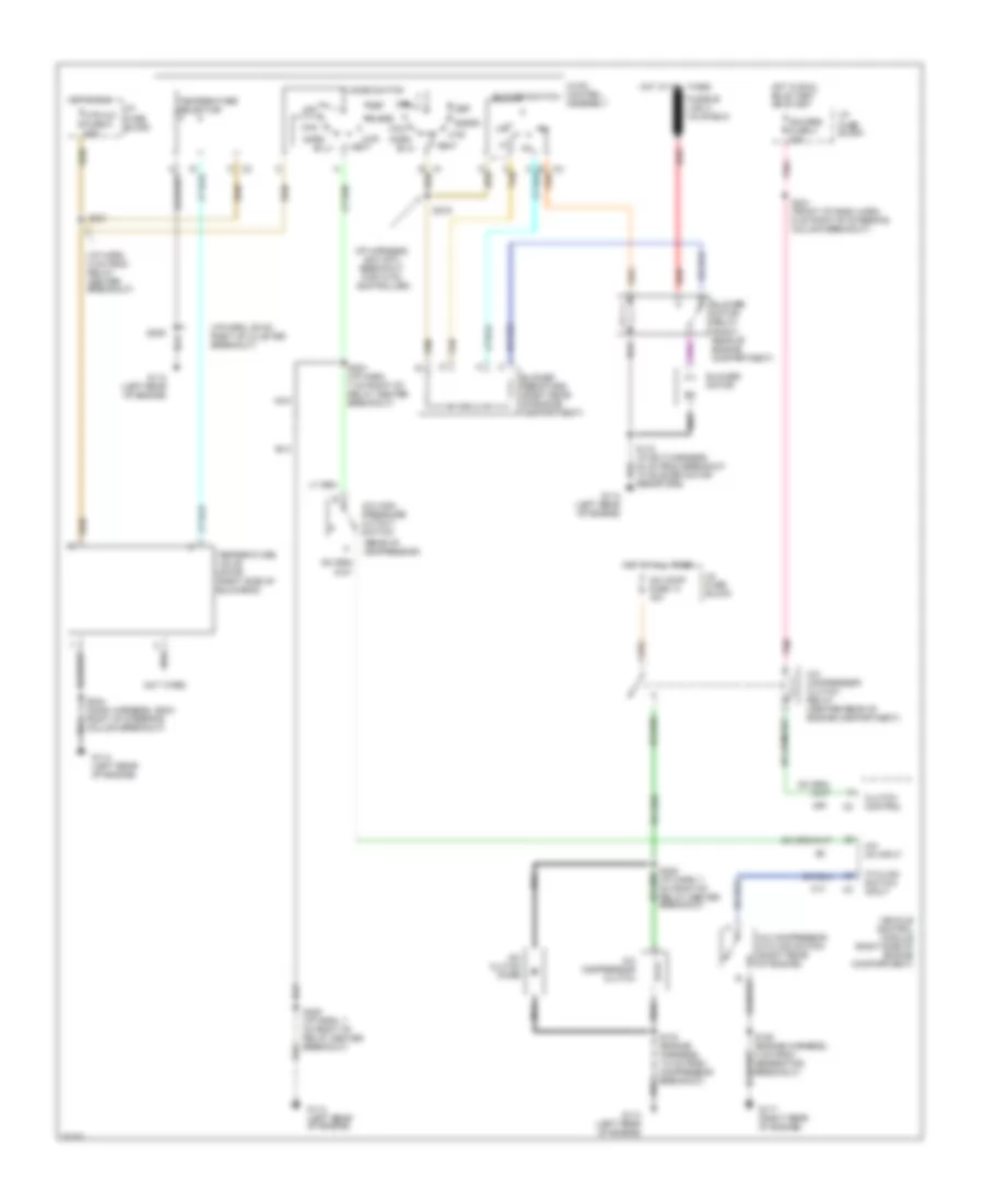
2.2L (VIN 4), A/C Wiring Diagram for GMC Sonoma 1997
 https://portal-diagnostov.com/license.html
Automotive Electricians Portal FZCO
Automotive Electricians Portal FZCO
https://portal-diagnostov.com/license.html
https://portal-diagnostov.com/license.html
Automotive Electricians Portal FZCO
Automotive Electricians Portal FZCO
List of elements for 2.2L (VIN 4), A/C Wiring Diagram for GMC Sonoma 1997:
- (cut wire)
- (i/p harn, 39 cm right of cluster breakout)
- (i/p harn, 5 cm from relay center breakout)
- (i/p harness, 6cm into breakout for hvac controller)
- +5v
- A tan
- A/c clutch diode
- A/c comp fuse 14 10a
- A/c compressor clutch
- A/c compressor clutch relay (engine compartment, left side of cowl)
- A/c on input
- A/c pressure
- A/c refrigerant pressure sensor
- Air temperature valve electric actuator (top of heater assembly)
- Bi-lv
- Blend
- Blower motor
- Blower motor relay (right rear of engine compt)
- Blower resistors (right rear of engine compartment)
- Blower switch
- Breakout)
- Clutch control
- Def
- G114 (left rear of engine)
- Gauges fuse 4 20a
- Ground
- Hot at all times
- Hot in run
- Hot in run, bulb test or start
- Htr
- Htr a/c fuse 6 25a
- Hvac control assembly
- I/p fuse block
- Max
- Mode switch
- Nca
- Norm
- Off
- Pnk
- Powertrain control module (behind right side of i/p)
- Red
- S103 (engine harn, 20 cm from a/c clutch connector)
- S104 (engine harn, 12 cm from a/c refrigerant pressure sensor breakout)
- S118 (i/p ext harness, 40 cm from breakout to blower motor resistors)
- S209
- S215
- S221
- S224 nca (i/p harness, 7 cm right of relay center breakout)
- S241 (dash harness, 6 cm right of steering column breakout)
- S244 (dash harness, 26 cm right of steering column breakout)
- Tan
- Temperature selector
- Vent
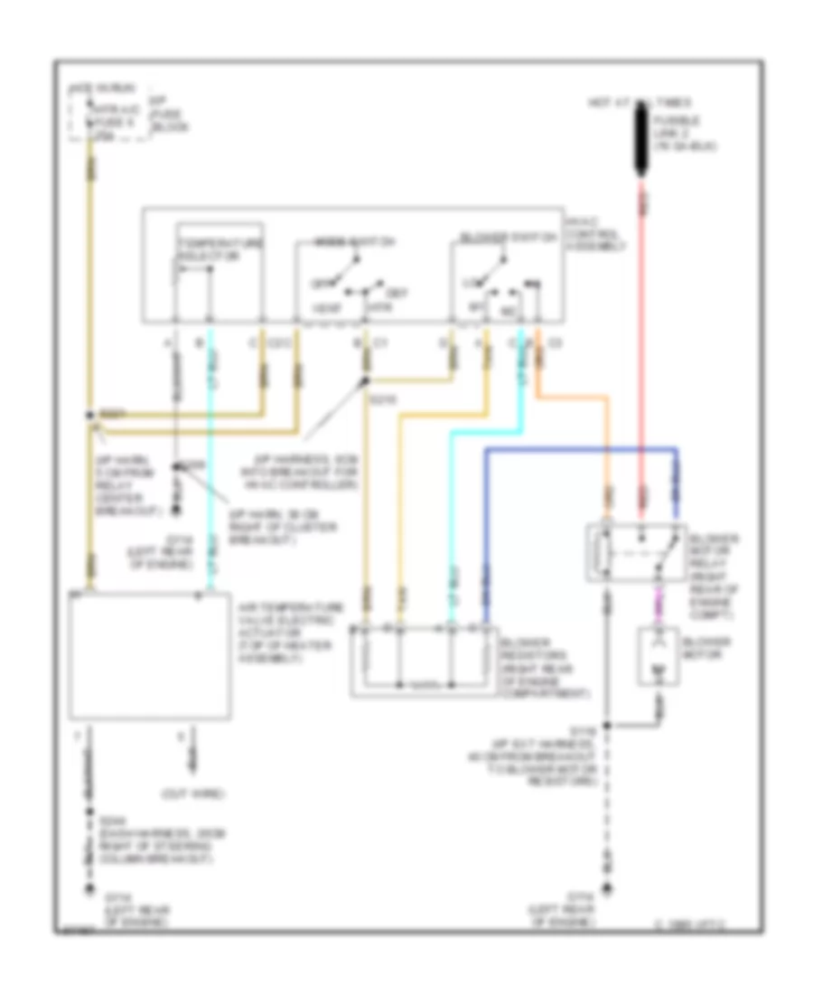
Heater Wiring Diagram for GMC Sonoma 1997
List of elements for Heater Wiring Diagram for GMC Sonoma 1997:
- (cut wire)
- (i/p harn, 39 cm right of cluster breakout)
- (i/p harn, 5 cm from relay center breakout)
- (i/p harness, 6cm into breakout for hvac controller)
- A tan
- Air temperature valve electric actuator (top of heater assembly)
- Blower motor
- Blower motor relay (right rear of engine compt)
- Blower resistors (right rear of engine compartment)
- Blower switch
- C 1995 vftc
- Def
- G114 (left rear of engine)
- Hot at all times
- Hot in run
- Htr
- Htr a/c fuse 6 25a
- Hvac control assembly
- I/p fuse block
- Mode switch
- Off
- Red
- S118 (i/p ext harness, 40 cm from breakout to blower motor resistors)
- S209
- S215
- S221
- S244 (dash harness, 26cm right of steering column breakout)
- Tan
- Temperature selector
- Vent
4.3L
4.3L (VIN W), A/C Wiring Diagram for GMC Sonoma 1997
List of elements for 4.3L (VIN W), A/C Wiring Diagram for GMC Sonoma 1997:
- (cut wire)
- (i/p harn, 39 cm right of cluster breakout)
- (i/p harn, 5 cm from relay center breakout)
- (i/p harness, 6cm into breakout for hvac controller)
- (rear of compressor)
- A tan
- A/c clutch diode
- A/c comp fuse 14 10a
- A/c compressor clutch
- A/c compressor clutch relay (center rear of engine compartment)
- A/c compressor cycling switch (right rear of engine)
- A/c high pressure cutout switch
- A/c on input
- Bi-lv
- Blend
- Blower motor
- Blower motor relay (right rear of engine compartment)
- Blower resistors (right rear of engine compartment)
- Blower switch
- Clutch control
- Cycling switch input
- Def
- G114 (left rear of engine)
- G117 (right rear of engine)
- Gauges fuse 4 20a
- Hot at all times
- Hot in run
- Hot in run, bulb test or start
- Htr
- Htr a/c fuse 6 20a
- Hvac control assembly
- I/p fuse block
- Max
- Mode switch
- Nca
- Norm
- Off
- Pnk
- Red
- S103 (engine harness, 7.5 cm from compressor breakout)
- S106 (engine harness, 4 cm from generator breakout)
- S118 (i/p ext harness, 40 cm from breakout to blower motor resistors)
- S209
- S215
- S221
- S224 (i/p harn, 7 cm right of relay center breakout)
- S225 (i/p harn, 7 cm right of relay center breakout)
- S241 (front of dash harn, 6 cm right of steering column breakout)
- S244 (dash harness, 26cm right of steering column breakout)
- Tan
- Temperature selector
- Temperature valve motor (right side of bulkhead)
- Vehicle control module (right side of engine compartment)
- Vent
4.3L (VIN X), A/C Wiring Diagram for GMC Sonoma 1997
List of elements for 4.3L (VIN X), A/C Wiring Diagram for GMC Sonoma 1997:
- (cut wire)
- (i/p harn, 39 cm right of cluster breakout)
- (i/p harn, 5 cm from relay center breakout)
- (i/p harness, 6cm into breakout for hvac controller)
- (rear of compressor)
- A tan
- A/c clutch diode
- A/c comp fuse 14 10a
- A/c compressor clutch
- A/c compressor clutch relay (center rear of engine compartment)
- A/c compressor cycling switch (right rear of engine)
- A/c high pressure cutout switch
- A/c on input
- Bi-lv
- Blend
- Blower motor
- Blower motor relay (right rear of engine compartment)
- Blower resistors (right rear of engine compartment)
- Blower switch
- Clutch control
- Cycling switch input
- Def
- G114 (left rear of engine)
- G117 (right rear of engine)
- Gauges fuse 4 20a
- Hot at all times
- Hot in run
- Hot in run, bulb test or start
- Htr
- Htr a/c fuse 6 20a
- Hvac control assembly
- I/p fuse block
- Max
- Mode switch
- Nca
- Norm
- Off
- Pnk
- Red
- S103 (engine harness, 7.5 cm from compressor breakout)
- S106 (engine harness, 4 cm from generator breakout)
- S118 (i/p ext harness, 40 cm from breakout to blower motor resistors)
- S209
- S215
- S221
- S224 (i/p harn, 7 cm right of relay center breakout)
- S225 (i/p harn, 7 cm right of relay center breakout)
- S241 (front of dash harn, 6 cm right of steering column breakout)
- S244 (dash harness, 26cm right of steering column breakout)
- Tan
- Temperature selector
- Temperature valve motor (right side of bulkhead)
- Vehicle control module (right side of engine compartment)
- Vent
Heater Wiring Diagram for GMC Sonoma 1997
List of elements for Heater Wiring Diagram for GMC Sonoma 1997:
- (cut wire)
- (i/p harn, 39 cm right of cluster breakout)
- (i/p harn, 5 cm from relay center breakout)
- (i/p harness, 6cm into breakout for hvac controller)
- A tan
- Air temperature valve electric actuator (top of heater assembly)
- Blower motor
- Blower motor relay (right rear of engine compt)
- Blower resistors (right rear of engine compartment)
- Blower switch
- C 1995 vftc
- Def
- G114 (left rear of engine)
- Hot at all times
- Hot in run
- Htr
- Htr a/c fuse 6 25a
- Hvac control assembly
- I/p fuse block
- Mode switch
- Off
- Red
- S118 (i/p ext harness, 40 cm from breakout to blower motor resistors)
- S209
- S215
- S221
- S244 (dash harness, 26cm right of steering column breakout)
- Tan
- Temperature selector
- Vent
ANTI-LOCK BRAKES
2.2L
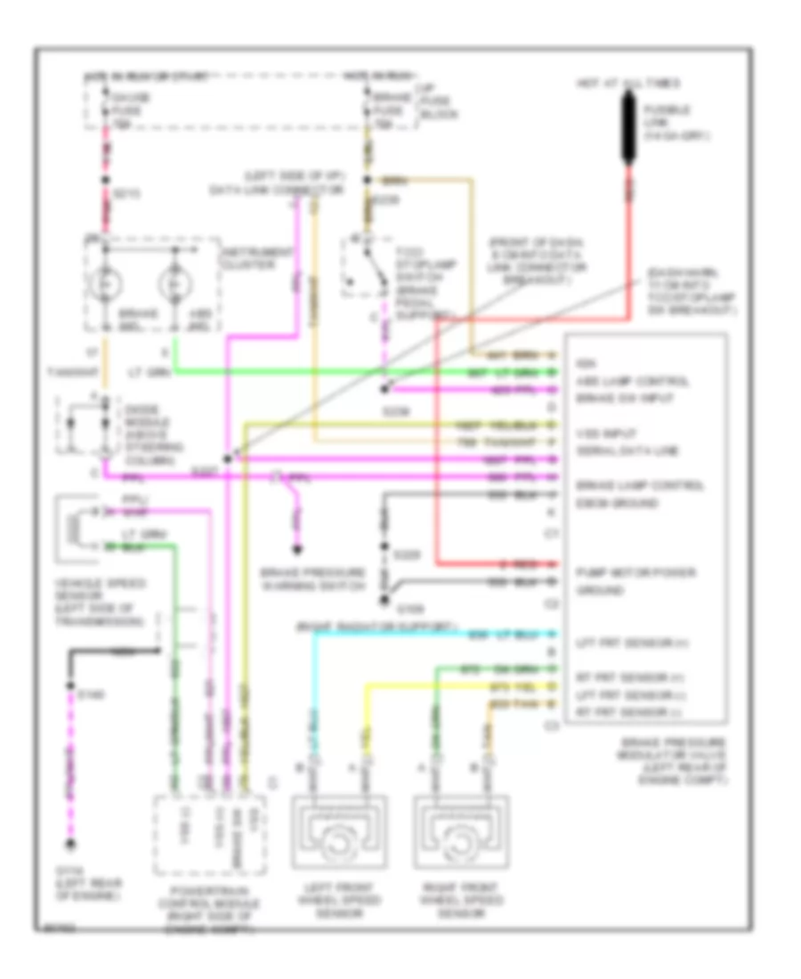
2.2L (VIN 4), Anti-lock Brake Wiring Diagrams for GMC Sonoma 1997
List of elements for 2.2L (VIN 4), Anti-lock Brake Wiring Diagrams for GMC Sonoma 1997:
- (dash harn, 11 cm into tcc/stoplamp sw breakout)
- (front of dash, 8 cm into data link connector breakout)
- (left side of i/p)
- (right radiator support)
- Abs ind
- Abs lamp control
- Brake fuse 10a
- Brake ind
- Brake lamp control
- Brake pressure modulator valve (left rear of engine compt)
- Brake pressure warning switch
- Brake sw
- Brake sw input
- Data link connector
- Diode module (above steering column)
- Ebcm ground
- G109
- G114 (left rear of engine)
- Gauge fuse 10a
- Ground
- Hot at all times
- Hot in run
- Hot in run or start
- I/p fuse block
- Ign
- Instrument cluster
- Left front wheel speed sensor
- Lft frt sensor (+)
- Lft frt sensor (-)
- Nca
- Pnk
- Powertrain control module (right side of engine compt)
- Pump motor power
- Red
- Right front wheel speed sensor
- Rt frt sensor (+)
- Rt frt sensor (-)
- S140
- S213 pnk
- S227
- S229
- S238
- Serial data line
- Tan
- Vehicle speed sensor (left side of transmission)
- Vss
- Vss (+)
- Vss (-)
- Vss input
4.3L
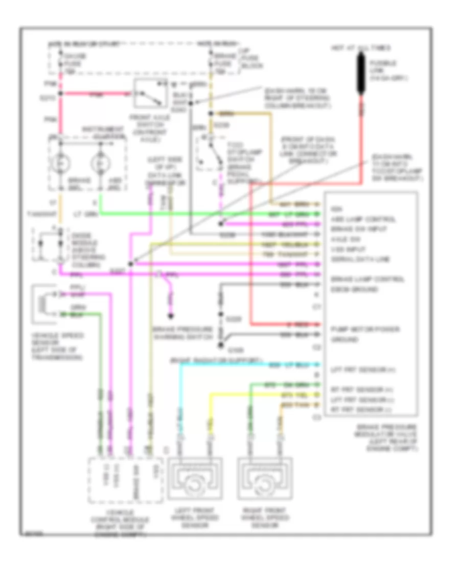
4.3L (VIN W), Anti-lock Brake Wiring Diagrams for GMC Sonoma 1997
List of elements for 4.3L (VIN W), Anti-lock Brake Wiring Diagrams for GMC Sonoma 1997:
- (dash harn, 11 cm into tcc/stoplamp sw breakout)
- (dash harn, 19 cm right of steering column breakout)
- (front of dash, 8 cm into data link connector breakout)
- (left side of i/p)
- (right radiator support)
- Abs ind
- Abs lamp control
- Axle sw
- Brake fuse 10a
- Brake ind
- Brake lamp control
- Brake pressure modulator valve (left rear of engine compt)
- Brake pressure warning switch
- Brake sw
- Brake sw input
- Data link connector
- Diode module (above steering column)
- Ebcm ground
- Front axle switch (on front axle)
- G109
- Gauge fuse 10a
- Ground
- Hot at all times
- Hot in run
- Hot in run or start
- I/p fuse block
- Ign
- Instrument cluster
- Left front wheel speed sensor
- Lft frt sensor (+)
- Lft frt sensor (-)
- Pnk
- Pump motor power
- Red
- Right front wheel speed sensor
- Rt frt sensor (+)
- Rt frt sensor (-)
- S213
- S227
- S229
- S238
- S239
- S243
- Serial data line
- Tan
- Vehicle control module (right side of engine compt)
- Vehicle speed sensor (left side of transmission)
- Vss
- Vss (+)
- Vss (-)
- Vss input
COMPUTER DATA LINES
2.2L
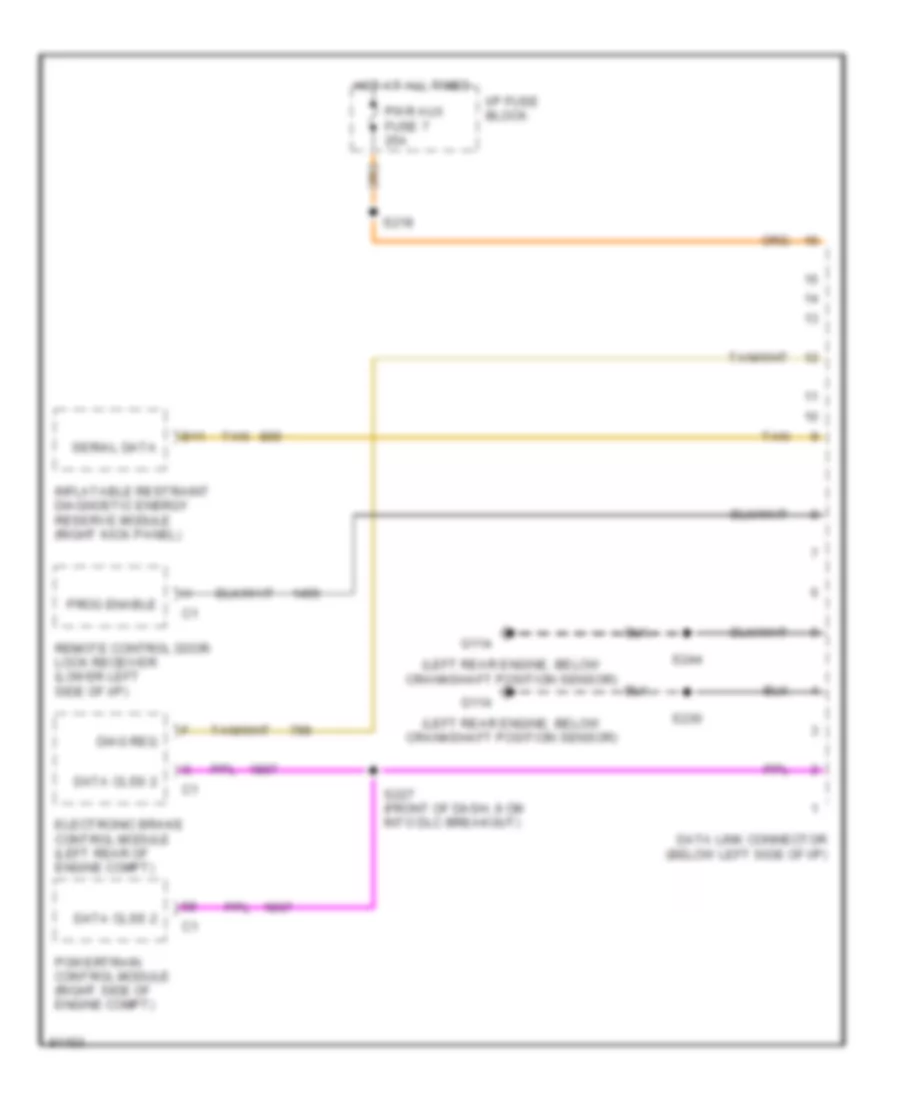
2.2L (VIN 4), Computer Data Lines for GMC Sonoma 1997
List of elements for 2.2L (VIN 4), Computer Data Lines for GMC Sonoma 1997:
- (left rear engine, below crankshaft position sensor)
- B11
- Data clss 2
- Data link connector (below left side of i/p)
- Diag req
- Electronic brake control module (left rear of engine compt)
- G114
- Hot at all times
- I/p fuse block
- Inflatable restraint diagnostic energy reserve module (right kick panel)
- Powertrain control module (right side of engine compt)
- Prog enable
- Pwr aux fuse 7 25a
- Remote control door lock receiver (lower left side of i/p)
- S218
- S227 (front of dash, 8 cm into dlc breakout)
- S230
- S244
- Serial data
- Tan
4.3L
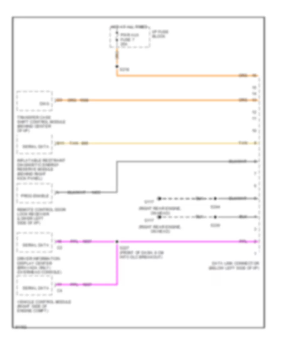
4.3L (VIN W), Computer Data Lines for GMC Sonoma 1997
List of elements for 4.3L (VIN W), Computer Data Lines for GMC Sonoma 1997:
- (right rear engine, on head)
- B11
- Data link connector (below left side of i/p)
- Diag
- Driver information display center (bravada only) (overhead console)
- G117
- Hot at all times
- I/p fuse block
- Inflatable restraint diagnostic energy reserve module (behind right kick panel)
- Prog enable
- Pwr aux fuse 7 25a
- Remote control door lock receiver (lower left side of i/p)
- S218
- S227 (front of dash, 8 cm into dlc breakout)
- S230
- S244
- Serial data
- Tan
- Transfer case shift control module (behind center of i/p)
- Vehicle control module (right side of engine compt)
CRUISE CONTROL
2.2L
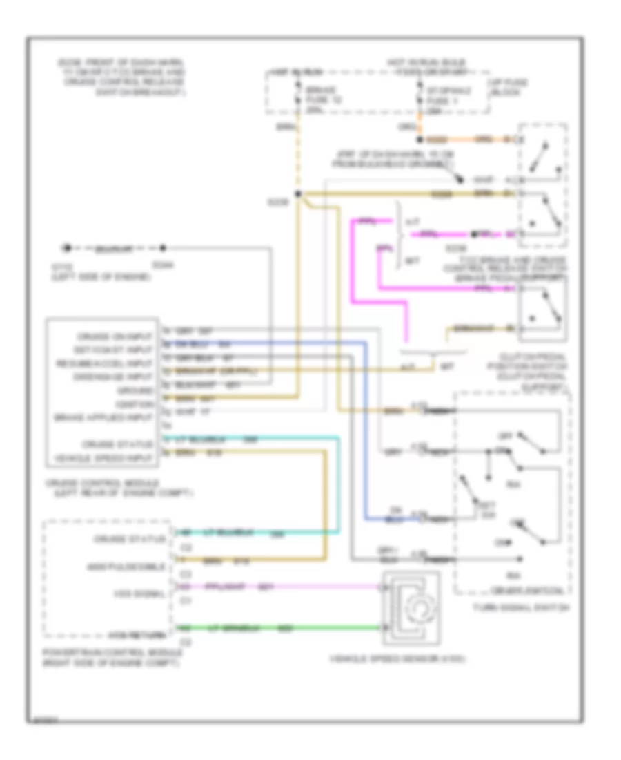
2.2L (VIN 4), Cruise Control Wiring Diagram for GMC Sonoma 1997
List of elements for 2.2L (VIN 4), Cruise Control Wiring Diagram for GMC Sonoma 1997:
- (frt of dash harn, 15 cm from bulkhead grommet)
- (left rear of engine compt)
- (s238: front of dash harn, 11 cm into tcc brake and cruise control release switch breakout)
- 4000 pulses/mile
- A/t
- A12
- A13
- A14
- A15
- Brake fuse 12 10a
- Clutch pedal position switch (clutch pedal
- Cruise control module
- Cruise on input
- Cruise status
- Cruise switch
- Disengage input
- G112 (left side of engine)
- Ground
- Hot in run
- Hot in run, bulb
- I/p fuse block
- Ignition
- M/t
- Nca
- Off
- Powertrain control module (right side of engine compt)
- R/a
- Resume/accel input
- S222
- S228
- S238
- S239
- S244
- Set sw
- Set/coast input
- Stop/haz fuse 1 20a
- Support)
- Tcc brake and cruise control release switch (brake pedal support)
- Test or start
- Turn signal switch
- Vehicle speed input
- Vehicle speed sensor (vss)
- Vss return
- Vss signal
4.3L
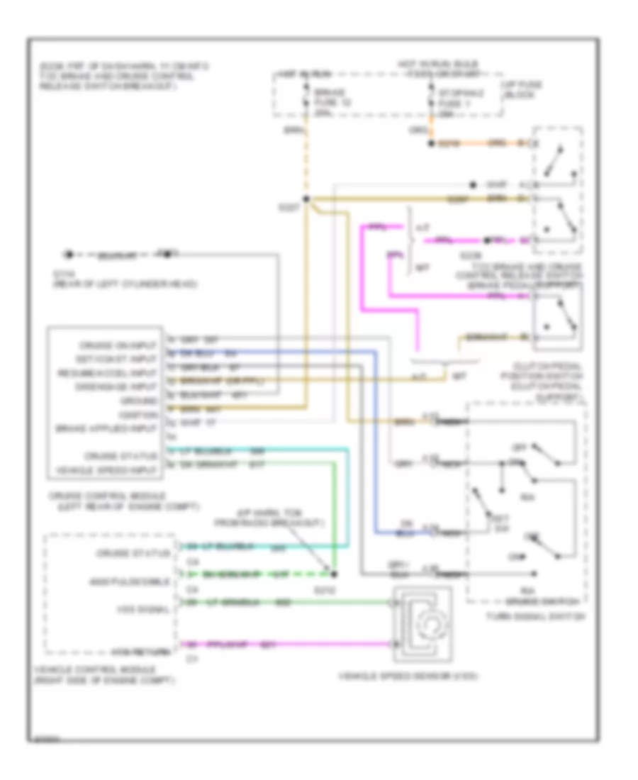
4.3L (VIN W), Cruise Control Wiring Diagram for GMC Sonoma 1997
List of elements for 4.3L (VIN W), Cruise Control Wiring Diagram for GMC Sonoma 1997:
- (i/p harn, 7cm from radio breakout)
- (left rear of engine compt)
- (s238: frt of dash harn, 11 cm into tcc brake and cruise control release switch breakout)
- 4000 pulses/mile
- A/t
- A12
- A13
- A14
- A15
- Brake fuse 12 10a
- Clutch pedal position switch (clutch pedal
- Cruise control module
- Cruise on input
- Cruise status
- Cruise switch
- Disengage input
- G114 (rear of left cylinder head)
- Ground
- Hot in run
- Hot in run, bulb
- I/p fuse block
- Ignition
- M/t
- Nca
- Off
- R/a
- Resume/accel input
- S212
- S219
- S227
- S233
- S238
- S297
- Set sw
- Set/coast input
- Stop/haz fuse 1 20a
- Support)
- Tcc brake and cruise control release switch (brake pedal support)
- Test or start
- Turn signal switch
- Vehicle control module (right side of engine compt)
- Vehicle speed input
- Vehicle speed sensor (vss)
- Vss return
- Vss signal
ENGINE PERFORMANCE
2.2L
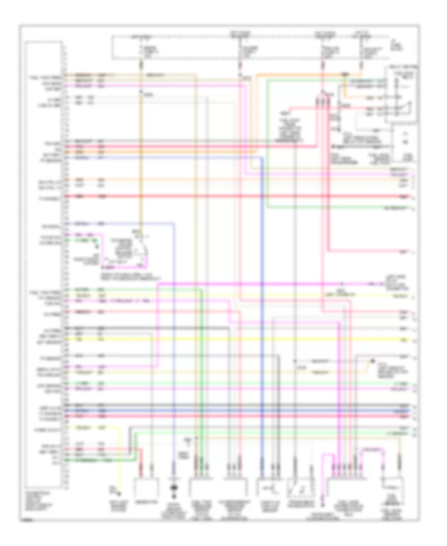
2.2L (VIN 4), Engine Performance Wiring Diagrams (1 of 3) for GMC Sonoma 1997
List of elements for 2.2L (VIN 4), Engine Performance Wiring Diagrams (1 of 3) for GMC Sonoma 1997:
- (a/t only)
- (body harn)
- (front of dash harn, 11cm from tcc brake sw breakout)
- (left lower i/p)
- (left side of i/p) data link connector
- 5v ref
- A/c pres
- A/c refrigerant pressure sensor (at a/c evaporator)
- A/c req sig
- Air conditioning system
- All times
- Anti-lock brakes system
- Battery
- Brake fuse 12 10a
- Ckp ref
- Cmp sens
- Ecm batt fuse 9 20a
- Ecm ign fuse 10 20a
- Ect sensor
- Egr valve
- Flbm 5v ref
- Flbm sig
- Fuel level buffer module (under glove box)
- Fuel level sensor
- Fuel level sensor/ fuel pump
- Fuel pump
- Fuel pump prime connector (left rear corner of engine compt)
- Fuel pump relay
- Fuel tank pres
- Fuel tank pressure sensor (top of fuel tank)
- G114 (left rear of eng below ckp sensor)
- G416 (left rear crossmember)
- Gauges fuse 4 10a
- Gen term f
- Gen term l
- Generator
- Hi-res vs out
- Hot at
- Hot in run
- Hot in run or start
- I/p fuse block
- Ign
- Ign ctrl 1-4
- Ign ctrl 2-3
- Inj 1
- Inj 2
- Instrument cluster system
- Knock sensor (lower right side of eng)
- Ks signal
- Map sensor
- P/ n
- Pcm gnd
- Pcm ground
- Pnk
- Pnp sw in
- Powertrain control module (right side of eng compt)
- Red
- Relay center
- S105
- S106
- S209
- S213
- S220
- S227
- S238
- S239
- S401
- Serial data
- Tcc bk sw
- Tcc brake/ cruise control release switch
- Tft sensor
- Throttle position sensor
- Tp sensor
- Transmission range switch
- Tx range a
- Tx range b
- Tx range c
- Vss high
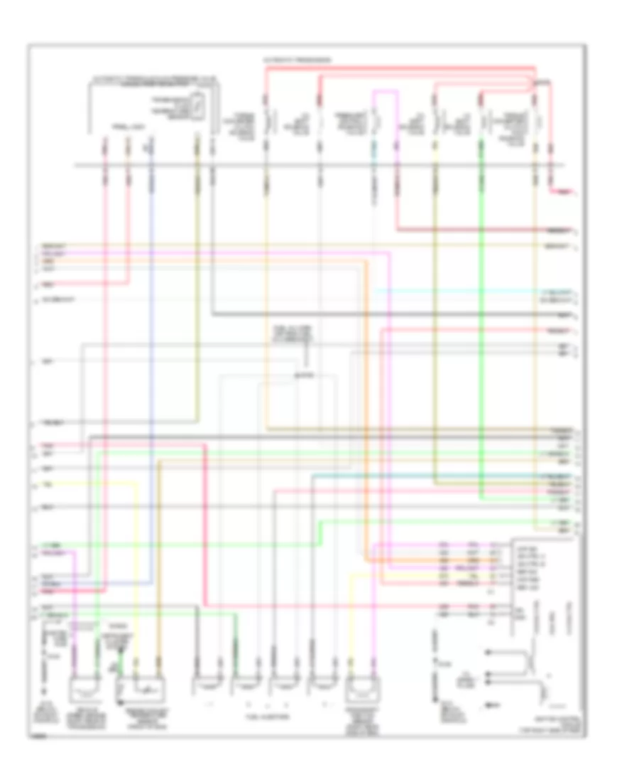
2.2L (VIN 4), Engine Performance Wiring Diagrams (2 of 3) for GMC Sonoma 1997
List of elements for 2.2L (VIN 4), Engine Performance Wiring Diagrams (2 of 3) for GMC Sonoma 1997:
- (fuel inj harn, 3cm from fuel inj 3 breakout)
- 1-2 shift solenoid valve
- 1-4 coil ctrl
- 2-3 coil ctrl
- 2-3 shift solenoid valve
- 3-2 shift solenoid valve
- Automatic transaxle fluid pressure valve manual position switch
- Automatic transmission
- C pnk
- Ckp gnd
- Ckp sig
- Coil pos
- Crankshaft position sensor (right rear side of eng)
- Engine coolant temperature sensor (front of eng)
- Fuel injectors
- G112 (below exhaust manifold)
- Gnd
- Ign
- Ign ctrl a
- Ign ctrl b
- Ignition control module (top right side of eng)
- Instrument cluster system
- Nca
- Pnk
- Pressure control solenoid valve
- Prndl logic
- Red
- Ref low
- Ref sig
- S106
- S128
- S129
- S140
- Shield
- Tan
- To spark plugs
- Torque converter clutch pwm solenoid valve
- Torque converter clutch solenoid valve
- Transmission fluid temperature sensor
- Twisted wire pair
- Vehicle speed sensor (right rear of transmission)
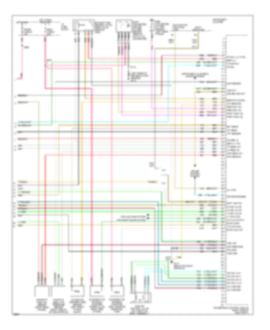
2.2L (VIN 4), Engine Performance Wiring Diagrams (3 of 3) for GMC Sonoma 1997
List of elements for 2.2L (VIN 4), Engine Performance Wiring Diagrams (3 of 3) for GMC Sonoma 1997:
- (left rear of eng below ckp sensor) g114
- (m/t)
- 1-2 ss valve
- 2-3 ss valve
- 3-2 ss valve
- 422 (a/t)
- 456 (m/t)
- A/ pres +5v
- A/c clutch rly
- A/t
- Air conditioning system
- Camshaft position sensor (right rear of eng)
- Cmp sens b+
- Cmp sens gnd
- Cooling fans system
- Cruise control system
- Cruise engaged
- Cruise vss out
- Ect sens
- Egr pintle pos
- Egr vlv
- Egr vlv +5v
- Eng-i fuse 5 20a
- Evap can vnt
- Evap canp
- Evaporative emission canister purge valve (right side of eng)
- Evaporative emission canister vent solenoid (near fuel tank)
- Exhaust gas recirculation (egr) valve (rear of eng)
- F pump rly
- Flbm gnd
- G112 (below exhaust manifold)
- Hot in run
- Hot in run or start
- I/p fuse block
- Iac coil a hi
- Iac coil a lo
- Iac coil b hi
- Iac coil b lo
- Iat sens
- Iat sens sig
- Icm ref lo
- Idle air control valve (on throttle body assembly)
- Inj 3 driver
- Inj 4 driver
- Instrument cluster
- Instrument cluster & sound systems
- Intake air temperature sensor (left front of eng compt)
- Lt fan ctrl
- M/t
- Malfunction indicator lamp
- Manifold absolute pressure sensor (right side of intake manifold)
- Map sens +5v
- Map sensor
- Mil ctrl
- Nca
- Pc sol
- Pc sol vlv ctrl
- Pcm gnd
- Pnk
- Pnk a
- Post conv o2
- Post- converter heated oxygen sensor (rear of catalytic converter)
- Powertrain control module (right side of eng compt)
- Pre conv o2
- Pre- converter oxygen sensor (left rear of eng)
- Red
- Red a
- S106
- S107
- S112
- S266
- Shft ind/tcc
- Shift indicator
- Tan
- Tan b
- Tan/bk
- Tcc pwm sol
- Tft sensor
- Tp sens +5v
- Trans fuse 24 10a
- Vss low
- Vss out
4.3L
4.3L (VIN W), Engine Performance Wiring Diagrams (1 of 4) for GMC Sonoma 1997
List of elements for 4.3L (VIN W), Engine Performance Wiring Diagrams (1 of 4) for GMC Sonoma 1997:
- (oxygen sensor harn, 10cm from 4-pin conn joining oxygen sensor extension harn)
- (rear of right cylinder head)
- (top right center of engine) evaporative emissions canister purge solenoid valve
- (upper left side of throttle body) idle air control valve motor
- 1-2 shift sol. ctrl
- 2-3 shift sol. ctrl
- 3-2 ctrl sol. ctrl
- A/c comp rly ctrl
- Air conditioning system
- Anti-lock brakes system
- Cam posit sens rtn
- Cam posit sens sig
- Camshaft position sensor (side of distributor)
- Crank posit sens sig
- Crankshaft position sensor (behind right side of engine crankshaft pulley)
- Ect sens input
- Egr posit input
- Egr valve ctrl
- Evap can vent valve
- Evap sol purge ctrl
- G114 (rear of left cylinder head)
- G117
- Hall effect sensor
- Iat temp sens sig
- Idle air ctrl (iac) a hi
- Idle air ctrl (iac) b lo
- Inj no.1 ctrl
- Inj no.2 ctrl
- Inj no.3 ctrl
- Inj no.4 ctrl
- Inj no.5 ctrl
- Inj no.6 ctrl
- Knock sens sig
- Knock sensor (top left rear of engine)
- Left front heated oxygen sensor
- Left sens hi
- Left sens lo
- Map sens input
- Mass air flow sens
- Nca
- Pnk
- Pnk c
- Pnk pnk pnk pnk pnk
- Post-catalyst sens hi
- Post-catalyst sens lo
- Power
- Pre-catalyst sens hi
- Pre-catalyst sens lo
- Pre-converter heated oxygen sensor
- Rear whl speed out
- Right front heated oxygen sensor
- Right sens hi
- Right sens lo
- S106
- S112
- S140
- S317
- S318
- Tan
- Tcc on/off sol. ctrl
- Tcc pwm sol ctrl
- Throttle posit sens
- Trans temp sens sig
- Twisted wire pair
- Vapor press
- Vcm ground
- Vehicle control module (vcm) (right side of engine compt)
- Vehicle speed sensor (rear of transmission)
- Vss rtn
- Vss signal
4.3L (VIN W), Engine Performance Wiring Diagrams (2 of 4) for GMC Sonoma 1997
List of elements for 4.3L (VIN W), Engine Performance Wiring Diagrams (2 of 4) for GMC Sonoma 1997:
- 1-2 shift sol.
- 2-3 shift sol.
- 3-2 control sol.
- Automatic transmission
- Automatic transmission fluid pressure manual valve position switch
- D2 sw
- D3 sw
- D4 sw
- Ecm ign fuse 10 20a
- Eng fuse 5 20a
- Evaporative emission canister vent valve (near fuel tank)
- Exhaust gas recirculation valve (top front of engine)
- Fuel inj. no.1
- Fuel inj. no.2
- Fuel inj. no.3
- Fuel inj. no.4
- Fuel inj. no.5
- Fuel inj. no.6
- Hot in run or start
- I/p fuse block
- Lo sw
- Nca
- Pnk
- Pnk pnk pnk tan
- Post-converter heated oxygen sensor
- Pressure control solenoid valve
- Red
- Rev sw
- S105
- S107
- Tan
- Tcc on/off sol.
- Tcc pwm sol.
- Transmission fluid temperature sensor
4.3L (VIN W), Engine Performance Wiring Diagrams (3 of 4) for GMC Sonoma 1997
List of elements for 4.3L (VIN W), Engine Performance Wiring Diagrams (3 of 4) for GMC Sonoma 1997:
- (eng harn, 6cm from linear egr valve sol breakout)
- (eng harn, 8cm from generator breakout)
- (left rear of chassis on crossmember) g416
- 12v in
- 5v ref
- Ecm batt fuse 9 20a
- Engine coolant temperature sensor (top front of engine, in thermostat housing)
- Fuel level sensor/ fuel pump (inside fuel tank)
- Fuel pump prime connector (left rear of engine compt)
- Fuel pump relay
- Fuel pump switch/ engine oil pressure gauge sensor (near distributor)
- Fuel tank vapor pressure sensor
- G114 (rear of left cylinder head)
- G117 (rear of right cylinder head)
- Gauge input oil pressure
- Gauges fuse 4 10a
- Gnd
- Hot at all times
- Hot in off, run or start
- Hot in run or start
- I/p fuse block
- Input fuel gauge
- Input odometer speedometer &
- Instrument cluster
- Intake air temperature sensor (left front of engine compt)
- Maf sig
- Malfunction indicator lamp (mil)
- Manifold absolute pressure sensor (top right side of engine)
- Mass air flow sensor (maf) (left front of engine compt)
- Pickup
- Pnk
- Red
- Relay center (left side of i/p)
- Rtn
- S100 (eng harn, 30cm from vcm breakout)
- S101
- S102
- S106
- S108
- S209
- S213 pnk
- S220
- S241
- S250 (dash harn, 13cm from 4wd ind breakout)
- S266
- Shift indicator (w/ m/t)
- Tachometer input
- Tan
- Tan a
- Throttle position sensor
- Trans fuse 24 10a
- Utility
- Vapor
4.3L (VIN W), Engine Performance Wiring Diagrams (4 of 4) for GMC Sonoma 1997
List of elements for 4.3L (VIN W), Engine Performance Wiring Diagrams (4 of 4) for GMC Sonoma 1997:
- (i/p harn, 21cm from 6-pin conn breakout at right side of i/p)
- (rear of left cylinder head)
- (rear of right cylinder head)
- 4wd f whl lock in
- 4wd low ind sig
- 5v ref b
- 5v ref. voltage
- 5v return
- A/c request (hi)
- A/c request (lo)
- Air conditioning system
- Anti-lock brakes system
- Brake switch input
- Bravada
- Check eng lp out
- Cpp sw in
- Cruise control system
- Cruise control system, sound system & transfer case circuit
- Cruise engaged sig
- Data link connector (dlc-partial) (lower left side of i/p)
- Distributor (top rear of engine)
- Driver's information display center
- Electronic ignition control module (top right of engine)
- Est output sig
- Front axle switch (right of differential)
- Fuel level buffer module (under glove box)
- Fuel level d
- Fuel level mod out
- Fuel level rtn
- Fuel pump rly ctrl
- Fused ign (run)
- Fused ign (run/start)
- G114
- G117
- Gauge ctrl l
- Ground
- High voltage coil wire
- Hot in run
- I/p fuse block
- Ign timing sig.
- Ignition coil (top right side of engine)
- Ignition feed
- M4 brake fuse 12 10a n3
- Mod out m
- Pnk
- Pnk a
- Power a
- Power b(+)
- Press ctrl sol lo
- Press ctrl sol. hi
- Red
- S109
- S227 (front of dash, 8cm from data link connector breakout)
- S238 (dash harn, 11cm from tcc brake switch breakout)
- S239
- S298
- Sensor in c
- Serial data sig
- Service circuit-power
- Shift ind ctrl
- Spark plugs
- Tach. sig.
- Trans press sig-bit 1
- Trans press sig-bit 2
- Trans press sig-bit 3
- Transfer case circuit
- Utility
- Vehicle control module (vcm) (right side of engine compt)
- Vss in
- Vss sig
EXTERIOR LIGHTS
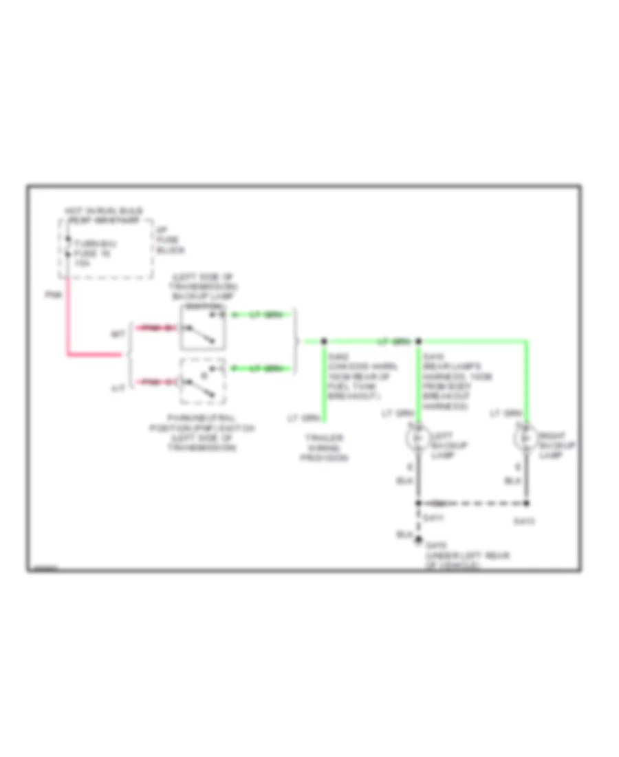
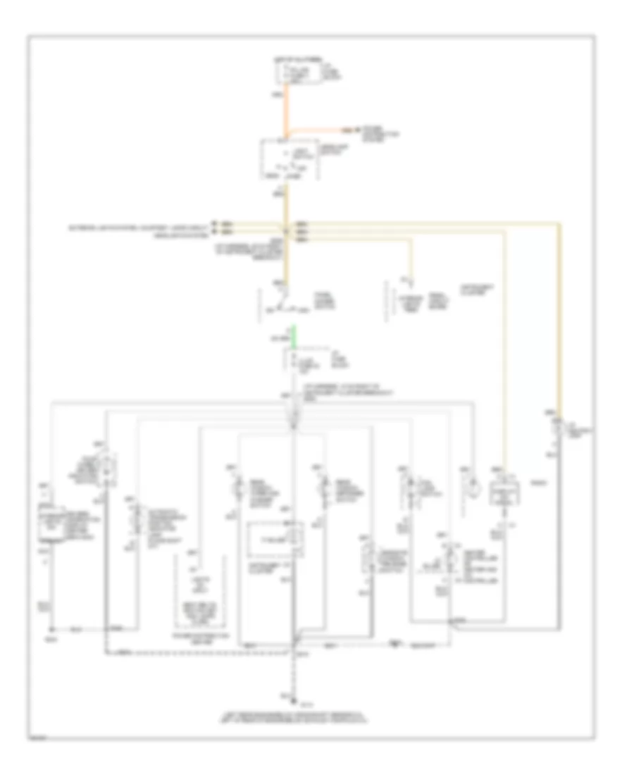
Back-up Lamps Wiring Diagram for GMC Sonoma 1997
List of elements for Back-up Lamps Wiring Diagram for GMC Sonoma 1997:
- (left side of transmission) backup lamp switch
- A/t
- G416 (under left rear of vehicle)
- Hot in run, bulb test or start
- I/p fuse block
- Left backup lamp
- M/t
- Park/neutral position (pnp) switch (left side of transmission)
- Pnk
- Right backup lamp
- S402 (chassis harn, 10cm rear of fuel tank breakout)
- S410 (rear lamps harness, 10cm from body breakout harness)
- S411
- S413
- Trailer wiring provision
- Turn b/u fuse 16 15a
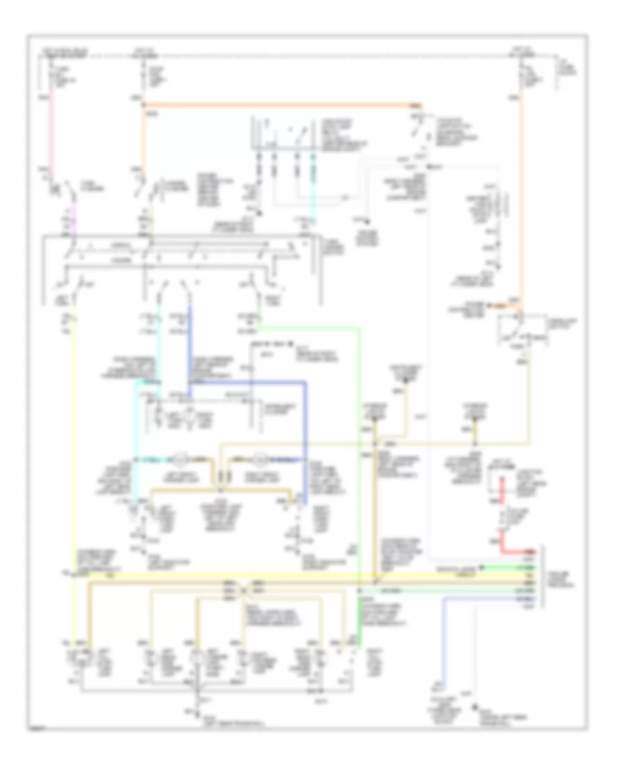
Exterior Lamps Wiring Diagram for GMC Sonoma 1997
List of elements for Exterior Lamps Wiring Diagram for GMC Sonoma 1997:
- (body harness, left rear of engine compartment)
- (chassis harn, 20cm rear of evap canister vent valve breakout) s405
- (chassis harn, 8cm forward of tail lamp harn breakout)
- (chassis harn, 8cm forward of tail lamp harn breakout) s408
- (dash harness, 8cm left of steering column harness breakout) s236
- (dash harness, left rear of engine compartment) s234
- (on brake pedal support bracket)
- A right rear side marker lamp b
- Auxiliary lead (taped near junction block)
- Backup lamps circuit
- Center high mount stop lamp
- Cruise control system
- G108 (left radiator support)
- G109 (right radiator support)
- G114 (rear of left cylinder head)
- G117 (rear of right cylinder head)
- G416 (inside left rear frame rail)
- G416 (left rear frame rail)
- Hazard
- Hazard flasher
- Head
- Headlamp switch
- High mount stop lamp relay (4.3l only) (center rear of engine compt)
- Hot at all times
- Hot in run, bulb test or start
- I/p fuse block
- In-line fuse 30a
- Instrument cluster
- Instrument cluster system
- Interior lights system
- Junction block (left rear engine compt)
- Left front marker lamp
- Left front park/ turn lamp
- Left license lamp (fleet- side)
- Left rear side marker lamp
- Left tail/ stop/ turn lamp
- Left turn
- Left turn indic
- Normal
- Off
- Park
- Pk lps fuse 3 20a
- Pnk
- Power distribution center
- Power distribution center (behind center of dash)
- Red
- Right (or rear) license lamp
- Right front marker lamp
- Right front park/ turn lamp
- Right tail/ stop/ turn lamp
- Right turn
- Right turn indic
- S112 (or s109)
- S120
- S122 (forward lamp harn, 6cm right of left head- lamp brkout)
- S123 (forward lamp harness, 6cm left of left headlamp breakout)
- S125 (forward lamp harn, 7cm left of right head- lamp brkout)
- S126
- S206 (i/p harness, 25cm right of i/p cluster harness breakout)
- S210
- S222
- S228 (body harness, left rear of engine compartment)
- S302
- S409
- S411
- S412 (rear lamps harn, 15cm right of body harness breakout)
- S413
- Stop haz fuse 1 20a
- Tcc/stop lamp switch
- Trailer wiring provision
- Turn b/u fuse 16 15a
- Turn flasher
- Turn- hazard switch
GROUND DISTRIBUTION
2.2L
2.2L (VIN 4), Ground Distribution Wiring Diagram (1 of 2) for GMC Sonoma 1997
List of elements for 2.2L (VIN 4), Ground Distribution Wiring Diagram (1 of 2) for GMC Sonoma 1997:
- (cut
- (forward lamp harness, 7 cm left of ground breakout to right radiator support)
- (front of dash harness, 17 cm right of bulkhead grommet)
- (rear of left cylinder head)
- A/c request voltage drop resistor
- A12
- Automatic transmission position indicator lamp
- Base
- Battery
- Brake pressure modulator valve
- Brake pressure warning switch
- Cigarette lighter
- Data link connector
- Drl relay
- Egr valve
- Electronic ignition control module
- From breakout to connector above brake booster)
- G108 (left radiator support)
- G109 (right radiator support)
- G112 (left side of engine below exhaust manifold)
- G112 (left side of engine, below exhaust manifold)
- G114
- G118 (right front frame)
- G120 (right fwd eng block)
- High mounted stop lamp
- I/p compartment lamp
- Ignition switch
- Inflatable restraint diagnostic energy reserve module
- Inside rear view mirror
- Instrument cluster
- Left auxiliary power outlet
- Left front park/turn lamp
- Left front side door jamb switch
- Left horn
- Left inflatable restraint discriminating sensor
- Left low beam headlamp (w/ composite lamps)
- Left sunshade mirror lamp
- Nca
- Non-base
- Panel dimmer switch
- Park pawl actuator
- Powertrain control module
- Relay center
- Right auxiliary power outlet
- Right front park/turn lamp
- Right front side door jamb switch
- Right headlamp (w/ sealed beam lamps)
- Right high beam headlamp (w/ composite lamps)
- Right horn
- Right inflatable restraint discriminating sensor
- Right low beam headlamp (w/ composite lamps)
- Right sunshade mirror lamp
- S120 (forward lamp harness, 7 cm right of left headlamp breakout)
- S210 (i/p harness, 43 cm right of instrument cluster breakout)
- S229
- S302
- Steering column shift lever actuator
- Tan
- To g114 (diagram 2 of 2)
- Under- hood lamp
- Windshield washer pump
- Windshield wiper pulse control module
- Wire)
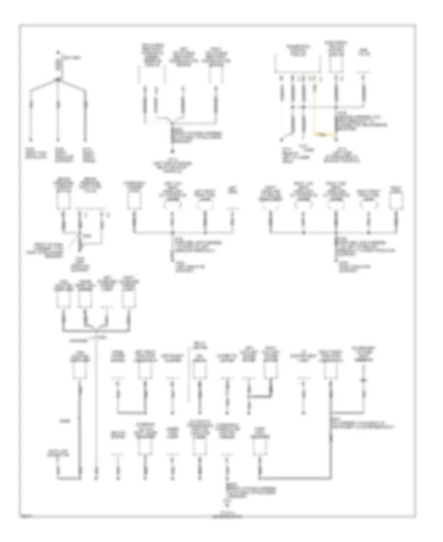
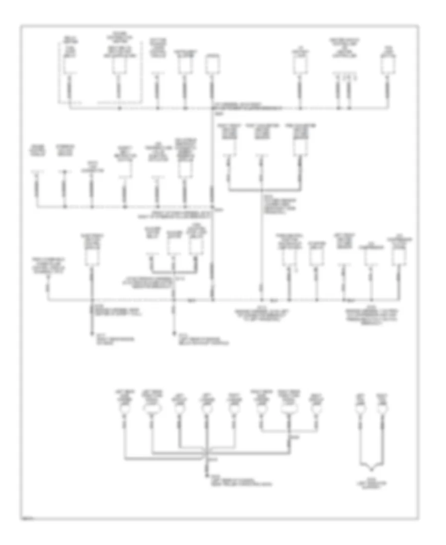
2.2L (VIN 4), Ground Distribution Wiring Diagram (2 of 2) for GMC Sonoma 1997
List of elements for 2.2L (VIN 4), Ground Distribution Wiring Diagram (2 of 2) for GMC Sonoma 1997:
- (engine harness, 20 cm from a/c compressor clutch breakout)
- A/c compressor
- A/c compressor clutch diode
- Air temperature valve electric actuator
- Blower motor
- Blower motor relay
- C4 a
- Cruise control module
- Data link connector
- Daytime running lamps control module
- Fog lamp switch
- From windshield wiper pulse control module (diagram 1 of 2)
- Fuel pump relay
- G108 (left radiator support)
- G112 (left side of engine, below exhaust manifold)
- G114 (left rear engine, below crank- shaft position sensor)
- G123 (right rear of eng. compartment)
- G416 (left rear of chassis, near trailer wiring provision)
- Heater and a/c controller or heater controller
- High mounted stop lamp relay
- I/p ashtray lamp
- Inflatable restraint diagnostic energy reserve module
- Instrument cluster
- Left
- Left backup lamp
- Left fog lamp
- Left rear park/turn signal lamp
- Left rear side marker lamp
- License lamp
- Park/neutral and backup lamp switch
- Post converter heated oxygen sensor
- Power distribution center
- Radio
- Relay center
- Right
- Right backup lamp
- Right fog lamp
- Right rear park/turn signal lamp
- Right rear side marker lamp
- S103
- S109 (engine harness, 6 cm from breakout to starter and compressor relays)
- S112
- S118 (i/p ext harn, 40 cm from breakout to blower motor resistors)
- S209 (i/p harness, 39 cm right of instrument cluster breakout)
- S244 (front of dash harness, 26 cm right of steering column breakout)
- S419
- S420
- Safety belt retractor switch
- Seat belts, ignition key and lamps alarm
- Starter relay
- Steering column ground
4.3L
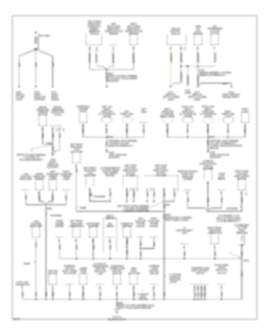
4.3L (VIN W), Ground Distribution Wiring Diagram (1 of 2) for GMC Sonoma 1997
List of elements for 4.3L (VIN W), Ground Distribution Wiring Diagram (1 of 2) for GMC Sonoma 1997:
- (cross body harness, right side of dash)
- (cut wire)
- (forward lamp harness, 7 cm right of left headlamp breakout)
- (front of dash harness, 17 cm right of bulkhead grommet)
- (i/p harness, 43 cm right of instrument cluster breakout)
- (left front door harness, 17 cm from crossbody harness connector)
- 7 cm left of breakout to right radiator support ground)
- A/c compressor cycling switch
- A/c request voltage drop resistor
- A12
- Automatic transmission position indicator lamp
- Base
- Battery
- Brake pressure modulator valve
- Brake pressure warning switch
- C10
- Cigarette lighter
- D10
- D12
- D13
- Data link connector
- Door lock relay
- Drl relay
- Four wheel drive indicator
- G108 (left radiator support)
- G109 (right radiator support)
- G114 (rear of left cylinder head)
- G117 (rear of right cylinder head)
- G118 (right front frame)
- G123 (right rear of engine compt)
- G125 (below water pump)
- High mounted stop lamp
- I/p compartment lamp
- Ignition switch
- Inflatable restraint diagnostic energy reserve module
- Inside rear view mirror
- Instrument cluster
- Interior lamps control module
- Interior lamps control module (w/o rke)
- Left auxiliary power outlet
- Left door lock and side window switch (w/ rke)
- Left door lock and side window switch (w/o rke)
- Left front side door jamb switch
- Left front side door lock actuator
- Left horn
- Left inflatable restraint discriminating sensor
- Left low beam headlamp (w/ composite lamps)
- Left park/turn lamp
- Left sunshade mirror lamp
- Mass air flow sensor
- Nca
- Non-base
- Outside remote control rear view mirror switch
- Panel dimmer switch
- Park pawl actuator
- Relay center
- Remote control door lock receiver (w/ rke)
- Right auxiliary power outlet
- Right door lock and side window switch
- Right front side door jamb switch
- Right headlamp (w/ sealed beam lamps)
- Right high beam headlamp (w/ composite lamps)
- Right horn
- Right inflatable restraint discriminating sensor
- Right low beam headlamp (w/ composite lamps)
- Right park/turn lamp
- Right sunshade mirror lamp
- S120
- S126
- S210
- S229
- S302
- Steering column shift lever actuator
- Switch
- To g114 (diagram 2 of 2)
- Transfer case shift control module
- Under- hood lamp
- Vehicle control module
- W/ decor level yc3/yc5
- W/ power windows and door locks
- Windshield washer pump
- Windshield wiper pulse control module
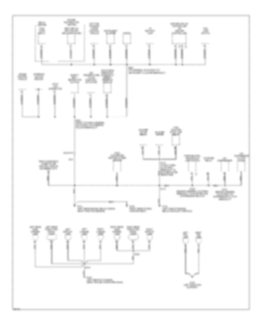
4.3L (VIN W), Ground Distribution Wiring Diagram (2 of 2) for GMC Sonoma 1997
List of elements for 4.3L (VIN W), Ground Distribution Wiring Diagram (2 of 2) for GMC Sonoma 1997:
- (front of dash harness, 26 cm right of steering column breakout)
- (i/p extension harness, s118
- (i/p harness, 39 cm right of instrument cluster breakout)
- 40 cm from blower motor resistor breakout)
- A/c compressor
- A/c compressor clutch diode
- Air temperature valve electric actuator
- Blower motor
- Blower motor relay
- C4 a
- Cruise control module
- Data link connector
- Daytime running lamps control module
- Electronic ignition control module
- Fog lamp switch
- From windshield wiper pulse control module (diagram 1 of 2)
- Fuel pump relay
- G108 (left radiator support)
- G114 (left rear of engine, below exhaust manifold)
- G117 (right rear engine, on head)
- G416 (left rear of chassis, near trailer wiring provision)
- Heater and a/c controller or heater controller
- High mounted stop lamp relay
- I/p ashtray lamp
- Inflatable restraint diagnostic energy reserve module
- Instrument cluster
- Left
- Left backup lamp
- Left fog lamp
- Left front heated oxygen sensor
- Left rear park/turn signal lamp
- Left rear side marker lamp
- License lamp
- Nca
- Park/neutral position and backup lamp switch
- Post converter heated oxygen sensor
- Power distribution center
- Pre converter heated oxygen sensor
- Radio
- Relay center
- Right
- Right backup lamp
- Right fog lamp
- Right front heated oxygen sensor
- Right rear park/turn signal lamp
- Right rear side marker lamp
- S103 (engine harness, 7 cm from a/c compressor and high pressure cutout switch breakout)
- S109 (engine harness, near center of safety wall)
- S112 (engine harness, 38 cm left of connector breakout to left frame rail)
- S209
- S244
- S318 (oxygen sensor jumper harn, near right side frame rail)
- S419
- S420
- Safety belt retractor switch
- Seat belts, ignition key and lamps alarm
- Starter relay
- Steering column ground
HEADLIGHTS
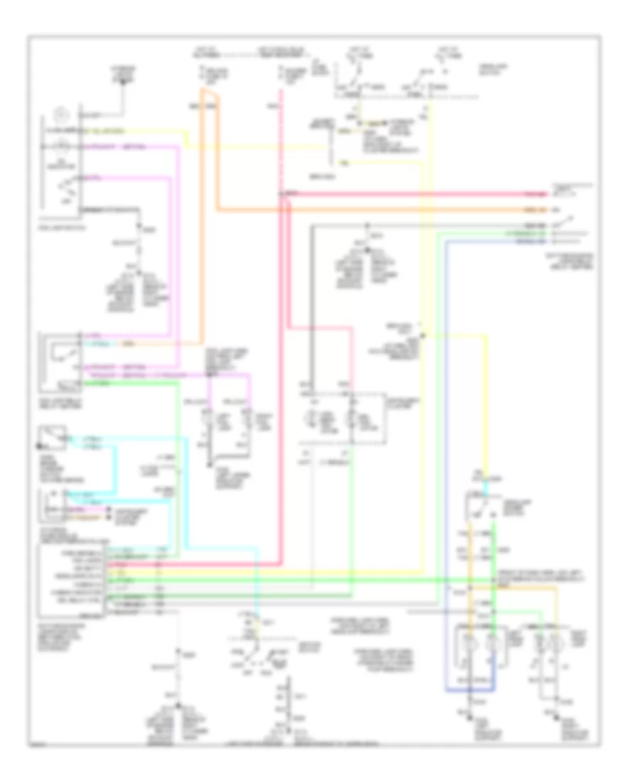
Headlight Wiring Diagram, with Composite Headlamps for GMC Sonoma 1997
List of elements for Headlight Wiring Diagram, with Composite Headlamps for GMC Sonoma 1997:
- (fog lamp harn, 4cm from left fog lamp breakout) s139
- (forward lamp harn, 13cm right of left headlamp breakout)
- (forward lamp harn, 4cm right of front windshield washer pump breakout)
- (front of dash harn, 4cm left of steering column breakout) s237
- (or tan)
- Acc
- B6 b6
- Bravada
- Bravada only
- Bulb test
- C206
- C211
- Daytime running lamps module (between hvac module and glove box)
- Daytime running lamps relay (relay center)
- Drl indi- cator
- Drl relay ctrl
- Drl/fog fuse 15 20a
- E11
- E12
- E13
- Except bravada
- Fog lamp relay (relay center)
- Fog lamp switch
- Fog lamps
- G108 (left radiator support)
- G108 (left upper radiator support)
- G109 (right radiator support)
- G112 (4 cyl.) (left side of engine below exhaust manifold)
- G112 (4 cyl.) (left side of engine)
- G114 (6 cyl.) (rear of right cylinder head)
- Gauges fuse 4 10a
- Ground
- Head
- Headlamp dimmer switch
- Headlamp switch
- Headlamps on in
- Hi-beam in
- Hi-beam indicator
- High beam indi- cator
- Hot at all times
- Hot in run, bulb test or start
- I/p fuse block
- I/p wiring diode module (above steering column)
- Ign (batt)
- Ignition switch
- Illum lamp
- Instrument cluster
- Instrument cluster system
- Interior lights system
- Left fog lamp
- Left head- lamp
- Lock
- Off
- On indicator
- Park
- Park brake in
- Park brake warning switch (on park brake)
- Pnk
- Right fog lamp
- Right head- lamp
- Run
- S120
- S121
- S124
- S126
- S202 (i/p harn, 6cm into headlamp sw breakout)
- S206 (i/p harn, 25cm right of cluster breakout)
- S209
- S210
- S213
- S230
- Start
- Tan
- W/ fog lamps
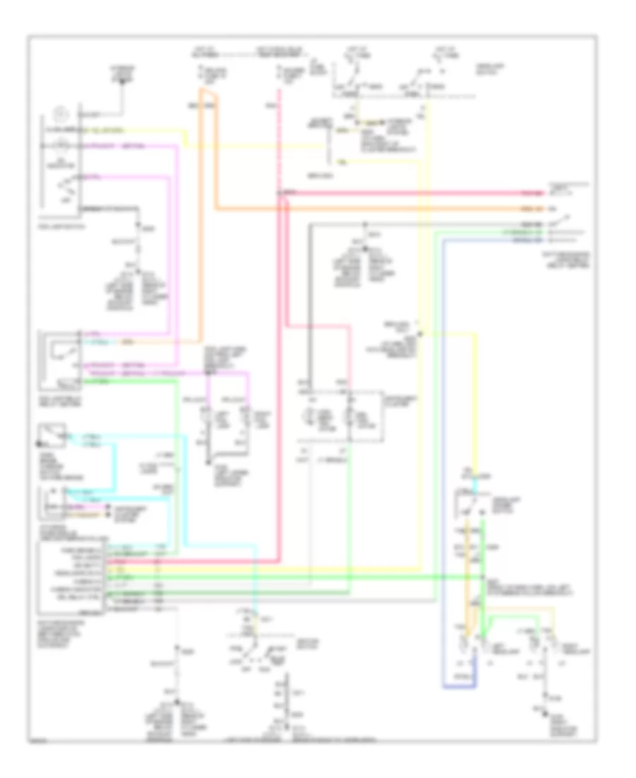
Headlight Wiring Diagram, with Sealed Beam Headlamps for GMC Sonoma 1997
List of elements for Headlight Wiring Diagram, with Sealed Beam Headlamps for GMC Sonoma 1997:
- (fog lamp harn, 4cm from left fog lamp breakout) s139
- (or tan)
- Acc
- B6 b6
- Bravada
- Bravada only
- Bulb test
- C206
- C211
- Daytime running lamps module (between hvac module and glove box)
- Daytime running lamps relay (relay center)
- Drl indi- cator
- Drl relay ctrl
- Drl/fog fuse 15 20a
- E11
- E12
- E13
- Except bravada
- Fog lamp relay (relay center)
- Fog lamp switch
- Fog lamps
- G108 (left upper radiator support)
- G109 (right radiator support)
- G112 (4 cyl.) (left side of engine below exhaust manifold)
- G112 (4 cyl.) (left side of engine)
- G114 (6 cyl.) (rear of right cylinder head)
- Gauges fuse 4 10a
- Ground
- Head
- Headlamp dimmer switch
- Headlamp switch
- Headlamps on in
- Hi-beam in
- Hi-beam indicator
- High beam indi- cator
- Hot at all times
- Hot in run, bulb test or start
- I/p fuse block
- I/p wiring diode module (above steering column)
- Ign (batt)
- Ignition switch
- Illum lamp
- Instrument cluster
- Instrument cluster system
- Interior lights system
- Left fog lamp
- Left headlamp
- Lock
- Off
- On indicator
- Park
- Park brake in
- Park brake warning switch (on park brake)
- Pnk
- Right fog lamp
- Right headlamp
- Run
- S126
- S202 (i/p harn, 6cm into headlamp sw breakout)
- S206 (i/p harn, 25cm right of cluster breakout)
- S209
- S210
- S213
- S230
- S237 (front of dash harn, 4cm left of steering column breakout)
- Start
- Tan
- W/ fog lamps
HORN
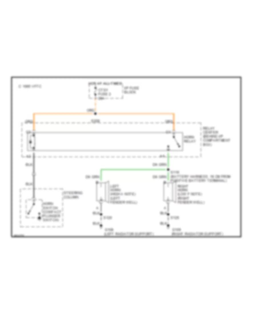
Horn Wiring Diagram for GMC Sonoma 1997
List of elements for Horn Wiring Diagram for GMC Sonoma 1997:
- C 1995 vftc
- Ctsy fuse 2 20a
- G108 (left radiator support)
- G109 (right radiator support)
- Horn relay
- Horn switch (contact plunger switch)
- Hot at all times
- I/p fuse block
- Left horn (high a note) (left fender well)
- Relay center (behind i/p compartment box)
- Right horn (low f note) (right fender well)
- S119 (battery harness, 18 cm from positive battery terminal)
- S120
- S126
- S208
- Steering column
INSTRUMENT CLUSTER
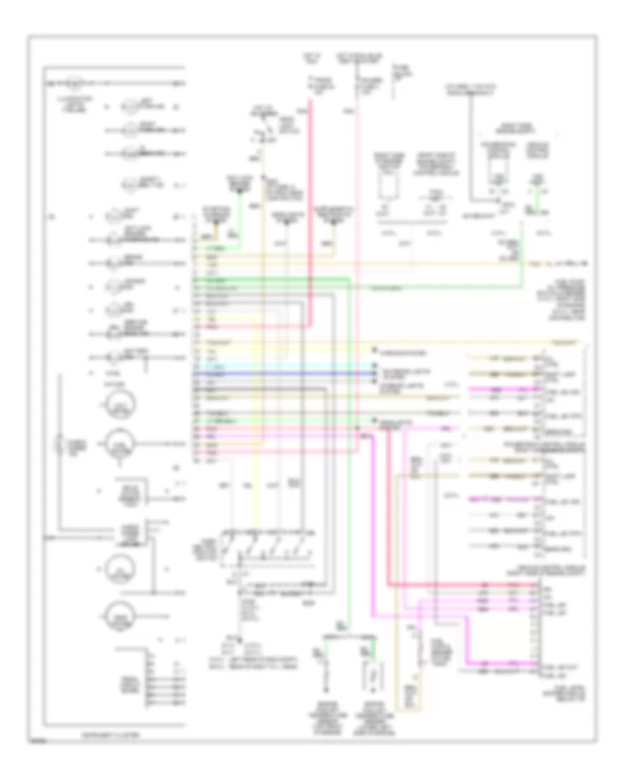
Instrument Cluster Wiring Diagram (1 of 2) for GMC Sonoma 1997
List of elements for Instrument Cluster Wiring Diagram (1 of 2) for GMC Sonoma 1997:
- (4 cyl)
- (6 cyl)
- (i/p harn, 7 cm into radio breakout)
- (mil)
- (right side engine compt)
- (right side of engine compt) powertrain control module
- (right side of engine) ignition coil
- +5v
- 4 cyl.
- 510 ohm
- 6 cyl.
- Air bag ind.
- Anti-lock brakes system
- Anti-lock brakes warning ind.
- Battery ind.
- Brake ind.
- Check gages ind.
- Check gages lamp driver
- Drl ind.
- Engine coolant temperature sender (lower left side of engine)
- Engine coolant temperature sensor (top front of engine)
- Exterior lights system
- Fuel gauge
- Fuel lev
- Fuel lev out
- Fuel lev rtn
- Fuel lev sig
- Fuel level buffer module (below i/p)
- Fuel pump & sender (in fuel tank)
- Fuel pump/ oil pressure switch & sender (4 cyl.-right side of engine) (6 cyl.-near distributor)
- Fuse block: i/p
- G114
- G117
- Gauges fuse 4 10a
- Head-
- Headlights
- Headlights system
- Hi beam ind.
- Hot at all times
- Hot in run
- Hot in run, bulb test or start
- Ign
- Illumination lights (7-bulbs)
- Instrument cluster
- Interior lights system
- Left rear of eng compt) (4-cyl
- Left turn ind.
- Light switch
- Mil ctrl
- Off
- Oil gauge
- Park/ neutral position switch
- Pnk
- Powertrain control module
- Powertrain control module (right side engine compt)
- Prndl circuit board
- Rear of right cyl. head) (6-cyl
- Right turn ind.
- S109 (4 cyl) s112 (6 cyl)
- S202 (i/p harn, 6 cm from head lamp switch)
- S209
- S210
- S212
- S213
- Safety belt ind.
- Sens gnd
- Service engine soon ind.
- Shift ind.
- Shift lamp ctrl
- Solid state speedo/ tach
- Starting/ charging system
- System
- Tach out
- Tan
- Temp gauge
- Trans fuse 24 10a
- Vehicle control module
- Vehicle control module (right side of engine compt)
- Volt meter
- Vss out
- Warning system
Instrument Cluster Wiring Diagram (2 of 2) for GMC Sonoma 1997
List of elements for Instrument Cluster Wiring Diagram (2 of 2) for GMC Sonoma 1997:
- (left side eng compt)
- 4 cyl.
- 6 cyl.
- A/t
- Acc
- Brake pressure modulator valve
- Brake pressure warning switch (left rear engine compt)
- Bulb check
- Bulb test
- Daytime running lights module (above steering column)
- Diode module (above steering column)
- G109 (right radiator support)
- G114 (left rear of engine, below ckp sensor)
- G117 (rear of right cylinder head)
- Ignition switch
- Liftgate release solenoid (inside endgate)
- Lock
- M/t
- Nca
- Off
- Park brake warning switch (at park brake pedal)
- Run
- S229
- S230
- S230 (front of dash harness, left rear of engine compt)
- Start
INTERIOR LIGHTS
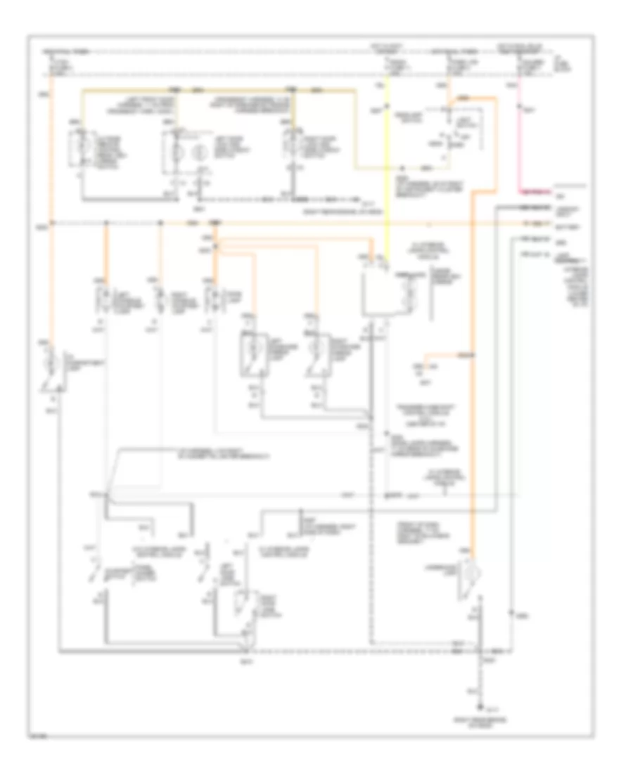
Courtesy Lamps Wiring Diagram for GMC Sonoma 1997
List of elements for Courtesy Lamps Wiring Diagram for GMC Sonoma 1997:
- (crossbody harness, 13 cm right of speaker extension harness breakout)
- (front of dash harness, 17 cm right of bulkhead grommet)
- (i/p harness, 4 cm right of cigarette lighter breakout)
- (left front door harness, 11 cm from crossbody harn. conn.)
- (lower center of i/p)
- (right rear engine, on head)
- B c2
- Bat
- Battery
- C c2
- Courtesy switch
- Ctsy fuse 2 20a
- Dome lamp
- F c1
- G117
- Gauges fuse 4 10a
- Grd
- Head
- Headlamp switch
- Hot at all times
- Hot in accy or run
- Hot in run, bulb test or start
- I/p compartment lamp
- I/p fuse block
- Ign
- Inside rearview mirror
- Interior lamps control module
- Jamb sw input
- Lamp control
- Left console courtesy lamp
- Left door jamb switch
- Left door lock and side window switch
- Left sunshade mirror lamp
- Light switch
- Map lamps
- Off
- Outside remote control rear view mirror switch
- Panel dimmer switch
- Park
- Park lps fuse 3 20a
- Pnk
- Radio fuse 11 20a
- Right console courtesy lamp
- Right door jamb switch
- Right door lock and side window switch
- Right sunshade mirror lamp
- S206 (i/p harness, 25 cm right of instrument cluster breakout)
- S207
- S208
- S210
- S214
- S230
- S241
- S242
- S249
- S261
- S262
- S279
- S297 (i/p harness, right side of dash)
- S300 (dome lamps harness, 71 cm rear of sunshade mirror breakout)
- S302
- S303
- S501
- S502
- Transfer case shift control module (4.3l) (center of i/p)
- Underhood lamp
- W/ interior lamps control module
- W/o interior lamps control module
Instrument Illumination Wiring Diagram for GMC Sonoma 1997
List of elements for Instrument Illumination Wiring Diagram for GMC Sonoma 1997:
- (3) bulbs
- (7) bulbs
- (i/p harness, 18 cm right of instrument cluster breakout) s205
- (left rear engine-below crankshaft sensor-2.2l, left of rear of engine-below exhaust manifold-4.3l)
- Automatic transmission position indicator lamp (floor shift a/t)
- Center
- Dim
- Display dim signal
- Drivers information display center (bravada)
- Endgate window release switch
- Exterior lights system, courtesy lamps circuit
- Fog lamp switch
- Four wheel driver indicator switch
- G114
- Ground
- Head
- Headlamp switch
- Headlights system
- Heater controller or heater and a/c controller
- High
- Hot at all times
- I/p ashtray lamp
- I/p fuse block
- Illum fuse 23 10a
- Instrument cluster
- Interior lights dim
- Interior lights feed
- Light switch
- Lights on input
- Nca
- Off
- Panel dimmer switch
- Park
- Pk lps fuse 3 20a
- Power distribution
- Power distribution system
- Prndl circuit board
- Radio
- Rear window defogger switch
- Rear window wiper and washer switch
- S206 (i/p harness, 25 cm right of instrument cluster breakout)
- S209
- S210
- S244
- S246
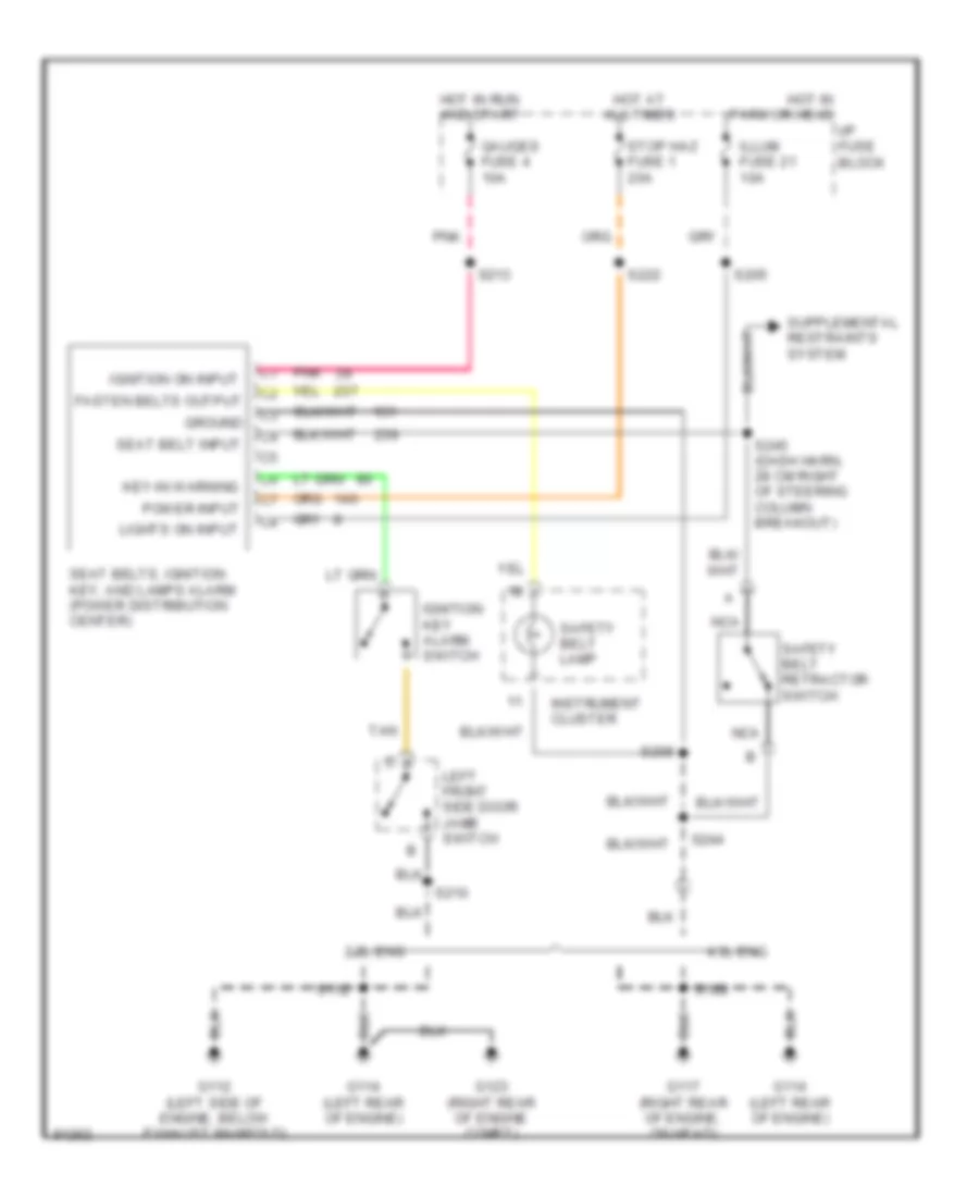
- Seat belts, ignition key and lamps alarm
POWER DISTRIBUTION
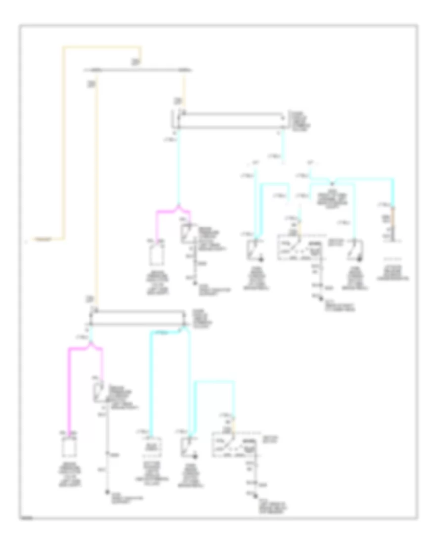
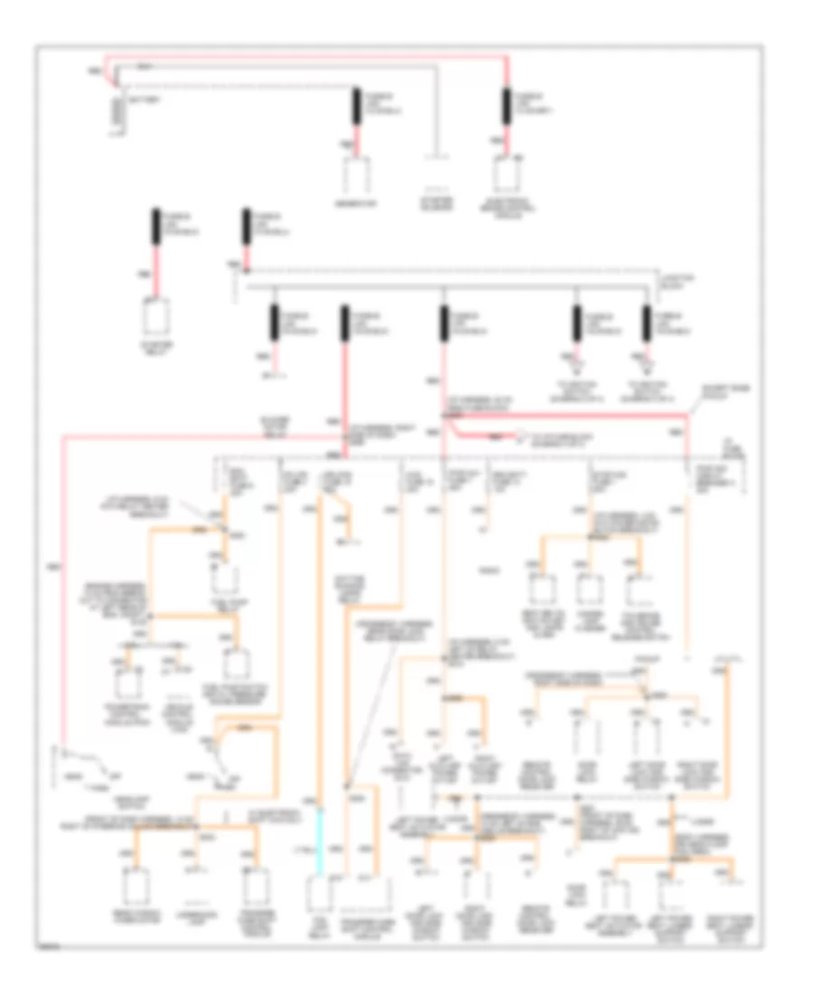
Power Distribution Wiring Diagram (1 of 4) for GMC Sonoma 1997
List of elements for Power Distribution Wiring Diagram (1 of 4) for GMC Sonoma 1997:
- (body harness, driver's floor pan area) s282
- (crossbody harness, near door lock relay breakout)
- (crossbody harness, right side of dash)
- (engine harness, 13 cm from break- out to connector at left rear of eng. compt.) s108
- (front of dash harness, 13 cm right of steering column breakout)
- (i/p harness, 20 cm from fuse block) s200
- (i/p harness, 4 cm into power distri- bution breakout) s222
- (i/p harness, 5 cm left of relay center breakout) s218
- (i/p harness, 6 cm into relay center breakout)
- (i/p harness, right side of dash) s299
- 2 door
- 2.2l
- 4 door
- 4.3l
- 4wd fuse 19 20a
- Battery
- Blower motor relay
- D14
- D15
- Data link connector (dlc)
- Daytime running lamps relay
- Door lock relay
- Drl/fog fuse 15 20a
- Ecm batt fuse 9 20a
- Electronic brake control module
- Except base pickup
- Fog lamp relay
- Fuel pump relay
- Fuel pump switch and oil pressure gauge sensor
- Generator
- Hazard lamp flasher
- Head
- Headlamp switch
- I/p fuse block
- Junction block
- Left auxiliary power outlet
- Left door lock and side window switch
- Left power seat actuator assembly
- Left power seat lumbar support switch
- Off
- Park
- Pickup
- Pk lps fuse 3 20a
- Powertrain control module (pcm)
- Pwr acc circuit breaker a 30a
- Pwr aux fuse 7 25a
- Radio
- Rdo batt fuse 13 10a
- Rear window wiper motor
- Red
- Remote control door lock receiver
- Right auxiliary power outlet
- Right door lock and side window switch
- Right power seat lumbar support switch
- S220
- S242
- S251 (front of dash harness, 29 cm right of 4wd ind. breakout)
- S253
- S263
- S268
- Seat belts, ignition key and lamps alarm
- Starter relay
- Starter solenoid
- Stop-haz fuse 1 20a
- Tcc brake and cruise control release switch
- To i/p fuse block (diagram 4 of 4)
- To ignition switch (diagram 2 of 4)
- To ignition switch (diagram 3 of 4)
- Transfer case shift control module
- Underhood lamp
- Utility
- Vehicle control module (vcm)
- W/ electronic shift 4wd only
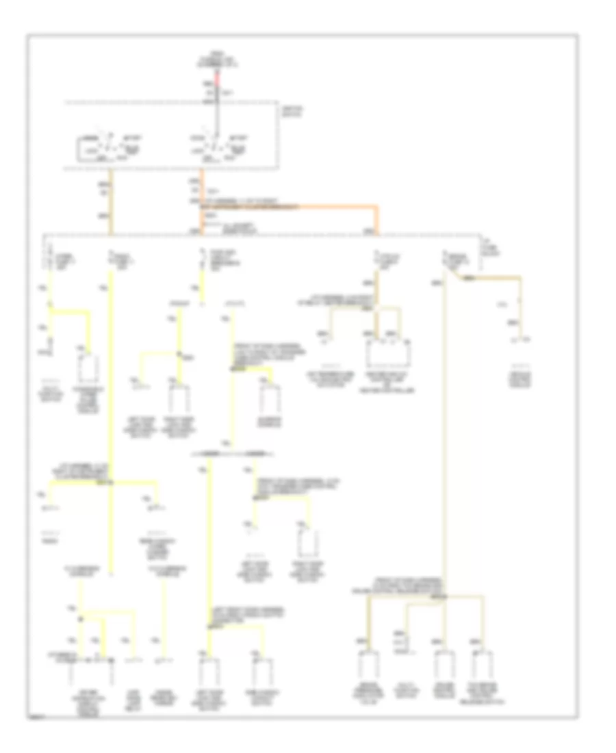
Power Distribution Wiring Diagram (2 of 4) for GMC Sonoma 1997
List of elements for Power Distribution Wiring Diagram (2 of 4) for GMC Sonoma 1997:
- (front of dash harness, 13 cm into transfer case control module breakout) s254
- (front of dash harness, 18 cm from tcc brake and cruise control release switch) s239
- (front of dash harness, 4 cm to right of transfer case control module breakout) s255
- (i/p harness, 31 cm right of instrument cluster breakout) s207
- (i/p harness, 5 cm right of relay center breakout) s221
- (left front door harness, 19 cm from window switch connector) s503
- (olds) d
- (others) b
- 2 door
- 20a
- 4 door
- 4.3l
- A13
- Accy
- Air temperature valve electric actuator
- All except base pickup
- Block
- Brake fuse 12 10a
- Brake pressure modulator valve
- Bulb test
- C211
- Cruise control module
- Driver information display control module
- From fusible link (diagram 1 of 4)
- Heater and a/c controller or heater controller
- Htr a/c fuse 6 20a
- I/p fuse
- Ignition
- Inside rearview mirror
- Left door lock and side window switch
- Lock
- Map/ dome lamp relay
- Multi- function switch
- Nca
- Off
- Pickup
- Pwr wdo circuit breaker b 30a
- Radio
- Radio fuse 11
- Rear window wiper/ washer switch
- Red
- Right door lock and side window switch
- Run
- S204
- S254
- Side window lockout switch
- Start
- Sunroof console
- Switch
- Tcc brake and cruise control release switch
- Utility
- Vehicle control module
- W/ overhead console
- W/o overhead console
- Windshield wiper pulse control module
- Wiper fuse 17 25a
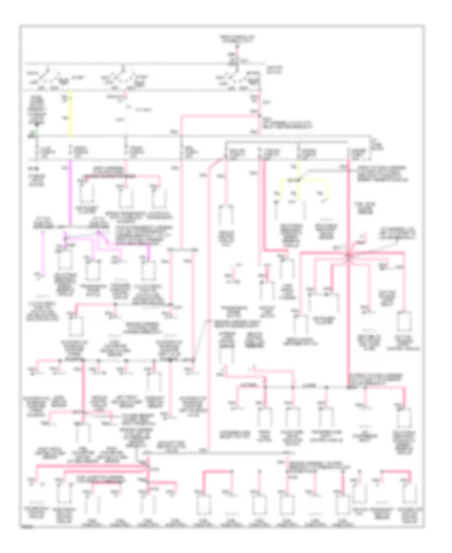
Power Distribution Wiring Diagram (3 of 4) for GMC Sonoma 1997
List of elements for Power Distribution Wiring Diagram (3 of 4) for GMC Sonoma 1997:
- (body harness, 74 cm from dash harness connector) s266
- (engine harness, 12 cm left of a/c pressure sensor breakout)
- (engine harness, 15 cm from dash harness breakout)
- (engine harness, 7 cm from breakout to steering column connector)
- (engine harness, right rear of engine compt)
- (front of dash harness, 3 cm from inflatable restraint diagnostic energy reserve module)
- (fuel injector harness, 3 cm from inj 3 breakout) c3
- (i/p harness, 4 cm left of cigarette lighter breakout)
- (in front of dash harness, 6 cm to right of steering column breakout) s241
- (interior lights system)
- (oxygen sensor jumper, near right frame rail)
- (pickup-crossbody harness, 4 cm left of speaker ext. harness breakout, utility- front of dash harness, 45 cm from derm conn.)
- 2.2l
- 4.3l
- A/c compressor relay
- A/t
- A/t only
- A10
- Accy
- Air bag fuse 22 10a
- Automatic transmission
- B10
- Backup lamp switch
- Brake transmission shift interlock solenoid
- Bulb test
- C211
- Camshaft position sensor
- Clutch pedal position switch and cruise control shutoff switch
- Crank fuse 20 10a
- Crankshaft position sensor
- D16
- D5 nca
- Daytime running lamps control module
- Daytime running lamps relay
- Distributor ignition control module
- Ecm ign fuse 10 20a
- Electronic ignition control module
- Eng fuse 5 20a
- Evaporative emissions canister purge solenoid
- Evaporative emissions canister vent solenoid valve
- Evaporative emissions canister vent valve solenoid
- Exhaust gas recirculation valve
- Four-wheel drive indicator switch
- From fusible link (diagram 1 of 4)
- Front axle switch
- Fuel injector 1
- Fuel injector 2
- Fuel injector 3
- Fuel injector 4
- Fuel injector 5
- Fuel injector 6
- Fuel level buffer module
- Gauges fuse 4 10a
- I/p fuse block
- Ignition coil
- Ignition switch
- Illum fuse 23 10a
- Inflatable restraint arming sensor
- Inflatable restraint diagnostic energy reserve module
- Instrument cluster
- Interior lamps control module
- Interior lights system
- Left front heated oxygen sensor
- Lock
- M/t
- M/t w/ electric shift 4wd
- M/t w/o electric shift 4wd
- Mass airflow sensor
- Off
- Panel dimmer switch assembly
- Pnk
- Pnk a
- Pnk b
- Pnk b2
- Pnk c5
- Pnk c6
- Pnk d
- Pnk e
- Pnk f
- Post converter heated oxygen sensor
- Post- converter heated oxygen sensor
- Powertrain control module
- Pre- converter heated oxygen sensor
- Rear window defogger switch
- Red
- Remote control door lock receiver
- Right front heated oxygen sensor
- Run
- S105
- S107
- S128
- S213
- S219
- S219 (i/p harness, 8-13 cm into relay center breakout)
- S317
- Seat belts, ignition key and lamps alarm
- Start
- Trans fuse 24 10a
- Transfer case select switch
- Transfer case shift control module
- Transmission range switch
- Turn b/u fuse 16 15a
- Turn signal lamp flasher
- Vehicle control module (4.3l)
- Vehicle control module (vcm)
- W/ rke
- W/o rke
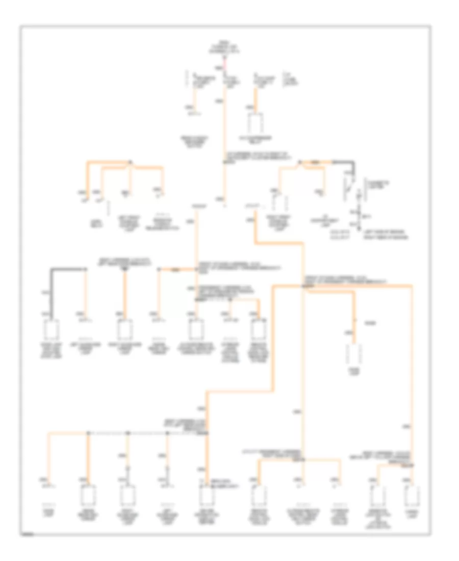
Power Distribution Wiring Diagram (4 of 4) for GMC Sonoma 1997
List of elements for Power Distribution Wiring Diagram (4 of 4) for GMC Sonoma 1997:
- (2.2l) g112
- (4.3l) g117
- (blazer/jimmy)
- (body harness, 13-34 cm above left taillamp harness breakout) s403
- (body harness, 8 cm into left rear door breakout) s303
- (bravada)
- (front of dash harness, 15 cm right of crossbody harness breakout) s249
- (i/p harness, 35 cm to right of instrument cluster breakout) s208
- (left side of engine)
- (right rear of engine)
- (utility crossbody harness, right side of dash) s257
- A/c comp fuse 14 10a
- A/c compressor relay
- Base
- Cargo lamp
- Cigarette lighter
- Ctsy fuse 2 20a
- Dome lamp
- Dome lamp and high mounted stop lamp
- Driver information display center
- Endgate lock switch or liftgate lock switch
- Endgate window release switch
- From fusible link (diagram 1 of 4)
- Horn relay
- I/p compartment lamp
- I/p fuse block
- Inside rear view mirror
- Inside rearview mirror
- Interior lamps control module
- Interior lamps control module (w/o rke)
- Left front console courtesy lamp
- Left of speaker extension harness breakout) s257
- Left sunshade mirror lamp
- Nca
- Outside remote control rear- view mirror switch
- Outside remote control rearview mirror switch
- Pickup
- Rear window defogger switch
- Red
- Remote control door lock module
- Remote control door lock receiver (w/ rke)
- Right front console courtesy lamp
- Right sunshade mirror lamp
- Rr defog fuse 8 30a
- S210
- Utility
POWER DOOR LOCKS
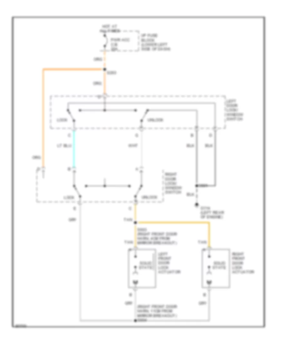
Door Lock Wiring Diagram for GMC Sonoma 1997
List of elements for Door Lock Wiring Diagram for GMC Sonoma 1997:
- (right front door harn, 11cm from mirror breakout) s604
- G114 (left rear of engine)
- Hot at all times
- I/p fuse block (lower left side of dash)
- Left door lock/ window switch
- Left front door lock actuator
- Lock
- Pwr acc c.b. 20a
- Right door lock/ window switch
- Right front door lock actuator
- S263
- S501
- S603 (right front door harn, 4cm from mirror breakout)
- Solid state
- Tan
- Unlock
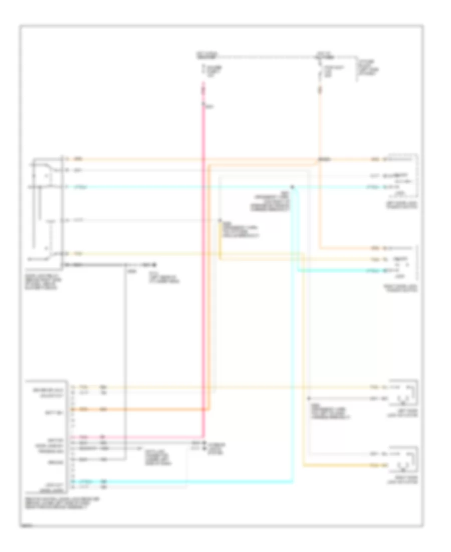
Keyless Entry Wiring Diagram for GMC Sonoma 1997
List of elements for Keyless Entry Wiring Diagram for GMC Sonoma 1997:
- Batt (b+)
- Data link connector (under left side of dash)
- Dome lamps
- Door jamb sw
- Door lock relay (behind right side of dash, above blower plenum)
- Driver dr unlk
- G114 (left rear of cylinder head)
- Gauges fuse 4 10a
- Ground
- Hot at all times
- Hot in run, or start
- I/p fuse block (left side of dash)
- Ignition
- Interior lights system
- Left door lock actuator
- Left door lock/ window switch
- Lock
- Lock out
- Pnk
- Program sig
- Pwr accy c.b. 20a
- Remote control door lock receiver (behind lower left side of dash, near parking brake assembly)
- Right door lock actuator
- Right door lock/ window switch
- S241
- S256 (crossbody harn, 7cm into rke module breakout)
- S262
- S263
- S264 (crossbody harn, 7cm left of dash harness breakout)
- S281 (crossbody harn, 13cm right of speaker extension harness breakout)
- Tan
- Unlock
- Unlock out
POWER MIRRORS
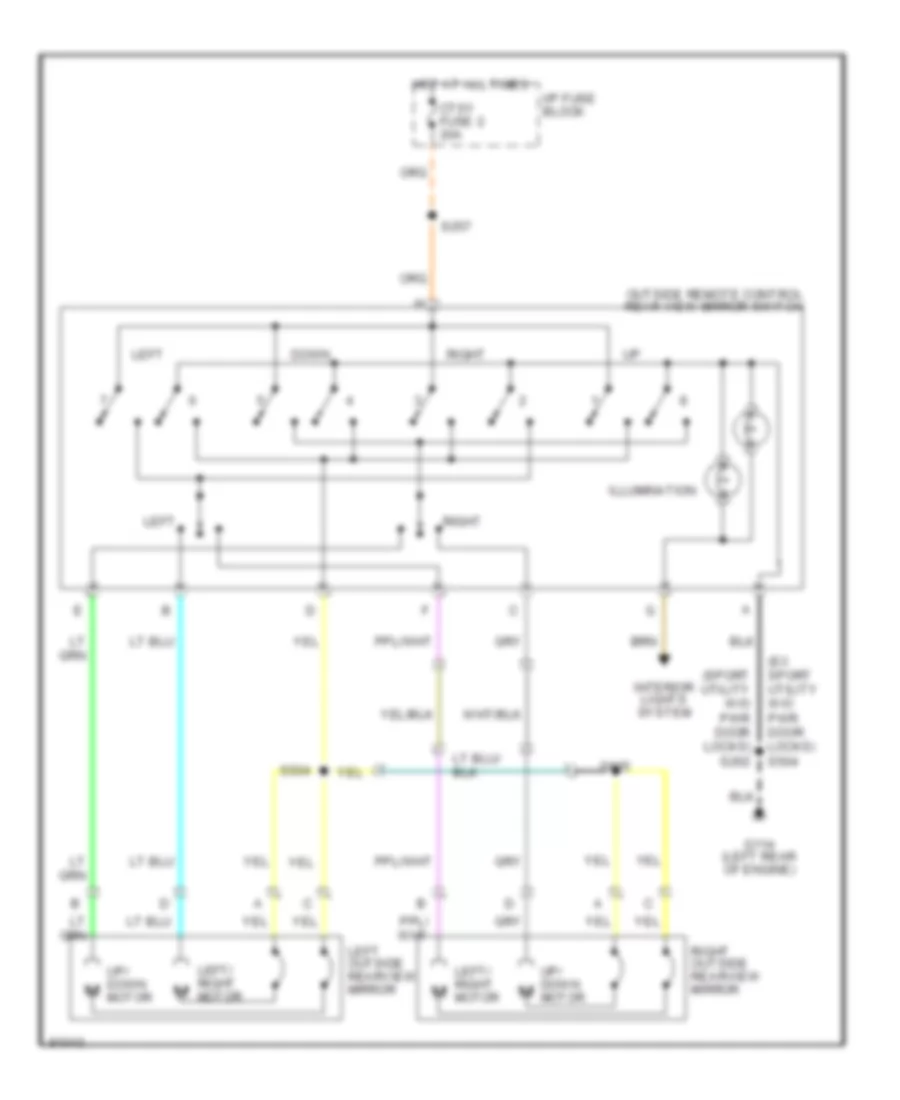
Power Mirror Wiring Diagram for GMC Sonoma 1997
List of elements for Power Mirror Wiring Diagram for GMC Sonoma 1997:
- (ex sport utility w/o pwr door locks) s504
- (sport utility w/o pwr door locks) s262
- Ctsy fuse 2 20a
- Down
- G114 (left rear of engine)
- Hot at all times
- I/p fuse block
- Illumination
- Interior lights system
- Left
- Left outside rearview mirror
- Left/ right motor
- Motor
- Outside remote control rear view mirror switch
- Right
- Right outside rearview mirror
- S257
- S504
- S605
- Up/ down m
POWER WINDOWS
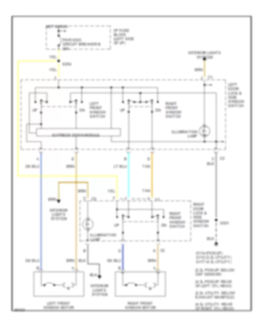
Power Window Wiring Diagram, 2 Door for GMC Sonoma 1997
List of elements for Power Window Wiring Diagram, 2 Door for GMC Sonoma 1997:
- (2.2l pickup: below ckp sensor)
- (2.2l utility: below exhaust manifold)
- (4.3l pickup: rear of left cyl head)
- (4.3l utility: rear of right cyl head)
- C2 k
- Express down module
- G114 (pickup) g112 (2.2l utility) g117 (4.3l utility)
- Hot in run
- I/p fuse block (left side of i/p)
- Illumination lamp
- Interior lights system
- Left door lock & side window switch
- Left front window motor
- Left front window switch
- Pwr wdo circuit breaker b 30a
- Right door lock & side window switch
- Right front window motor
- Right front window switch
- S254
- S501
- Tan
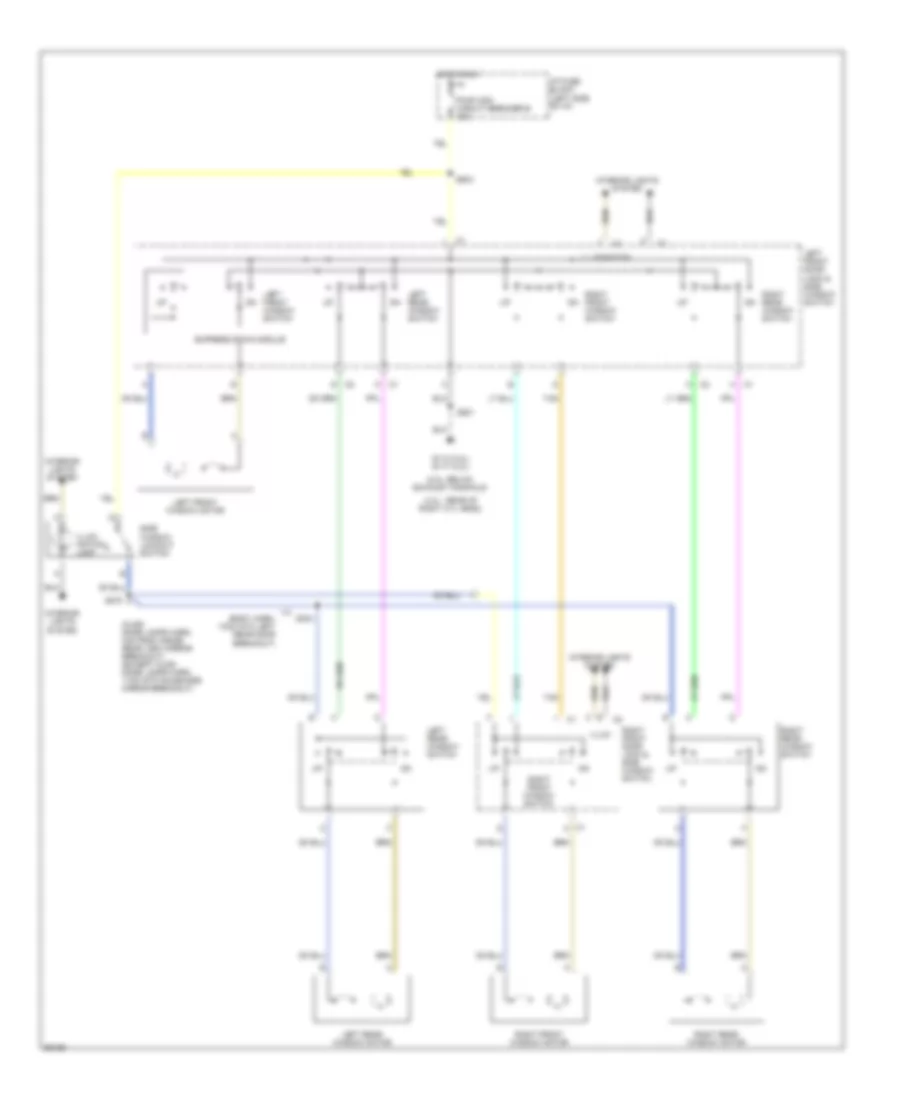
Power Window Wiring Diagram, 4 Door for GMC Sonoma 1997
List of elements for Power Window Wiring Diagram, 4 Door for GMC Sonoma 1997:
- (2.2l: below exhaust manifold)
- (4.3l: rear of right cyl head)
- (body harn, 13cm into left rear door breakout)
- (olds: dome lamps harn, 4cm from inside rear view mirror breakout) (except olds: dome lamps harn, 11cm into sunshade mirror breakout)
- C1 k
- Express down module
- G112 (2.2l) g117 (4.3l)
- Hot in run
- I/p fuse block (left side of i/p)
- Illum
- Illum- ination lamp
- Illumination
- Interior lights system
- Left front door lock & side window switch
- Left front window motor
- Left front window switch
- Left rear window motor
- Left rear window switch
- Pwr wdo circuit breaker b 30a
- Right front door lock & side window switch
- Right front window motor
- Right front window switch
- Right rear window motor
- Right rear window switch
- S278
- S304
- S501
- S503
- Side window lockout switch
- Tan
RADIO
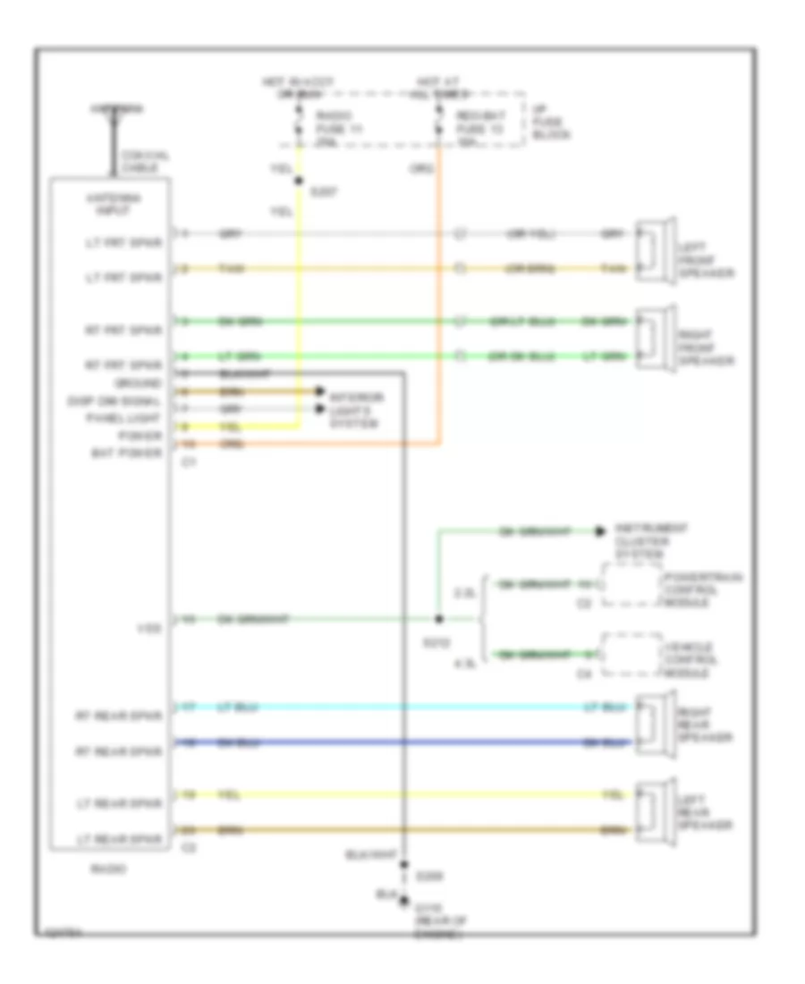
Radio Wiring Diagrams for GMC Sonoma 1997
List of elements for Radio Wiring Diagrams for GMC Sonoma 1997:
- 2.2l
- 4.3l
- Antenna
- Antenna input
- Bat power
- Coaxial cable
- Disp dim signal
- G115 (rear of engine)
- Ground
- Hot at all times
- Hot in accy or run
- I/p fuse block
- Instrument cluster system
- Interior lights system
- Left front speaker
- Left rear speaker
- Lt frt spkr
- Lt rear spkr
- Panel light
- Power
- Powertrain control module
- Radio
- Radio fuse 11 20a
- Rdo-bat fuse 13 10a
- Right front speaker
- Right rear speaker
- Rt frt spkr
- Rt rear spkr
- S207
- S209
- S212
- Tan
- Vehicle control module
- Vss
SHIFT INTERLOCKS
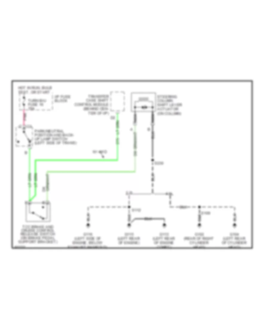
Shift Interlock Wiring Diagram for GMC Sonoma 1997
List of elements for Shift Interlock Wiring Diagram for GMC Sonoma 1997:
- 2.2l
- 4.3l
- G102 (rear of right cylinder head)
- G104 (left rear of cylinder head)
- G113 (left rear of engine compt)
- G115 (left rear of engine)
- G116 (left side of engine, below exhaust manifold)
- Hot in run, bulb test, or start
- I/p fuse block
- Nca
- Park/neutral position and back- up lamp switch (left side of trans)
- Pnk
- S109
- S112
- S230
- Steering column shift lever actuator (on column)
- Tcc brake and cruise control release switch (on brake pedal support bracket)
- Transfer case shift control module (behind cen- ter of i/p)
- Turn b/u fuse 16 15a
- W/ 4wd
STARTING/CHARGING
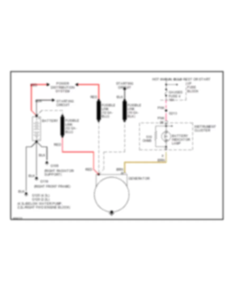
Charging Wiring Diagram for GMC Sonoma 1997
List of elements for Charging Wiring Diagram for GMC Sonoma 1997:
- (4.3l-below water pump, 2.2l-right fwd engine block)
- (right front frame)
- (right radiator support)
- Battery
- Battery indicator lamp
- G109
- G118
- G125 (4.3l) g120 (2.2l)
- Gauges fuse 4 10a
- Generator
- Hot in run, bulb test or start
- I/p fuse block
- Instrument cluster
- Ohms
- Pnk
- Power distribution system
- Red
- S213
- Starting circuit
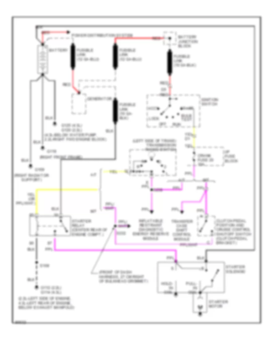
Starting Wiring Diagram for GMC Sonoma 1997
List of elements for Starting Wiring Diagram for GMC Sonoma 1997:
- (2.2l-left side of engine, 4.3l-left rear of engine, below exhaust manifold)
- (front of dash harness, 27 cm right of bulkhead grommet)
- (left side of trans) transmission range switch
- (right front frame)
- (right radiator support)
- A/t
- Accy
- Battery
- Battery junction block
- Bulb test
- Clutch pedal position and cruise control shutoff switch (clutch pedal bracket)
- Crank fuse 20 10a
- G109
- G112 (2.2l) g114 (4.3l)
- G118
- G125 (4.3l) g120 (2.2l)
- Generator
- Hold- in coil
- I/p fuse block
- Ignition switch
- Inflatable restraint diagnostic energy reserve module
- Lock
- M/t
- Off
- Power distribution system
- Pull- in coil
- Red
- Run
- S109
- S232
- S258
- Start
- Starter motor
- Starter relay (center rear of engine compt.)
- Starter solenoid
- Transfer case shift control module
SUPPLEMENTAL RESTRAINTS
Supplemental Restraint Wiring Diagram for GMC Sonoma 1997
List of elements for Supplemental Restraint Wiring Diagram for GMC Sonoma 1997:
- (806)
- (dash harn, near breakout to airbag mod) s260
- (dash harn, near grommet at left rear of eng compt) s233
- A/t
- A10
- A11
- A12
- Air bag fuse 22 10a
- Air bag warning lamp
- Arming sensor (left side frame rail, near center crossmember)
- B10
- B11
- B12
- Clutch pedal position switch (on pedal support)
- Crank fuse 20 10a
- Crank input
- Data link connector (behind left side of i/p)
- Diagnostic energy reserve module (derm) (behind right kick panel)
- Diagnostic requst in
- Driver 36 vlr
- Driver sense high
- Driver sense low
- Driver source sense
- G112 (left side of engine)
- G114 (left rear of engine)
- Gauges fuse 4 10a
- Ground
- Hot in run, bulb test or start
- Hot in start
- I/p fuse block
- Ignition
- Instrument cluster
- Left forward discriminating sensor (left side of lower radiator support)
- M/t
- Nca
- Pnk
- Redundant indic, ign
- Right forward discriminating sensor (right side of lower radiator support)
- S213 (i/p harn, near breakout to cigar lighter)
- S232 (dash harn, near grommet at left rear of eng compt)
- S244 (dash harn, right of steering column)
- S245 (dash harn, right of steering column)
- Safety belt switch
- Seat belt monitor
- Shorting bar
- Sir coil assembly (top of steering column)
- Sir indic low
- Starting/charging system (starter relay)
- Steering wheel inflator module (mounted on steering wheel)
- Tan
- Warning systems (audio alarm)
TRANSMISSION
2.2L
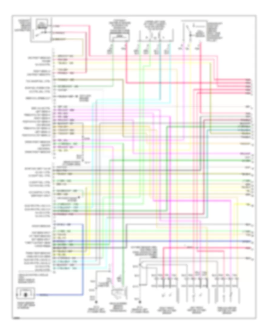
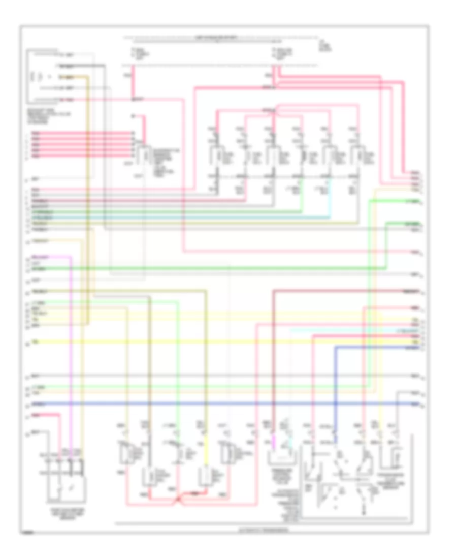
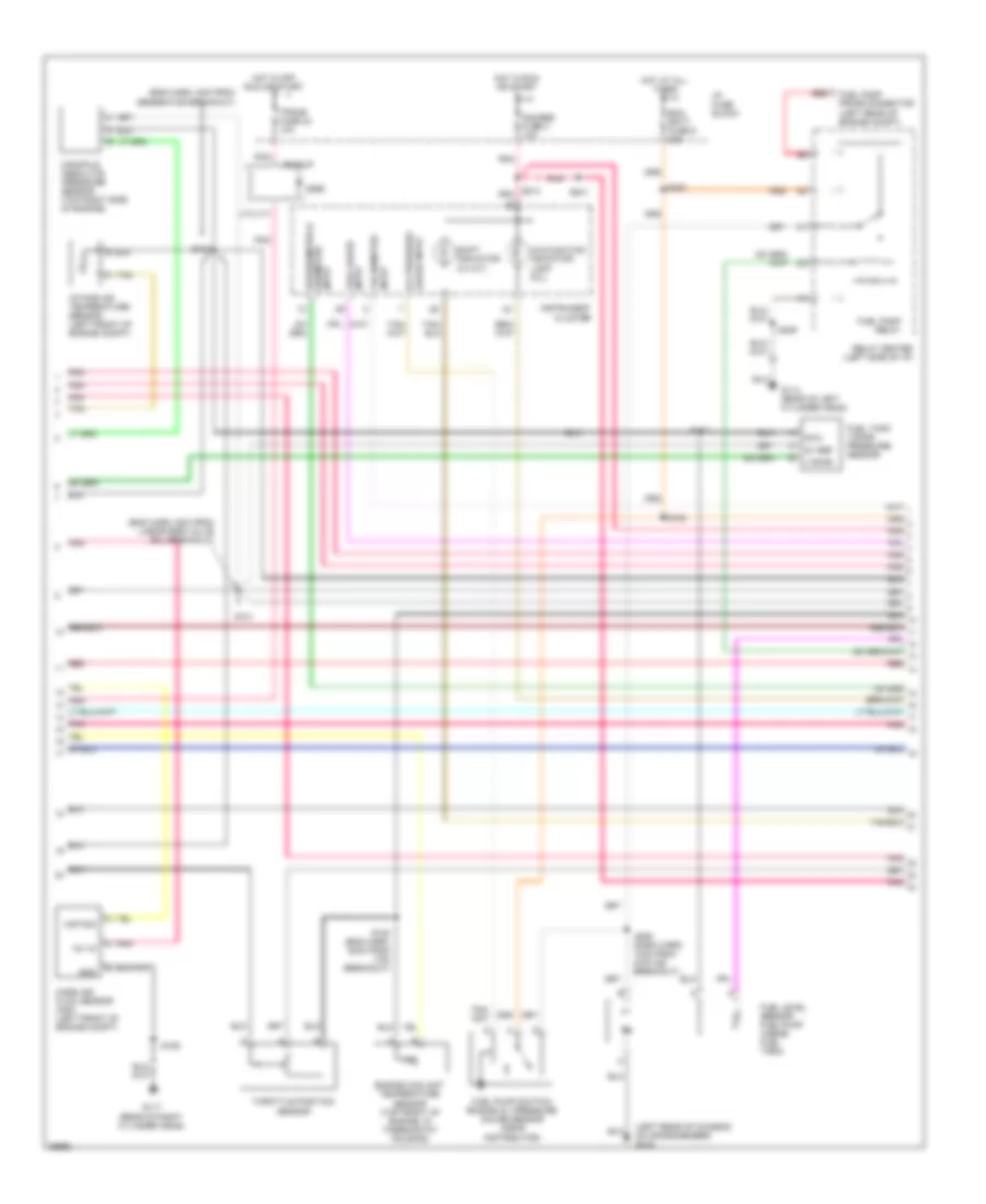
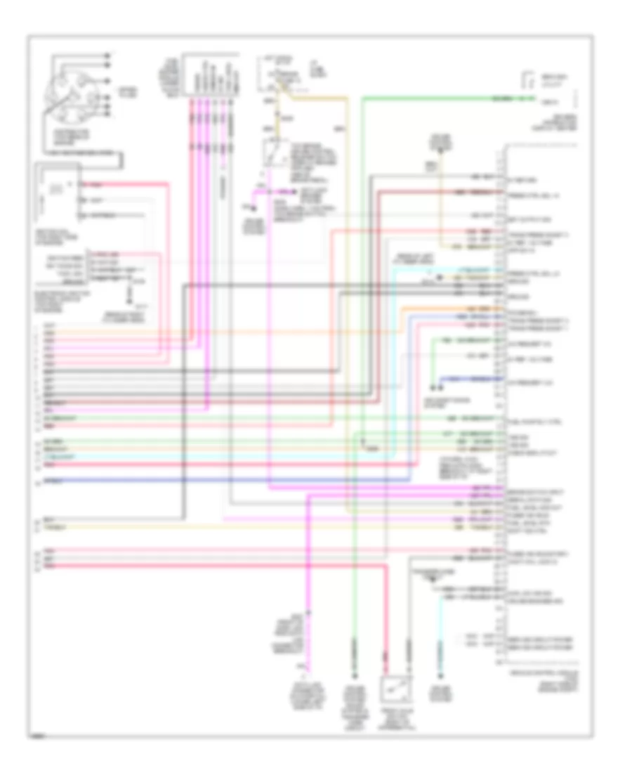
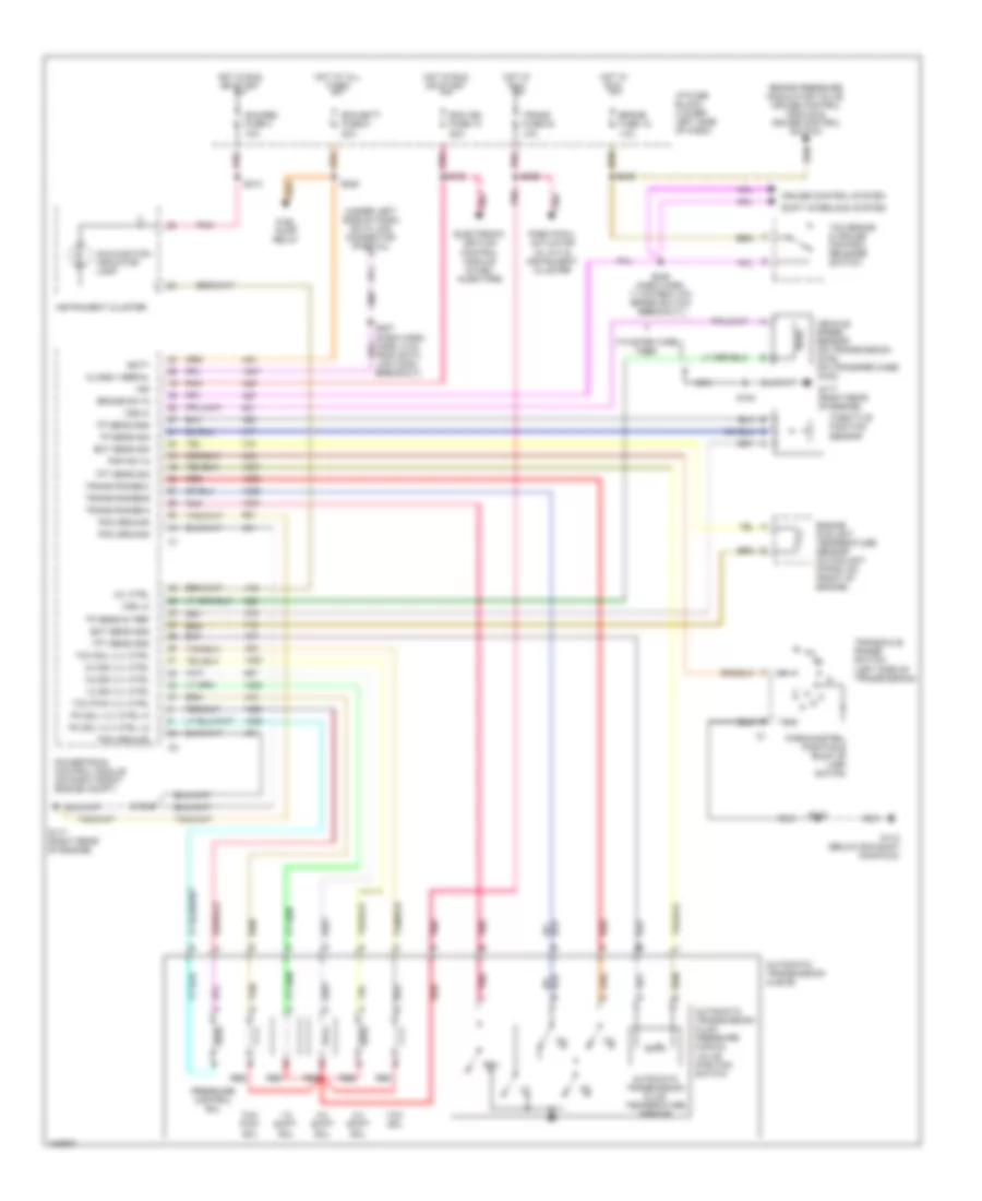
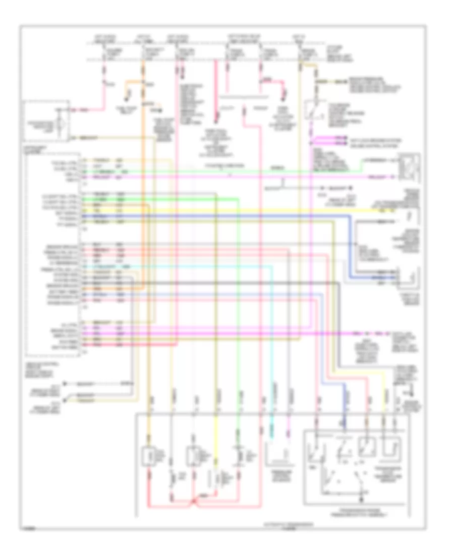
2.2L (VIN 4), Transmission Wiring Diagram, 4L60-E for GMC Sonoma 1997
List of elements for 2.2L (VIN 4), Transmission Wiring Diagram, 4L60-E for GMC Sonoma 1997:
- (twisted wire pair)
- (under left side of dash) data link connector (partial)
- 1-2 shift sol
- 1-2 ss vlv ctrl
- 2-3 shift sol
- 2-3 ss vlv ctrl
- 3-2 shift sol
- 3-2 ss vlv ctrl
- Automatic transmission (4l60-e)
- Automatic transmission fluid pressure manual valve position switch
- Automatic transmission fluid temperature sensor
- Batt
- Brake fuse 12 10a
- Brake pressure modulator valve, cruise control module & cruise control switch
- Brake sw in
- Class ii serial
- Cruise control system
- Ecm batt fuse 9 20a
- Ecm ign fuse 10 20a
- Ect sens gnd
- Ect sens sig
- Electronic ignition control module & fuel injectors
- Engine coolant temperature sensor (in coolant piping, on front of engine)
- Fuel pump relay
- G112 (below exhaust manifold)
- G117 (right rear of engine)
- Gauges fuse 4 10a
- Gnd
- Hot at all times
- Hot in run
- Hot in run or start
- I/p fuse block (lower left side of dash)
- Ign
- Instrument cluster
- Malfunction indicator lamp
- Mil ctrl
- Nca
- Park pawl actuator (w/ a/t) & instrument cluster
- Park/nuetral position & back up lamp switch
- Pc sol vlv ctrl hi
- Pc sol vlv ctrl lo
- Pcm ground
- Pnk
- Pnp sw in
- Powertrain control module (on right front engine compt)
- Pressure control sol
- Red
- Rev
- S105
- S106
- S112
- S140
- S213
- S220
- S227 (dash harn, harn, 8 cm from data link conn breakout)
- S238 (dash harn, 11 cm from tcc brake switch breakout)
- S239
- S266
- Shift interlock system
- Tan
- Tcc brake & cruise control release switch
- Tcc pwm sol
- Tcc pwm vlv ctrl
- Tcc sol
- Tcc sol vlv ctrl
- Tft sens gnd
- Tft sens sig
- Throttle position sensor
- Tp sens 5v ref
- Tp sens gnd
- Tp sens sig
- Trans fuse 24 10a
- Trans range-a
- Trans range-b
- Trans range-c
- Transaxle range switch (left side of transmission)
- Vehicle speed sensor (on transmission -2wd) (on transfer case -4wd)
- Vss hi
- Vss lo
Electronic Transfer Case Wiring Diagram for GMC Sonoma 1997
List of elements for Electronic Transfer Case Wiring Diagram for GMC Sonoma 1997:
- (a/t only)
- (a/t) 4wd lo selected
- (a/t) pnp switch in (p)
- (dash harn, 20 cm from breakout of 23-pin conn behind right side of dash) s259
- (m/t only)
- (w/ m/t only)
- 12v battery
- 12v ignition
- 2 hi request
- 2 hi status lamp
- 2wd hi indicator
- 2wd hi switch
- 4 hi request
- 4 hi status lamp
- 4 lo request
- 4 lo status lamp
- 4wd fuse 19 20 a
- 4wd hi indicator
- 4wd hi switch
- 4wd lo in
- 4wd lo indicator
- 4wd lo switch
- A/c compressor relay & inflatable restraint diagnostic energy reserve module
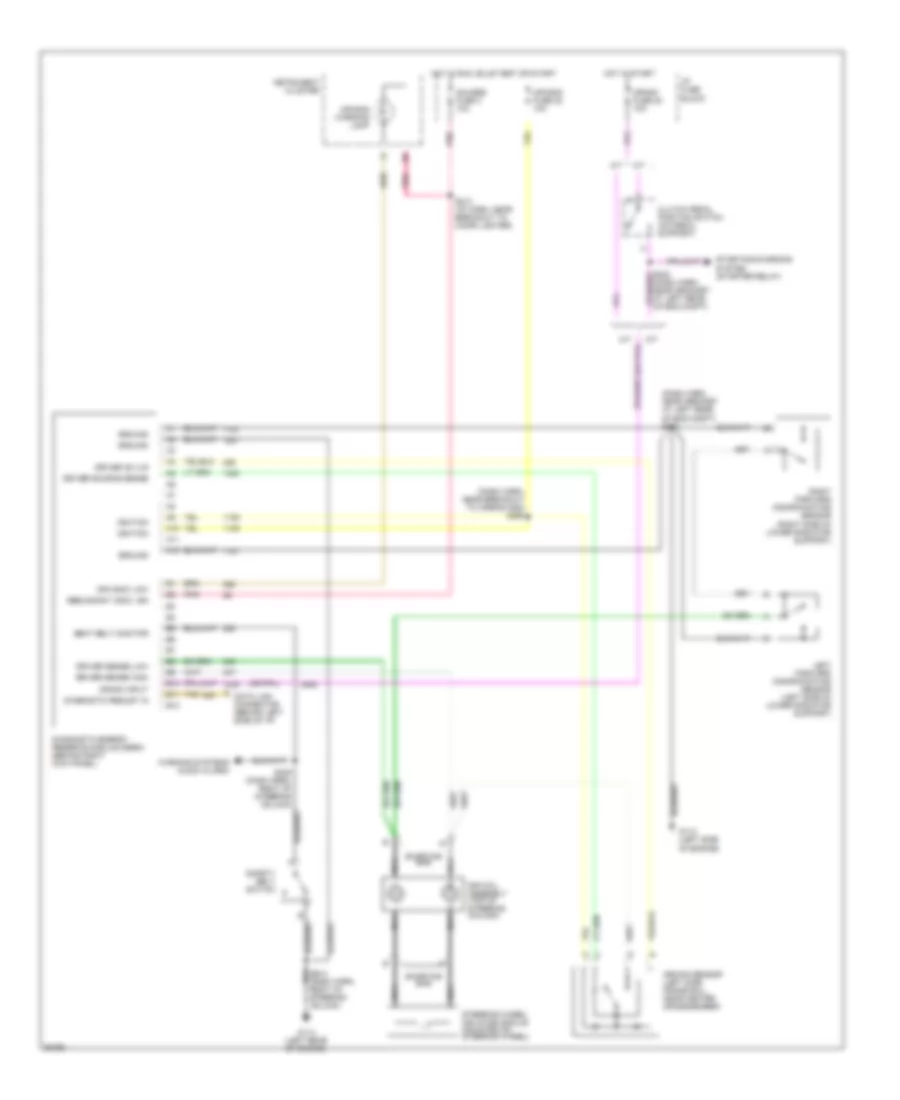
- Anti-lock brakes system
- Axle sw in
- C10
- C11
- C12
- C14
- C16
- Chassis ground
- Crank fuse 20 20a
- Cruise control system
- D10
- D12
- D13
- D14
- D15
- D16
- Data link connector
- Data link connector (partial) (lower left side of dash)
- Electronic shift transfer case
- Encoder channel a
- Encoder channel b
- Encoder channel c
- Encoder channel d
- Encoder channel-a
- Encoder channel-b
- Encoder channel-c
- Encoder channel-d
- Encoder ground
- Encoder signal ground
- Front axle switch (on front axle)
- Fuel level buffer, daytime running lamps relay, instrument cluster & rear window defogger switch
- G117 (rear of right cylinder head)
- Gauges fuse 4 10a
- Gnd
- Head- lamp switch
- Hot at all times
- Hot in run or start
- Hot in start
- I/p fuse block (left end of dash)
- Motor control a
- Motor control b
- Motor ground
- Park/neutral position & backup lamp switch
- Pk lps fuse 3 20a
- Pnk
- Pnp switch in (a/t)
- Pnp switch in (m/t)
- Power ground
- Radio
- Red
- S112
- S212 (i/p harn, approx 7 cm from radio breakout)
- S213
- S241
- S242
- S246
- S253
- Starting/ charging system (w/ m/t)
- Tcc brake & cruise control switch
- Transfer case select switch
- Transfer case shift control module (behind center of dash)
- Transmission range switch (left side of transmission) (a/t only)
- Turn b/u fuse 16 15a
- Turn signal lamp flasher
- Under- hood lamp
- Vehicle control module (right side of engine compt)
- Vehicle spd out
- Vehicle speed in
- Vss in
4.3L
4.3L (VIN W), Transmission Wiring Diagram, 4L60-E for GMC Sonoma 1997
List of elements for 4.3L (VIN W), Transmission Wiring Diagram, 4L60-E for GMC Sonoma 1997:
- (behind left side of dash)
- (eng harn, 19 cm from inj harn breakout) s115
- (twisted wire pair)
- 1-2 shift sol
- 1-2 shift sol ctrl
- 2-3 shift sol
- 2-3 shift sol ctrl
- 3-2 shift sol
- 3-2 sol ctrl
- 5v reference
- All times
- And start
- Anti-lock brakes system
- Automatic transmission (4l60-e)
- Battery feed
- Brake fuse 12 10a
- Brake pressure modulator valve, cruise control module & cruise control switch
- Brake signal
- Cruise control system
- Data link connector (partial) (below left side of dash)
- Ecm batt
- Ecm ign fuse 10 20a
- Ect signal
- Electronic ignition control module, crankshaft position sensor, ignition coil & fuel injectors)
- Engine controls system
- Engine coolant temperature sensor (thermostat housing)
- Fuel pump relay
- Fuel pump switch/ engine oil pressure gauge sensor
- Fuse 9 20a
- G114 (rear of left cylinder head)
- G117 (rear of right cylinder head)
- Gauges fuse 4 10a
- Hot at
- Hot in
- Hot in run
- Hot in run, bulb
- I/p fuse block
- Ignition feed
- Instrument cluster
- Malfunction indicator lamp
- Mil ctrl
- Park pawl actuator (w/ a/t) & instrument cluster
- Park pawl actuator (w/ floor shift) or instrument cluster (w/ column shift)
- Pickup
- Pnk
- Press ctrl so hi
- Press ctrl sol lo
- Pressure control solenoid
- Range signal-a
- Range signal-b
- Range signal-c
- Red
- Rev
- Run
- Run feed
- S100 (eng harn 30 cm from vcm breakout)
- S106
- S108
- S140
- S220
- S227 (dash harn, approx 8 cm from data link conn breakout)
- S238 (dash harn, approx 11 cm from tcc brake & cruise control rel sw breakout)
- S239
- S266
- Sensor ground
- Serial data
- Shield
- System gnd
- Tan
- Tcc brake & cruise control release switch (on brake pedal bracket)
- Tcc pwm sol
- Tcc pwm sol ctrl
- Tcc sol
- Tcc sol ctrl
- Test or start
- Tft signal
- Throttle position sensor
- Tp signal
- Trans fuse 24 10a
- Transmission fluid temperature sensor
- Transmission range pressure switch assembly
- Utility
- Vehicle control module (right side of engine compt)
- Vehicle speed sensor (on transmission-2wd) (on transfer case-4wd)
- Vss hi
- Vss lo
4.3L (VIN X), Transmission Wiring Diagram, 4L60-E for GMC Sonoma 1997
List of elements for 4.3L (VIN X), Transmission Wiring Diagram, 4L60-E for GMC Sonoma 1997:
- (behind left side of dash)
- (eng harn, 19 cm from inj harn breakout) s115
- (twisted wire pair)
- 1-2 shift sol
- 1-2 shift sol ctrl
- 2-3 shift sol
- 2-3 shift sol ctrl
- 3-2 shift sol
- 3-2 sol ctrl
- 5v reference
- All times
- And start
- Anti-lock brakes system
- Automatic transmission (4l60-e)
- Battery feed
- Brake fuse 12 10a
- Brake pressure modulator valve, cruise control module & cruise control switch
- Brake signal
- Cruise control system
- Data link connector (partial) (below left side of dash)
- Ecm batt
- Ecm ign fuse 10 20a
- Ect signal
- Electronic ignition control module, crankshaft position sensor, ignition coil & fuel injectors)
- Engine controls system
- Engine coolant temperature sensor (thermostat housing)
- Fuel pump relay
- Fuel pump switch/ engine oil pressure gauge sensor
- Fuse 9 20a
- G114 (rear of left cylinder head)
- G117 (rear of right cylinder head)
- Gauges fuse 4 10a
- Hot at
- Hot in
- Hot in run
- Hot in run, bulb
- I/p fuse block
- Ignition feed
- Instrument cluster
- Malfunction indicator lamp
- Mil ctrl
- Park pawl actuator (w/ a/t) & instrument cluster
- Park pawl actuator (w/ floor shift) or instrument cluster (w/ column shift)
- Pickup
- Pnk
- Press ctrl so hi
- Press ctrl sol lo
- Pressure control solenoid
- Range signal-a
- Range signal-b
- Range signal-c
- Red
- Rev
- Run
- Run feed
- S100 (eng harn 30 cm from vcm breakout)
- S106
- S108
- S140
- S220
- S227 (dash harn, approx 8 cm from data link conn breakout)
- S238 (dash harn, approx 11 cm from tcc brake & cruise control rel sw breakout)
- S239
- S266
- Sensor ground
- Serial data
- Shield
- System gnd
- Tan
- Tcc brake & cruise control release switch (on brake pedal bracket)
- Tcc pwm sol
- Tcc pwm sol ctrl
- Tcc sol
- Tcc sol ctrl
- Test or start
- Tft signal
- Throttle position sensor
- Tp signal
- Trans fuse 24 10a
- Transmission fluid temperature sensor
- Transmission range pressure switch assembly
- Utility
- Vehicle control module (right side of engine compt)
- Vehicle speed sensor (on transmission-2wd) (on transfer case-4wd)
- Vss hi
- Vss lo
Electronic Transfer Case Wiring Diagram for GMC Sonoma 1997
List of elements for Electronic Transfer Case Wiring Diagram for GMC Sonoma 1997:
- (a/t only)
- (a/t) 4wd lo selected
- (a/t) pnp switch in (p)
- (dash harn, 20 cm from breakout of 23-pin conn behind right side of dash) s259
- (m/t only)
- (w/ m/t only)
- 12v battery
- 12v ignition
- 2 hi request
- 2 hi status lamp
- 2wd hi indicator
- 2wd hi switch
- 4 hi request
- 4 hi status lamp
- 4 lo request
- 4 lo status lamp
- 4wd fuse 19 20 a
- 4wd hi indicator
- 4wd hi switch
- 4wd lo in
- 4wd lo indicator
- 4wd lo switch
- A/c compressor relay & inflatable restraint diagnostic energy reserve module
- Anti-lock brakes system
- Axle sw in
- C10
- C11
- C12
- C14
- C16
- Chassis ground
- Crank fuse 20 20a
- Cruise control system
- D10
- D12
- D13
- D14
- D15
- D16
- Data link connector
- Data link connector (partial) (lower left side of dash)
- Electronic shift transfer case
- Encoder channel a
- Encoder channel b
- Encoder channel c
- Encoder channel d
- Encoder channel-a
- Encoder channel-b
- Encoder channel-c
- Encoder channel-d
- Encoder ground
- Encoder signal ground
- Front axle switch (on front axle)
- Fuel level buffer, daytime running lamps relay, instrument cluster & rear window defogger switch
- G117 (rear of right cylinder head)
- Gauges fuse 4 10a
- Gnd
- Head- lamp switch
- Hot at all times
- Hot in run or start
- Hot in start
- I/p fuse block (left end of dash)
- Motor control a
- Motor control b
- Motor ground
- Park/neutral position & backup lamp switch
- Pk lps fuse 3 20a
- Pnk
- Pnp switch in (a/t)
- Pnp switch in (m/t)
- Power ground
- Radio
- Red
- S112
- S212 (i/p harn, approx 7 cm from radio breakout)
- S213
- S241
- S242
- S246
- S253
- Starting/ charging system (w/ m/t)
- Tcc brake & cruise control switch
- Transfer case select switch
- Transfer case shift control module (behind center of dash)
- Transmission range switch (left side of transmission) (a/t only)
- Turn b/u fuse 16 15a
- Turn signal lamp flasher
- Under- hood lamp
- Vehicle control module (right side of engine compt)
- Vehicle spd out
- Vehicle speed in
- Vss in
WARNING SYSTEMS
Warning System Wiring Diagrams for GMC Sonoma 1997
List of elements for Warning System Wiring Diagrams for GMC Sonoma 1997:
- 2.2l eng
- 4.3l eng
- Fasten belts output
- G112 (left side of engine, below exhaust manifold)
- G114 (left rear of engine)
- G117 (right rear of engine, on head)
- G123 (right rear of engine compt)
- Gauges fuse 4 10a
- Ground
- Hot at all times
- Hot in park or head
- Hot in run and start
- I/p fuse block
- Ignition key alarm switch
- Ignition on input
- Illum fuse 21 10a
- Instrument cluster
- Key-in warning
- Left front side door jamb switch
- Lights on input
- Nca
- Pnk
- Power input
- S109
- S112
- S205
- S209
- S210
- S213
- S222
- S244
- S245 (dash harn, 28 cm right of steering column breakout)
- Safety belt lamp
- Safety belt retractor switch
- Seat belt input
- Seat belts, ignition key, and lamps alarm (power distribution center)
- Stop haz fuse 1 20a
- Tan
WIPER/WASHER
Front Wiper/Washer Wiring Diagram for GMC Sonoma 1997
List of elements for Front Wiper/Washer Wiring Diagram for GMC Sonoma 1997:
- (left radiator support)
- (left rear of engine)
- C 1995 vftc
- G108
- G114
- Hot in acc or run
- I/p fuse block
- Low
- Mist
- Off
- Pnk
- Pulse
- S120
- S230
- Solid state
- Washer switch
- Windshield washer pump (left front of engine compt, in washer reservoir)
- Windshield wiper motor & module (center rear of engine compt)
- Wiper fuse 17 25a
- Wiper switch
- Wiper/ washer switch

 Čeština
 Dansk
Dansk Deutsch
 Ελληνικά
 English
 English
 Español
 Suomi
Suomi Français
 Français
 עברית
עברית Magyar
 Italiano
 日本語
日本語 한국어
한국어 Nederlands
 Polski
 Português
 Português
 Română
 Русский
 Slovenčina
 Slovenščina
 Svenska
 Türkçe
 中文 (中国)