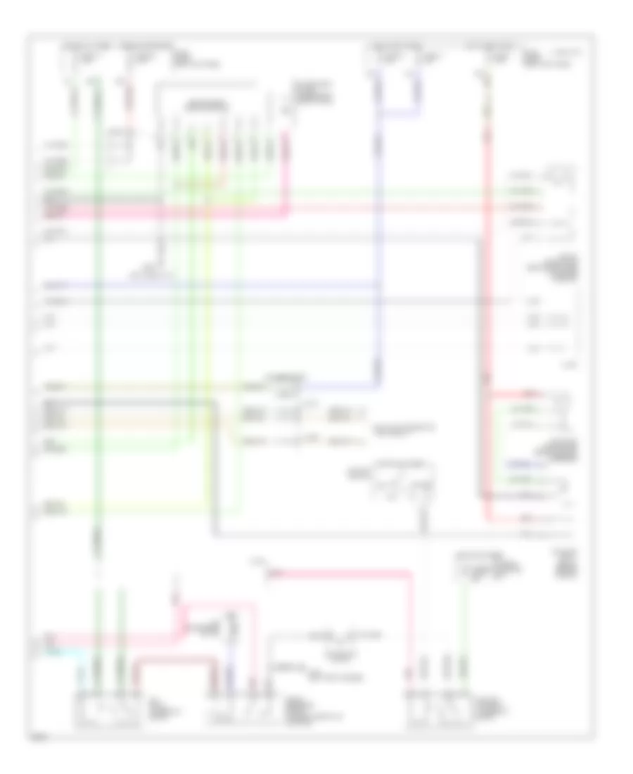
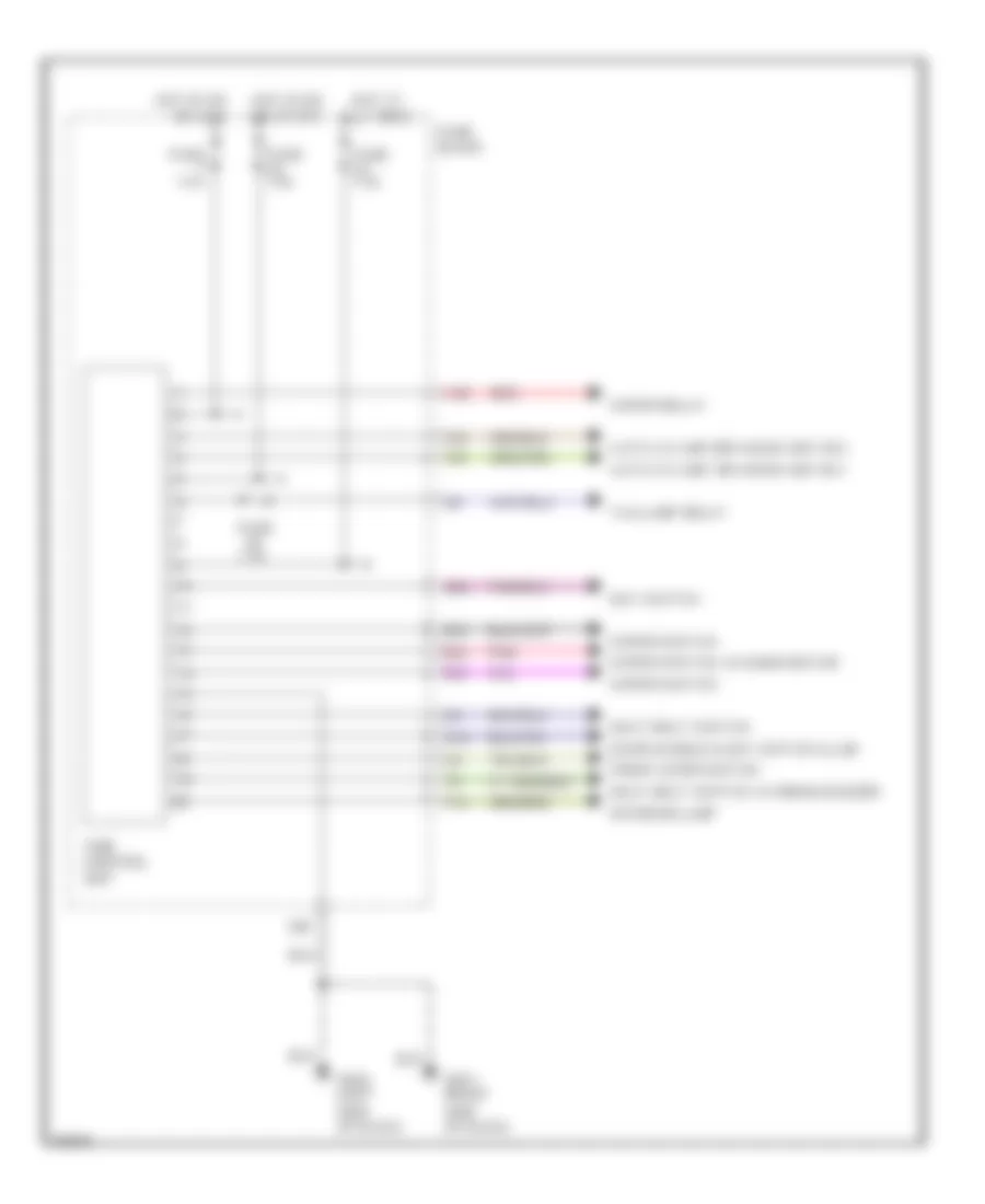
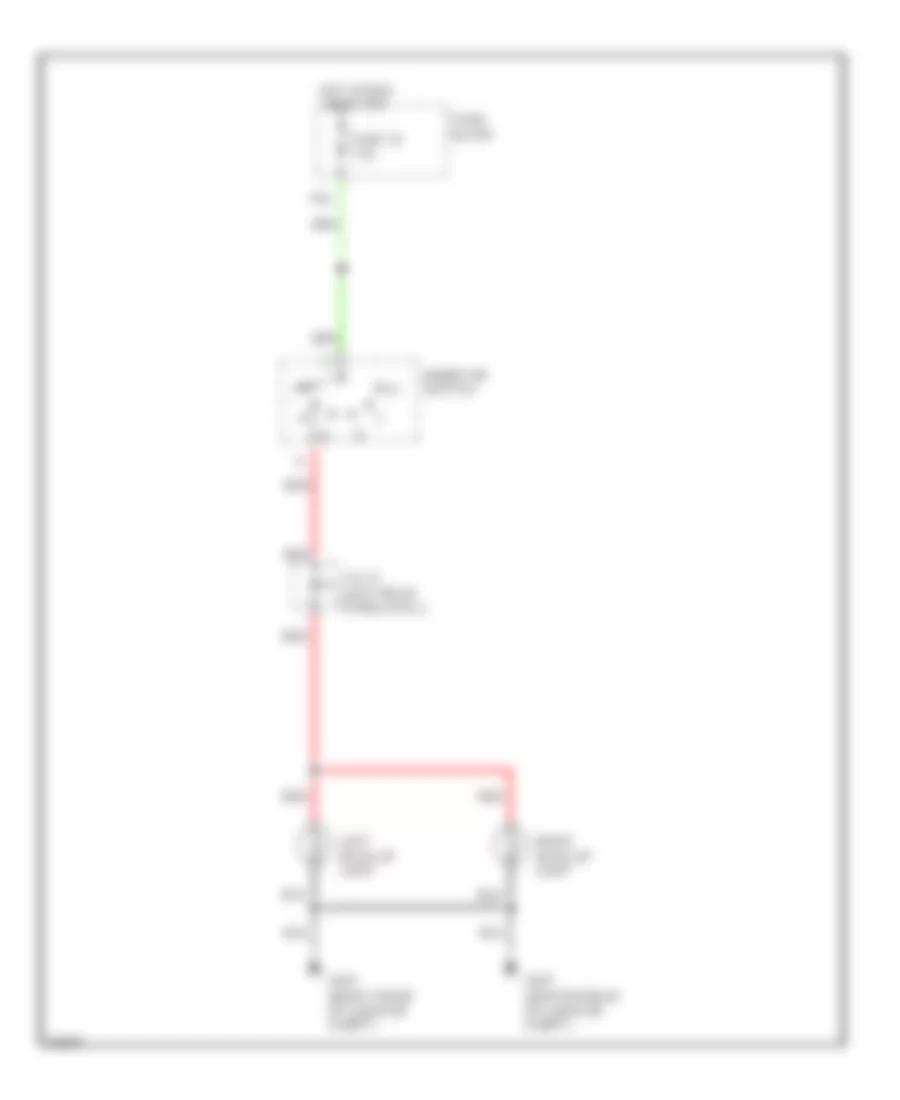
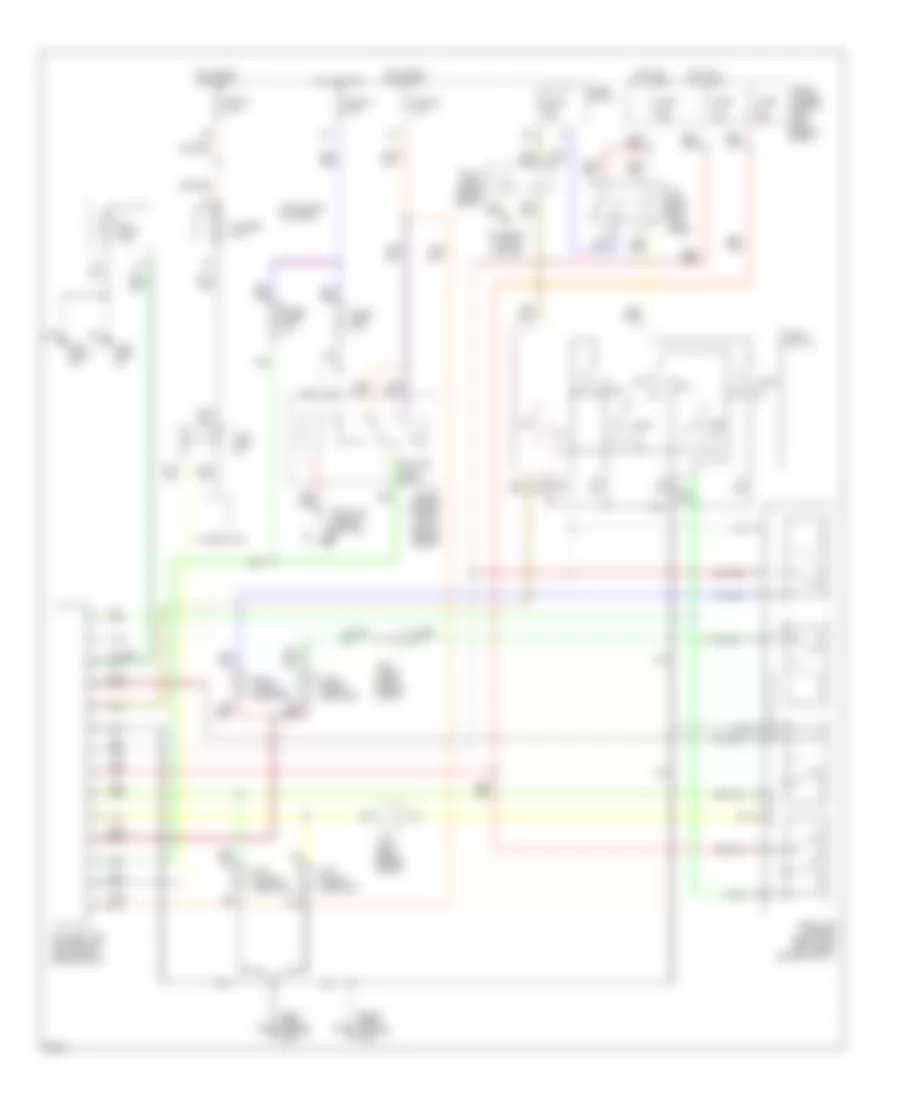
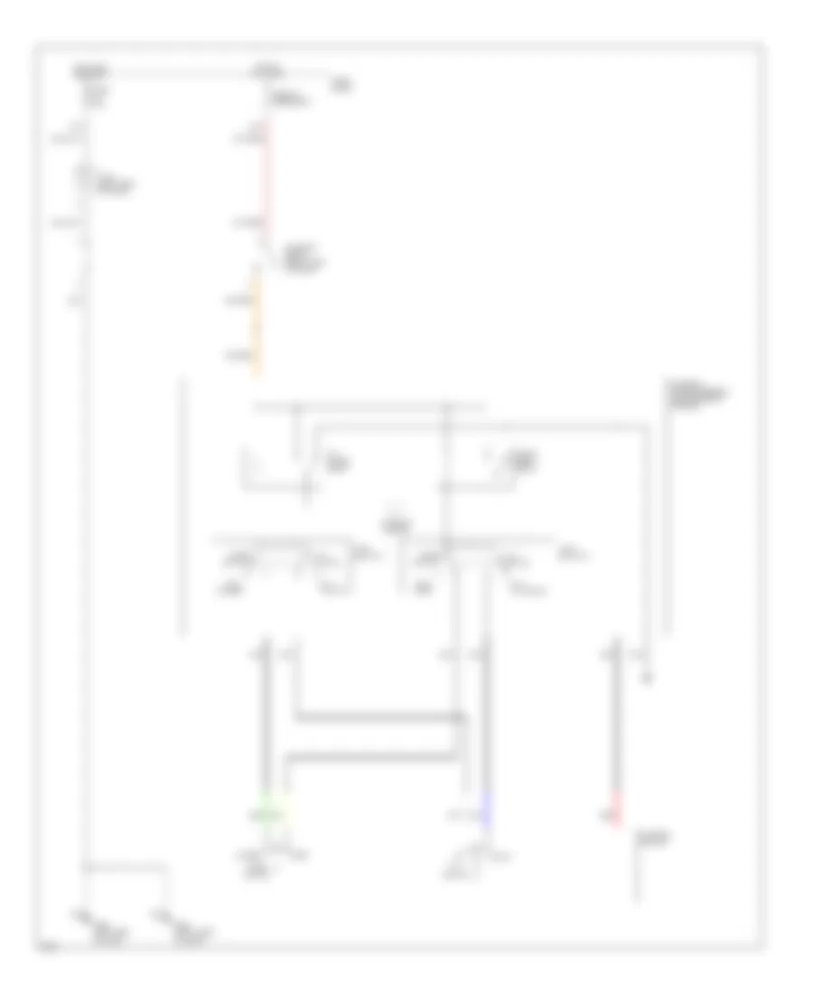
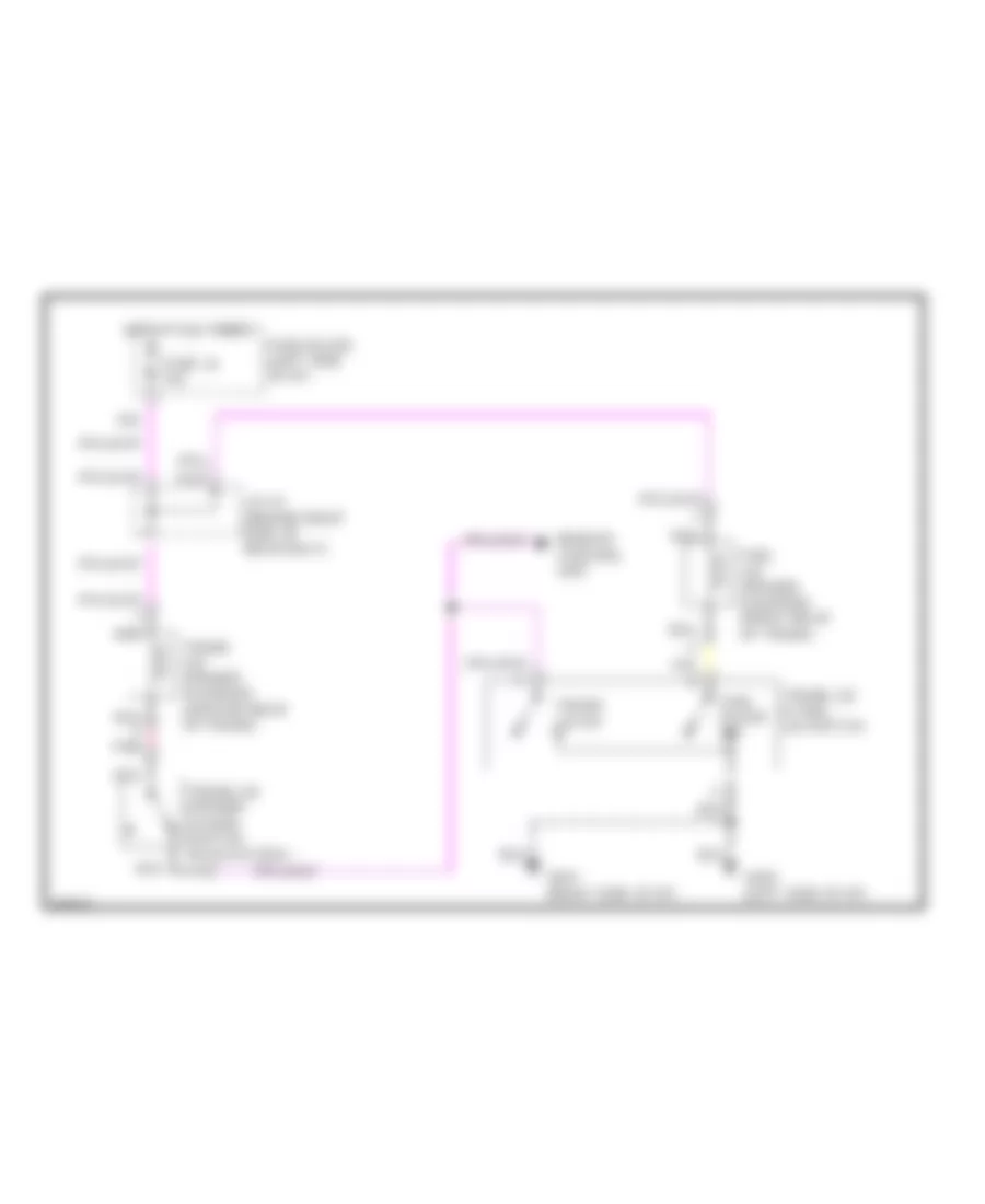
AIR CONDITIONING
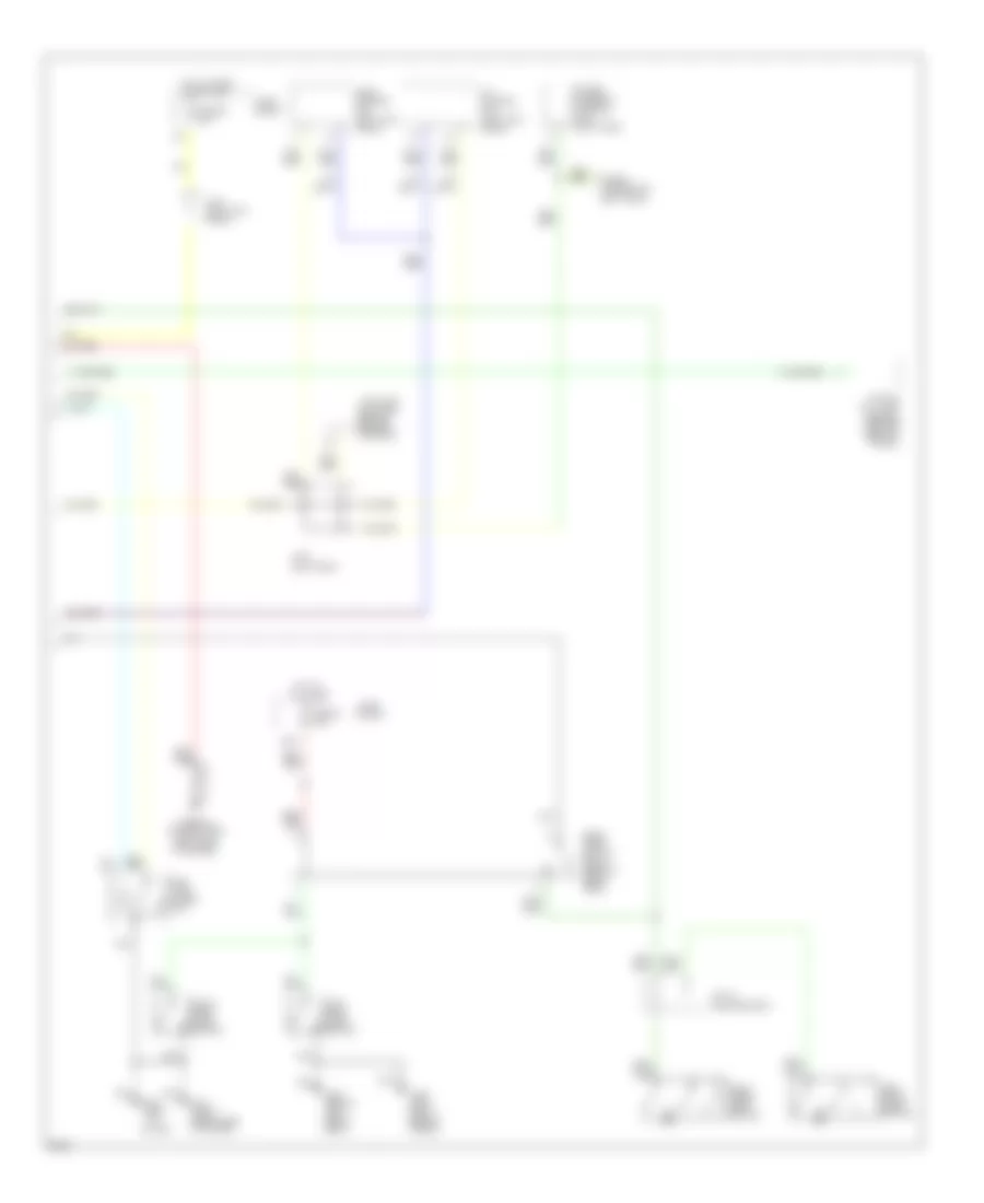
Air Conditioning Wiring Diagrams (1 of 2) for Infiniti J30 1997
 https://portal-diagnostov.com/license.html
Automotive Electricians Portal FZCO
Automotive Electricians Portal FZCO
https://portal-diagnostov.com/license.html
https://portal-diagnostov.com/license.html
Automotive Electricians Portal FZCO
Automotive Electricians Portal FZCO
List of elements for Air Conditioning Wiring Diagrams (1 of 2) for Infiniti J30 1997:
- (behind right kick panel)
- (center of i/p)
- (front left fender)
- (front of engine)
- 1994 vftc c
- Ambient sensor (front of engine compartment)
- Auto amp (behind center of dash, in evaporator case)
- B/l
- Blower high relay (behind glove box)
- Def
- Eccs control unit
- F/d
- Fan control amp (right side of i/p)
- Foot
- G100
- Heater & a/c selector switch
- In car sensor (on center console, left of radio)
- Instrument cluster system (speedometer)
- Intake sensor (inside evaporator case)
- Interior lights system
- J/c 9
- Mode door motor
- Pnk
- Push control unit
- Red
- Sunload sensor (right side of dash)
- Thermal transmitter
- Time control unit (in fuse block)
- Vent
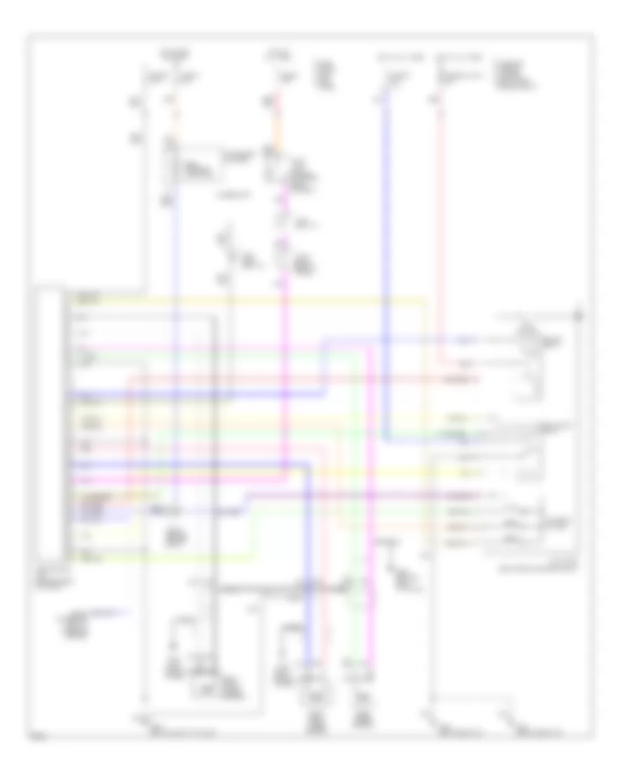
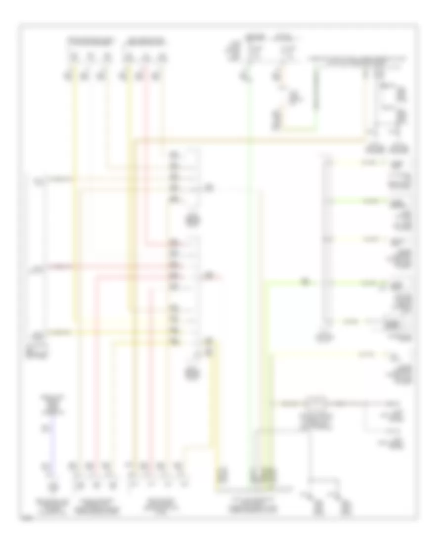
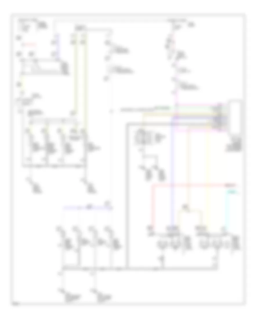
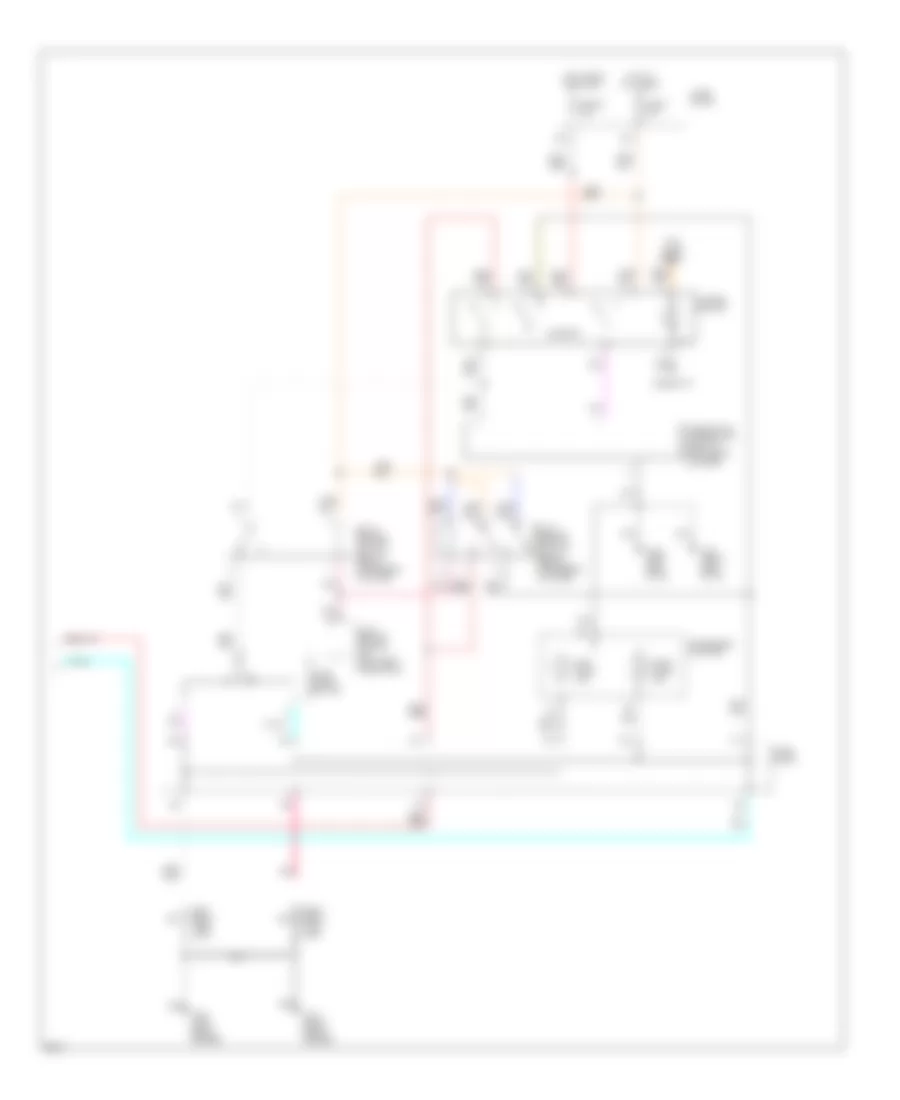
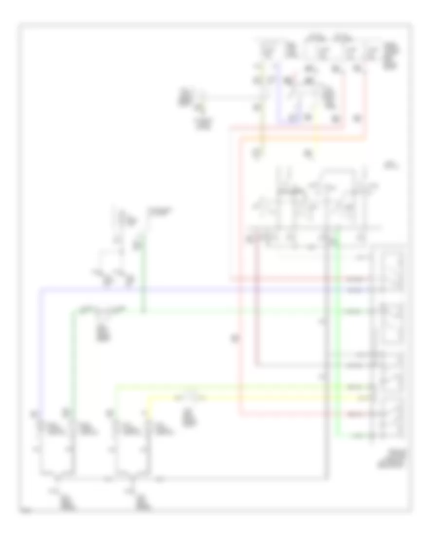
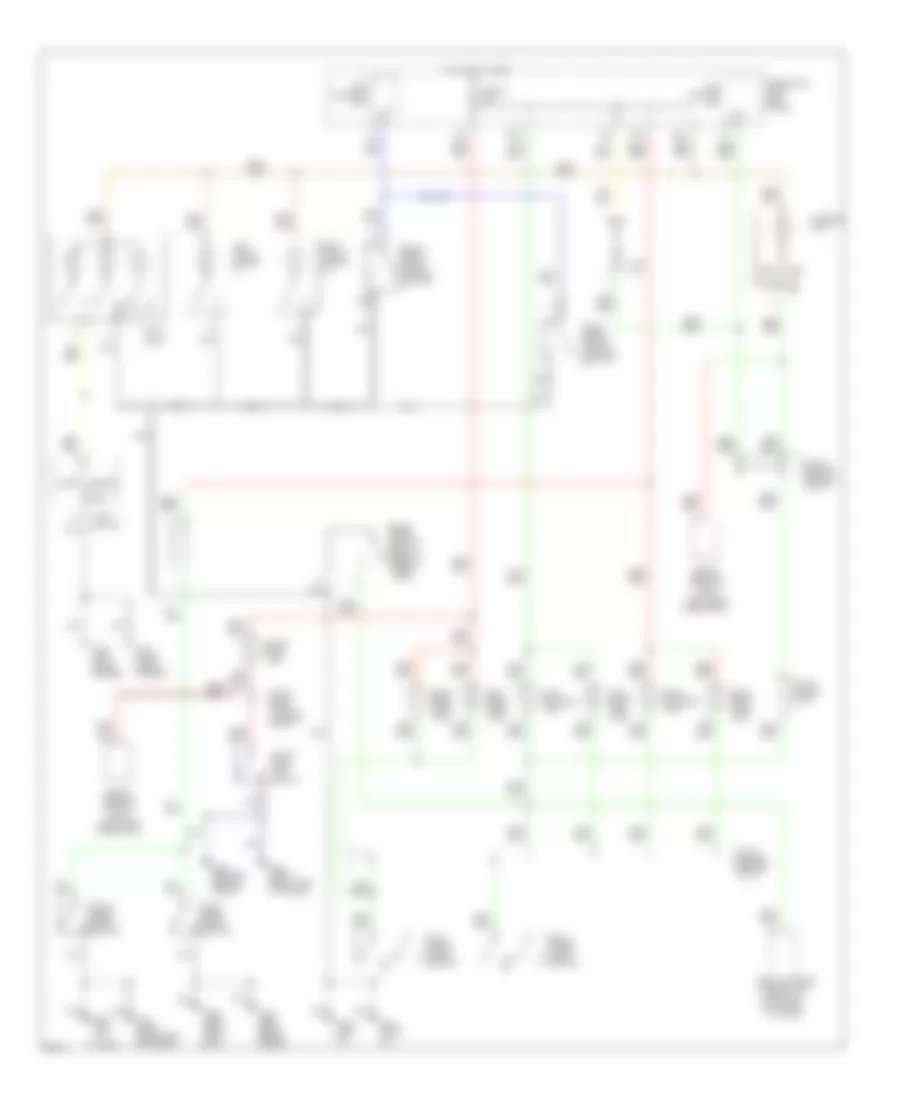
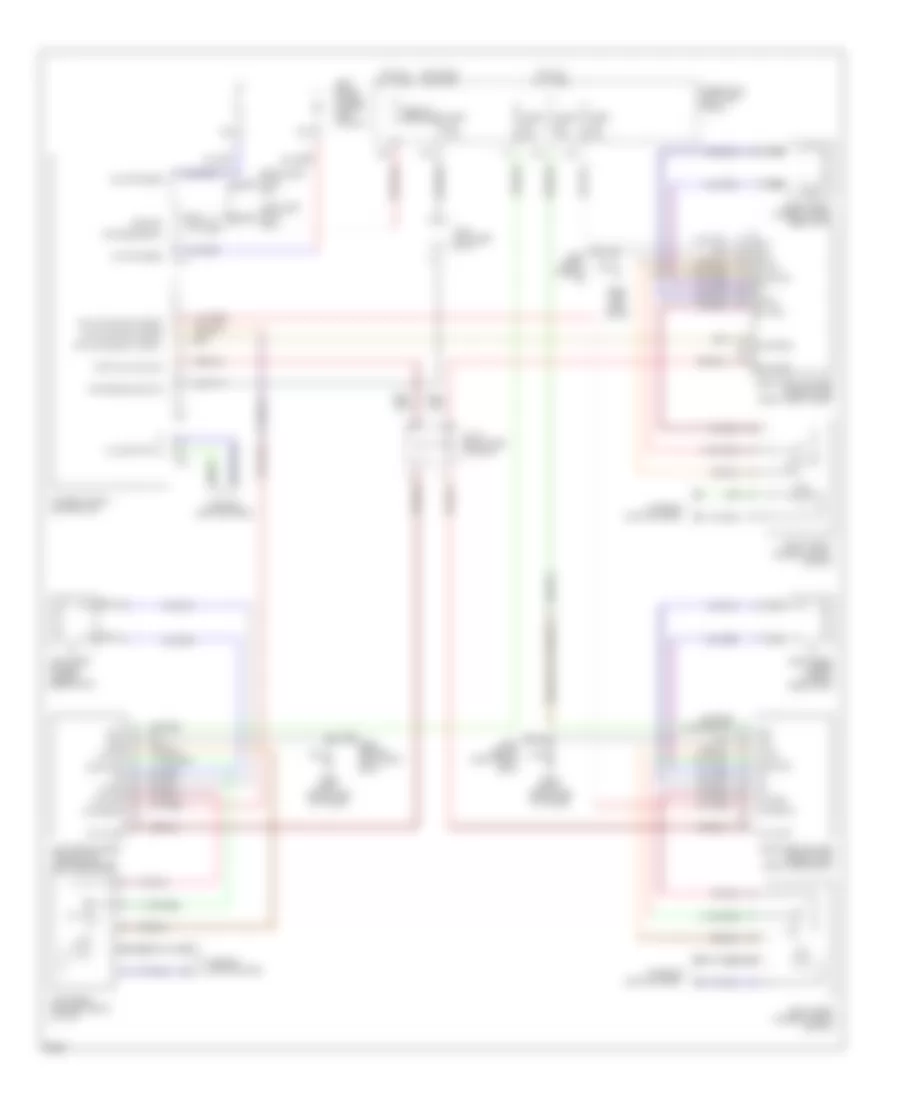
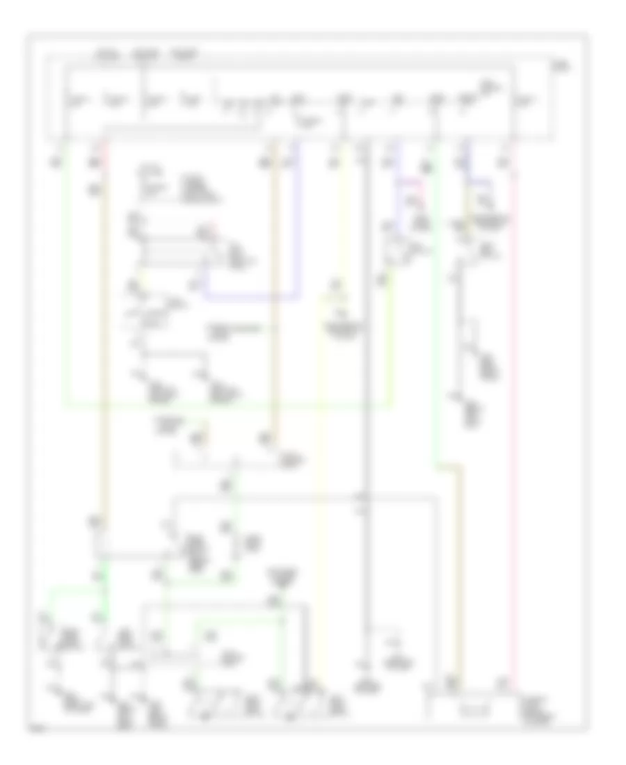
Air Conditioning Wiring Diagrams (2 of 2) for Infiniti J30 1997
List of elements for Air Conditioning Wiring Diagrams (2 of 2) for Infiniti J30 1997:
- (below center cosole)
- (left side of i/p)
- 15e
- 1994 vftc c
- 29a
- 44a
- 48a
- 69a
- A/c compressor clutch
- A/c relay (fuse/relay block)
- Acc
- Air mix door motor (behind right side of center console)
- Blower motor
- Cooling fan motor
- Cooling fan relay (fuse/relay block)
- Data link connector for consult
- Fuse 10 15a
- Fuse 11 15a
- Fuse 13 7.5a
- Fuse 22 7.5a
- Fuse 7 7.5a
- Fuse block (left kick panel)
- Fusible link b 25a
- Fusible link/fuse box
- G100 (left front fender)
- G202
- Hot at all times
- Hot at all times
- Hot in accy or on
- Hot in on or start
- Ignition switch
- Intake door motor (under right side of dash)
- J/c #11
- J/c #3
- J/c #7
- J/c #9
- Max cold door motor (behind center console)
- Max cold relay
- Off
- Pnk
- Recirc/fresh position switch
- Red
- Start
- Triple pressure switch (under evaporative canister)
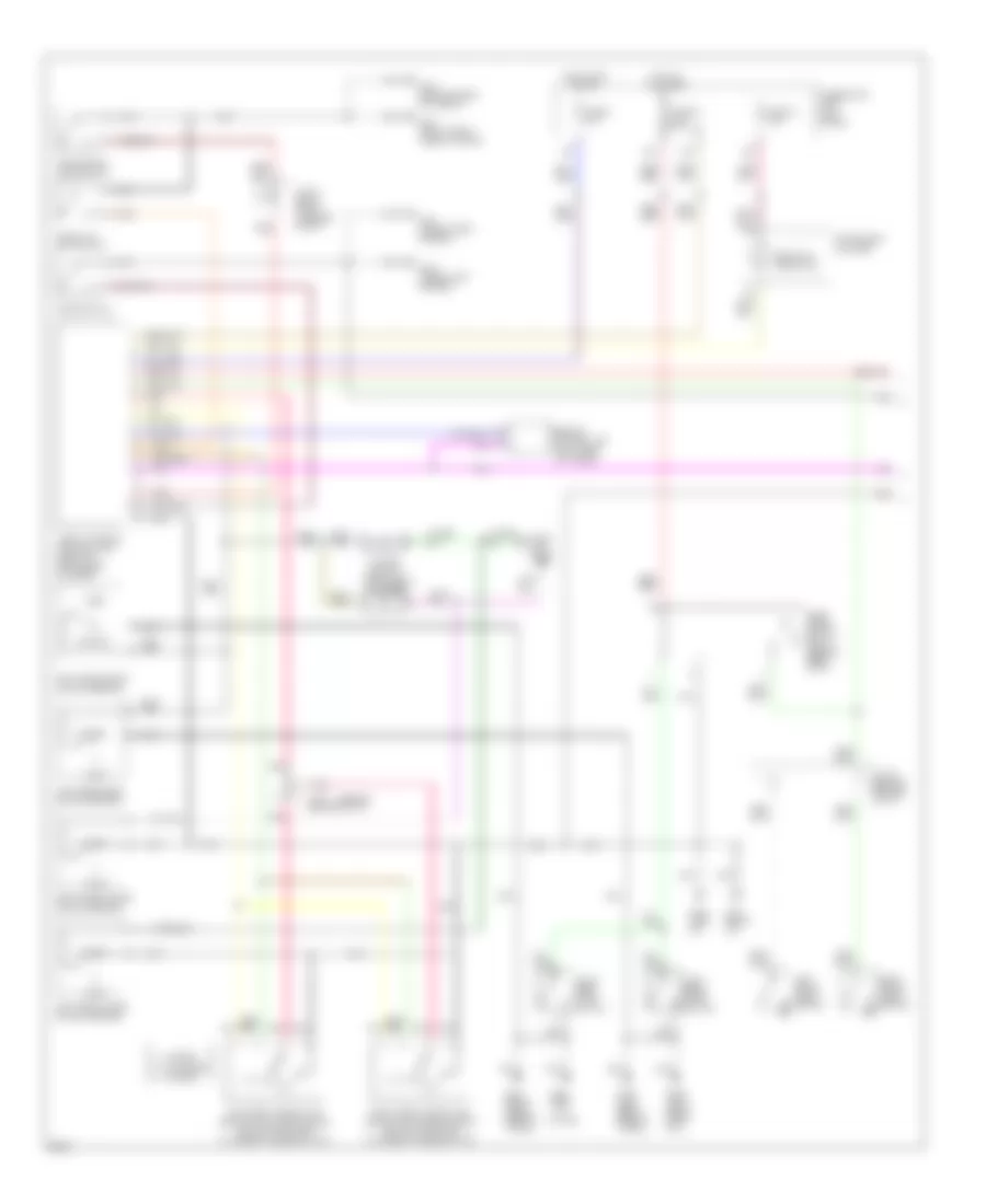
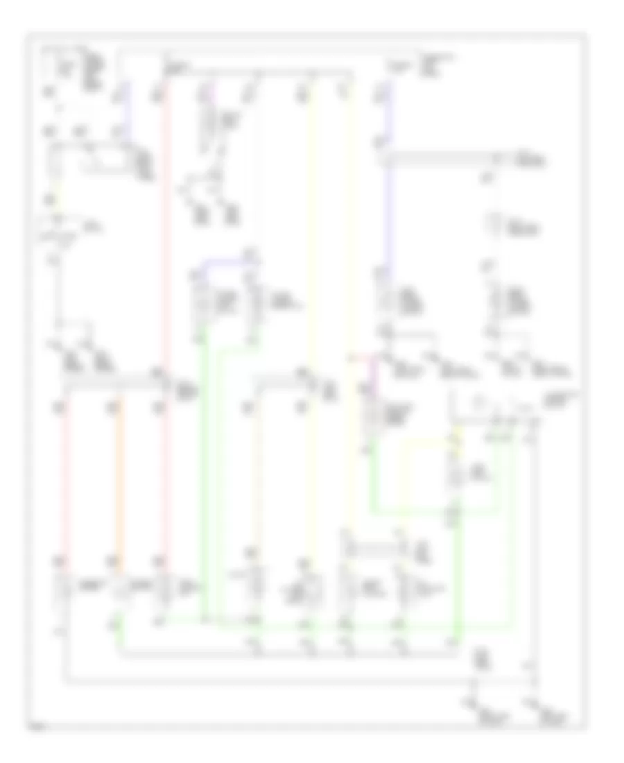
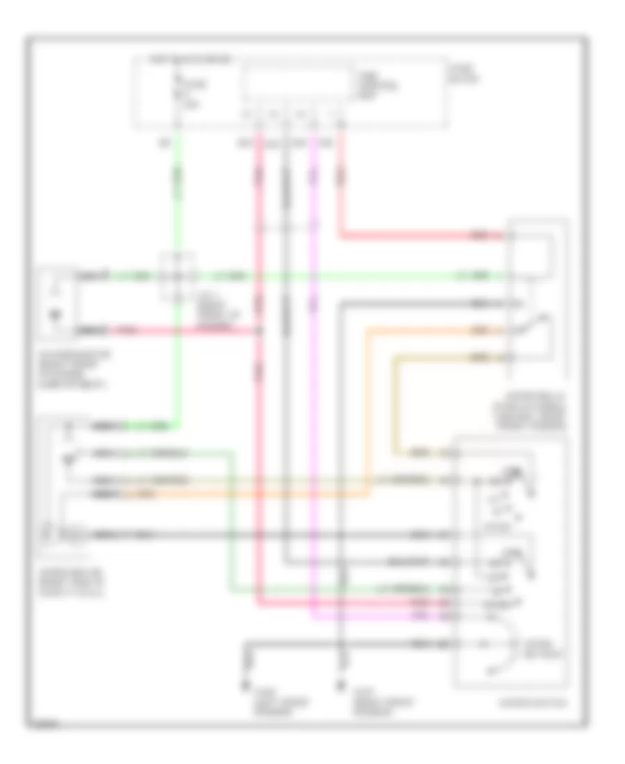
ANTI-LOCK BRAKES
Anti-lock Brake Wiring Diagrams for Infiniti J30 1997
List of elements for Anti-lock Brake Wiring Diagrams for Infiniti J30 1997:
- (right rear of engine compt)
- (right shock tower)
- Abs control
- Abs warning indicator
- Actuator
- Actuator relay
- All times
- Alternator
- Fuse 20 7.5a
- Fuse 31 7.5a
- Fuse 4 15a
- Fuse 57 20a
- Fuse and fusible link box (right side engine compt)
- Fuse block (left kick panel)
- Fusible link c 30a
- G102 (left shock tower)
- G103
- G201 (right side of i/p)
- G202 (left side of i/p)
- G904 (bottom left "c" pillar)
- G905 (bottom right "c" pillar)
- Hot at
- Hot at all times
- Hot in run or start
- Instrument cluster
- J/c-10 (behind center of i/p)
- J/c-13 (right rear of trunk)
- J/c-6 (left i/p)
- J/c-7 (1995) (left i/p)
- Left front wheel sensor
- Motor
- Motor relay
- Nca
- Pnk
- Rear wheel sensor
- Red
- Right front wheel sensor
- Solenoid valves
- Stop lamp switch (on brake pedal support)
- Unit (center rear of trunk)
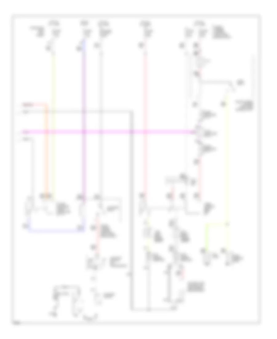
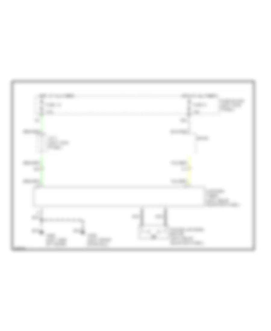
ANTI-THEFT
Anti-theft Wiring Diagram (1 of 2) for Infiniti J30 1997
List of elements for Anti-theft Wiring Diagram (1 of 2) for Infiniti J30 1997:
- "c"
- (behind
- (center rear
- (front left
- (front right
- (left rear of trunk)
- (right front
- (right of instrument
- (right of instrument cluster)
- 10g
- 12g
- Cluster)
- Control unit
- Diodes
- Door lock timer
- Fender)
- Fuse 13 7.5a
- Fuse 23 7.5a
- Fuse 8 10a
- Fuse block (left kick panel)
- G100
- G101
- G201 (right i/p)
- G202 (left i/p)
- G309 (left front door sill)
- G401
- G401 (right front side of trunk)
- G404 (left rear side of trunk)
- G407
- G904 (left
- Hood switch
- Hot at all times
- Hot in acc or run
- Instrument cluster
- J/c-10 (behind center of i/p)
- J/c-13 (right front luggage compt)
- J/c-9 center of i/p)
- Left front door lock key switch, door unlock key switch & key cylinder tamper switch
- Left front door switch
- Left front door unlock sensor
- Left rear door
- Left rear door unlock sensor
- Lock
- Locked
- Of trunk)
- Pillar)
- Pnk
- Rear door switch relay
- Rear seat)
- Red
- Remote control unit
- Right front door lock key switch, door unlock key switch & key cylinder tamper switch
- Right front door switch
- Right front door unlock sensor
- Right rear door
- Right rear door unlock sensor
- Security indicator
- Side of trunk)
- Switch
- Tamper
- Theft warning
- Trunk lid key switch
- Trunk room lamp switch
- Unlock
- Unlocked
Anti-theft Wiring Diagram (2 of 2) for Infiniti J30 1997
List of elements for Anti-theft Wiring Diagram (2 of 2) for Infiniti J30 1997:
- (left kick
- 1-2
- 74a
- Battery
- Daytime light control unit (left side of engine compt)
- Diode (left side of i/p)
- Engine compt)
- Fuse & fusible link box (right side
- Fuse 10a
- Fuse 15a
- Fuse 7.5a
- Fuse block
- Fusible link a 30a
- Horn
- Horn relay
- Hot at all times
- Hot in start
- Inhibitor switch (on
- J/c-1 (right front engine compt)
- J/c-2 (left front engine compt)
- J/c-3
- J/c-7 (left i/p)
- J/c-8 (left side of i/p)
- Left hi beam headlamp
- Low
- Nca
- Panel)
- Right hi beam headlamp
- Starter motor
- Starter relay
- Theft
- Theft starter relay (left side of i/p)
- Theft warning relay (left i/p)
- Transmission)
- W/ drl
- W/o drl
- Warning
BODY COMPUTER
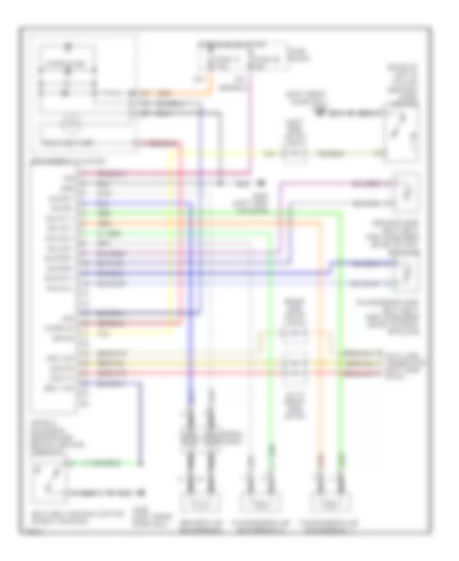
Time Control Unit Wiring Diagram for Infiniti J30 1997
List of elements for Time Control Unit Wiring Diagram for Infiniti J30 1997:
- 10a
- 11a
- 12a
- 12b
- 14e
- 28a
- 81a
- 82a
- 83a
- 84a
- Auto a/c amp (rr wdow def sw)
- Auto a/c amp, rr wdow def rly
- Door handle & key switch illum
- Front door switch
- Fuse 7.5a
- Fuse block
- G201 (right
- G202 (left
- Hot at all times
- Hot in on or acc
- Hot in on or start
- Interior lamp
- Key switch
- Pnk
- Red
- Seat belt switch
- Seat belt switch, warning buzzer
- Side of dash)
- Taillamp relay
- Time control unit
- Wiper relay
- Wiper switch
- Wiper switch, washer motor
COMPUTER DATA LINES
Computer Data Lines for Infiniti J30 1997
List of elements for Computer Data Lines for Infiniti J30 1997:
- (behind center of dash) a/c auto amplifier
- (behind left side of dash) check connector
- (left front
- (left side of dash) ascd control unit
- (right front
- (under left side of dash, under steering column) data link connector for gst
- A/c auto amplifier (behind center of dash)
- A/t control unit (behind left kick panel)
- Abs control unit (under center of rear package tray)
- Air bag diagnosis sensor unit (under console, behind parking brake lever)
- Ascd control unit (left side of dash)
- Clk (hhc)
- Combination meter
- Csc
- Csr
- Cst
- Data clk
- Data in(rx)
- Data link connector for consult (under left side of dash, under steering column)
- Data out(tx)
- Ddl clk
- Ddl rx
- Ddl tx
- Eccs control module (ecm) (behind right kick panel)
- Fender)
- Fuse 7.5a
- Fuse block (on left kick panel)
- G100
- G101
- G114 (left side of engine)
- G201 (right side of i/p)
- G202 (left side of i/p)
- Gst
- Hot at all times
- Hot in on or start
- J/c 11 (behind center of i/p)
- J/c 6 (left side of i/p)
- J/c 7 (left side of i/p)
- J/c 9 (behind center of i/p)
- L/dia wake up
- M94
- P/s sol(+)
- Power steering control unit (left side of dash)
- Power steering solenoid valve (lower left front of engine)
- Rx (hhc)
- Speed sens
- Speed sensor
- Speed sne2
- Speedo- meter
- Sss clk
- Sss rx
- Sss tx
- Tx (hhc)
- Vehicle sens
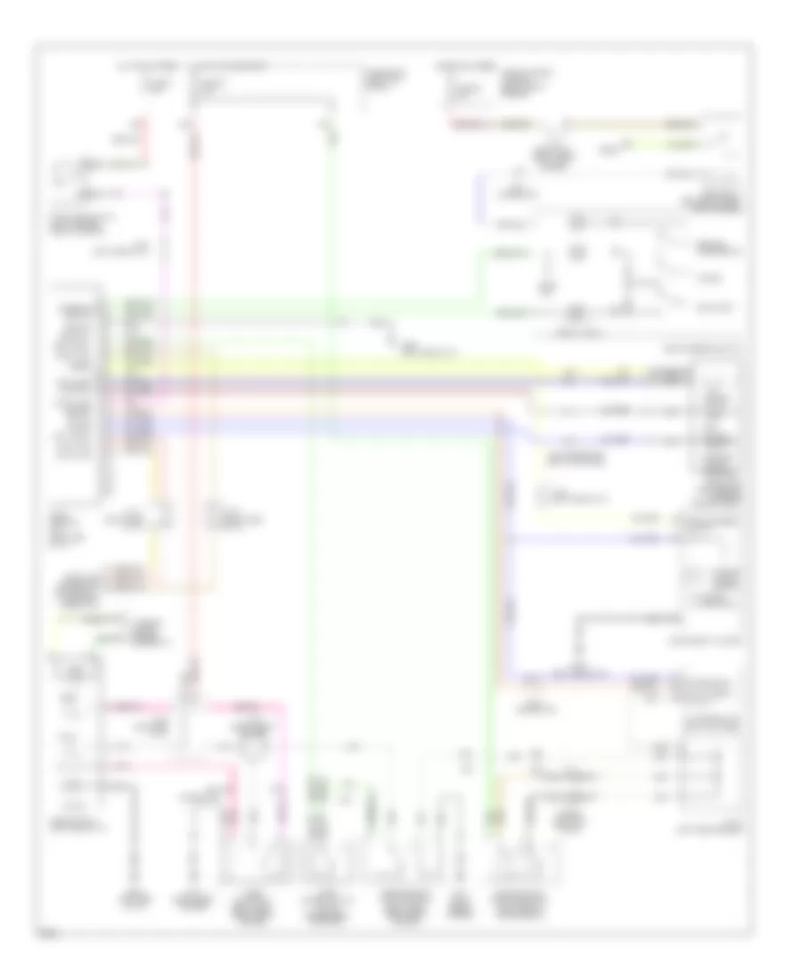
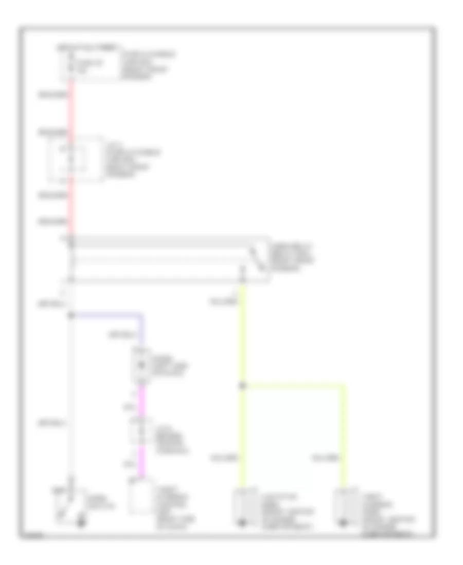
COOLING FAN
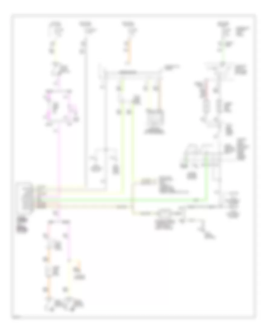
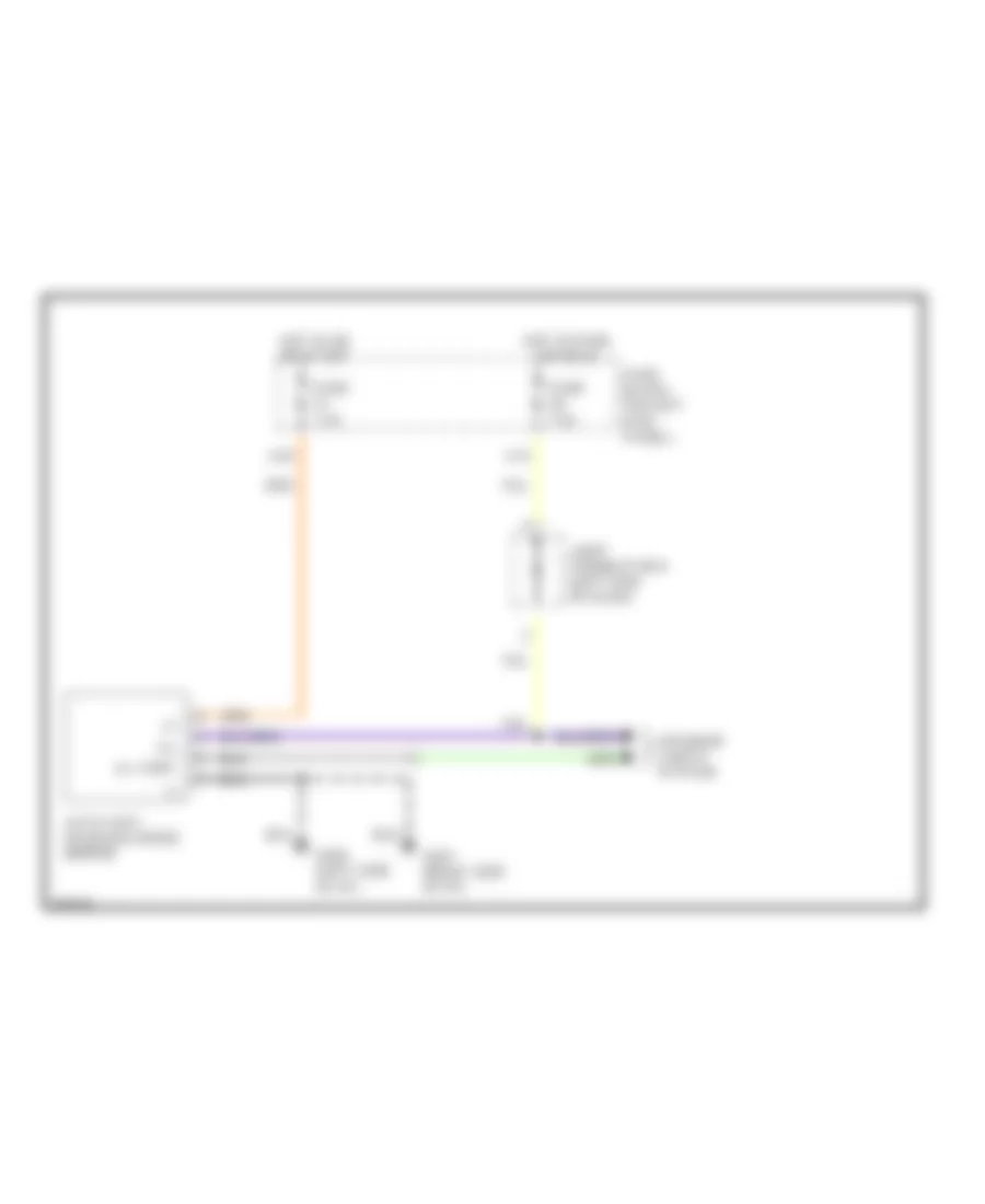
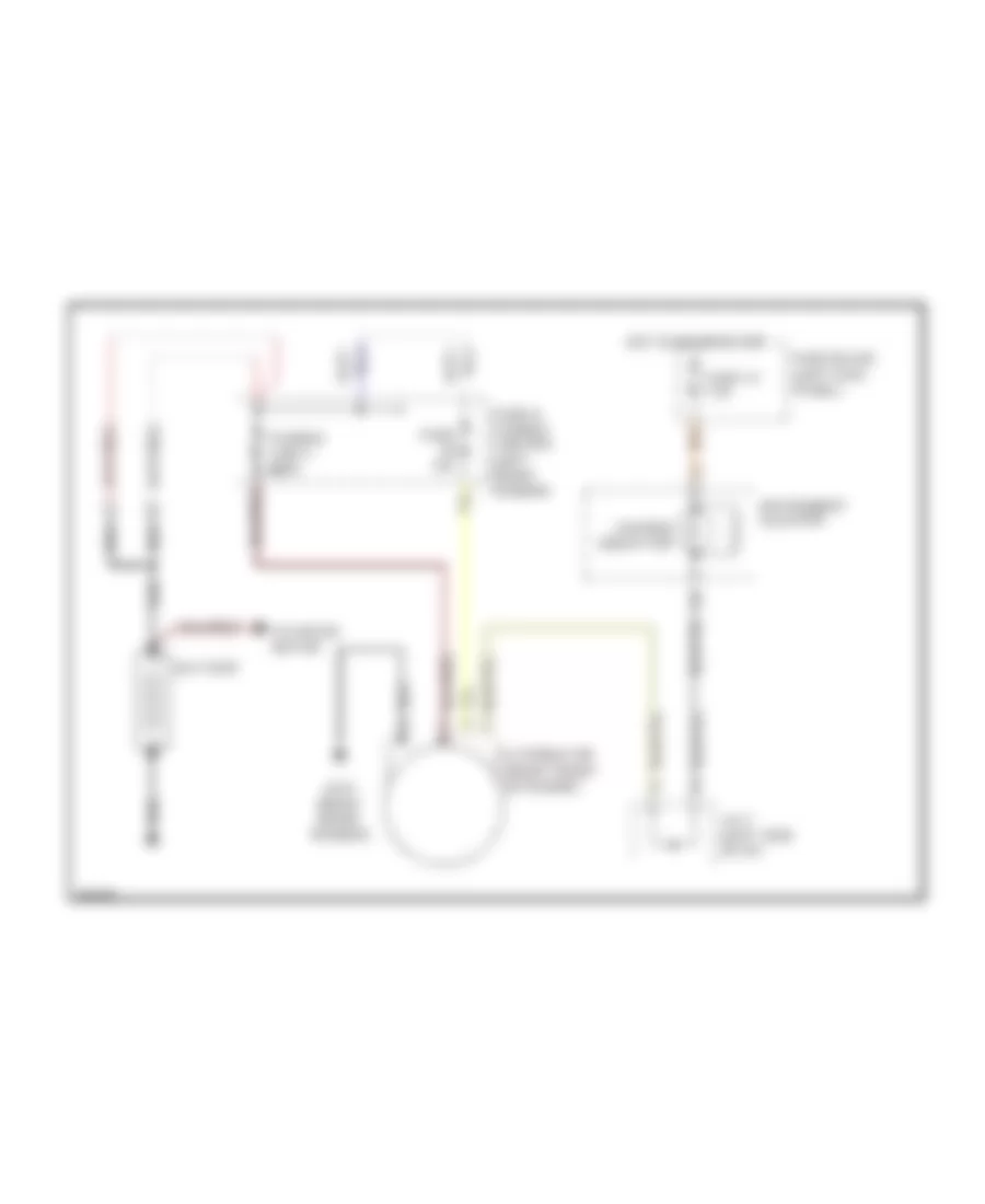
Cooling Fan Wiring Diagram for Infiniti J30 1997
List of elements for Cooling Fan Wiring Diagram for Infiniti J30 1997:
- Acc
- Cooling fan motor
- Cooling fan relay (in fuse/ relay box)
- Eccs control unit (behind right kick panel)
- Fusible link b 25a
- Fusible link/fuse box
- G100 (left front fender)
- Hot at all times
- Ignition switch
- J/c 3
- Lock
- Pnk
- Run
- Start
CRUISE CONTROL
Cruise Control Wiring Diagram for Infiniti J30 1997
List of elements for Cruise Control Wiring Diagram for Infiniti J30 1997:
- "n" or "p"
- (left rear fender)
- (left side of i/p)
- (right front fender)
- 15g
- 39a
- 55a
- A/t control unit (left kick panel)
- Act. cntrl
- Actuator control
- Air valve solenoid
- Ascd cancel switch (top of brake pedal support)
- Ascd control unit (left side of i/p)
- Ascd hold relay (relay box, right front fender)
- Ascd pump (left rear of of engine compartment)
- Ascd steering switch
- Ascd sw.
- Ascd switch (left side of i/p)
- Cancel
- Connector for consult (lower left side of i/p)
- Crs. cancl
- Cruise
- Cruise indicator
- Cruise signal
- Data link
- Diodes (left kick panel)
- Fuse & fusible link box (right front fender)
- Fuse 30 7.5a
- Fuse 4 15a
- Fuse 55 15a
- Fuse block (left kick panel)
- G101
- G101 (right front fender)
- G202
- G202 (left side of i/p)
- Ground
- Horn relay (relay box, right front fender)
- Horn sw.
- Horns
- Hot at all times
- Hot in on or start
- Illum.
- Instrument cluster
- Interior lights system
- Interior lights system (rheostat)
- J/c 11 (right side of i/p)
- J/c 12
- J/c 3 (relay box, right front fender)
- J/c 3 (right front fender)
- J/c 6 (left side of i/p)
- J/c 8 (left side of i/p)
- J/c 9 (right side of i/p)
- N15
- Nca
- Od cut signal
- On ind.
- Park/neutral position relay (relay box, right front fender)
- Park/neutral position switch (left side of transmission)
- Pnk
- Release valve solenoid
- Resume/ accelerate
- Set/coast
- Smj
- Smj connector
- Smj connector (left kick panel)
- Speed
- Spiral cable
- Steering switch
- Stop lamp switch (top of brake pedal support)
- Stop lamp switch od cut
- Vacuum motor
- Vehicle speed output
DEFOGGERS
Defogger Wiring Diagram for Infiniti J30 1997
List of elements for Defogger Wiring Diagram for Infiniti J30 1997:
- (in evaporator case)
- A/c auto amplifer
- A10
- A12
- A38
- Condenser (left "c" pillar)
- Def out
- Def sw
- Door mirror defogger relay (in fusible link box. right front fender)
- Driver's side door mirror
- Fuse & fusible link box (near battery)
- Fuse 20a
- Fuse block (left side of steering column)
- G100 (front of left front fender)
- G101 (right front fender)
- G201 (right side of i/p)
- G202 (left side of i/p)
- Hot at all times
- Hot in on or start
- J/c 3 (in fusible link box, right front fender)
- J/c 9 (right side of i/p)
- Mirror defogger
- Passenger's side door mirror
- Rear window defogger
- Rear window defogger relay (behind left kick panel)
- Rr def
- Rr def f/b
- Time control unit
ELECTRONIC POWER STEERING
Electronic Power Steering Wiring Diagram for Infiniti J30 1997
List of elements for Electronic Power Steering Wiring Diagram for Infiniti J30 1997:
- (1996-97) (1995)
- (left front
- (left rear wheel- well)
- (left side of i/p)
- (right front
- (right side of i/p)
- 1996-
- 1996-97
- 2-1
- A25 c1
- A26 c2
- A39 d11
- All times
- Combination meter
- Cruise control system
- Data link connector for consult (under left side of dash, under steering column)
- Diode (left side of i/p)
- Diodes (left kick panel)
- Fender)
- Fuse 15a
- Fuse 32 7.5a
- Fuse 7.5
- Fuse 7.5a
- Fuse block (on left kick panel)
- Fusible link, fuse & relay box (in left front inner fender panel)
- G100
- G101
- G111 (near battery)
- G15 t8
- G201
- G202
- Gnd
- Hot at
- Hot in on
- Hot in on or start
- Ign sw
- Inhibit
- Inhibitor switch (left side of trans)
- J/c 12
- J/c 6 (left side of i/p)
- J/c 7 (left side of i/p)
- Or start
- Park brake switch
- Park/ neutral position relay
- Pb sw
- Power steering solenoid valve
- Power steering steering steering steering control unit (behind (behind (behind (behind left side left side left side left side of dash)
- Ps sol
- Side of engine)
- Speedometer
- Stop lamp
- Stop lamp switch
- Stp sw
- V sens
- Vehicle speed sensor (on transmission)
- Warning systems
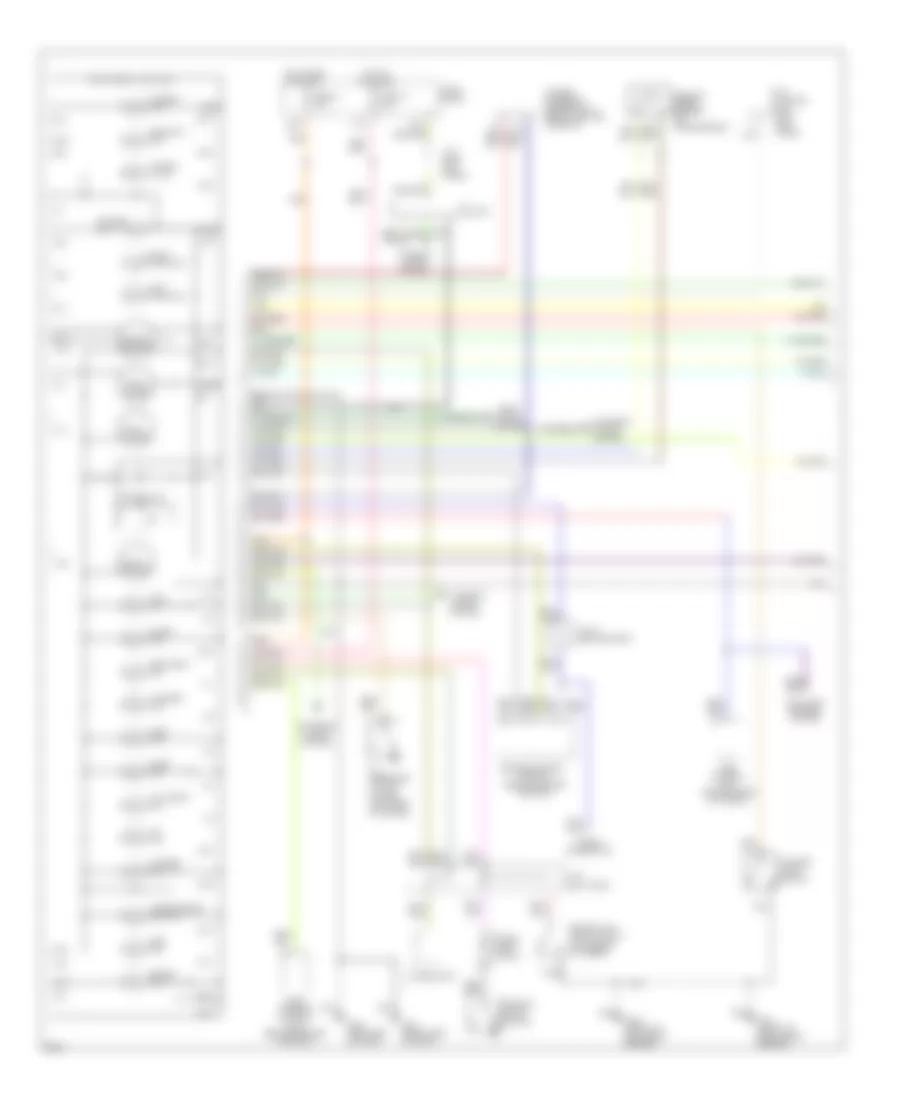
ENGINE PERFORMANCE
3.0L
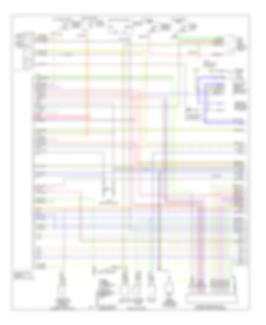
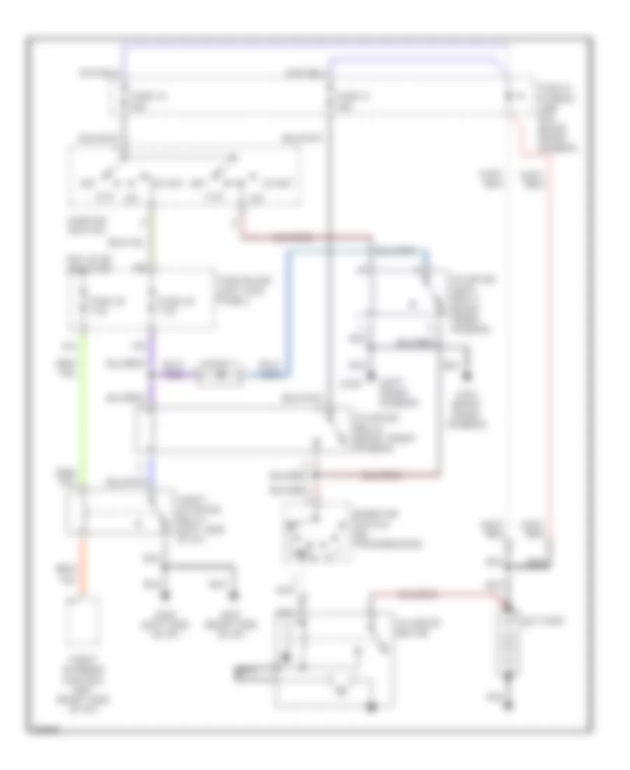
3.0L, Engine Performance Wiring Diagrams (1 of 3) for Infiniti J30 1997
List of elements for 3.0L, Engine Performance Wiring Diagrams (1 of 3) for Infiniti J30 1997:
- (rear of engine)
- (right front of engine compt)
- (right front of trunk)
- 08/27/96
- 56a
- 57a
- A/c system
- Acc
- Box)
- Cooling fan system
- Dropping resistor (right rear of trunk)
- Eccs relay (in relay & fuse
- Engine control module (right kick panel)
- Fuel pump (in fuel tank)
- Fuel pump control module (right rear of trunk)
- Fuel pump relay (above left kick panel)
- Fuse 15a
- Fuse 7.5a
- Fuse and fusible link box
- Fuse block (in j/b)
- Fuse block (j/b)
- G100
- G115
- G401
- Hot at all
- Hot at all times
- Hot in start
- Iacv-aac valve
- Iacv-air regulator
- Iacv-ficd solenoid valve
- Ignition switch
- Instrument cluster system
- Intake air temperature sensor (left front corner of eng compt)
- J/c 13 (right front of trunk)
- Knock sensor (center rear of engine)
- Nca
- Off
- Or on
- Pnk
- Power steering oil pressure switch (on power steering high pressure line)
- Power transistor unit (top right front of engine)
- Start
- Times
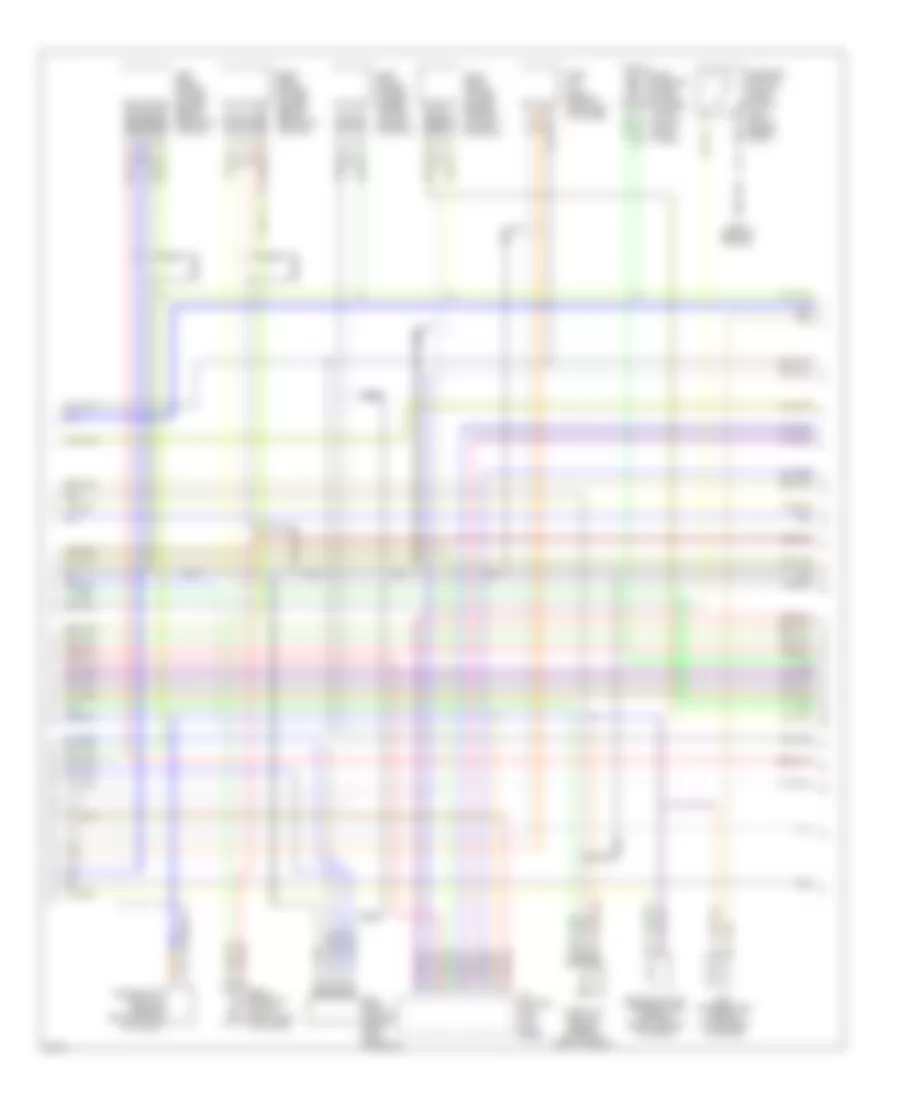
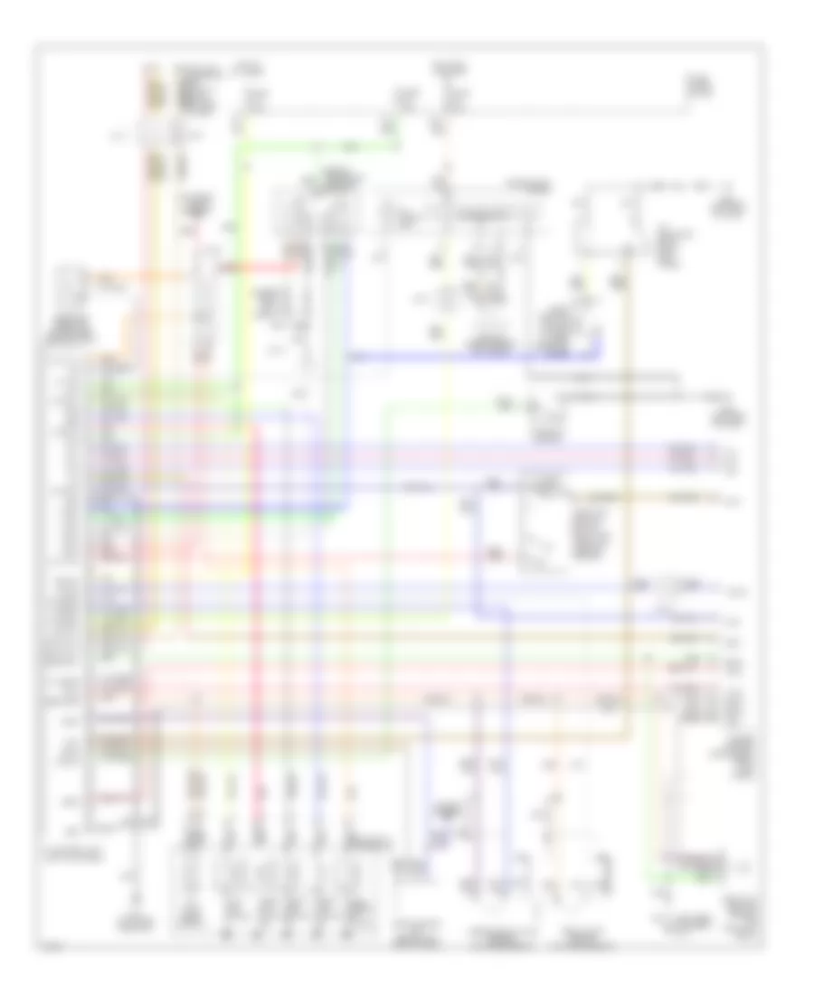
3.0L, Engine Performance Wiring Diagrams (2 of 3) for Infiniti J30 1997
List of elements for 3.0L, Engine Performance Wiring Diagrams (2 of 3) for Infiniti J30 1997:
- A/t control unit (left kick panel)
- Cam- shaft position sensor (left front of engine)
- Canister control vacuum check switch (left side of engine compt)
- Crankshaft position sensor (center rear of engine)
- Egr temperature sensor (top center of engine)
- Egrc solenoid valve (left front of engine)
- Engine coolant temperature sensor (front center of engine)
- Evap canister purge control solenoid valve (on left strut tower)
- G115 (rear of engine)
- Left front heated oxygen sensor (on left exhaust manifold)
- Left rear heated oxygen sensor (below center of vehicle)
- Mass air flow sensor (left side of engine)
- Nca
- Right front heated oxygen sensor (on right exhaust manifold)
- Right rear heated oxygen sensor (below center of vehicle)
- Throttle position sensor (on side of throttle body)
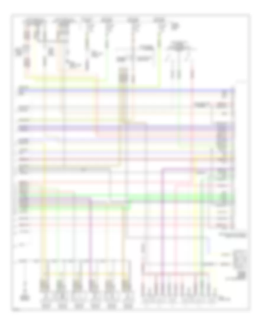
3.0L, Engine Performance Wiring Diagrams (3 of 3) for Infiniti J30 1997
List of elements for 3.0L, Engine Performance Wiring Diagrams (3 of 3) for Infiniti J30 1997:
- (left front of engine) throttle position switch
- (left side of i/p) data link connector (for consult)
- (left side of i/p) data link connector (for gst)
- 25a
- 64a
- Cluster
- Defogger system
- Engine control module (right kick panel)
- Fuel injectors
- Fuse 15a
- Fuse 7.5a
- Fuse block (j/b)
- G115 (rear of engine)
- G202 (left side of i/p)
- Hot at all times
- Hot in on or start
- Ignition coil #1
- Ignition coil #2
- Ignition coil #3
- Ignition coil #4
- Ignition coil #5
- Ignition coil #6
- Instrument
- J/c 11 (right side of i/p)
- J/c 7 (left kick panel)
- J/c 9 (left side of i/p)
- Malfunction indicator
- Speedo- meter
- Vehicle speed sensor (on transmission)
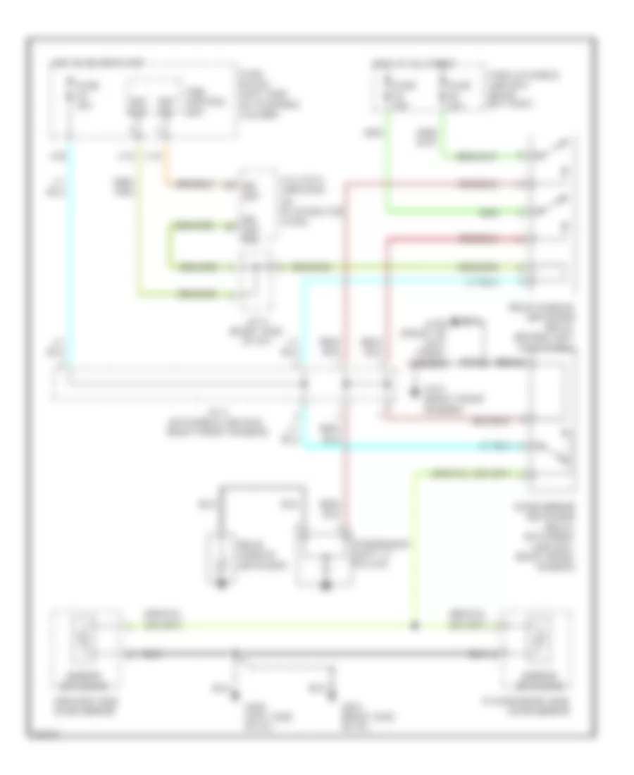
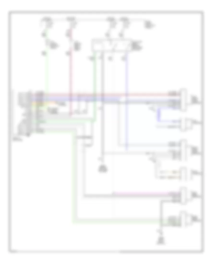
EXTERIOR LIGHTS
Back-up Lamps Wiring Diagram for Infiniti J30 1997
List of elements for Back-up Lamps Wiring Diagram for Infiniti J30 1997:
- (center rear of luggage compt)
- (left rear wheelwell)
- (right front of luggage compt)
- 15g
- 2-1
- Fuse 30 7.5a
- Fuse block
- G401
- G407
- Hot in run or start
- Inhibitor switch
- J/c-12
- Left back-up light
- Red
- Right back-up light
Exterior Lamps Wiring Diagram (1 of 2) for Infiniti J30 1997
List of elements for Exterior Lamps Wiring Diagram (1 of 2) for Infiniti J30 1997:
- (center rear of luggage compt)
- (left front engine compt) j/c-2
- (left front fender)
- (left i/p)
- (left rear wheelwell)
- (right front fender)
- (right front luggage compt)
- (right front of luggage compt)
- 11g
- 12e
- 34a
- Fuse & fusible link box
- Fuse 15a
- Fuse 25 7.5a
- Fuse 4 15a
- Fuse block
- G100
- G101
- G309 (left front door sill)
- G401
- G402 (left rear wheel- well)
- G407
- Head
- Headlights system
- High
- Hot at all times
- Instrument cluster system
- J/c-12
- J/c-13
- J/c-6
- Left front clearance light
- Left front side marker light
- Left license light
- Left rear side marker light
- Left rear tail/ stop/ turn lights
- Light
- Light switch
- Mounted
- Nca
- Off
- Park
- Right front clearance light
- Right front side marker light
- Right license light
- Right rear side marker light
- Right rear tail/ stop/ turn lights
- Stop
- Stop and tail lamp sensor (center rear of luggage compartment)
- Stop lamp switch
- Tail lamp relay (left kick panel)
Exterior Lamps Wiring Diagram (2 of 2) for Infiniti J30 1997
List of elements for Exterior Lamps Wiring Diagram (2 of 2) for Infiniti J30 1997:
- 10e
- 13a
- 14a
- 40a
- 53a
- 71a
- 72a
- Combination flasher unit (right of instrument cluster)
- Fuse 1 10a
- Fuse 21 7.5a
- Fuse block
- G100 (left front fender)
- G101 (right front fender)
- G201 (right side of i/p)
- G202 (left side of i/p)
- Hazard
- Hazard switch
- Hot at all times
- Hot in run or start
- Ill.
- Instrument cluster
- Left front turn light
- Left turn ind.
- Multi remote control relay-1 (behind instrument cluster)
- Multi remote control relay-2 (below instrument cluster)
- Multi remote control unit (left rear wheelwell)
- Pnk
- Rheostat
- Right front turn light
- Right turn ind.
- Tail lamp relay
- Turn signal switch
GROUND DISTRIBUTION
Ground Distribution Wiring Diagram for Infiniti J30 1997
List of elements for Ground Distribution Wiring Diagram for Infiniti J30 1997:
- A/c auto amplifer, abs actuator, accessory relay-1, air bag diagnosis sensor unit, ascd control unit, ascd main switch, audio ampifier relay, auto anti-dazzling inside mirror, blower high relay, cigarette lighter, clock, combination flasher unit, combination meter (air bag), combination meter (cruise indicator lamp), combination meter (fuel), combination meter (high beam indicator), combination meter (speedometer), combination meter (tachometer), combination meter (turn), combination meter (water temperature), data link connector for consult, data link connector for gst, door lock timer, door mirror defogger (driver side), door mirror defogger (passenger side), door mirror remote control switch, fan control amplifier, first position switch, front door handle switch (driver side), front door handle switch (passenger side), front door key cylinder switch (driver side), front door key cylinder switch (passenger side), front door lock actuator (driver side) (door unlock sensor), front door lock actuator (passenger side) (door unlock sensor), fuel lid opener switch, glove box lamp (illumination), illumination control switch, intake door motor, kickdown switch, max cold relay, mode door motor, parking position switch, power steering control unit, power window amplifier (passenger side), power window main switch, push control unit, rear door switch relay, receiver control unit, shield wire (front door speaker) (driver side), shield wire (front door speaker) (passenger side), shift lock control unit, shift lock soleniod, spot lamp, sunroof relay, theft warning control unit, theft warning starter relay, time control unit, trunk lid opener switch, vanity mirror illumination (driver side), vanity mirror illumination (passenger side), warning buzzer
- A/c auto amplifier, ascd hold relay, brake fluid level switch, left clearance lamp, right clearance lamp, cooliing fan motor, daytime light control unit (for canada), door mirror defogger relay, left front side marker lamp, right front side marker lamp, left front turn signal lamp, right front turn signal lamp, front wiper motor, front wiper switch, left headlamp (high), left headlamp (low), right headlamp (high), right headlamp (low), headlamp control relay unit, hood switch, lighting switch, park/neutral position relay, power steering oil pressure switch, starter hold relay, triple-pressure switch, washer switch, wiper relay
- Alternator, power steering solenoid valve
- Canister control vacuum check switch, cooling fan motor, crankshaft position sensor, data link connector for gst, eccs control module (ecm), shield wire (crankshaft position sensor), shield wire (left front heated oxygen sensor), shield wire (right front heated oxygen sensor), shield wire (knock sensor), shield wire (mass air flow sensor), shield wire (left rear heated oxygen sensor), shield wire (right rear heated oxygen sensor), shield wire (throttle position sensor), shield wire (crankshaft position sensor (obd ii)), triple-pressure switch
- Dropping resistor, front door switch (passenger side), fuel pump control module (fpcm), fuel tank gauge unit, handset, power seat (passenger side), right rear door lock actuator (door unlock sensor), right rear door switch, right rear power window amplifier, right rear power window sub-switch (illumination), left rear speaker, right rear speaker, seat back heater (passenger side), transceiver unit
- Eccs control module (ecm), ignition coil number 1, ignition coil number 2, ignition coil number 3, ignition coil number 4, ignition coil number 5, ignition coil number 6, power transistor unit
- Front door switch (driver side), high-mounted stop lamp, multi-remote control unit, power antenna timer and motor, power seat (driver side), left rear door lock actuator (door unlock sensor), left rear door switch, left rear power window amplifier, left rear power window sub- switch (illumination), seat back heater (driver side), seat belt buckle switch (driver side),
- G100 (front of left front fender)
- G101 (front of right front fender)
- G102 (left front shock tower)
- G103 (right front shock tower)
- G111 (near battery)
- G114 (left rear of engine)
- G201 (right side of i/p)
- G202 (left side of i/p)
- G309 (left front door sill)
- G400 (left front side of trunk)
- G401 (right front side of trunk)
- G407 (center rear of trunk)
- G904 (left "c" pillar)
- G905 (right "c" pillar)
- Iacv-air regulator
- Left back-up lamp, right back-up lamp, left license lamp, right license lamp, left rear combination lamp, right rear combination lamp, left rear side marker lamp, stop and tail lamp sensor, trunk lid key cylinder switch, trunk room lamp switch
- Left front wheel sensor shield wire
- Right front wheel sensor shield wire
- Shield wire (abs control unit)
- Shield wire (rear wheel sensor)
HEADLIGHTS
Headlight Wiring Diagram, with DRL for Infiniti J30 1997
List of elements for Headlight Wiring Diagram, with DRL for Infiniti J30 1997:
- (left front engine compt)
- (left front fender) g100
- (right front fender) g101
- 11e
- 12e
- 1st
- 25a
- 2nd
- 77a
- Alternator
- Charge ind.
- Control
- Daytime light control unit (left front engine compt)
- Daytime light relay
- Diode (left i/p)
- Engine compt)
- Exterior lights system
- Ftp
- Fuse & fusible link box (right side engine compt)
- Fuse & fusible link box (right side of engine compt)
- Fuse 15a
- Fuse 20 7.5a
- Fuse 24 7.5a
- Fuse 31 7.5a
- Fuse 7.5a
- Fuse block
- G201 (right i/p)
- G202 (left i/p)
- Headlamp
- Hi beam ind.
- Hot at all times
- Hot in run or start
- Hot in start
- Instrument cluster
- J/c-1 (right front engine compt)
- J/c-2
- J/c-2 (left front engine compt)
- J/c-7 (left i/p)
- Left hi beam headlamp
- Left lo beam headlamp
- Light switch
- Off
- Parking brake switch
- Relay unit (left rear
- Right hi beam headlamp
- Right lo beam headlamp
- Tail lamp relay (left kick panel)
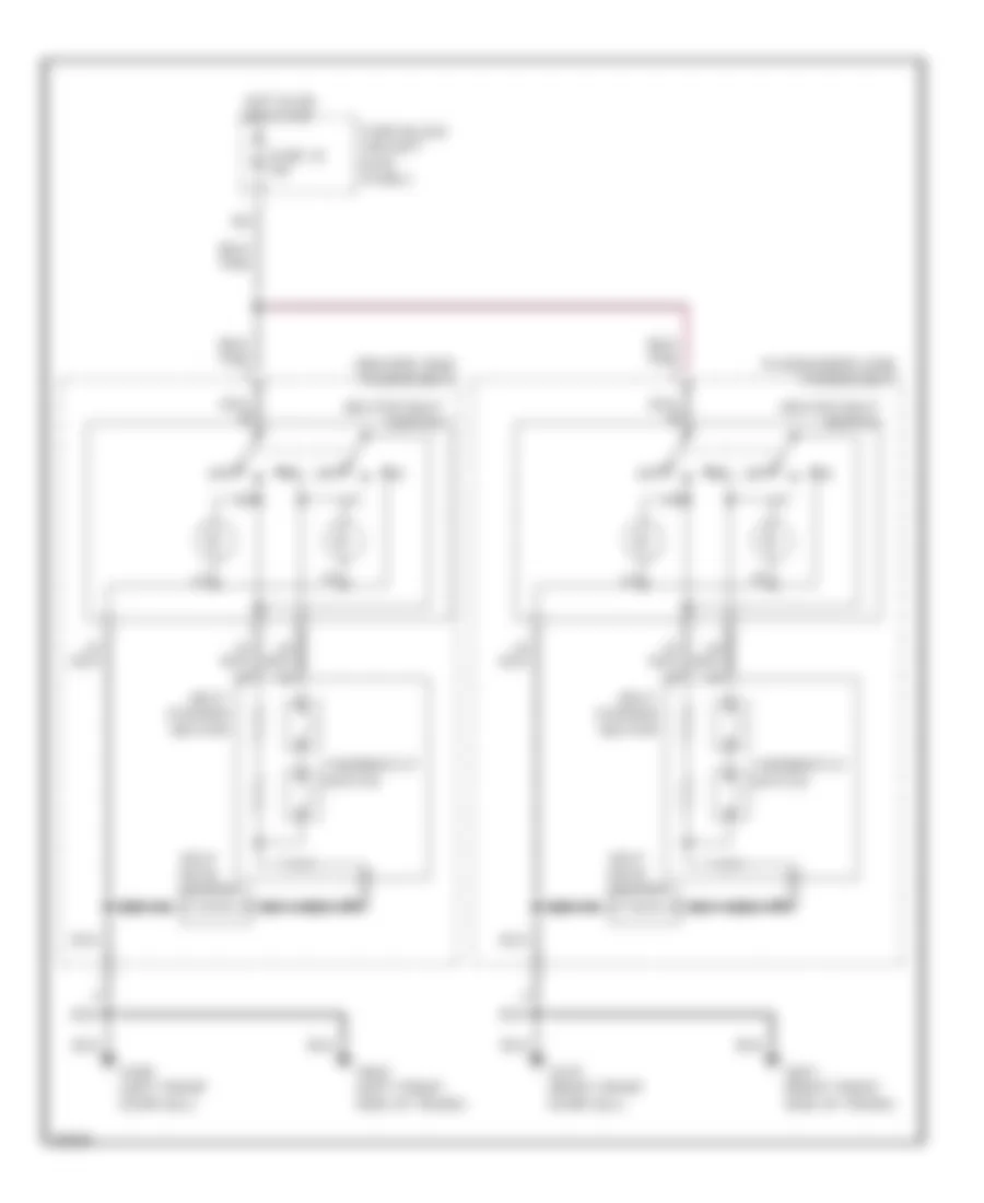
Headlight Wiring Diagram, without DRL for Infiniti J30 1997
List of elements for Headlight Wiring Diagram, without DRL for Infiniti J30 1997:
- (left front engine compt)
- (left rear of engine compt)
- 12e
- 1st
- 2nd
- Control
- Exterior lights system
- Ftp
- Fuse & fusible link box (right side engine compt)
- Fuse 15a
- Fuse 7.5a
- G100 (left front fender)
- G101 (right front fender)
- G201 (right i/p)
- G202 (left i/p)
- Headlamp
- Hec (left kick panel)
- Hi beam ind.
- Hot at all times
- Instrument cluster
- J/c-1 (right front engine compt)
- J/c-2
- J/c-2 (left front engine compt)
- Left hi beam headlamp
- Left lo beam headlamp
- Light switch
- Off
- Relay unit
- Right hi beam headlamp
- Right lo beam headlamp
- Tail lamp relay (left kick panel)
HORN
Horn Wiring Diagram for Infiniti J30 1997
List of elements for Horn Wiring Diagram for Infiniti J30 1997:
- Diode (left side of dash)
- Fuse & fusible link box (right front fender)
- Fuse 55 15a
- Horn relay (relay box, right front fender)
- Horn switch
- Hot at all times
- J/c 3 (fuse & fusible link box, right front fender)
- J/c 8 (behind center console)
- Low pitch horn (front center of engine compartment)
- Nca
- Theft warning control unit (right side of dash)
- Theft warning horn (front center of engine compartment)
INSTRUMENT CLUSTER
Instrument Cluster Wiring Diagram (1 of 2) for Infiniti J30 1997
List of elements for Instrument Cluster Wiring Diagram (1 of 2) for Infiniti J30 1997:
- (left dash)
- (lower left rear of engine)
- (mil)
- 21a
- 25a
- 43a
- A-1
- A-10
- A-2
- A-3
- A-4
- A-5
- A-6
- A-7
- A-8
- A-9
- A/t
- A/t check ind.
- Abs control unit (center rear of trunk)
- Abs ind.
- Air bag diagnosis sensor unit (below center console)
- Air bag ind.
- Alternator
- Anti-lock brakes system
- B-11
- B-12
- B-13
- B-14
- B-15
- B-16
- B-17
- B-18
- Bat
- Brake fluid level switch (on master cylinder)
- Brake ind.
- C-19
- C-20
- C-21
- C-22
- C-23
- C-24
- C-25
- C-26
- C-27
- C-28
- C-29
- C-30
- Charge ind.
- Check connector
- Check engine ind.
- Clock
- Control
- Cruise ind.
- D-31
- D-32
- D-33
- D-34
- D-35
- Diode (left dash)
- Door ind.
- Engine control module (behind center console)
- Exterior
- Exterior lights system
- Fuel gauge
- Fuel ind.
- Fuse 13 7.5a
- Fuse 31 7.5a
- Fuse block
- G100 (front of left front fender)
- G101 (front of right front fender)
- G201 (right side of dash)
- G202 (left side of dash)
- Gnd
- Head- lights system
- Hi beam ind.
- Hicas ind.
- Hot at all times
- Hot in run or start
- Ign
- Instrument cluster
- Interior lights system
- J/c 7 (left kick panel)
- J/c-10 (center dash)
- J/c-7
- Left turn ind.
- Lights system
- Meter illum.
- Oil ind.
- Oil pressure switch
- Panel)
- Parking brake switch
- Right turn ind.
- Seat belt ind.
- Security ind.
- Speed- ometer
- Tach- ometer
- Tail ind.
- Temp. gauge
- Theft warning control unit (behind center console)
- Unit (left kick
- Vehicle speed sensor (on transmission)
- Washer ind.
- Washer level switch
Instrument Cluster Wiring Diagram (2 of 2) for Infiniti J30 1997
List of elements for Instrument Cluster Wiring Diagram (2 of 2) for Infiniti J30 1997:
- "c"
- (a/t only)
- (behind
- (center dash)
- (left dash)
- (left kick
- 60a
- A/c auto amplifier (behind center
- A/t control unit
- Ascd control unit
- Check
- Connector (left dash)
- Console)
- Control
- Fuel tank gauge unit
- Fuse 23 7.5a
- Fuse 26 7.5a
- Fuse block
- G300 (below left front seat)
- G400 (left front side of trunk)
- G401 (right front side of trunk)
- G904 (left
- Hot at all times
- Hot w/ park lights on
- J/c 8 (left kick panel)
- J/c-10
- J/c-6
- Left front door switch
- Left rear door switch
- Panel)
- Pillar)
- Power
- Rear door switch relay
- Rear seat)
- Right front door switch
- Right rear door switch
- Steering
- Stop & tail lamp sensor (center rear of trunk)
- Thermal transmitter (left side of engine)
- Unit
INTERIOR LIGHTS
Courtesy Lamps Wiring Diagram for Infiniti J30 1997
List of elements for Courtesy Lamps Wiring Diagram for Infiniti J30 1997:
- "c"
- (behind
- (right of
- 11a
- 58a
- 59a
- 60a
- Cluster)
- Diode (right i/p)
- Door
- Fuse 23 7.5a
- Fuse block (left kick panel)
- G100 (left front fender)
- G101 (right front fender)
- G201 (right i/p)
- G202 (left i/p)
- G309 (left front door sill)
- G401 (right front side of trunk)
- G404 (left rear side of trunk)
- G407 (center rear of trunk)
- G904 (left
- Head
- Hot at all times
- Instrument
- Interior light
- J/c-10 (behind center of i/p)
- J/c-13 (right front luggage compt)
- Key ill.
- Left footwell lamp
- Left front door handle switch
- Left front door switch
- Left front step lamp
- Left rear door switch
- Left rear step lamp
- Left vanity mirror ill.
- Light switch
- Multi- remote control unit (left rear wheelwell)
- Nca
- Off
- Park
- Pillar)
- Rear door switch relay
- Rear seat)
- Right footwell lamp
- Right front door handle switch
- Right front door switch
- Right front step lamp
- Right rear door switch
- Right rear step lamp
- Right vanity mirror ill.
- Spot light
- Theft warning control unit
- Time control unit
- Trunk room lamp
- Trunk room lamp switch
Instrument Illumination Wiring Diagram for Infiniti J30 1997
List of elements for Instrument Illumination Wiring Diagram for Infiniti J30 1997:
- (left rear wheelwell)
- (right rear wheelwell)
- 11g
- 16a
- 17a
- 18a
- 19a
- 1st
- 20a
- 2nd
- A/t indicator illum
- Ascd main switch
- Auto anti- dazzling inside mirror
- Cd player and radio
- Cigarette lighter
- Clock
- Fuse & fusible link box (right side engine compt)
- Fuse 15a
- Fuse 25 7.5a
- Fuse 26 7.5a
- Fuse block (left kick panel)
- G100 (left front fender)
- G101 (right front fender)
- G201 (right side of dash)
- G201 (right side of i/p)
- G202 (left side of dash)
- G202 (left side of i/p)
- G309 (left front door sill)
- G400 (left front side of trunk)
- G401 (right front side of trunk)
- G904 (left"c" pillar)
- Glove box lamp
- Hazard switch
- Hot at all times
- Ill.
- Illumination control switch
- Instru- ment cluster
- J/c-11 (behind center of i/p)
- J/c-12
- J/c-13
- J/c-6 (left side of i/p)
- J/c-7 (left side of i/p)
- J/c-8 (left kick panel)
- Left rear power window switch
- Light switch
- Off
- Power window main switch
- Power window sub-switch
- Push control unit
- Right rear power window switch
- Tail lamp relay (left kick panel)
POWER ANTENNA
Power Antenna Wiring Diagram for Infiniti J30 1997
List of elements for Power Antenna Wiring Diagram for Infiniti J30 1997:
- 10a
- 66a
- 7.5a
- Antenna timer (left rear quarter panel)
- Fuse 13
- Fuse 9
- Fuse block (left kick panel)
- G309 (left front door sill)
- G400 (left side of trunk)
- Hot at all times
- J/c 7 (left kick panel)
- Nca
- Power antenna motor (left rear quarter panel)
- Radio
POWER DISTRIBUTION
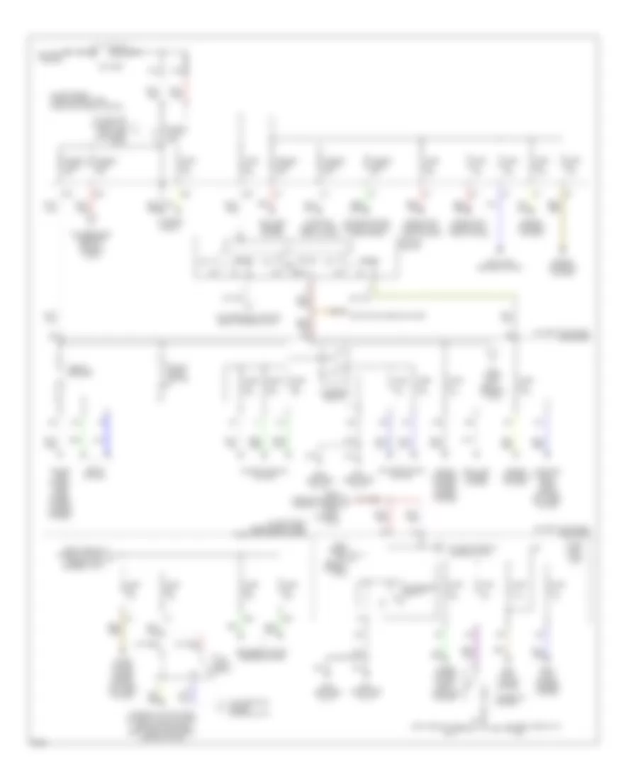
Power Distribution Wiring Diagram (1 of 2) for Infiniti J30 1997
List of elements for Power Distribution Wiring Diagram (1 of 2) for Infiniti J30 1997:
- (in left front inner fender panel) fuse and fusible link box
- (left side of i/p) g202
- (on left kick panel) fuse block
- (right side of i/p) g201
- A29
- A37
- A41
- A42
- A43
- A44
- A46
- A48
- A50
- A57
- A65
- A66
- A80
- Acc
- Accessory relay-1
- Accessory relay-2
- Air condi- tioning system
- Air conditioning system
- Air conditioning system, cooling fans system
- Anti- theft system, mirrors system
- Anti-lock brakes system
- Battery
- Battery ground
- Cellular phones system
- Charging circuit
- Cigarette lighter
- Circuit breaker
- Defogger system, mirrors system
- E11
- E55
- Engine controls system
- From acces- ory d relay-2 (diagram 1 of 2)
- From fuse and fusible link box, a fusible link a (diagram 1 of 1)
- From fuse and fusible link box, fusible link f (diagram 1 of 2)
- Fuse 10a
- Fuse 15a
- Fuse 20a
- Fuse 7.5a
- Fusible link a 100a
- Fusible link b 25a
- Fusible link c 30a
- Fusible link d 30a
- Fusible link e 45a
- Fusible link f 75a
- G201 (right side of i/p)
- G202 (left side of i/p)
- Headlights system, anti- theft system
- Horns system, cruise control system, anti-theft system
- Ignition switch
- Interior lights system, exterior lights system, headlights system, body computer system, mirrors system
- Nca
- Off
- Power tops system, door locks system, power windows system
- Power windows system
- Red
- Seats system
- Short conn- ector
- Sound systems system, power antenna system
- Start
- Starting circuit, anti- theft system
- Starting circuit, head- lights system, anti-theft system
- Starting/charging system
- Tail lamp relay
- Time con- trol unit
- To acces- ory relay-1 (diagram 1 of 2)
- To fuse and fusible link box, fuse 55 (diagram 1 of 1)
- To fuse block, accessory relay-1 (diagram 1 of 2)
- To fuse block, fuse 25 (diagram 2 of 2)
- To fuse block, ignition relay (diagram 2 of 2)
- To ignition relay (diagram 2 of 2)
- Wiper/ washer system, body computer system
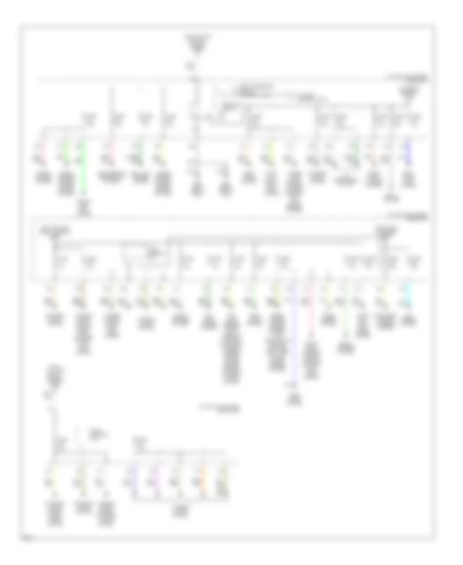
Power Distribution Wiring Diagram (2 of 2) for Infiniti J30 1997
List of elements for Power Distribution Wiring Diagram (2 of 2) for Infiniti J30 1997:
- (on left kick panel) fuse block
- A16
- A17
- A18
- A19
- A20
- A21
- A22
- A25
- A26
- A38
- A39
- A40
- A53
- A54
- A55
- A56
- A58
- A59
- A60
- A64
- A69
- A70
- A73
- A74
- A77
- A79
- A80
- Air conditioning system
- Anti- lock brakes system, shift interlock system, electronic power steering system, cruise control system, exterior lights system
- Cell- ular phones system
- Cellular phones system
- Cruise control system
- Cruise control system, engine control system
- De- fogger system
- Door locks system
- E12
- E15
- Electronic power steering system
- Engine con- trol system
- Exterior lights system
- Exterior lights system, head- lights system
- From accessory relay-1 (diagram 1 of 2)
- From fuse 37 (diagram 2 of 2)
- From ignition relay (diagram 2 of 2)
- From ignition switch (diagram 1 of 2)
- From tail lamp relay (diagram 1 of 2)
- Fuse 10a
- Fuse 15a
- Fuse 20a
- Fuse 3a
- Fuse 7.5a
- G10
- G11
- G15
- G201 (right side of i/p)
- G202 (left side of i/p)
- Head- lights system
- Horns system, power antenna system, air conditioning system, computer data lines system, sound systems system
- Ignition relay
- Instru- ment cluster system
- Instru- ment cluster system, warning systems, anti- theft system
- Interior lights system
- Interior lights system, anti- theft system
- Interior lights system, exterior lights system
- Interior lights system, instru- ment cluster system, anti- theft system
- Power tops system, power windows system, anti- lock brakes system
- Seats system
- Shift inter- lock system
- Sound systems system
- Start- ing circuit, anti- theft system
- Time control unit
- To fuse 1 (diagram 2 of 2)
- To fuse 32 (diagram 2 of 2)
- Trans- mission system
- Trans- missions system, cruise control system
- Trunk, tail- gate, fuel doors system
POWER DOOR LOCKS
Power Door Lock Wiring Diagram (1 of 2) for Infiniti J30 1997
List of elements for Power Door Lock Wiring Diagram (1 of 2) for Infiniti J30 1997:
- stroke & normal
- stroke & normal unlock-between full
- (behind
- (behind right side of i/p)
- (center rear of trunk lid)
- (right front of trunk)
- 10g
- 22a
- 28a
- 46a
- 58a
- 60a
- Circuit breaker-1
- Cylinder tamper switch
- Diode
- Door
- Door lock timer (behind left i/p)
- Driver's side door lock key switch, door unlock
- Feeder cable
- Fuse 10a
- Fuse 15a
- Fuse 7.5a
- Fuse block
- G201
- G202
- G309 (left front door sill)
- G401 (right front side of trunk)
- G403 (left rear wheel- well)
- G407 (center rear of trunk)
- Hot at all times
- Interior light
- Interior lights system (rheostat)
- J/c 10 (behind right side of i/p)
- J/c 6 (left kick panel)
- J/c-13
- J/c-13 (right front of trunk)
- Key
- Key cylinder withdrawn
- Key switch & key
- Key switch, door unlock
- Left side
- Lock
- Lock-between full
- Main switch
- Of i/p)
- Off
- Passenger's side door lock
- Pnk
- Red
- Remote control relays 1 & 2 (exterior lights system)
- Remote control unit (left rear of trunk)
- Right side
- Switch
- Switch (in glove box)
- Theft warning control unit
- Trunk lid opener cancel
- Trunk lid opener solenoid (center rear of trunk)
- Trunk room lamp switch
- Trunk/ fuel lid opener switch
- Un- lock
- Window antenna
Power Door Lock Wiring Diagram (2 of 2) for Infiniti J30 1997
List of elements for Power Door Lock Wiring Diagram (2 of 2) for Infiniti J30 1997:
- (behind center of i/p) j/c-10
- Between
- Door lock status
- G316 (right front door sill)
- G401 (right front side of trunk)
- Left front door lock actuator
- Left front door switch
- Left rear door lock actuator
- Left rear door switch
- Lock
- Lock knob
- Locked
- Locked & unlocked
- Pnk
- Rear door switch relay (behind center of i/p)
- Right front door lock actuator
- Right front door switch
- Right rear door lock actuator
- Right rear door switch
- Switch
- Un- lock
- Unlocked
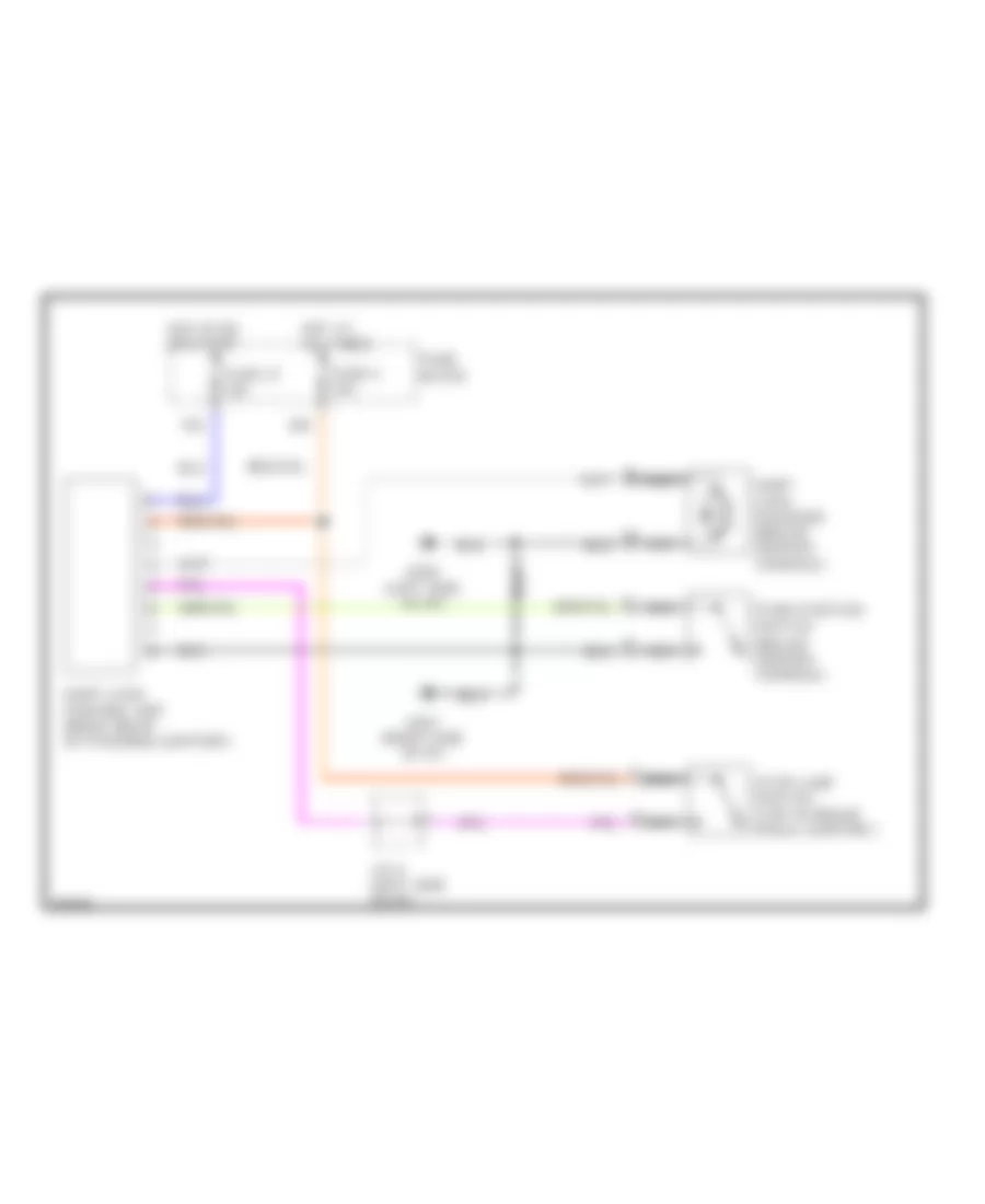
POWER MIRRORS
Auto Anti-dazzling Inside Mirror for Infiniti J30 1997
List of elements for Auto Anti-dazzling Inside Mirror for Infiniti J30 1997:
- (+)
- (-)
- A16
- A25
- Auto anti- dazzling inside mirror
- Fuse 7.5a
- Fuse block (on left kick panel)
- G201 (right side of i/p)
- G202 (left side of i/p)
- Hot in on or start
- Hot in park or head
- Ill
- Ill cont
- Interior lights system
- Joint connector 8 (left end of dash)
Power Mirror Wiring Diagram for Infiniti J30 1997
List of elements for Power Mirror Wiring Diagram for Infiniti J30 1997:
- A50
- Change over switch
- Defogger system (door mirror defogger relay)
- Door mirror remote control switch
- Driver's side door mirror actuator
- Fuse 8 10a
- Fuse block (on left kick panel)
- G201 (right side of i/p)
- G202 (left side of) i/p)
- Hot in acc or on
- Left/right motor
- Mirror heater
- Mirror switch
- Passenger's side door mirror actuator
- Up/down motor
POWER SEATS
Heated Seats Wiring Diagram for Infiniti J30 1997
List of elements for Heated Seats Wiring Diagram for Infiniti J30 1997:
- Driver's side power seat
- Fuse 33 15a
- Fuse block (on left kick panel)
- G309 (left front door sill)
- G316 (right front door sill)
- G400 (left front side of trunk)
- G401 (right front side of trunk)
- Heated seat switch
- Hot in on or start
- Nca
- Nca b
- Off
- Passenger's side power seat
- Seat back heater
- Seat cushion heater
- Thermostat switch
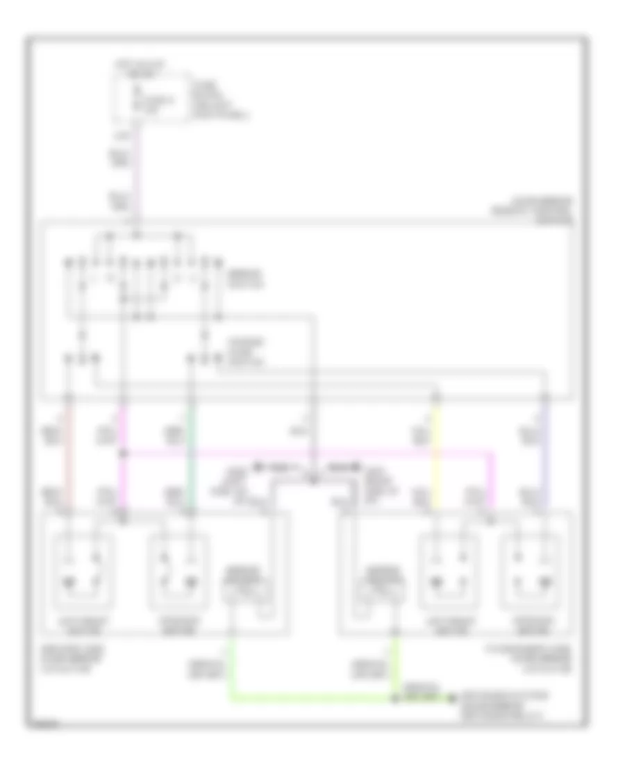
Power Seats Wiring Diagram for Infiniti J30 1997
List of elements for Power Seats Wiring Diagram for Infiniti J30 1997:
- (left seat)
- (left seat) f6
- (right seat)
- (right seat) a42
- Circuit breaker
- Control unit
- Door sill) door sill)
- Down
- El10 (right seat)
- El11
- El12
- El13
- El14
- El3 (left seat)
- El4
- El5
- El6
- El7
- Front lifter
- Front limit switch
- Front motor
- Fully down
- Fully front
- Fully rear
- Fully up
- Fuse block (on left kick panel)
- G309 (left g316 (right seat) (right front
- G400 (left g401 seat) (right (left seat) front (right side of front trunk) side of trunk)
- Hot at all times
- Lifting device
- Limit switch
- Motor
- Nca
- Other
- Power seat
- Power seat switch
- Rear lifter
- Rear limit switch
- Rear motor
- Recline
- Reclining device
- Seat) (left front
- Slide
- Sliding device
POWER TOP/SUNROOF
Power Top/Sunroof Wiring Diagrams for Infiniti J30 1997
List of elements for Power Top/Sunroof Wiring Diagrams for Infiniti J30 1997:
- 46a
- 73a
- Circuit breaker 2
- Closed
- Down
- Down/ open relay
- Full closed
- Full open
- Full tilt-down
- Full tilt-up
- Fuse 7.5a
- Fuse block
- G201 (right side of dash)
- G202 (left side of dash)
- Hot at all times
- Hot in on or start
- J/c 8 (left side of dash)
- Limit switch 1
- Limit switch 2
- Nca
- Open
- Red
- Slide switch
- Sunroof motor
- Sunroof motor assembly (center front of roof)
- Sunroof relay (right side of dash)
- Sunroof switch
- Tilt switch
- Up/ close relay
POWER WINDOWS
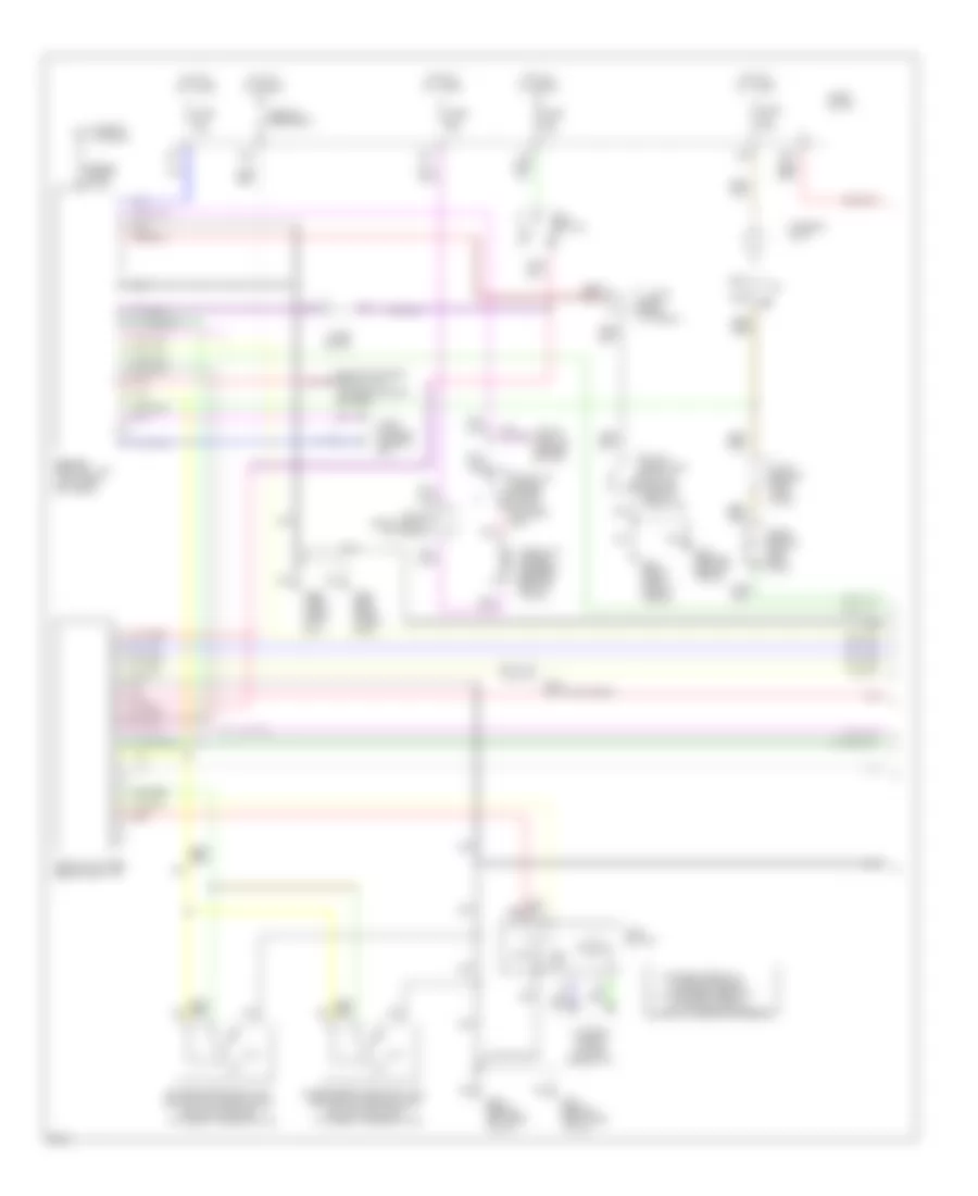
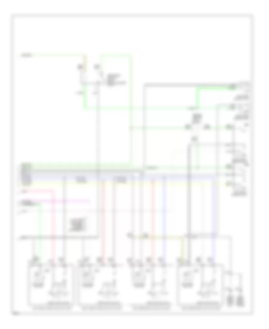
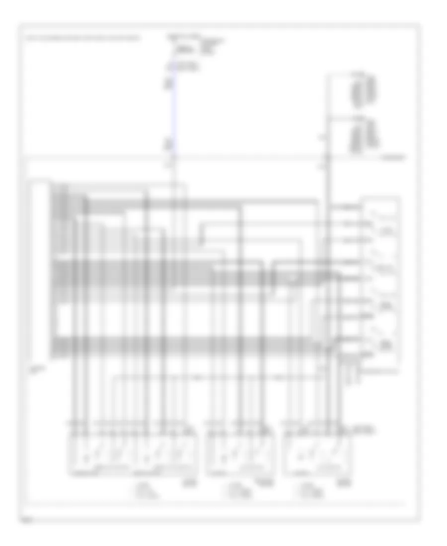
Power Window Wiring Diagram for Infiniti J30 1997
List of elements for Power Window Wiring Diagram for Infiniti J30 1997:
- (left side of i/p) g202
- (right side of i/p) g201
- A37
- A41
- A46
- A73
- Bat
- Circuit breaker
- D16
- D17
- Data sig (left rear)
- Data sig (right front)
- Data sig (right rear)
- Dn pwr srce
- Down
- Down sw
- Fuse 20a
- Fuse 7.5a
- Fuse block (left kick panel)
- G201 (right side of i/p)
- G202 (left side of i/p)
- G300 (below left front seat)
- G301 (below right front seat)
- G400 (left front side of trunk)
- G401 (right front side of trunk)
- Gnd
- Ground
- Hot at all times
- Hot in on or start
- Illumination
- Interior lights system
- J/c 10 (right side of dash)
- J/c 8 (left side of i/p)
- Left front power window reg- ulator
- Left rear power window amp (left rear door)
- Left rear power window regulator
- Left rear power window switch
- Nca
- P/w lock
- Power window main switch
- Pwr srce (bat)
- Pwr srce (igniton)
- Pwr win lock sig
- Right front power window amp (right front door)
- Right front power window regulator
- Right front power window switch
- Right rear power window amp (right rear door)
- Right rear power window regulator
- Right rear power window switch
- Sw com
- U/d signal
- Up pwr srce
- Up sw
RADIO
Radio Wiring Diagrams for Infiniti J30 1997
List of elements for Radio Wiring Diagrams for Infiniti J30 1997:
- 66a
- Acc
- Antenna sig
- Audio amp relay (behind right side of dash)
- Battery
- Fr lh (+) amp
- Fr lh (-) amp
- Fr rh (+) amp
- Fr rh (-) amp
- Fuse 10a
- Fuse 15a
- Fuse 7.5a
- Fuse block (left kick panel)
- G202 (behind left side of dash)
- G316 (right front door sill)
- Ground
- Hot at all times
- Hot in on or acc
- Illum
- Interior lights system
- Jc-11 (behind right side of dash)
- Jc-7 (upper left kick panel)
- Left front door speaker
- Left rear speaker
- Left tweeter
- Nca
- On signal
- Power antenna
- Radio & cd player
- Right front door speaker
- Right rear speaker
- Right tweeter
- Rr lh (+) amp
- Rr lh (-) amp
- Rr rh (+) amp
- Rr rh (-) amp
SHIFT INTERLOCKS
Shift Interlock Wiring Diagram for Infiniti J30 1997
List of elements for Shift Interlock Wiring Diagram for Infiniti J30 1997:
- (below center console)
- 39a
- 70a
- Fuse 37 10a
- Fuse 4 15a
- Fuse block
- G201 (right side of i/p)
- G202 (left side of i/p)
- Hot at all times
- Hot in on or start
- J/c 6 (left side of i/p)
- Nca
- Park position switch
- Shift lock control unit (right rear of steering support)
- Shift lock solenoid (below center console)
- Stop lamp switch (top of brake pedal support)
STARTING/CHARGING
Charging Wiring Diagram for Infiniti J30 1997
List of elements for Charging Wiring Diagram for Infiniti J30 1997:
- (right front of engine)
- Alternator
- Battery
- Charge indicator
- Fuse & fusible link box (left front fender)
- Fuse 10a
- Fuse 31 7.5a
- Fuse block (left kick panel)
- Fusible link a 100a
- G101 (right front fender)
- Hot in on or start
- Instrument cluster
- J/c 7 (left side of i/p)
- Nca
- Starter motor
Starting Wiring Diagram for Infiniti J30 1997
List of elements for Starting Wiring Diagram for Infiniti J30 1997:
- (left front fender)
- 11e
- 74a
- Acc
- Battery
- Diode 3
- Fuse & fusible link box (right front fender)
- Fuse 20 7.5a
- Fuse 24 7.5a
- Fuse 61 20a
- Fuse block (left kick panel)
- Fuse d 30a
- G100
- G101 (right front fender)
- G201 (right side of i/p)
- G202 (left side of i/p)
- Hot in on or start
- Ignition switch
- Inhibitor switch (on transmission)
- Nca
- Off
- Red/
- Start
- Starter hold relay (right front fender)
- Starter motor
- Starter relay (right front fender)
- Theft starter relay (left side of i/p)
- Theft warning control unit (right side of i/p)
SUPPLEMENTAL RESTRAINTS
Supplemental Restraint Wiring Diagram for Infiniti J30 1997
List of elements for Supplemental Restraint Wiring Diagram for Infiniti J30 1997:
- (base of left b pillar)
- (left side (of i/p) j/c 6
- (right side (of i/p) j/c 9
- 25a
- 79a
- Air bag diagnosis sensor unit (below center console)
- Air bag ind.
- Belt sw
- Data link connector (left side of i/p)
- Dr sw
- Driver's air bag module
- Driver's door switch
- Driver's side seat belt pre-tensioner (base of left b-pillar)
- Fuse 29 10a
- Fuse 31 7.5a
- Fuse block
- G202 (left side of dash)
- G309 (left front door sill)
- Gnd
- Hot in on or start
- Ign
- Instrument cluster
- J/c 11 (right side (of i/p)
- Led
- Nca
- Passenger's air bag module 1
- Passenger's air bag module 2
- Passenger's side seat belt pre-tensioner (base of right b-pillar)
- Seat belt buckle switch (in belt buckle)
- Seat belt ind.
- Spiral cable
- Sq as1 +
- Sq as1 -
- Sq as2 +
- Sq as2 -
- Sq dr +
- Sq dr -
- Sq pas +
- Sq pas -
- Sq pdr +
- Sq pdr -
- Sss clk
- Sss rx
- Sss tx
- Warn lp
TRANSMISSION
A/T Wiring Diagram for Infiniti J30 1997
List of elements for A/T Wiring Diagram for Infiniti J30 1997:
- (left kick panel)
- (left rear of engine) g114
- (on transmission)
- (side of transaxle) inhibitor switch
- 1,2-sw
- 1-2
- 1-sw
- 15g
- 25a
- 3-sw
- A/t check ind
- A/t control unit
- A/t fluid temp sensor
- A/t ind
- A/t indicator relay (right kick panel)
- All times
- Ascd
- Ascd control unit (behind left side of dash)
- Atck
- Automatic transaxle
- Closed throttle
- Combination meter
- Cruise control
- D-sw
- Data clk
- Data in
- Data link connector (for consult) (below left side of dash)
- Data out
- Diodes (left kick panel)
- Dropping resistor (on bracket, near battery)
- Dt1
- Dt2
- Dt3
- Engine control module (ecm) (right kick panel)
- Exterior lights (backup)
- First position switch (at base of gear selector lever)
- Full sw
- Fuse 7.5a
- Fuse block (in j/b)
- G131 (on intake manifold)
- G202 (left side of dash)
- Grd
- Grd-a
- Grd-c
- Hot at
- Hot in on or start
- Idle
- Idle sw
- J/c-10
- J/c-11
- J/c-12
- J/c-6
- J/c-9
- K/d sw
- Kickdown switch
- Line press sol valve
- Mem bu
- N-sw
- Nca
- Neut
- O/t sens
- Obd2
- Over- run clutch sol
- Ovr/c s
- Pl dty s
- Pnk
- R-sw
- Red
- Revolution sensor
- Senp
- Sens bat
- Sens grd
- Shift sol valve a
- Shift sol valve b
- Sp sens
- Speedometer
- Ssa
- Ssb
- Swp
- Tacho
- Tcc sol
- Tcc sol valve
- Throttle position sensor (on throttle body)
- Throttle position switch (built into throttle position sensor)
- Trs
- Ts in
- Turbine
- Turbine revolution sensor (on transmission)
- Tvoo
- V ign
- Vehicle speed sensor (on trans)
- Wot
TRUNK, TAILGATE, FUEL DOOR
Trunk & Fuel Door Release Wiring Diagram for Infiniti J30 1997
List of elements for Trunk & Fuel Door Release Wiring Diagram for Infiniti J30 1997:
- 10g
- Fuel filler sw
- Fuel lid opener solenoid (right rear of trunk)
- Fuse 34 15a
- Fuse block (left side of i/p)
- G201 (right side of i/p)
- G202 (left side of i/p)
- Hot at all times
- J/c-13 (behind right side of rear seat)
- Nca
- Pnk
- Remote control unit
- Trunk lid & fuel lid switch
- Trunk lid opener cancel switch (in glove box)
- Trunk lid opener solenoid (center rear of trunk)
- Trunk lid sw
WARNING SYSTEMS
Warning System Wiring Diagrams for Infiniti J30 1997
List of elements for Warning System Wiring Diagrams for Infiniti J30 1997:
- (behind
- (behind instrument cluster)
- (left kick
- 12b
- 21a
- 24a
- 28a
- 60a
- Acc
- Bat
- Brake sw
- Diode (right dash)
- Door locks system
- Door sw
- Fuse & fusible link box (right side engine compt)
- Fuse 12 10a
- Fuse 13 7.5a
- Fuse 23 7.5a
- Fuse 25 7.5a
- Fuse 32 7.5a
- Fuse 56 15a
- Fuse 7 7.5a
- Fuse block
- G100 (front of left front fender)
- G101 (front of right front fender)
- G201 (right side of dash)
- G202 (left side of dash)
- G300 (below left front seat)
- G400 (left front side of trunk)
- G401 (right front side of trunk)
- Gnd
- Head
- Hot at all times
- Hot in 0n or start
- Hot in acc or run
- Ign
- Instrument cluster system
- Int lamp
- Interior
- Interior lights system
- J/c-10 (center dash)
- Key sw
- Key switch
- Left front door switch
- Left rear door switch
- Light sw in
- Light switch
- Lights system
- Off
- Panel)
- Park
- Rear door switch relay
- Rear seat)
- Right front door switch
- Right rear door switch
- Seat belt switch
- Tail lamp relay
- Time control unit
- Warn out
- Warning chime
WIPER/WASHER
Wiper/Washer Wiring Diagram for Infiniti J30 1997
List of elements for Wiper/Washer Wiring Diagram for Infiniti J30 1997:
- 14e
- 82a
- 83a
- 84a
- Fuse 20a
- Fuse block
- G100 (left front fender)
- G101 (right front fender)
- Hot in acc or on
- Int
- Inter- mittent
- J/c 1 (right front of engine)
- Nca
- Off
- Pnk
- Red
- Time control unit
- Wash
- Washer motor (right front of engine compartment)
- Wiper motor (right side of safety wall)
- Wiper relay (fuse & fusible link box, right front fender)
- Wiper switch

 Čeština
 Dansk
Dansk Deutsch
 Ελληνικά
 English
 English
 Español
 Suomi
Suomi Français
 Français
 עברית
עברית Magyar
 Italiano
 日本語
日本語 한국어
한국어 Nederlands
 Polski
 Português
 Português
 Română
 Русский
 Slovenčina
 Slovenščina
 Svenska
 Türkçe
 中文 (中国)