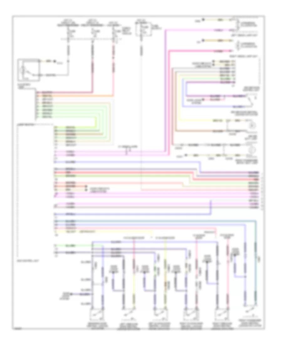
AIR CONDITIONING
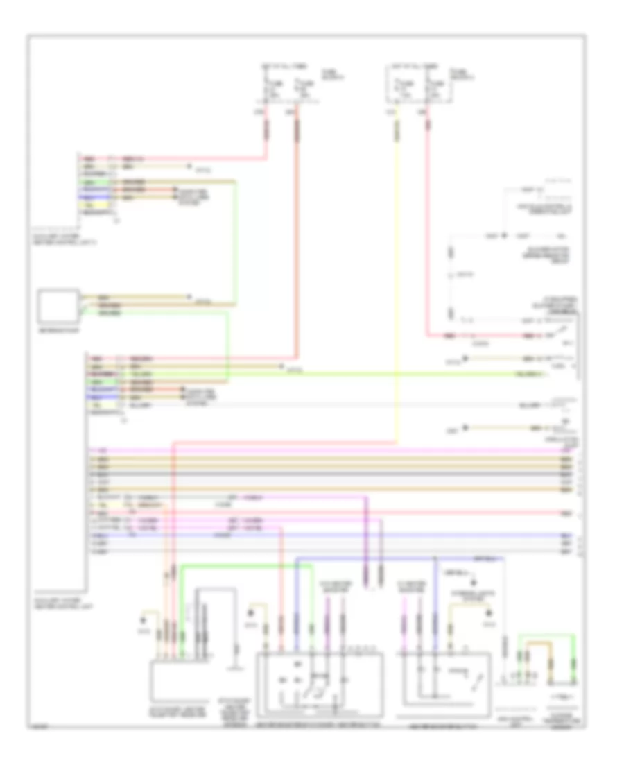
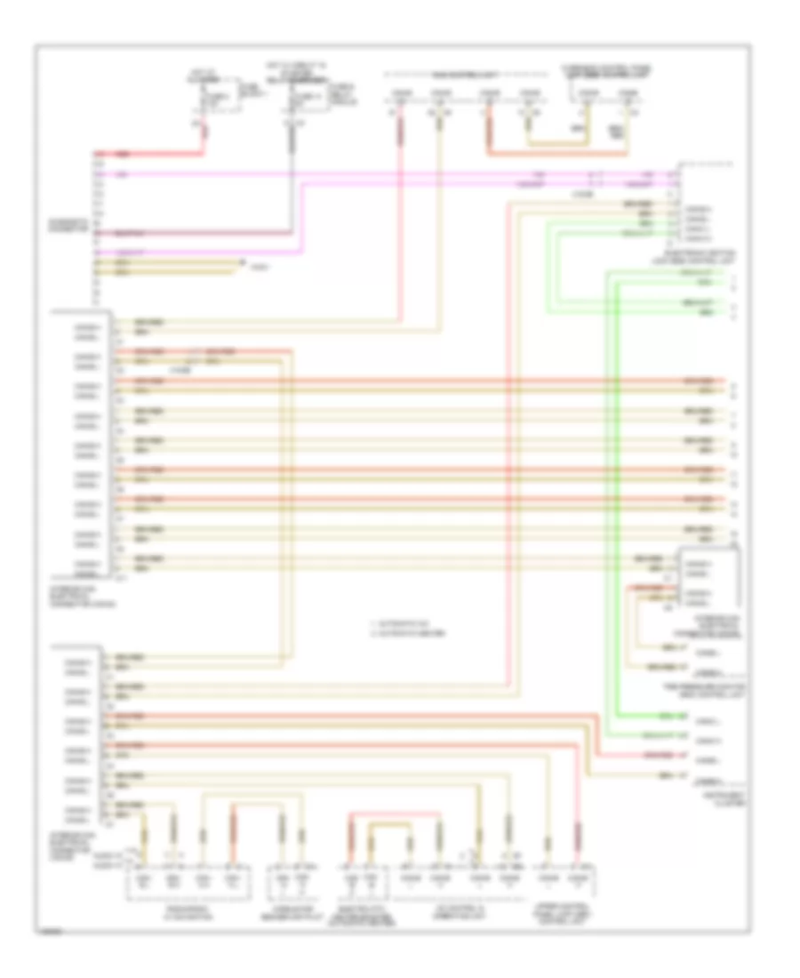
Automatic A/C Wiring Diagram (1 of 4) for Mercedes-Benz Sprinter 2014 2500
 https://portal-diagnostov.com/license.html
Automotive Electricians Portal FZCO
Automotive Electricians Portal FZCO
https://portal-diagnostov.com/license.html
https://portal-diagnostov.com/license.html
Automotive Electricians Portal FZCO
Automotive Electricians Portal FZCO
List of elements for Automatic A/C Wiring Diagram (1 of 4) for Mercedes-Benz Sprinter 2014 2500:
- 16a
- 26/61 (or x26/65)
- 31b
- 42a
- Ac control & operating unit
- Air conditioner 1 additional fan
- Blower motor
- Blower regulator
- Circulation pump
- Computer data lines system
- Flap actuator m
- Flap potentiometer
- Fuse 10a
- Fuse 30a
- Fuse block 2
- Fuse block 6
- Fuse block 7
- Heater blower regulator
- Heater valve motor
- Heater valve potentiometer
- Hot at all times
- Motor
- Nca
- Rear heater/air conditioner air recirculation unit
- Rear heavy duty automatic a/c air recirculation unit
- Red
- Refrigerant compressor
- Refrigerant pressure sensor
- Temperature sensor
- W1/3
- W38
- W71/2
- W9/7
- X18/55
- X18/56
- X18/75
- X53/9
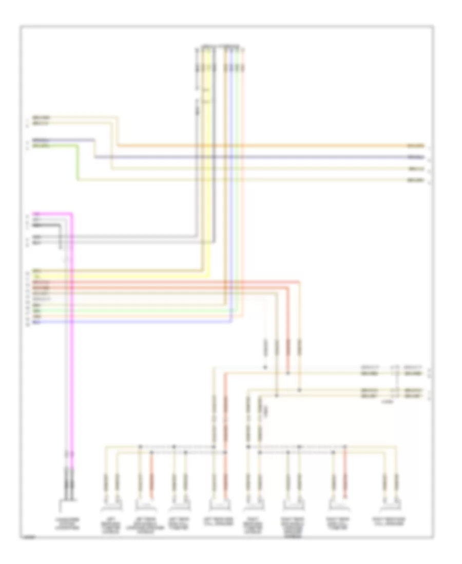
Automatic A/C Wiring Diagram (2 of 4) for Mercedes-Benz Sprinter 2014 2500
List of elements for Automatic A/C Wiring Diagram (2 of 4) for Mercedes-Benz Sprinter 2014 2500:
- A/c 2 additional fan
- A/c mono fan resistor
- Ac 1 additional fan
- Additional fan relay
- Duo fan
- Fuse 150a
- Fuse 80a
- Fuse box
- Hot at all times
- Mono fan
- Red
- X64/13
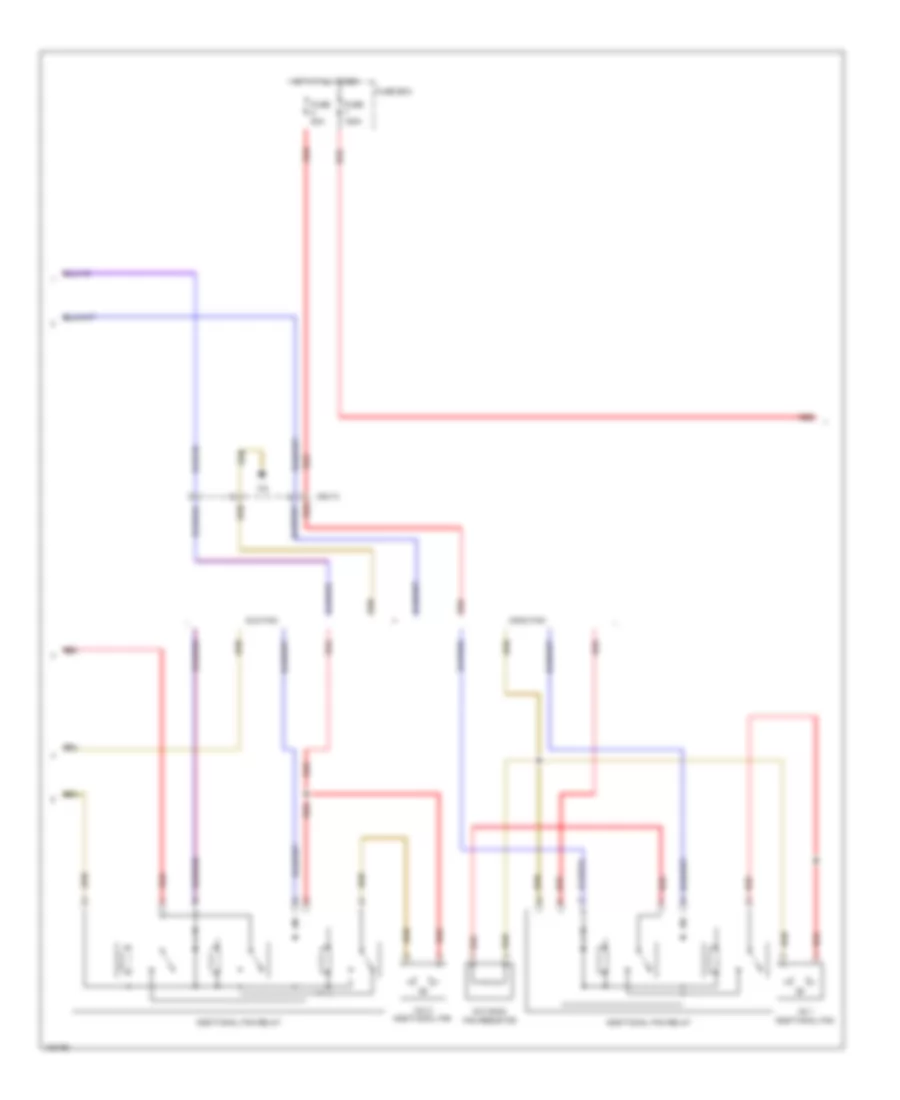
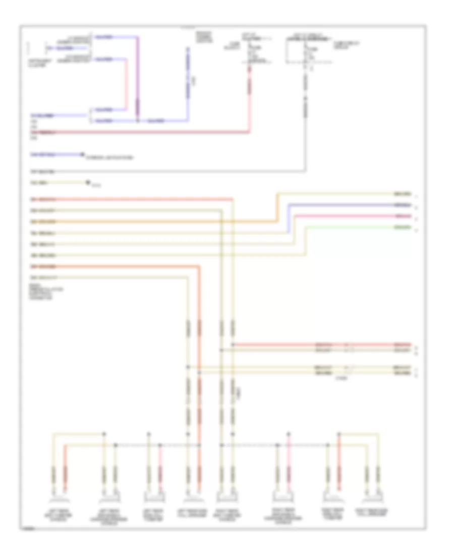
Automatic A/C Wiring Diagram (3 of 4) for Mercedes-Benz Sprinter 2014 2500
List of elements for Automatic A/C Wiring Diagram (3 of 4) for Mercedes-Benz Sprinter 2014 2500:
- 12a
- 18a
- 18b
- 50a
- A/c fuse
- Blower motor
- Blower regulator
- Evaporator temperature sensor
- Fresh air/air recirculation flap actuator motor
- Fuse 30a
- Fuse 7.5a
- Fuse block 2
- Hot at all times
- Nca
- Pnk
- Red
- Red/pnk
- Roof a/c 1 additional fan
- Roof a/c 2 additional fan
- Roof additional fan relay
- W1/3
- W38
- X31
- X31/9
- X53/8
- X64/14
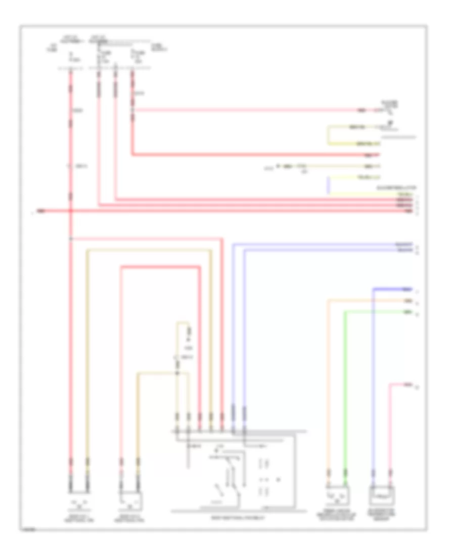
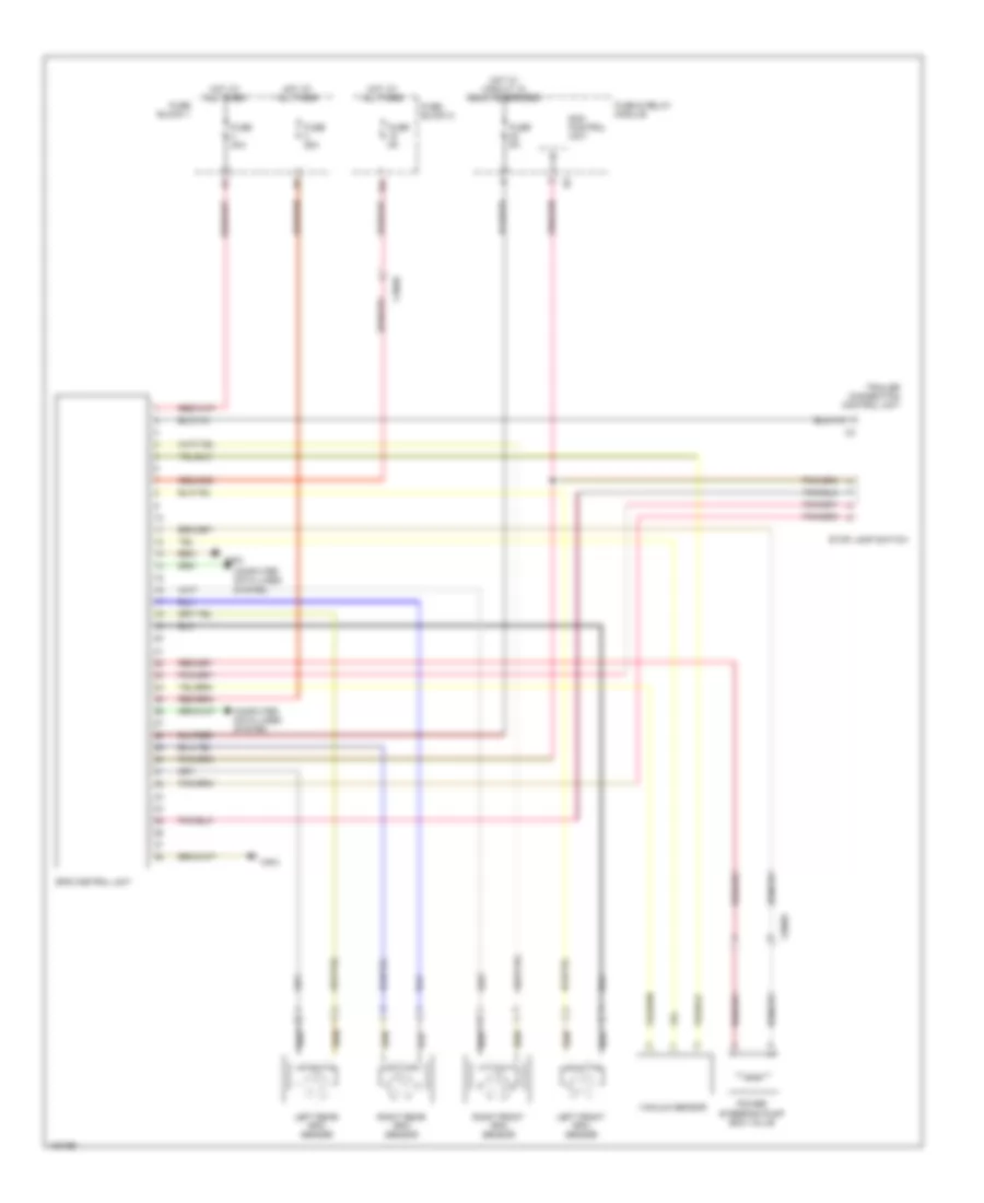
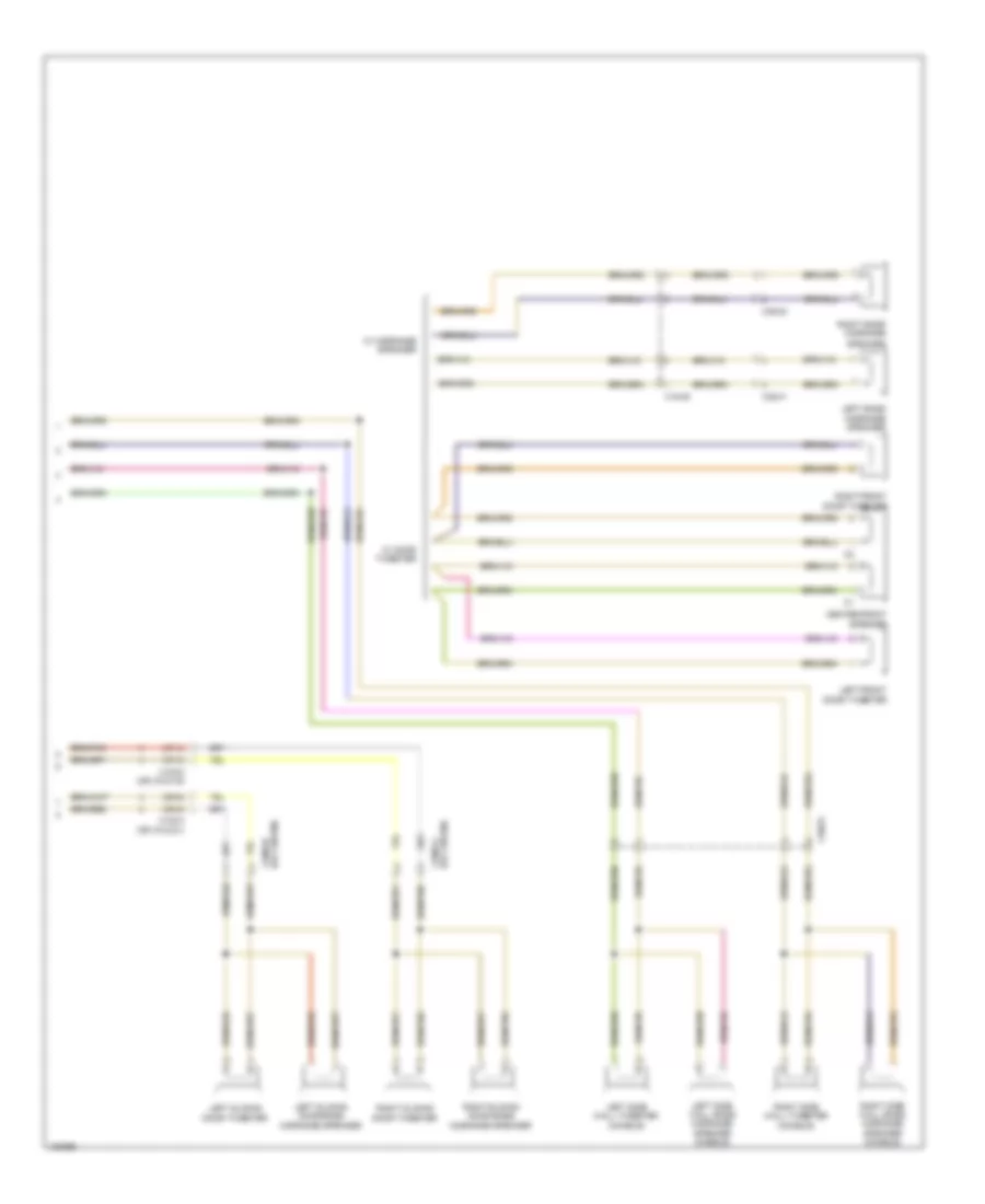
Automatic A/C Wiring Diagram (4 of 4) for Mercedes-Benz Sprinter 2014 2500
List of elements for Automatic A/C Wiring Diagram (4 of 4) for Mercedes-Benz Sprinter 2014 2500:
- 2nd refrigerant compressor
- Ac control & operating unit
- Actuator motor
- Air distribution
- Blending air flap actuator motor
- Cdi control unit
- Computer data lines system
- Coolant temperature sensor
- Electric ptc heater booster
- Pnk
- Red
- Red/pnk
- Roof refrigerant pressure sensor
- W10
- X18/55
- X18/75
- X26/61 (or x26/65)
- X64/14
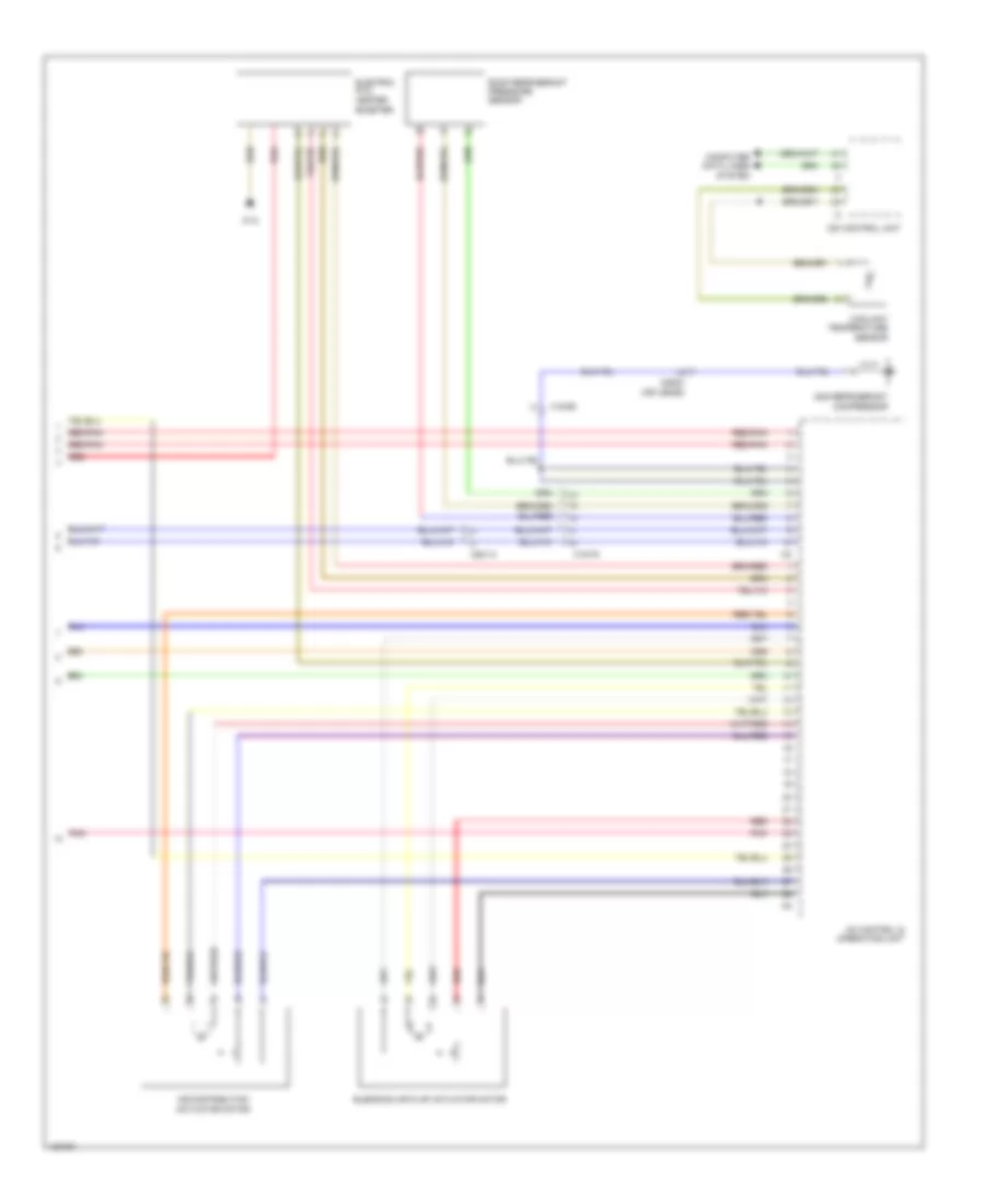
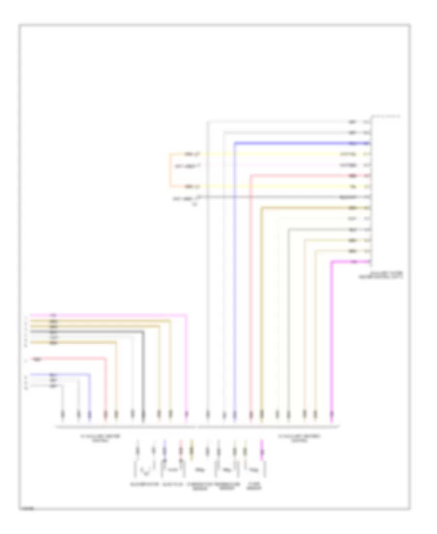
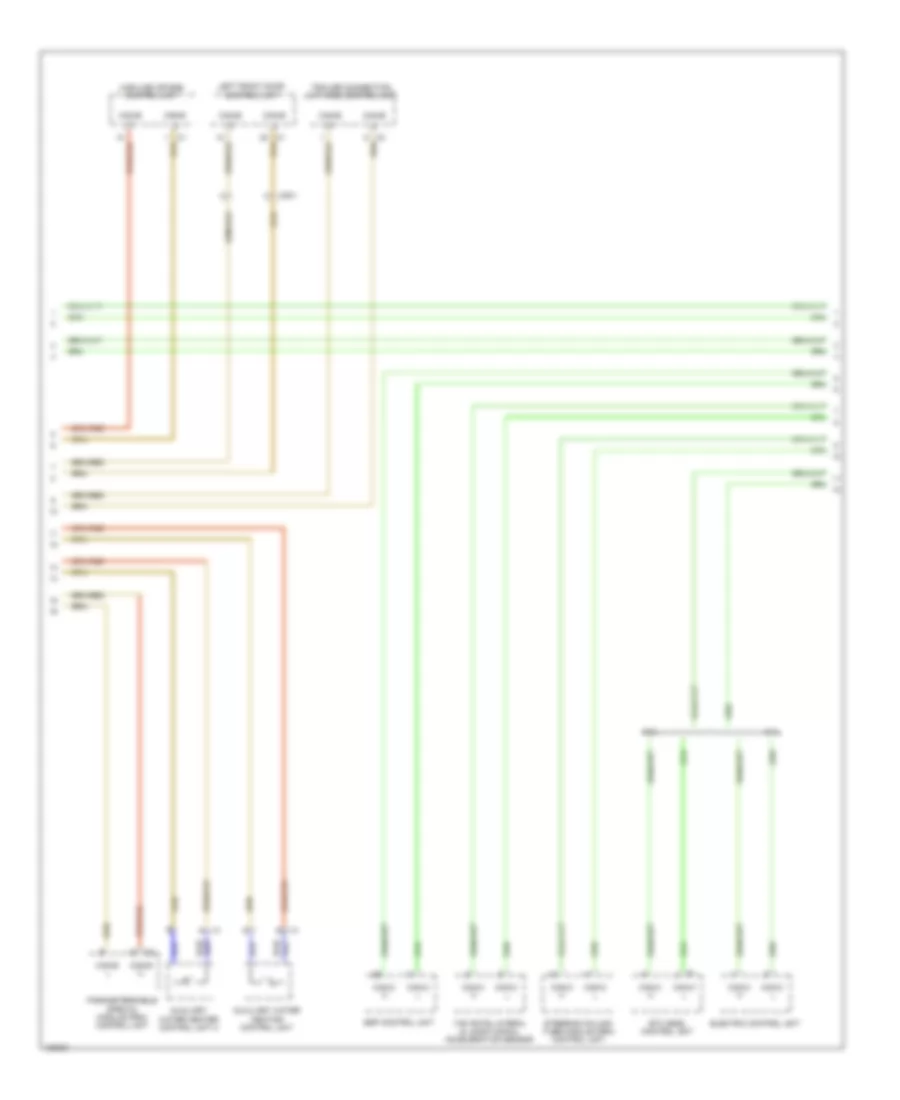
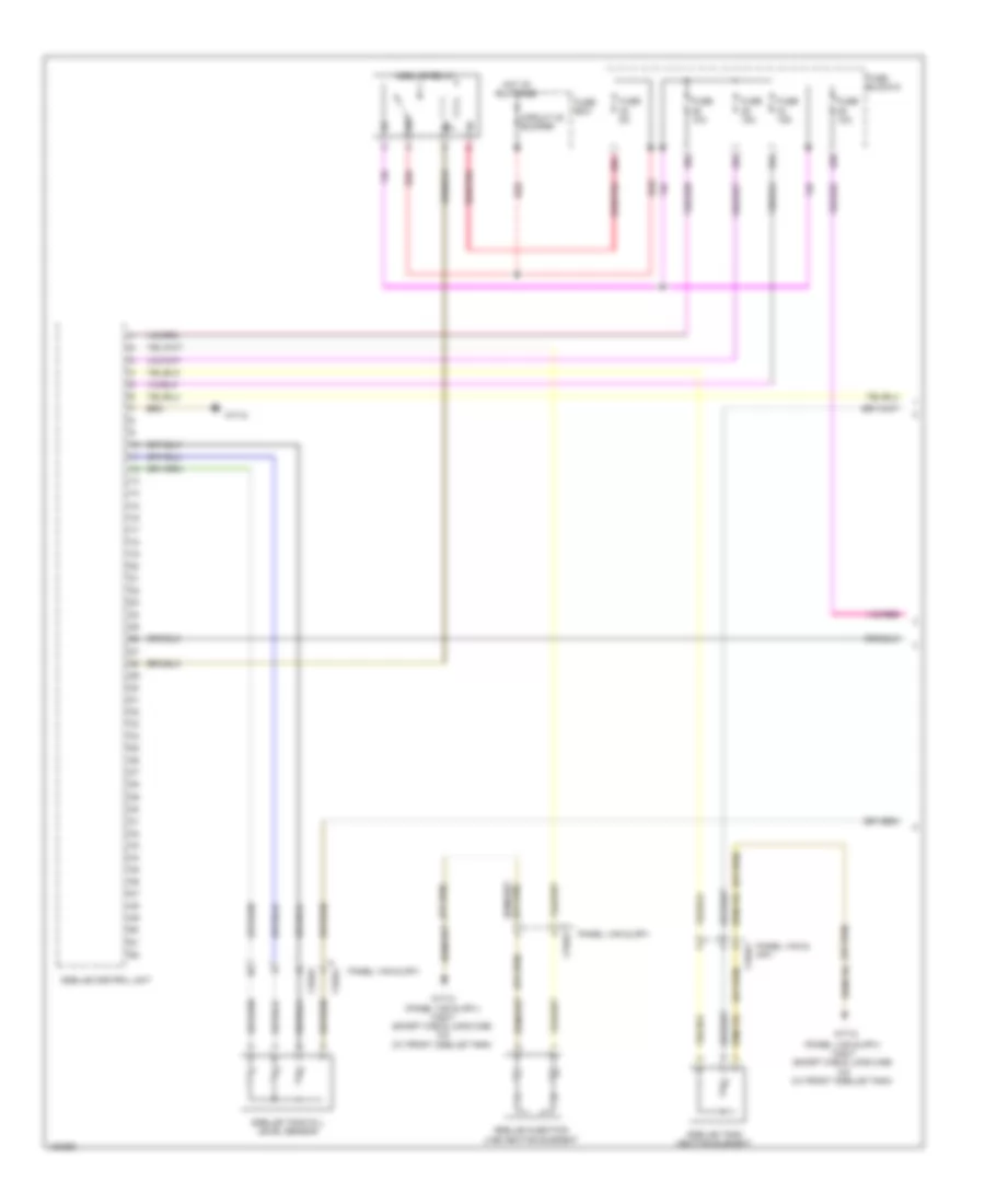
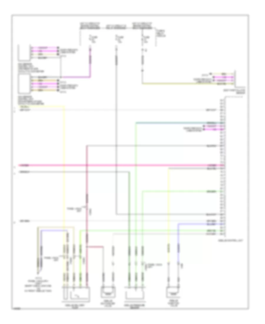
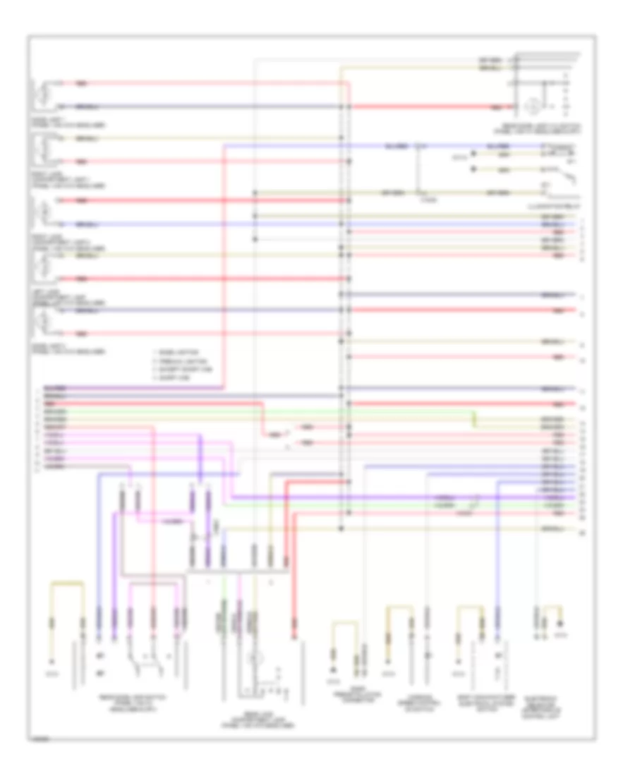
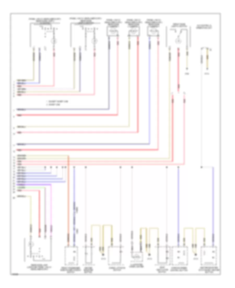
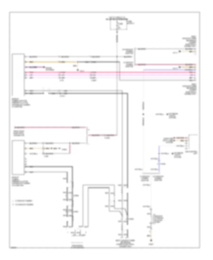
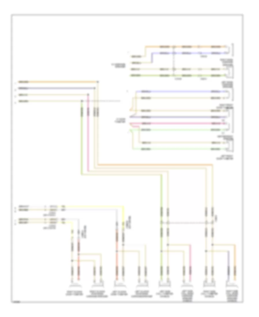
Automatic Heater Control Unit Wiring Diagram for Mercedes-Benz Sprinter 2014 2500
List of elements for Automatic Heater Control Unit Wiring Diagram for Mercedes-Benz Sprinter 2014 2500:
- (not used)
- 12a
- 16a
- 31b
- Ac control & operating unit
- Blower motor
- Blower motor series resistor group
- Blower regulator rear heater
- Blower stage 1
- Cdi control unit
- Circulation pump
- Computer data lines system
- Coolant temperature sensor
- Electric ptc heater booster
- Fan relay
- Fresh air/air recirculation flap actuator motor
- Fuse & relay module
- Fuse 10a
- Fuse 150a
- Fuse 30a
- Fuse 5a
- Fuse block 2
- Fuse block 6
- Fuse box
- Hot at all times
- Hot w/ circuit 15 relay energized
- Interior lights system
- Rear heater
- Rear heater water valve potentiometer
- Rear heater/air conditioner air recirculation unit
- Red
- W1/3
- W10
- W71/2
- W9/7
- X18/55
- X18/77
- X18/78
- X31/10
- X31/12
- X31/9
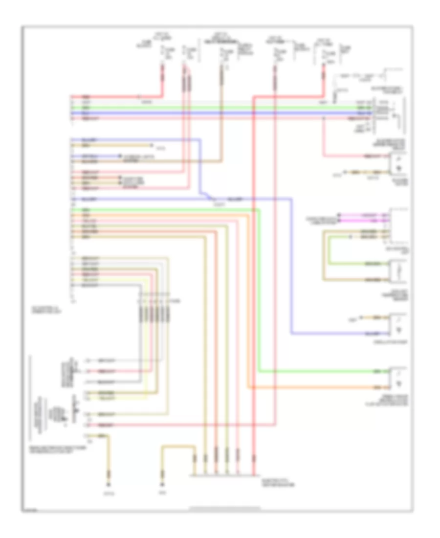
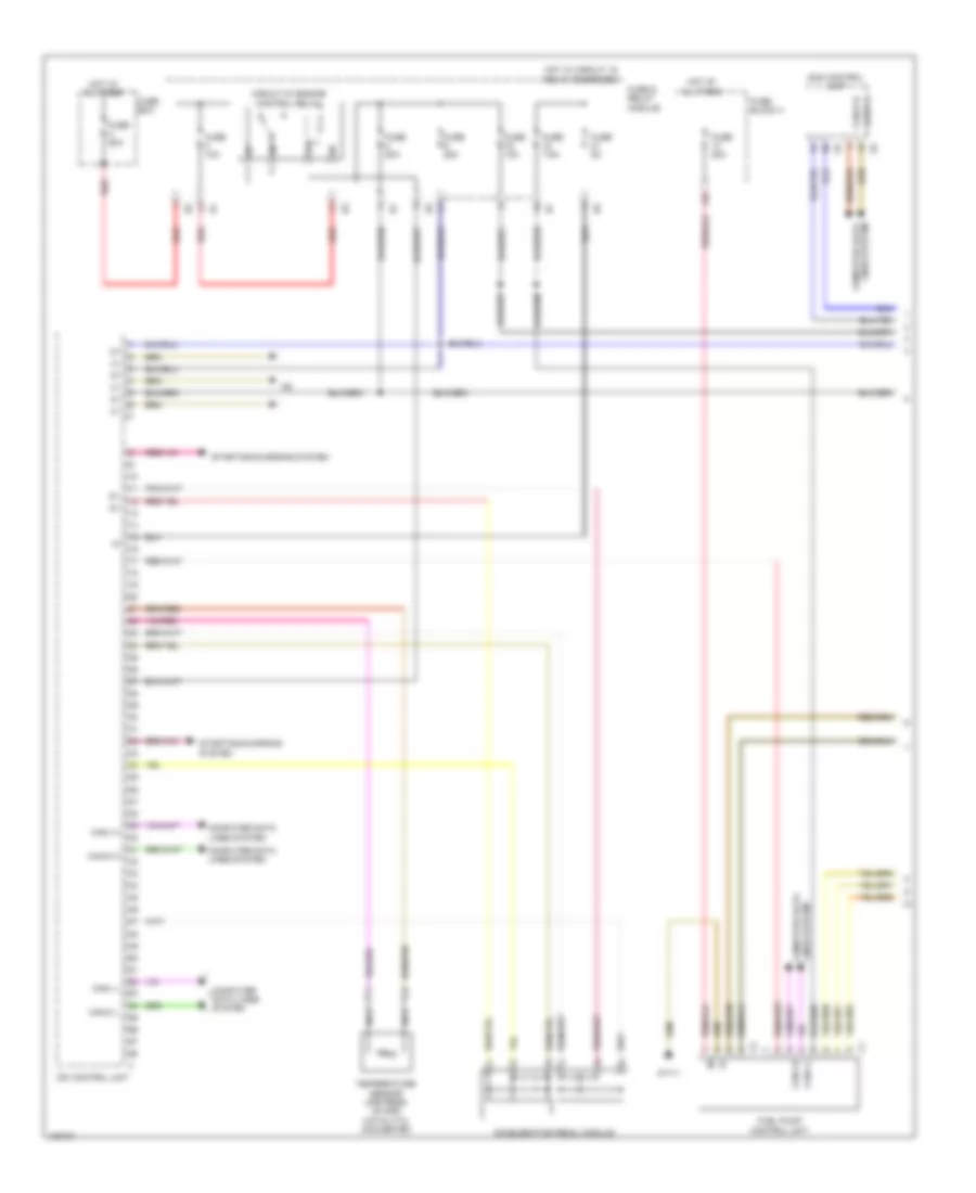
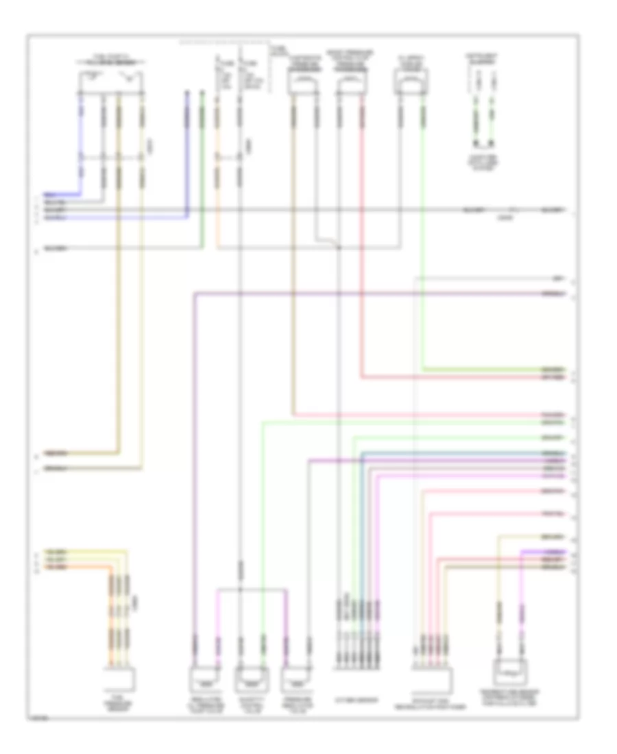
Auxiliary Heater Wiring Diagram (1 of 2) for Mercedes-Benz Sprinter 2014 2500
List of elements for Auxiliary Heater Wiring Diagram (1 of 2) for Mercedes-Benz Sprinter 2014 2500:
- (if equipped) blower stage 1 fan relay
- 12b
- 13a
- 26a
- 27b
- Aac [kla] control & operating unit
- Auxiliary water heater control unit
- Auxiliary water heater control unit 2
- Blower motor series resistor group
- Booster
- Circulation pump
- Computer data lines system
- Fuse 25a
- Fuse 30a
- Fuse 7.5a
- Fuse block 2
- Fuse block 5
- Heater booster button
- Heater booster/stationary heater button
- Hot at all times
- Interior lights system
- Metering pump
- Nca
- Outside temperature sensor
- Red
- Sam control unit
- Stationary heater telestart receiver
- Stationary heater telestart receiver antenna
- W/ heater
- W/o heater
- W1/3
- W71/2
- W9/7
- X18/56
- X18/78
- X31/10
Auxiliary Heater Wiring Diagram (2 of 2) for Mercedes-Benz Sprinter 2014 2500
List of elements for Auxiliary Heater Wiring Diagram (2 of 2) for Mercedes-Benz Sprinter 2014 2500:
- (not used)
- Auxiliary water heater control unit 2
- Blower motor
- Control
- Flame
- Glow plug
- Overheating
- Red
- Sensor
- Temperature
- W/ auxiliary heater
- W/ auxiliary heater 2
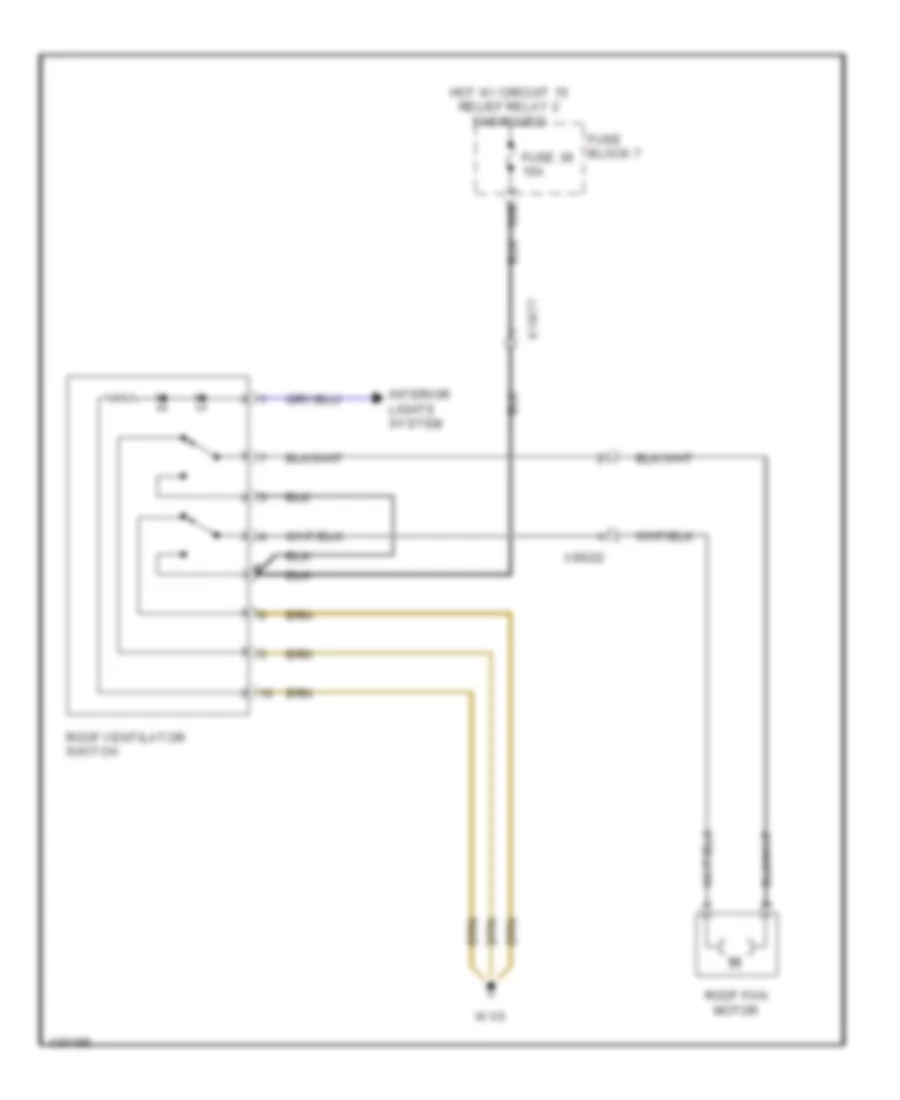
Roof Ventilator Wiring Diagram for Mercedes-Benz Sprinter 2014 2500
List of elements for Roof Ventilator Wiring Diagram for Mercedes-Benz Sprinter 2014 2500:
- 39b
- Fuse 39 15a
- Fuse block 7
- Hot w/ circuit 15 relief relay 2 energized
- Interior lights system
- Roof fan motor
- Roof ventilator switch
- W1/3
- X18/77
- X85/22
ANTI-LOCK BRAKES
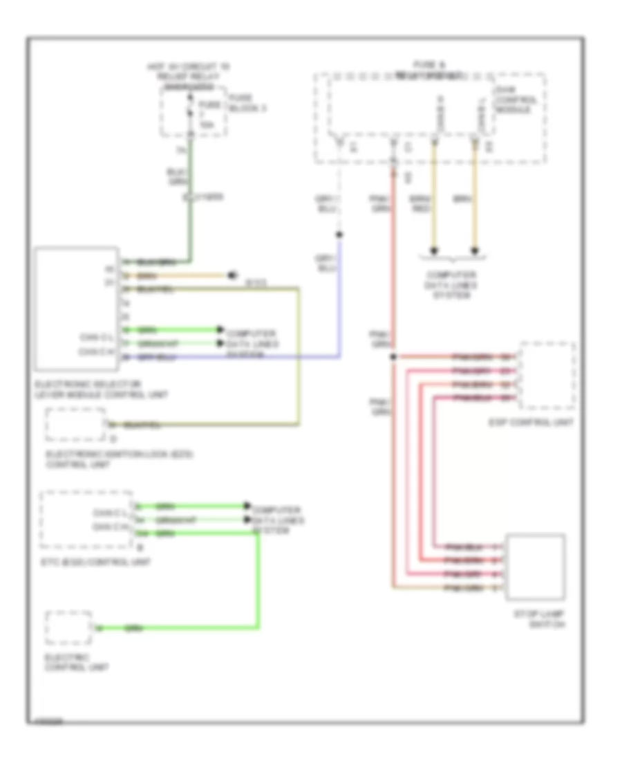
Anti-lock Brakes Wiring Diagram for Mercedes-Benz Sprinter 2014 2500
List of elements for Anti-lock Brakes Wiring Diagram for Mercedes-Benz Sprinter 2014 2500:
- 15a
- Computer data lines system
- Eps control unit
- Fuse & relay module
- Fuse 25a
- Fuse 40a
- Fuse 5a
- Fuse block 1
- Fuse block 2
- Hot at all times
- Hot w/ circuit 15 relay energized
- Left front rpm sensor
- Left rear rpm sensor
- Power steering pump eco valve
- Right front rpm sensor
- Right rear rpm sensor
- Sam control unit
- Stop lamp switch
- Trailer connection control unit
- Vacuum sensor
- W9/3
- X18/56
- X26/65
ANTI-THEFT
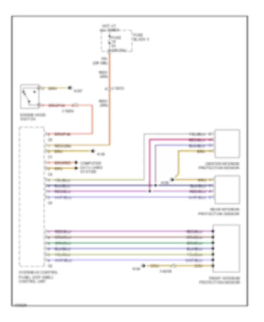
Anti-theft Wiring Diagram for Mercedes-Benz Sprinter 2014 2500
List of elements for Anti-theft Wiring Diagram for Mercedes-Benz Sprinter 2014 2500:
- 19a (or 19b)
- Center interior protection sensor
- Computer data lines system
- Engine hood switch
- Front interior protection sensor
- Fuse 5a (or 25a)
- Fuse block 5
- Hot at all times
- Overhead control
- Panel (ocp (dbe)) control unit
- Rear interior protection sensor
- W38
- W9/7
- X18/53
- X18/54
- X42/28
BODY CONTROL MODULES
Overhead Control Panel Wiring Diagram for Mercedes-Benz Sprinter 2014 2500
List of elements for Overhead Control Panel Wiring Diagram for Mercedes-Benz Sprinter 2014 2500:
- 19a (or 19b)
- Anti-theft system
- Can-b h
- Can-b l
- Computer data lines system
- Fuse 5a (or 25a)
- Fuse block 5
- Horns system
- Hot at all times
- Overhead control panel (ocp (dbe)) control unit
- Power tops system
- Sam control circuit
- W38
- Wiper/washer & headlights systems
- X18/53
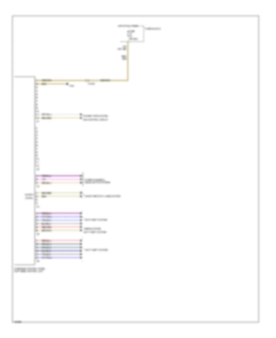
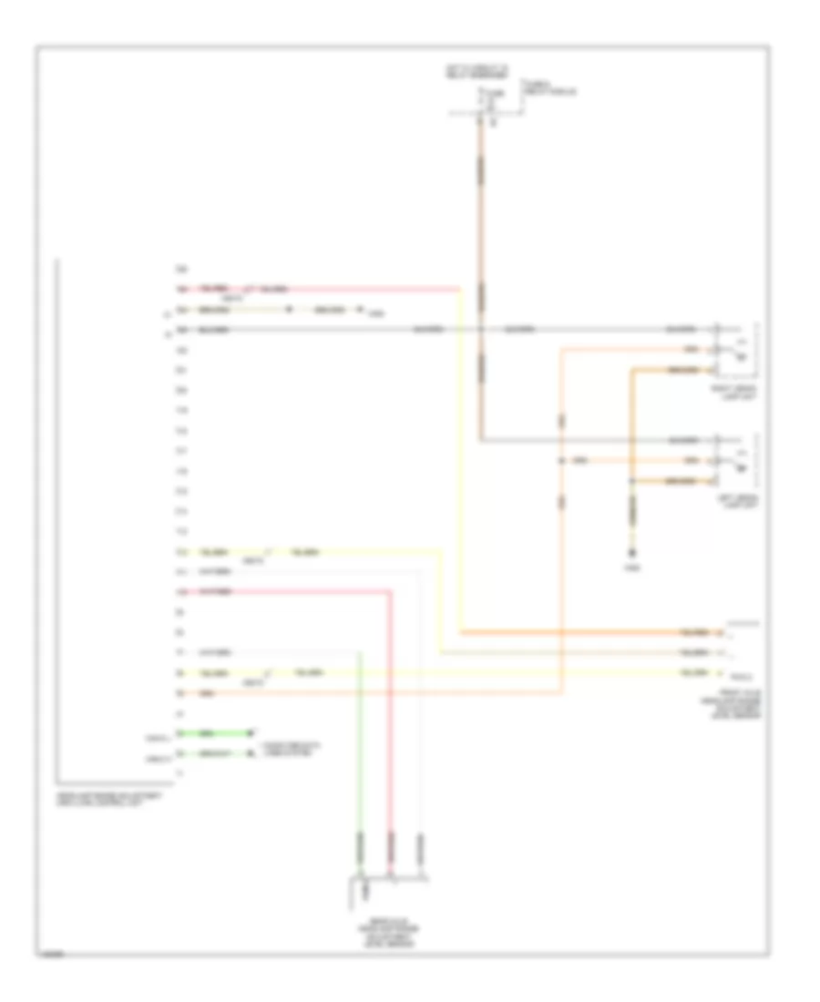
Programmable Special Module Wiring Diagram for Mercedes-Benz Sprinter 2014 2500
List of elements for Programmable Special Module Wiring Diagram for Mercedes-Benz Sprinter 2014 2500:
- Can-b h
- Can-b l
- Computer data lines system
- Fuse 25a
- Fuse 7.5a
- Fuse block
- Fuse block 3
- Hot at all times
- Hot w/ circuit 15 relief relay energized
- Interior lights system
- Parameterizable special module (psm) control unit
- Pnk
- Trunk, tailgate, fuel doors system
- W/ working speed control on switch
- W/o working speed control on switch
- W1/3
- W71/1
- Working speed control button
- Working speed control on switch
- X18/55
- X18/56
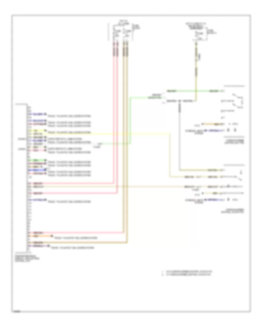
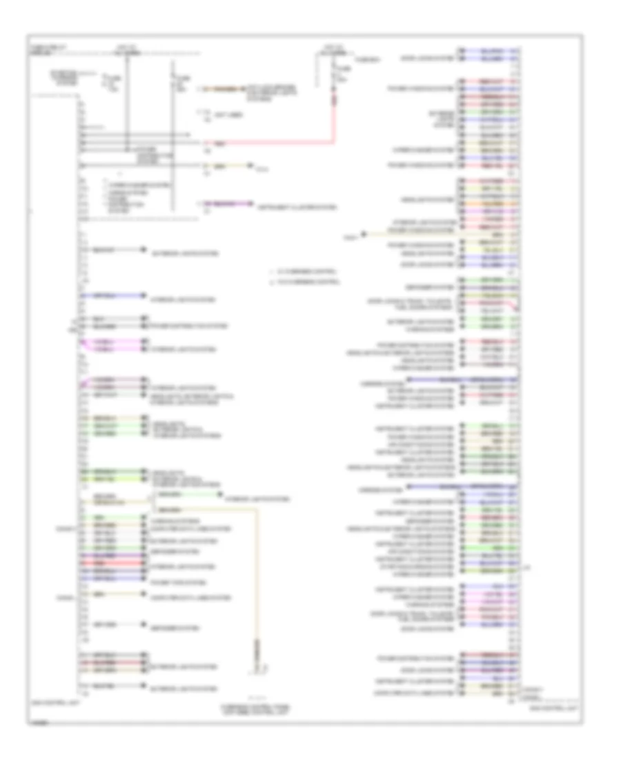
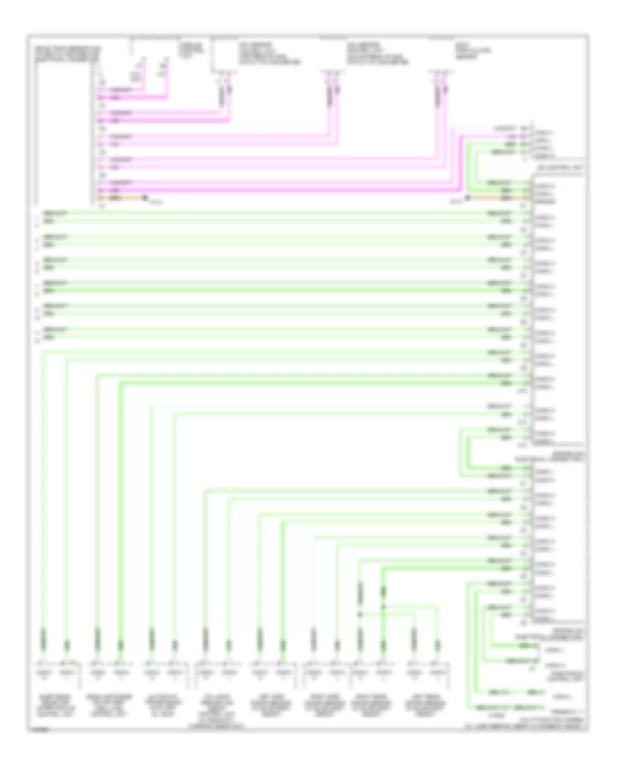
SAM Control Wiring Diagram for Mercedes-Benz Sprinter 2014 2500
List of elements for SAM Control Wiring Diagram for Mercedes-Benz Sprinter 2014 2500:
- (not used)
- 15r
- Air conditioning system
- Anti-lock brakes & exterior lights systems
- Can-b h
- Can-b l
- Computer data lines system
- Defogger system
- Door locks & trunk, tailgate, fuel doors systems
- Door locks system
- Exterior lights system
- Fuse & relay module
- Fuse 25a
- Fuse 7.5a
- Fuse 80a
- Fuse box
- Headlights & exterior lights systems
- Headlights system
- Headlights, exterior lights & interior lights systems
- Horns system
- Hot at all times
- Instrument cluster system
- Interior lights system
- Lin
- Mirrors system
- Overhead control panel (ocp (dbe)) control unit
- Power distribution system
- Power tops system
- Power windows system
- Red
- Sam control unit
- Starting/ charging system
- Starting/charging system
- W/ overhead control
- W/o overhead control
- W1/4
- W43/1
- Warning systems
- Wiper/washer system
COMPUTER DATA LINES
Computer Data Lines Wiring Diagram (1 of 3) for Mercedes-Benz Sprinter 2014 2500
List of elements for Computer Data Lines Wiring Diagram (1 of 3) for Mercedes-Benz Sprinter 2014 2500:
- -b l
- 2a red
- Ac control & operating unit
- Audio 10
- Audio 15
- Automatic a/c
- Automatic heater
- C11
- Can
- Can - a h
- Can - a l
- Can - b h
- Can - b l
- Can -a h
- Can -a l
- Can -b
- Can-b h
- Can-b l
- Can-c h
- Can-c l
- Cardle for becker map pilot
- Diagnostic connector
- Electric ptc heater booster (automatic heater)
- Electronic ignition lock (ezs) control unit
- Fuse & relay module
- Fuse 14 5a
- Fuse 2 10a
- Fuse block 1
- Hot at all times
- Hot w/ circuit 15 starter relay energized
- Instrument cluster
- Interior can electrical connector (x30/24)
- Interior can electrical connector (x30/25)
- Interior can electrical connector (x30/26)
- Overhead control panel (ocp (dbe)) control unit
- Radio/radio w/ navigation
- Red
- Sam control unit
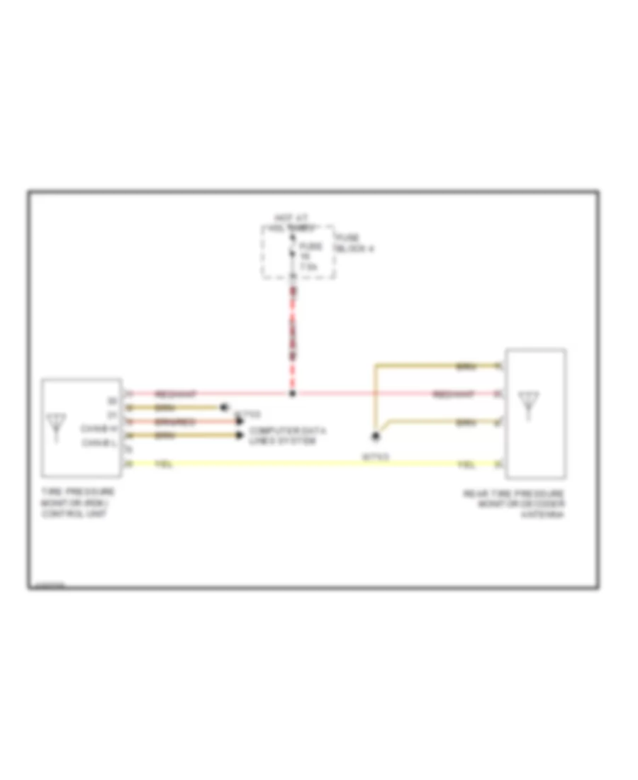
- Tire pressure monitor (rdk) control unit
- Upper control panel (ucp (obf)) control unit
- W43/1
- X18/56
Computer Data Lines Wiring Diagram (2 of 3) for Mercedes-Benz Sprinter 2014 2500
List of elements for Computer Data Lines Wiring Diagram (2 of 3) for Mercedes-Benz Sprinter 2014 2500:
- 2.1l
- 3.0l
- Auxiliary water heater control unit 2
- Auxiliary water heating control unit
- B l
- Can-b h
- Can-b l
- Can-c h
- Can-c l
- Control unit
- Electric control unit
- Esp control unit
- Etc (egs) control unit
- Highline air bag control unit
- Left front door
- Parameterizable special module (psm) control unit
- Steering column tube module (mrm) control unit
- Trailer connection unit (aag) control unit
- X35/1
- Yaw rate lateral & longitudinal acceleration sensor
Computer Data Lines Wiring Diagram (3 of 3) for Mercedes-Benz Sprinter 2014 2500
List of elements for Computer Data Lines Wiring Diagram (3 of 3) for Mercedes-Benz Sprinter 2014 2500:
- Automatic transmission auxiliary oil pump
- C10
- C12
- C13
- Can-c h
- Can-c l
- Can-i h
- Can-i l
- Cdi control unit
- Collision prevention assist control unit (w/ proximity warning assistant)
- Drive train sensor can potential distributor electrical connector
- Electronic selector lever module control unit
- Engine can electrical connector 2
- Engine can electrical connector 3
- Ground
- Headlamp range adjustment (hra (lwr)) control unit
- Left rear radar sensor (w/ blind spot assist)
- Left side radar sensor (w/ blind spot assist)
- Multi-function camera (w/ lane keeping assist & highbeam assist)
- Nox sensor control unit downstream of scr catalytic converter
- Nox sensor control unit upstream of scr catalytic converter
- Parktronic control unit
- Right rear radar sensor (w/ blind spot assist)
- Right side radar sensor (w/ blind spot assist)
- Soot particulate sensor
- W1/4
- X18/82
DEFOGGERS
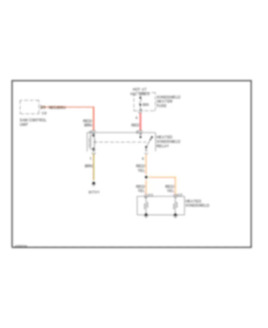
Heated Windshield Wiring Diagram for Mercedes-Benz Sprinter 2014 2500
List of elements for Heated Windshield Wiring Diagram for Mercedes-Benz Sprinter 2014 2500:
- 80a
- Heated windshield
- Heated windshield relay
- Hot at all times
- Red
- Sam control unit
- W71/1
- Windshield heater fuse
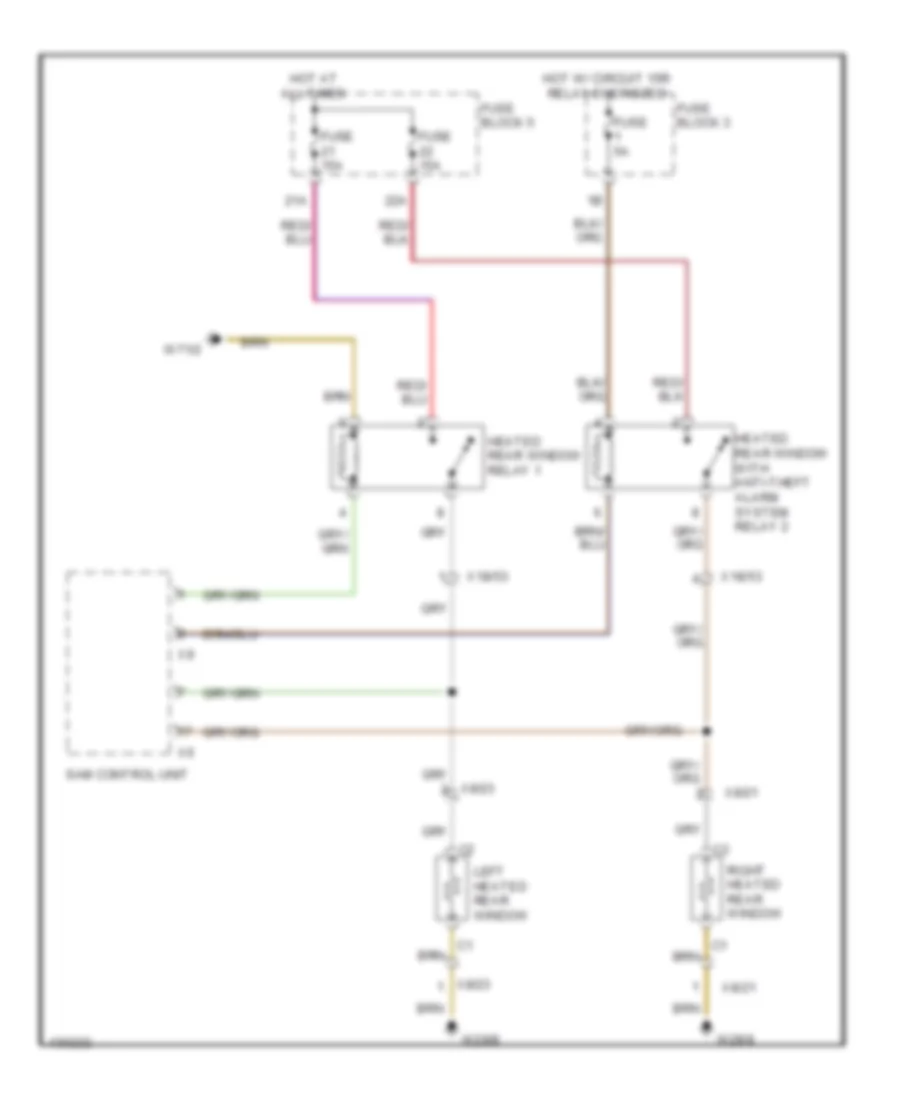
Rear Defogger Wiring Diagram, with Anti-theft Alarm for Mercedes-Benz Sprinter 2014 2500
List of elements for Rear Defogger Wiring Diagram, with Anti-theft Alarm for Mercedes-Benz Sprinter 2014 2500:
- 21a
- 22a
- Fuse 15a
- Fuse 5a
- Fuse block 3
- Fuse block 5
- Heated rear window relay 1
- Heated rear window with anti-theft alarm system relay 2
- Hot at all times
- Hot w/ circuit 15r relay energized
- Left heated rear window
- Right heated rear window
- Sam control unit
- W29/8
- W71/2
- X18/53
- X8/21
- X8/23
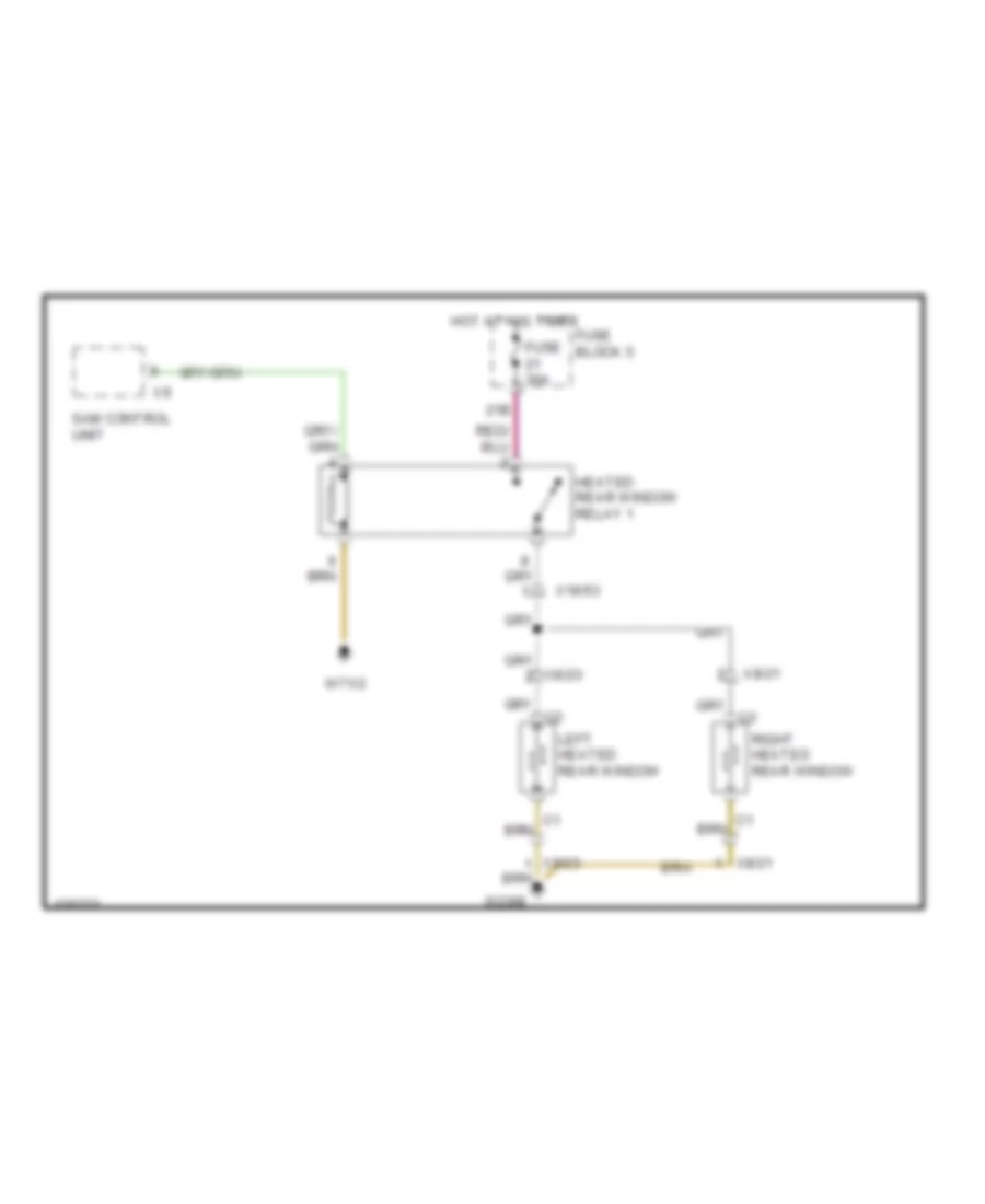
Rear Defogger Wiring Diagram, without Anti-theft Alarm for Mercedes-Benz Sprinter 2014 2500
List of elements for Rear Defogger Wiring Diagram, without Anti-theft Alarm for Mercedes-Benz Sprinter 2014 2500:
- 21b
- Fuse 30a
- Fuse block 5
- Heated rear window relay 1
- Hot at all times
- Left heated rear window
- Right heated rear window
- Sam control unit
- W29/8
- W71/2
- X18/53
- X8/21
- X8/23
ENGINE ACCESSORIES
2.1L
2.1L, After Treatment Wiring Diagram (1 of 2) for Mercedes-Benz Sprinter 2014 2500
List of elements for 2.1L, After Treatment Wiring Diagram (1 of 2) for Mercedes-Benz Sprinter 2014 2500:
- Computer data lines system
- Fuse & relay module
- Fuse 10a
- Hot w/ circuit 15 relay energized
- W71/2
2.1L, After Treatment Wiring Diagram (2 of 2) for Mercedes-Benz Sprinter 2014 2500
List of elements for 2.1L, After Treatment Wiring Diagram (2 of 2) for Mercedes-Benz Sprinter 2014 2500:
- 32b
- 34b
- 35b
- 36a
- 36b
- Circuit 30 jumper
- Computer data lines system
- Fuse & relay module
- Fuse 10a
- Fuse 15a
- Fuse 20a
- Fuse 25a
- Fuse 5a
- Fuse block 6
- Fuse box
- Hot at all times
- Hot w/ circuit 87 engine control relay energized
- Nox sensor control unit downstream of scr catalytic converter
- Nox sensor control unit upstream of scr catalytic converter
- Red
- Soot particulate sensor
- W71/3
- X196
3.0L
3.0L, After Treatment Wiring Diagram (1 of 2) for Mercedes-Benz Sprinter 2014 2500
List of elements for 3.0L, After Treatment Wiring Diagram (1 of 2) for Mercedes-Benz Sprinter 2014 2500:
- 29b
- 32b
- 34a
- 35a
- 36a
- Circuit 30 bumper
- Fuse 10a
- Fuse 15a
- Fuse 5a
- Fuse block 6
- Fuse box
- Hot at all times
- Panel van & mpv
- Red
- Red/pnk
- W71/2
- X194/3
- X194/4
3.0L, After Treatment Wiring Diagram (2 of 2) for Mercedes-Benz Sprinter 2014 2500
List of elements for 3.0L, After Treatment Wiring Diagram (2 of 2) for Mercedes-Benz Sprinter 2014 2500:
- Computer data lines system
- Fuse & relay module
- Fuse 10a
- Hot w/ circuit 15 relay energized
- Hot w/ circuit 87 engine control relay energized
- Nox sensor control unit downstream of scr catalytic converter
- Nox sensor control unit upstream of scr catalytic converter
- Panel van & mpv
- Soot particulate sensor
- W71/2
- W71/3
- X194/3
- X194/4
- X196
ENGINE PERFORMANCE
2.1L
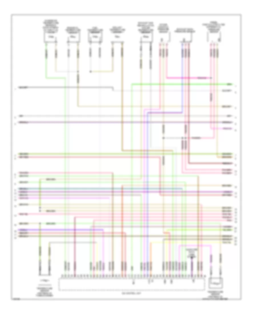
2.1L, Engine Performance Wiring Diagram (1 of 5) for Mercedes-Benz Sprinter 2014 2500
List of elements for 2.1L, Engine Performance Wiring Diagram (1 of 5) for Mercedes-Benz Sprinter 2014 2500:
- 13a
- Accelerator pedal module
- Can-b h
- Can-b l
- Can-c h
- Can-c l
- Can-i h
- Can-i l
- Cdi control unit
- Circuit 87 engine control relay
- Computer data lines system
- Fuel pump control unit
- Fuse & relay module
- Fuse 10a
- Fuse 20a
- Fuse 25a
- Fuse 5a
- Fuse 7.5a
- Fuse 80a
- Fuse block 4
- Fuse box
- Hot at all times
- Hot w/ circuit 15 relay energized
- Lines system computer data
- Nca
- Red
- Sam control unit
- Starting/charging system
- Temperature sensor upstream of scr catalytic converter
- W71/1
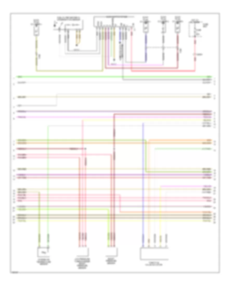
2.1L, Engine Performance Wiring Diagram (2 of 5) for Mercedes-Benz Sprinter 2014 2500
List of elements for 2.1L, Engine Performance Wiring Diagram (2 of 5) for Mercedes-Benz Sprinter 2014 2500:
- (not used)
- Boost pressure control flap pressure transducer
- Can-c h
- Can-c l
- Computer data lines system
- Exhaust gas recirculation positioner
- Fuel pressure sensor
- Fuel pump w/ fill level sensor
- Fuse 7.5a (or 10a)
- Fuse 7.5a (or 10a) (or 5a)
- Fuse block
- Instrument cluster
- Nca
- Oil spray nozzles valve
- Oxygen sensor
- Pressure regulator valve
- Quantity control valve
- Regulated oil pressure pump valve
- Temperature sensor upstream of diesel particulate filter
- Wastegate pressure transducer
- X25/15
- X26/65
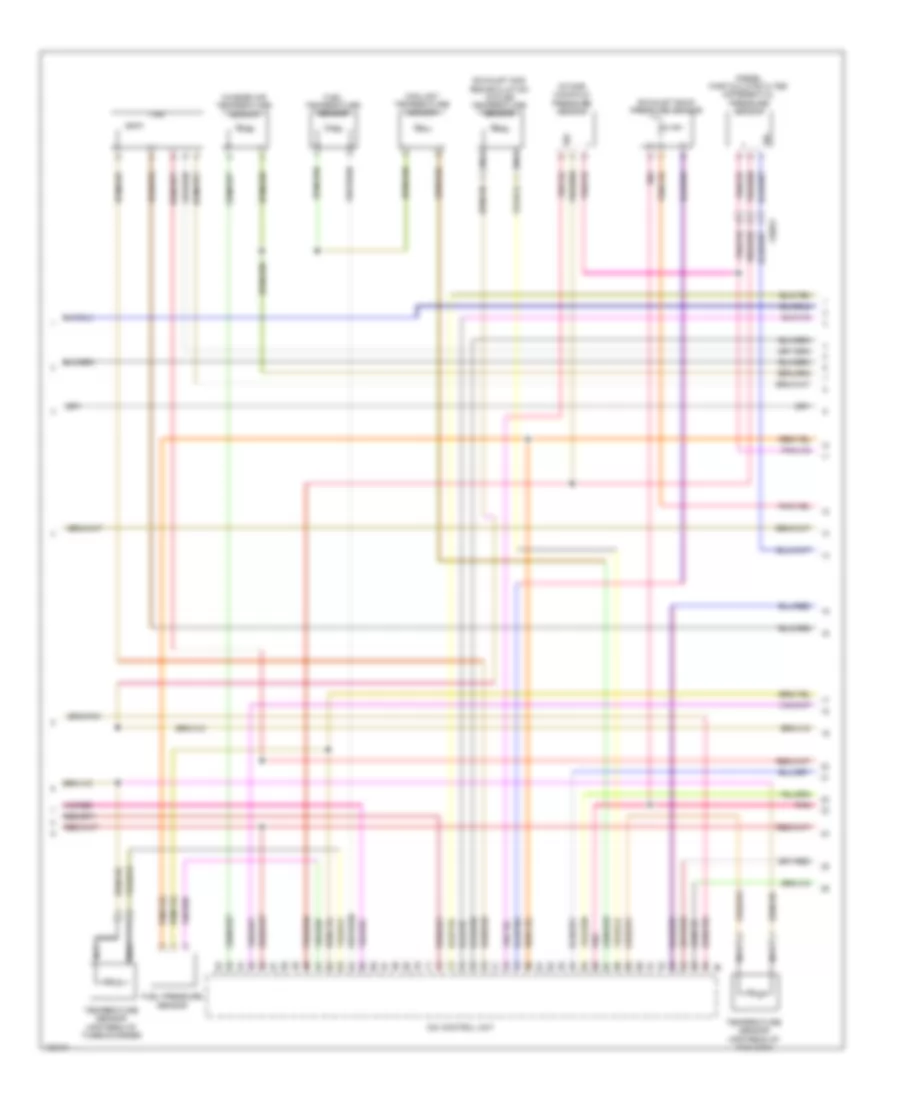
2.1L, Engine Performance Wiring Diagram (3 of 5) for Mercedes-Benz Sprinter 2014 2500
List of elements for 2.1L, Engine Performance Wiring Diagram (3 of 5) for Mercedes-Benz Sprinter 2014 2500:
- Cdi control unit
- Charge air temperature sensor & down stream of throttle valve
- Computer data lines system
- Coolant temperature sensor
- Diesel particulate filter differential pressure sensor
- Engine oil temperature sensor
- Exhaust back pressure sensor
- Exhaust gas recirculation cooler temperature sensor
- F-p3
- Fuel temperature sensor
- Gnd
- Inj l
- Intake manifold pressure sensor
- Lin
- Nca
- Pnk
- Sig
- Temperature sensor upstream of catalytic converter
- Temperature sensor upstream of turbocharger
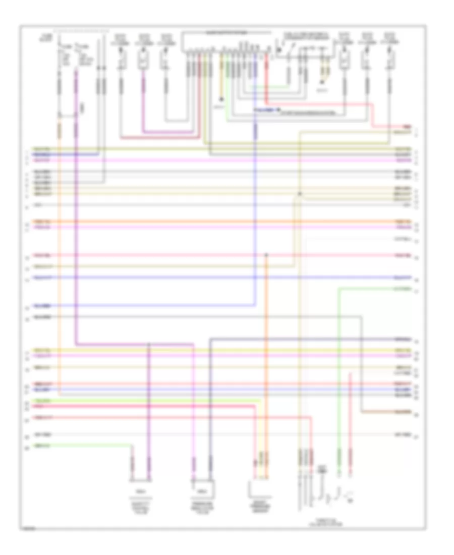
2.1L, Engine Performance Wiring Diagram (4 of 5) for Mercedes-Benz Sprinter 2014 2500
List of elements for 2.1L, Engine Performance Wiring Diagram (4 of 5) for Mercedes-Benz Sprinter 2014 2500:
- Boost pressure sensor
- Charge air temperature sensor
- Computer data lines system
- Fuel filter heater w/ condensation sensor
- Fuse 80a
- Fuse box
- Glow output stage
- Glow plug cylinder 1
- Glow plug cylinder 2
- Glow plug cylinder 3
- Glow plug cylinder 4
- Hot at all times
- Kfh1
- Kfh2
- Lin
- Low-pressure turbocharger boost pressure sensor
- Pnk
- Red
- Sig-wss
- Throttle valve actuator
- W11/1
- X195
- X26/64
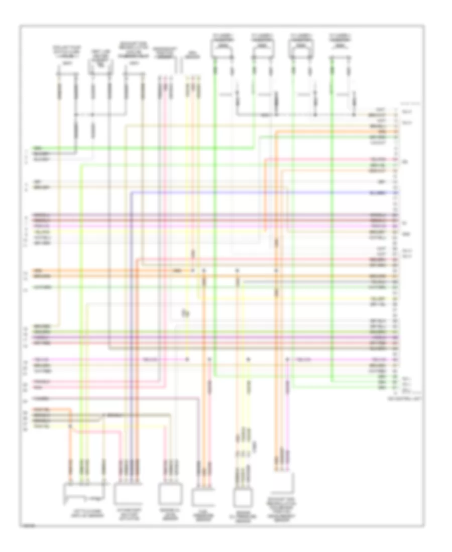
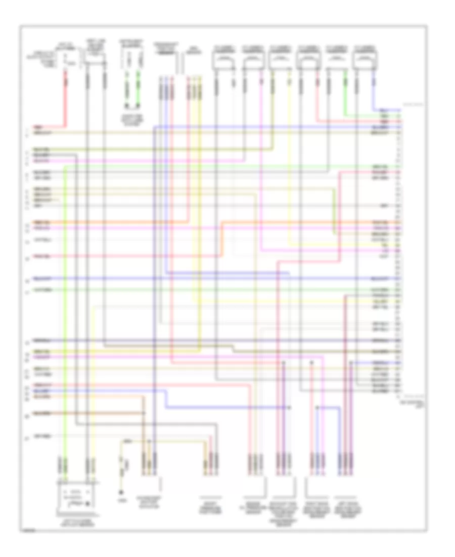
2.1L, Engine Performance Wiring Diagram (5 of 5) for Mercedes-Benz Sprinter 2014 2500
List of elements for 2.1L, Engine Performance Wiring Diagram (5 of 5) for Mercedes-Benz Sprinter 2014 2500:
- Cdi control unit
- Coolant pump switch over valve
- Crankshaft position sensor
- Cylinder 1 injector
- Cylinder 2 injector
- Cylinder 3 injector
- Cylinder 4 injector
- Engine oil level sensor
- Engine oil pressure sensor
- Exhaust gas recirculation cooler end position measurement sensor
- Exhaust gas recirculation cooling solenoid valve
- Fuel pressure sensor
- Gnd
- Hot film mass air flow sensor
- Inj h
- Inj l
- Intake port shutoff actuator
- Nca
- Pnk
- Rpm sensor
- Vent line heater element
- X156/3
3.0L
3.0L, Engine Performance Wiring Diagram (1 of 4) for Mercedes-Benz Sprinter 2014 2500
List of elements for 3.0L, Engine Performance Wiring Diagram (1 of 4) for Mercedes-Benz Sprinter 2014 2500:
- (not used)
- 13b
- Accelerator pedal module
- Cdi control unit
- Circuit 87 engine control relay
- Computer data lines system
- Exhaust gas recirculation cooling solenoid valve
- Exhaust gas recirculation positioner
- Fuel pump diode
- Fuel pump relay
- Fuel pump w/ fill level sensor
- Fuse & relay module
- Fuse 10a
- Fuse 20a
- Fuse 25a
- Fuse 5a
- Fuse 80a
- Fuse block 4
- Fuse box
- Hot at all times
- Hot w/ circuit 15 relay energized
- Nca
- Oxygen sensor
- Red
- Starting/charging system
- Temperature sensor upstream of diesel particulate filter
- Temperature sensor upstream of scr catalytic converter
- W52/7
- W71/1
- W9/6
- X25/15
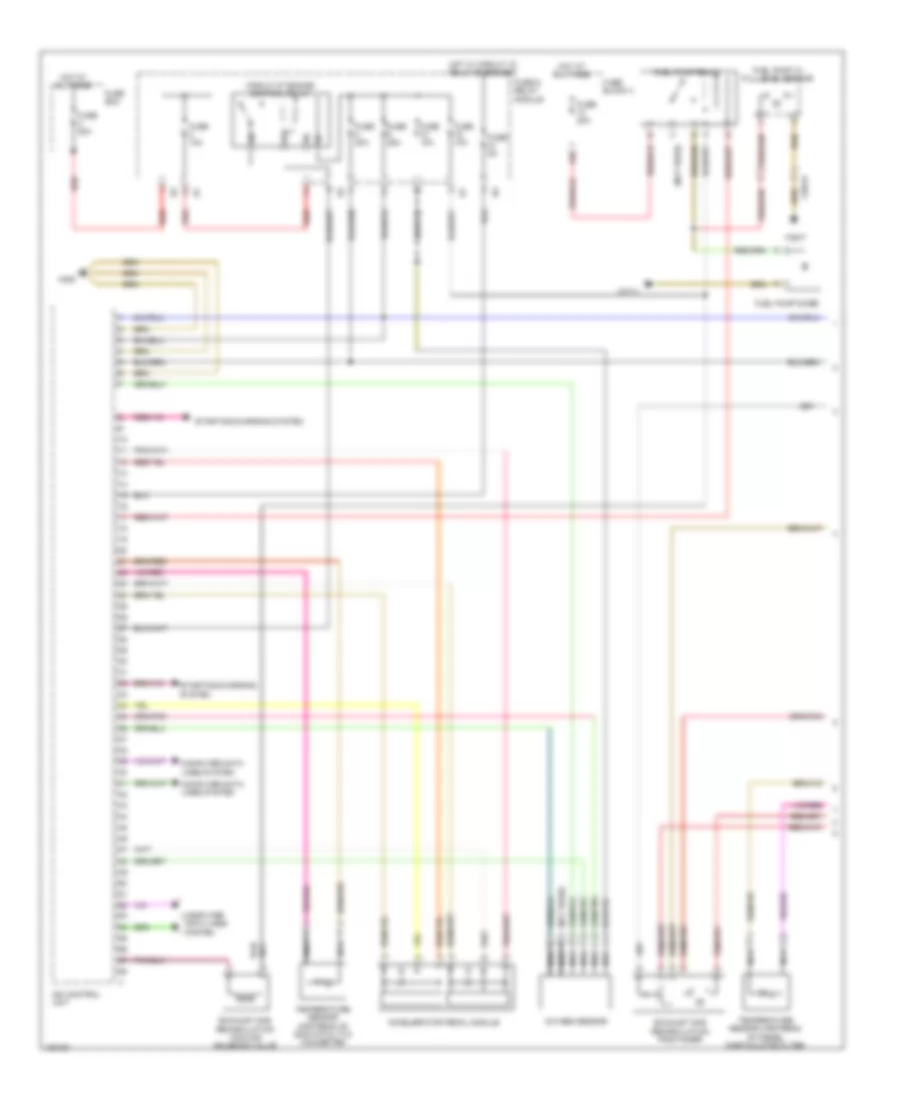
3.0L, Engine Performance Wiring Diagram (2 of 4) for Mercedes-Benz Sprinter 2014 2500
List of elements for 3.0L, Engine Performance Wiring Diagram (2 of 4) for Mercedes-Benz Sprinter 2014 2500:
- Cdi control unit
- Charge air temperature sensor
- Coolant temperature sensor
- Diesel particulate filter differential pressure sensor
- Exhaust back pressure sensor
- Exhaust gas recirculation cooler temperature sensor
- Fan
- Fuel pressure sensor
- Fuel temperature sensor
- Intake manifold pressure sensor
- Nca
- Pnk
- Sig
- Temperature sensor upstream of turbocharger
- Temperature sensor upstream of twc (kat)
- X26/53
3.0L, Engine Performance Wiring Diagram (3 of 4) for Mercedes-Benz Sprinter 2014 2500
List of elements for 3.0L, Engine Performance Wiring Diagram (3 of 4) for Mercedes-Benz Sprinter 2014 2500:
- (not used)
- Boost pressure sensor
- Fuel filter heater w/ condensation sensor
- Fuse 7.5a (or 10a)
- Fuse 7.5a (or 10a) (or 5a)
- Fuse block
- Glow output stage
- Glow plug cylinder
- Kfh1
- Kfh2
- Lin
- Pnk
- Pressure regulator valve
- Quantity control valve
- Red
- Sig
- Starting/charging system
- Throttle valve actuator
- W11/1
- X26/61
3.0L, Engine Performance Wiring Diagram (4 of 4) for Mercedes-Benz Sprinter 2014 2500
List of elements for 3.0L, Engine Performance Wiring Diagram (4 of 4) for Mercedes-Benz Sprinter 2014 2500:
- 100a
- Boost pressure positioner
- Can-c h
- Can-c l
- Cdi control unit
- Circuit 30 glow output stage fuse
- Computer data lines system
- Crankshaft position sensor
- Cylinder 1 injector
- Cylinder 2 injector
- Cylinder 3 injector
- Cylinder 4 injector
- Cylinder 5 injector
- Cylinder 6 injector
- Engine oil pressure sensor
- Exhaust gas recirculation cooler end position measurement sensor
- Hot at all times
- Hot film mass air flow sensor
- Instrument cluster
- Intake port shutoff actuator
- Left ekas end position measurement sensor
- Red
- Right ekas end position measurement sensor
- Rpm sensor
- Vent line heater element
- W9/6
- X26/61
EXTERIOR LIGHTS
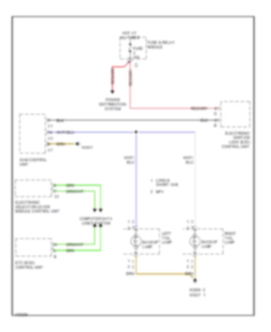
Backup Lamps Wiring Diagram for Mercedes-Benz Sprinter 2014 2500
List of elements for Backup Lamps Wiring Diagram for Mercedes-Benz Sprinter 2014 2500:
- Backup lamp
- Computer data lines system
- Electronic ignition lock (ezs) control unit
- Electronic selector lever module control unit
- Etc (egs) control unit
- Fuse & relay module
- Fuse 10a
- Hot at all times
- Left tail lamp
- Long &
- Mpv
- Power distribution system
- Right tail lamp
- Sam control unit
- Short cab
- W29/8
- W43/1
- W52/7
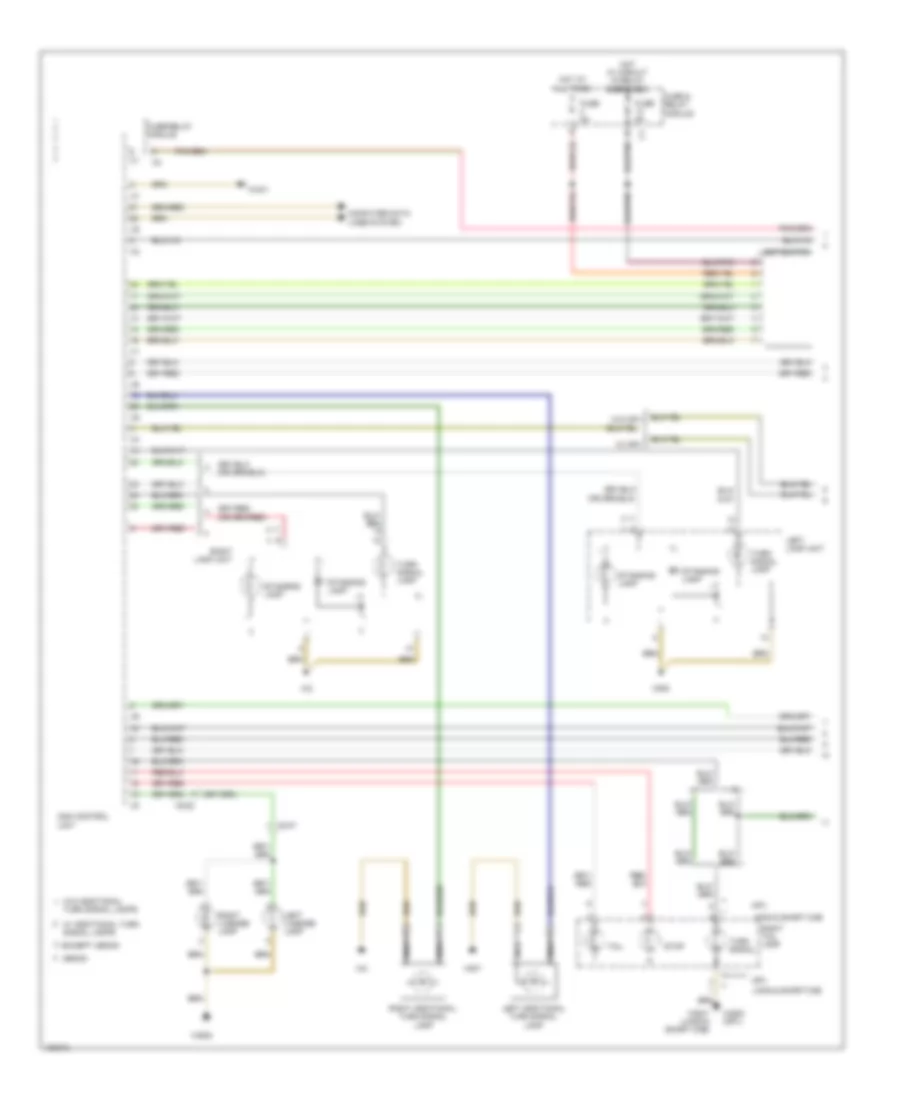
Exterior Lamps Wiring Diagram (1 of 2) for Mercedes-Benz Sprinter 2014 2500
List of elements for Exterior Lamps Wiring Diagram (1 of 2) for Mercedes-Benz Sprinter 2014 2500:
- Computer data lines system
- Except xenon
- Fuse & relay module
- Fuse 5a
- Fuse/relay module
- Hot at all times
- Hot w/ circuit 15 relay energized
- Left additional turn signal lamp
- Left lamp unit
- Left license lamp
- Light switch
- Long & short cab
- Mpv
- Nca
- Right additional turn signal lamp
- Right lamp unit
- Right license lamp
- Right tail lamp
- Sam control unit
- Standing lamp
- Stop
- Tail
- Turn signal
- Turn signal lamp
- Turn signal lamps
- W/ additional turn signal lamps
- W/ mpv
- W/o additional
- W/o mpv
- W29/8
- W29/8 (mpv)
- W43/1
- W52/7 (long & short cab)
- W9/6
- W9/7
- X8/22
- X8/47
- Xenon
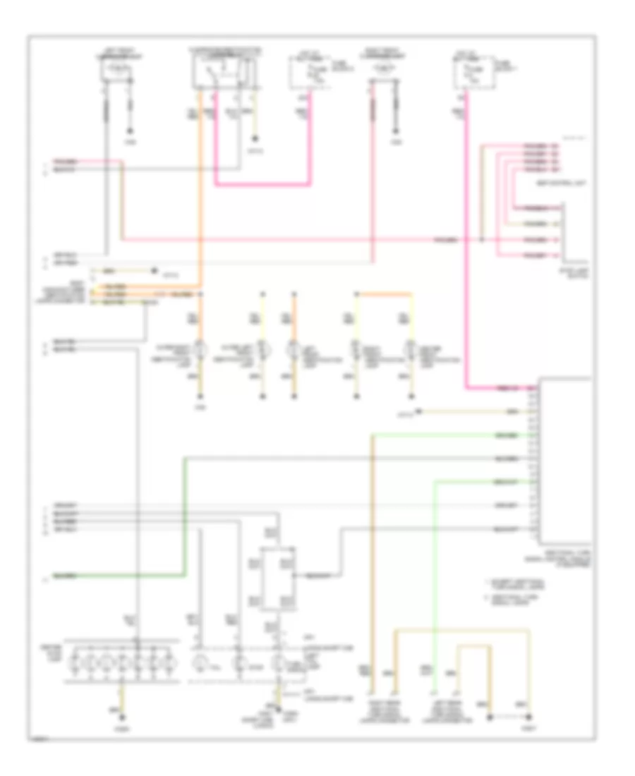
Exterior Lamps Wiring Diagram (2 of 2) for Mercedes-Benz Sprinter 2014 2500
List of elements for Exterior Lamps Wiring Diagram (2 of 2) for Mercedes-Benz Sprinter 2014 2500:
- 20a
- Additional turn signal control module (if equipped)
- Additional turn signal lamps
- Body manufacturer identification lamps connector
- Center front identification lamp
- Center stop lamp
- Clearance/identification lamps relay
- Esp control unit
- Except additional
- Fuse 10a
- Fuse 7.5a
- Fuse block 1
- Fuse block 5
- Hot at all times
- Left front clearance lamp
- Left front identification lamp
- Left rear additional turn signal lamps connector
- Left tail lamp
- Long & short cab
- Mpv
- Outer left front identification lamp
- Outer right front identification lamp
- Right front clearance lamp
- Right front identification lamp
- Right rear additional turn signal lamps connector
- Stop
- Stop lamp switch
- Tail
- Turn signal
- Turn signal lamps
- W29/8
- W29/8 (mpv)
- W38
- W52/7
- W52/7 short cab) (long &
- W71/3
- X18/53
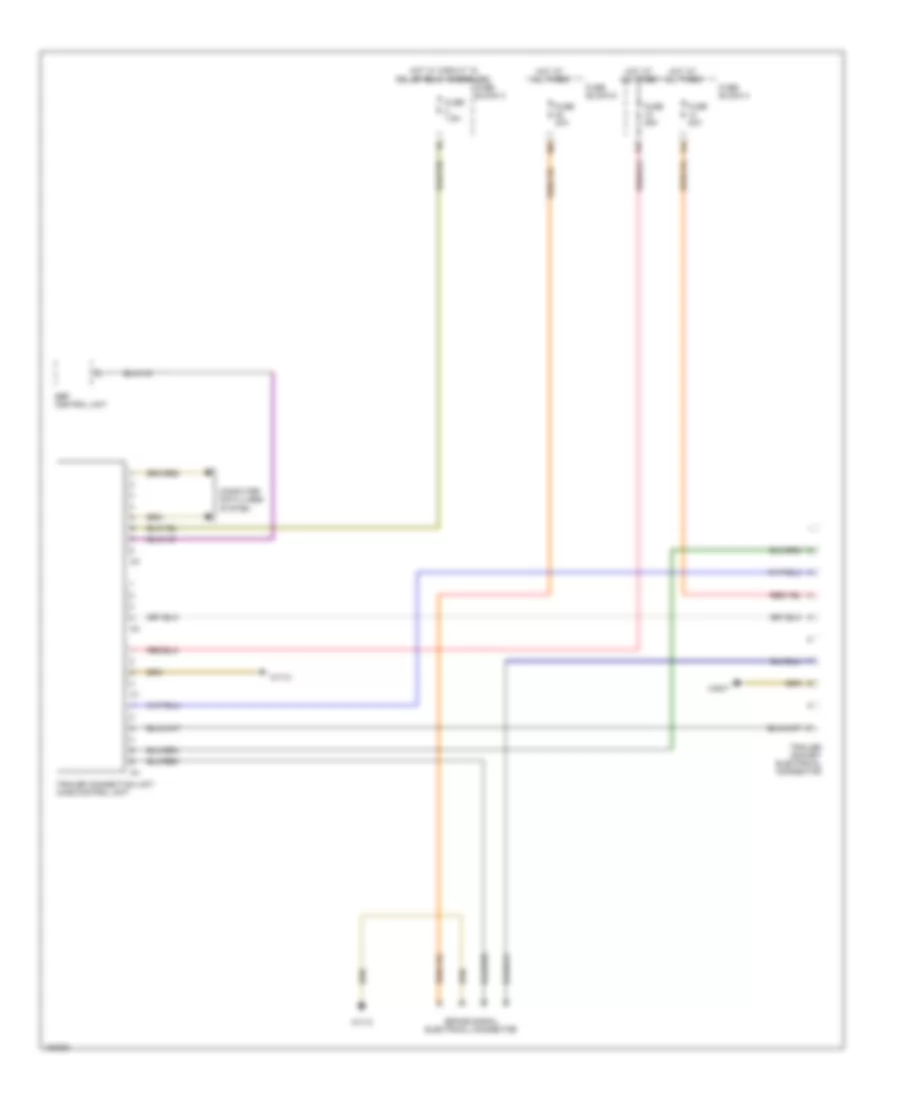
Trailer Tow Wiring Diagram for Mercedes-Benz Sprinter 2014 2500
List of elements for Trailer Tow Wiring Diagram for Mercedes-Benz Sprinter 2014 2500:
- 14a
- 15a
- 30a
- Brake signal electrical connector
- Computer data lines system
- Esp control unit
- Fuse 20a
- Fuse 25a
- Fuse 30a
- Fuse 7.5a
- Fuse block 3
- Fuse block 4
- Fuse block 6
- Hot at all times
- Hot w/ circuit 15 relief relay energized
- Trailer connection unit (aag) control unit
- Trailer socket electrical connector
- W52/7
- W71/3
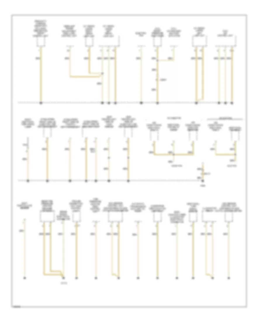
GROUND DISTRIBUTION
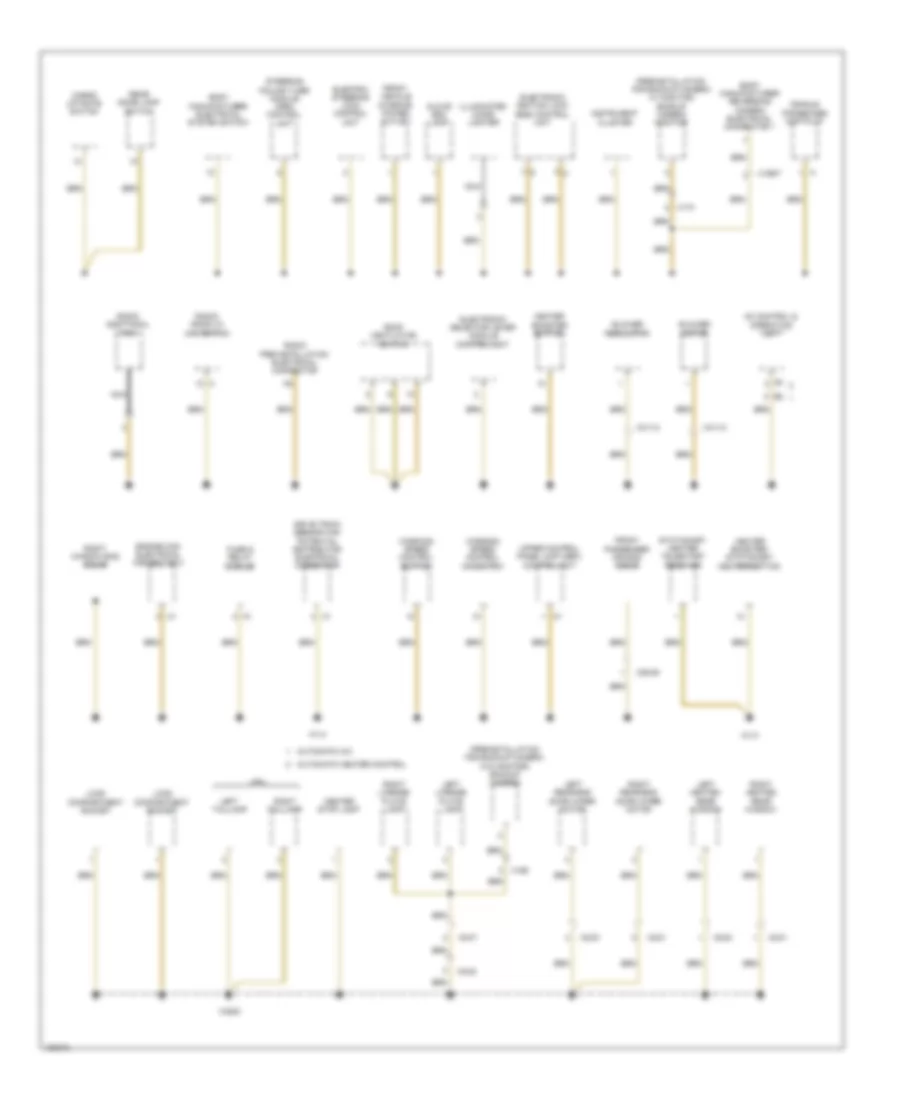
Ground Distribution Wiring Diagram (1 of 5) for Mercedes-Benz Sprinter 2014 2500
List of elements for Ground Distribution Wiring Diagram (1 of 5) for Mercedes-Benz Sprinter 2014 2500:
- (preinstallation for backup camera w/ monitor) backup camera monitor
- (preinstallation for backup camera w/o monitor) backup camera
- Ac control & operating unit
- Automatic a/c
- Automatic heater control
- Blower motor
- Blower regulator
- Body manufacturer electrical system switch
- Body manufacturer reversing camera electrical connector 1
- Cargo liftgate switch
- Center stop lamp
- Cradle for becker map pilot
- Drive train sensor can potential distributor electrical connector
- Electric steering lock control unit
- Electronic ignition lock (ezs) control unit
- Electronic selector lever module control unit
- Engine can electrical connector 2
- Front passenger air bag squib
- Front vehicle interior power outlet
- Fuse & relay module
- Glove box lamp
- Heater booster button
- Heater booster/ stationary heater button
- Illuminated cigar lighter
- Instrument cluster
- Left heated rear window
- Left license plate lamp
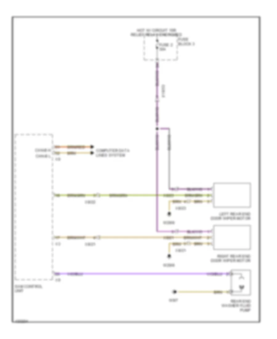
- Left rear-end door wiper motor
- Left taillamp
- Load compartment socket
- Mpv
- Nca
- Radio additional fan
- Radio pre-installation electrical connector
- Radio/ radio w/ navigation
- Rear dome lamp switch
- Right heated rear window
- Right license plate lamp
- Right rear-end door wiper motor
- Right taillamp
- Right window bag squib
- Roof ventilator switch
- Stationary heater telestart receiver
- Steering column tube module (mrm) control unit
- Upper control panel (ucp (obf)) control unit
- W1/3
- W1/4
- W29/8
- Working speed control button
- Working speed control on switch
- X169
- X169/7
- X170
- X28/46
- X31/12
- X8/21
- X8/22
- X8/23
- X8/47
Ground Distribution Wiring Diagram (2 of 5) for Mercedes-Benz Sprinter 2014 2500
List of elements for Ground Distribution Wiring Diagram (2 of 5) for Mercedes-Benz Sprinter 2014 2500:
- (3.0l)
- (3.0l) boost pressure positioner
- (3.0l) cdi control unit
- (proximity warning assistant) collision prevention assist control unit
- (w/ xenon lamps) left lamp unit
- (w/ xenon lamps) left xenon lamp unit
- (w/ xenon lamps) right xenon lamp unit
- Ac duo fan
- Ac mono fan
- Additional fan relay
- Additional fan relay (mono)
- Additional turn signal module
- Air conditioning additional fan 1
- Air conditioning mono fan resistor
- Automatic transmission auxiliary oil pump
- Body manufacturer illumination electrical connector
- Brake signal electrical connector
- Clearance/ identification lamp relay
- Duo fan
- Electric fan
- Headlamp range adjustment (hra (lwr)) control unit
- Illumination relay
- Intake port shutoff actuator
- Mono fan
- Nca
- Nox sensor control unit downstream of scr catalytic converter
- Nox sensor control unit upstream of scr catalytic converter
- Rear tire pressure monitor decoder antenna
- Right additional turn signal lamp
- Soot particulate sensor
- Tire pressure monitor (rdk) control unit
- Trailer connection unit (aag) control unit
- W71/3
- W9/6
- X26/61
- X64/13
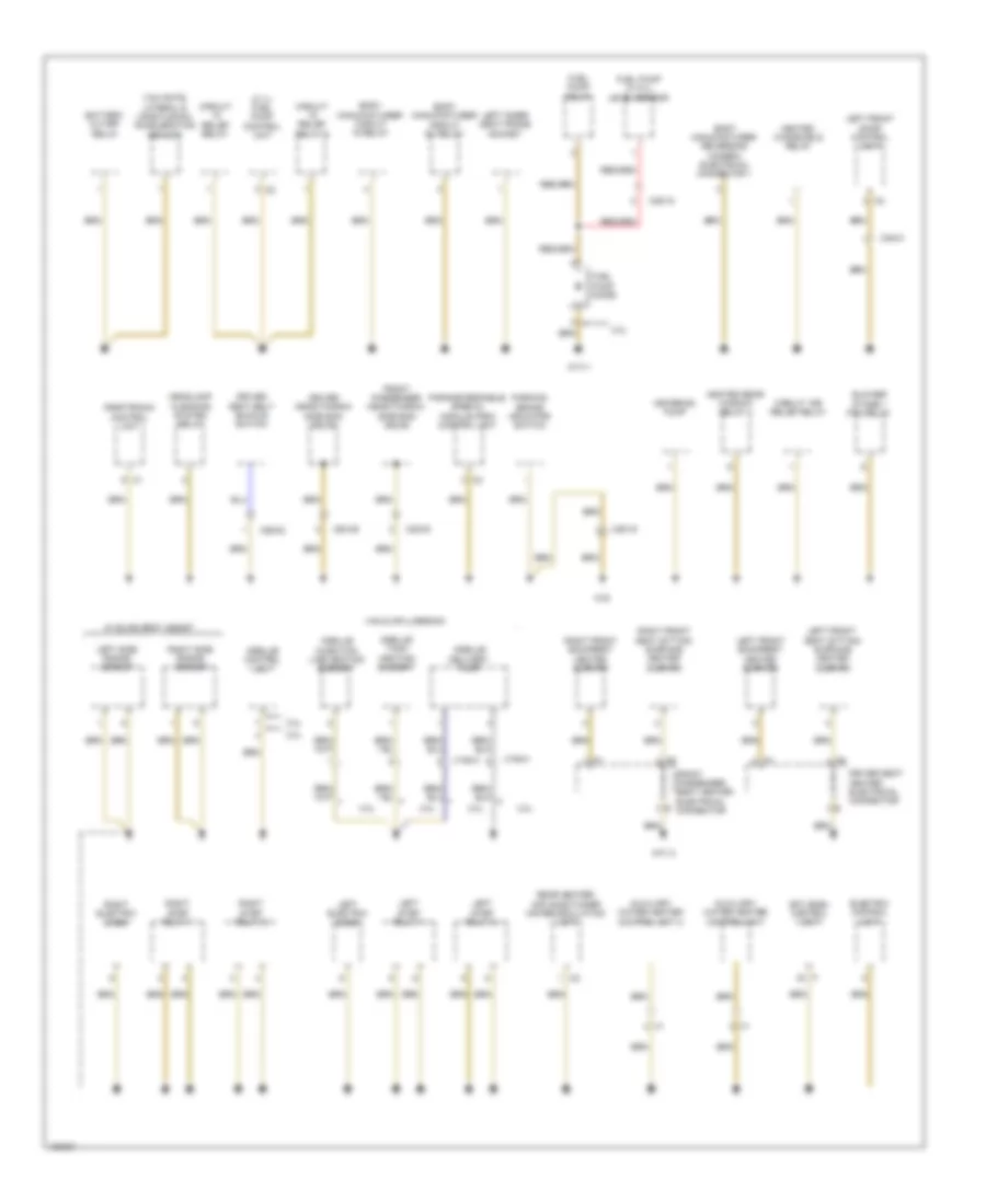
Ground Distribution Wiring Diagram (3 of 5) for Mercedes-Benz Sprinter 2014 2500
List of elements for Ground Distribution Wiring Diagram (3 of 5) for Mercedes-Benz Sprinter 2014 2500:
- (w/ lane keeping & highbeam assist) multi-function camera
- Battery- operated horn
- Center front identification lamp
- Center interior protection sensor
- Circulation pump
- Diagnostic connector (16-pin)
- Dome lamp w/ switch
- Engine hood switch
- Front
- Front interior protection sensor
- Front passenger exit lamp
- Front roof electrical connector
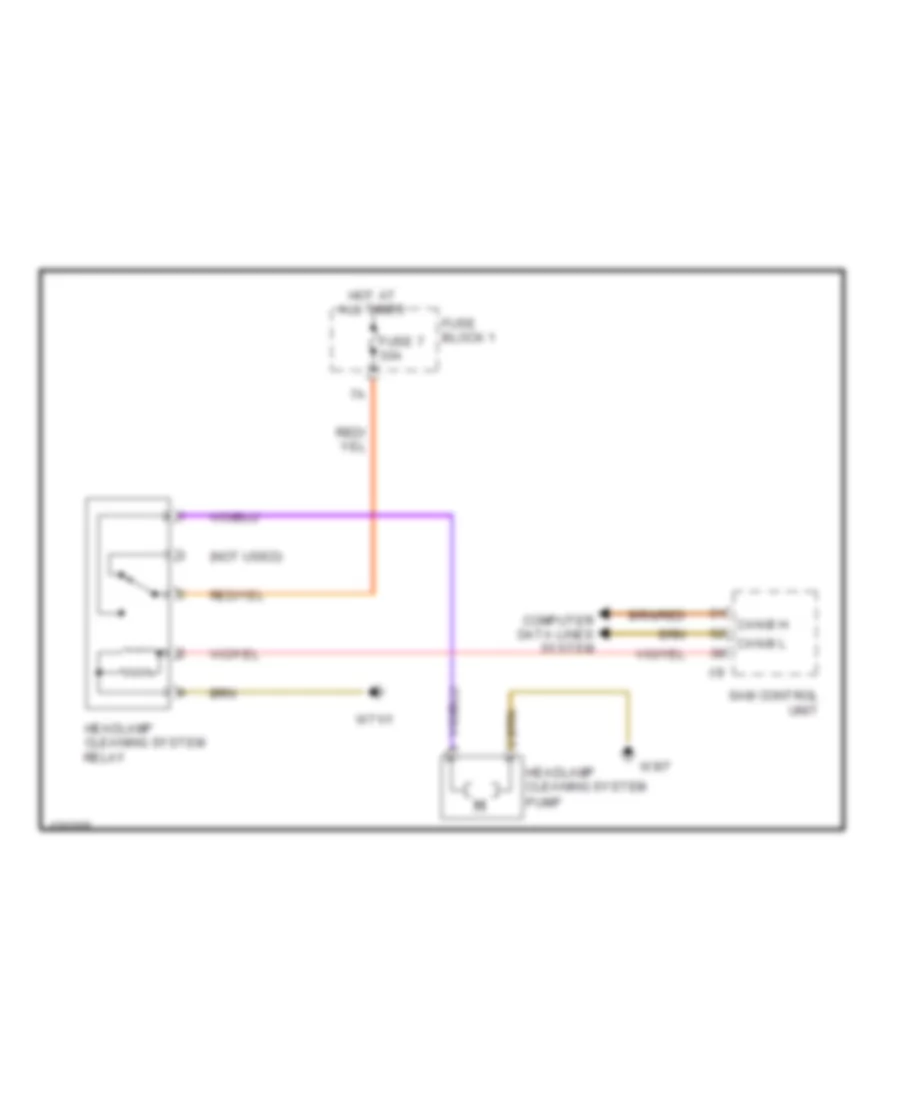
- Headlamp cleaning system pump
- Left additional turn signal lamp
- Left foglamp
- Left front clearance lamp
- Left front identification lamp
- Left window bag squib
- Motion detector
- Nca
- Outer left front identification lamp
- Outer right front identification lamp
- Overhead control panel (ocp (dbe)) control unit
- Passenger- side outside mirror
- Rear end washer fluid pump
- Rear heavy duty automatic air conditioning recirculation unit
- Rear interior protection sensor
- Right front clearance lamp
- Right front identification lamp
- Roof additional relay fan
- Roof air conditioner additional fan 2
- Sam control unit
- Signalling horn
- W38
- W43/1
- W9/7
- Windshield washer system pump
- Wiper motor
- X34/36
- X35/2
- X42/28
- X64/14
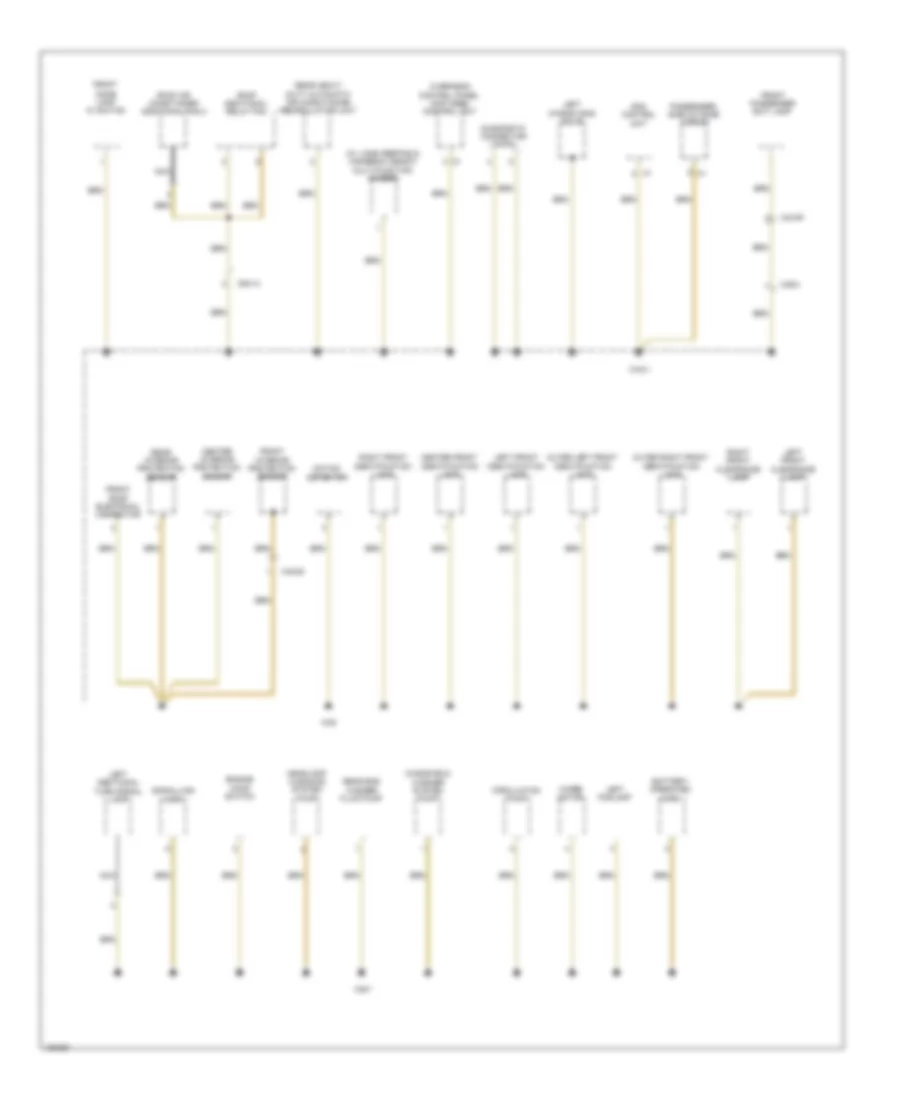
Ground Distribution Wiring Diagram (4 of 5) for Mercedes-Benz Sprinter 2014 2500
List of elements for Ground Distribution Wiring Diagram (4 of 5) for Mercedes-Benz Sprinter 2014 2500:
- (2.1l) fuel pump control unit
- 3.0l
- Auxiliary water heater control unit
- Auxiliary water heater control unit 2
- Battery cutoff relay
- Blower stage 1 fan relay
- Body manufacturer circuit 15 relay
- Body manufacturer circuit d+ relay
- Body manufacturer reversing camera electrical connector 1
- Circuit 15r relief relay
- Circuit relief relay
- Circuit relief relay 2
- Connector
- Driver head/thorax side bag squib
- Driver seat belt buckle switch
- Driver seat heater electrical connector
- Electric control unit
- Etc (egs) control unit
- Front passenger head/thorax side bag squib
- Front passenger seat heater electrical e
- Fuel pump diode
- Fuel pump relay
- Fuel pump w/ fill level sensor
- Headlamp cleaning system relay
- Heated rear window relay 1
- Heated windshield relay
- Left electric step
- Left front backrest heated cushion
- Left front door control unit
- Left front seat sitting surface heated cushion
- Left inner seat frame socket
- Left side radar sensor
- Left step relay 1
- Left step relay 2
- Metering pump
- Parameterizable special module (psm) control unit
- Parking brake indicator switch
- Parktronic control unit
- Rear heater/ air conditioner air recirculation unit
- Right electric step
- Right front backrest heated cushion
- Right front seat sitting surface heated cushion
- Right side radar sensor
- Right step relay 1
- Right step relay 2
- Van & mpv version
- W/ blind spot assist
- W33
- W71/1
- W71/2
- X194/3
- X194/4
- X25/15
- X25/16
- X28/29
- X28/30
- X35/41
- X55/32
- Yaw rate, lateral & longitudinal acceleration sensor
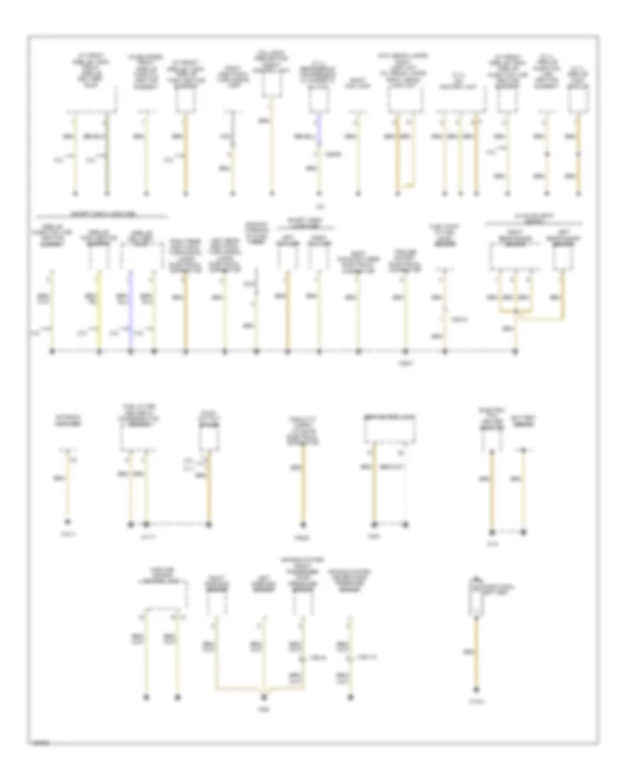
Ground Distribution Wiring Diagram (5 of 5) for Mercedes-Benz Sprinter 2014 2500
List of elements for Ground Distribution Wiring Diagram (5 of 5) for Mercedes-Benz Sprinter 2014 2500:
- (2.1l) cdi control unit
- (2.1l) refrigerant compressor w/ magnetic clutch
- (short cab & long cab)
- (w/ blind spot assist)
- (w/o xenon lamps) right lamp unit (w/ xenon lamps) right xenon lamp unit
- 2.1l
- 3.0l
- Additional battery
- Air bag system driver door pressure sensor
- Air bag system front passenger door pressure sensor
- Antenna amplifier
- Backup warning system horn
- Battery sensor
- Body manufacturer electrical connector
- Circuit 31 cargo liftgate electrical connector
- Collision prevention assist control unit
- Electric ptc heater booster
- Esp control unit
- Fuel filter heater w/ condensation sensor
- Fuel pump w/ fuel level sensor
- Glow out put stage
- Highline air bag control unit
- Left rear additional turn signal lamps electrical connector
- Left rear radar sensor
- Left side bag sensor
- Left taillamp
- Nca
- Right additional turn signal lamp
- Right fog lamp
- Right rear additional turn signal lamps electrical connector
- Right rear radar sensor
- Right side bag sensor
- Right taillamp
- Short cab & (long cab)
- Trailer socket electrical connector
- W10
- W10/4
- W11/1
- W26
- W31/1
- W52/7
- W52/8
- W9/3
- X25/15
- X26/65
- X35/110
- X35/44
HEADLIGHTS
Adaptive Front Lighting Wiring Diagram for Mercedes-Benz Sprinter 2014 2500
List of elements for Adaptive Front Lighting Wiring Diagram for Mercedes-Benz Sprinter 2014 2500:
- Can-c h
- Can-c l
- Computer data lines system
- Front axle headlamp range adjustment level sensor
- Fuse & relay module
- Fuse 5a
- Headlamp range adjustment (hra (lwr)) control unit
- Hot w/ circuit 15 relay energized
- Left xenon lamp unit
- Pwm 2
- Rear axle headlamp range adjustment level sensor
- Right xenon lamp unit
- W9/6
- X62/72
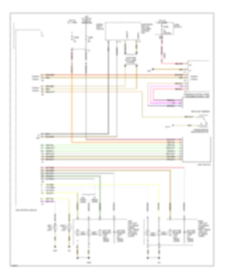
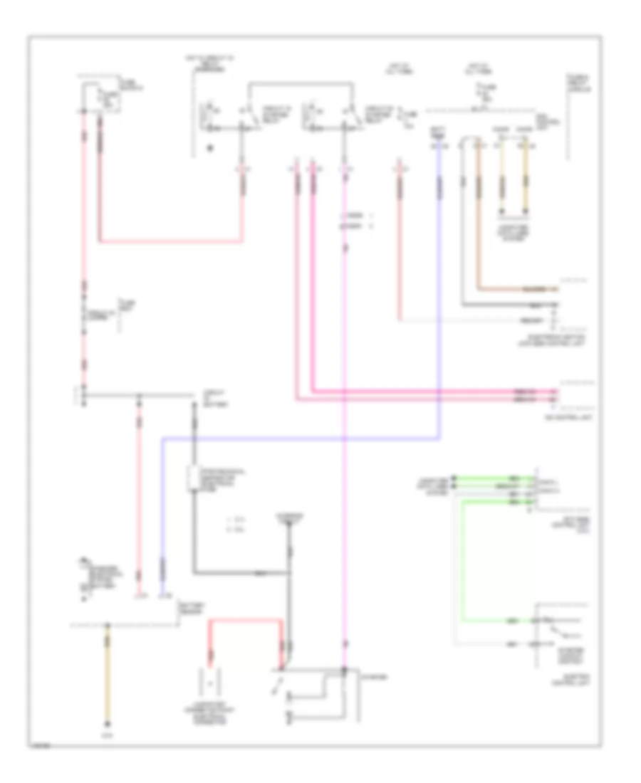
Headlamps Wiring Diagram for Mercedes-Benz Sprinter 2014 2500
List of elements for Headlamps Wiring Diagram for Mercedes-Benz Sprinter 2014 2500:
- (or 19b) 19a
- 15r
- Can-b h
- Can-b l
- Computer data lines system
- Daytime running lamp (w/ xenon lamps)
- Daytime running lamp (w/o xenon lamps)
- Electronic ignition lock (ezs) control unit
- Fuse & relay module
- Fuse 5a
- Fuse 5a (or 25a)
- Fuse block 5
- High beam
- Hot at all times
- Hot w/ circuit 15 relay energized
- Left fog lamp
- Left lamp unit (w/o xenon lamps) left xenon lamp unit (w/ xenon lamps)
- Light switch
- Low beam
- Overhead control panel (ocp [dbe]) control unit
- Parking brake indicator switch
- Rain/light sensor
- Right fog lamp
- Right lamp unit (w/o xenon lamps) right xenon lamp unit (w/ xenon lamps)
- Sam control module
- W/ xenon lamps
- W/o xenon lamps
- W38
- W71/1
- W9/6
- W9/7
- X18/53
HORN
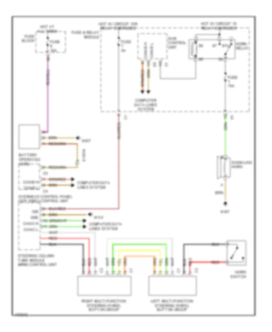
Horn Wiring Diagram for Mercedes-Benz Sprinter 2014 2500
List of elements for Horn Wiring Diagram for Mercedes-Benz Sprinter 2014 2500:
- 15r
- 87a
- Battery operated horn
- Can-b h
- Can-b l
- Can-c h
- Can-c l
- Computer data lines system
- Fuse & relay module
- Fuse 15a
- Fuse 5a
- Fuse block
- Gnd
- Horn relay
- Horn switch
- Hot at all times
- Hot w/ circuit 15 relay energized
- Hot w/ circuit 15r relay energized
- Left multi-function steering wheel button group
- Overhead control panel (ocp (dbe)) control unit
- Red
- Right multi-function steering wheel button group
- Sam control unit
- Signaling horn
- Steering column tube module (mrm) control unit
- W1/3
- W9/7
- X18/54
INSTRUMENT CLUSTER
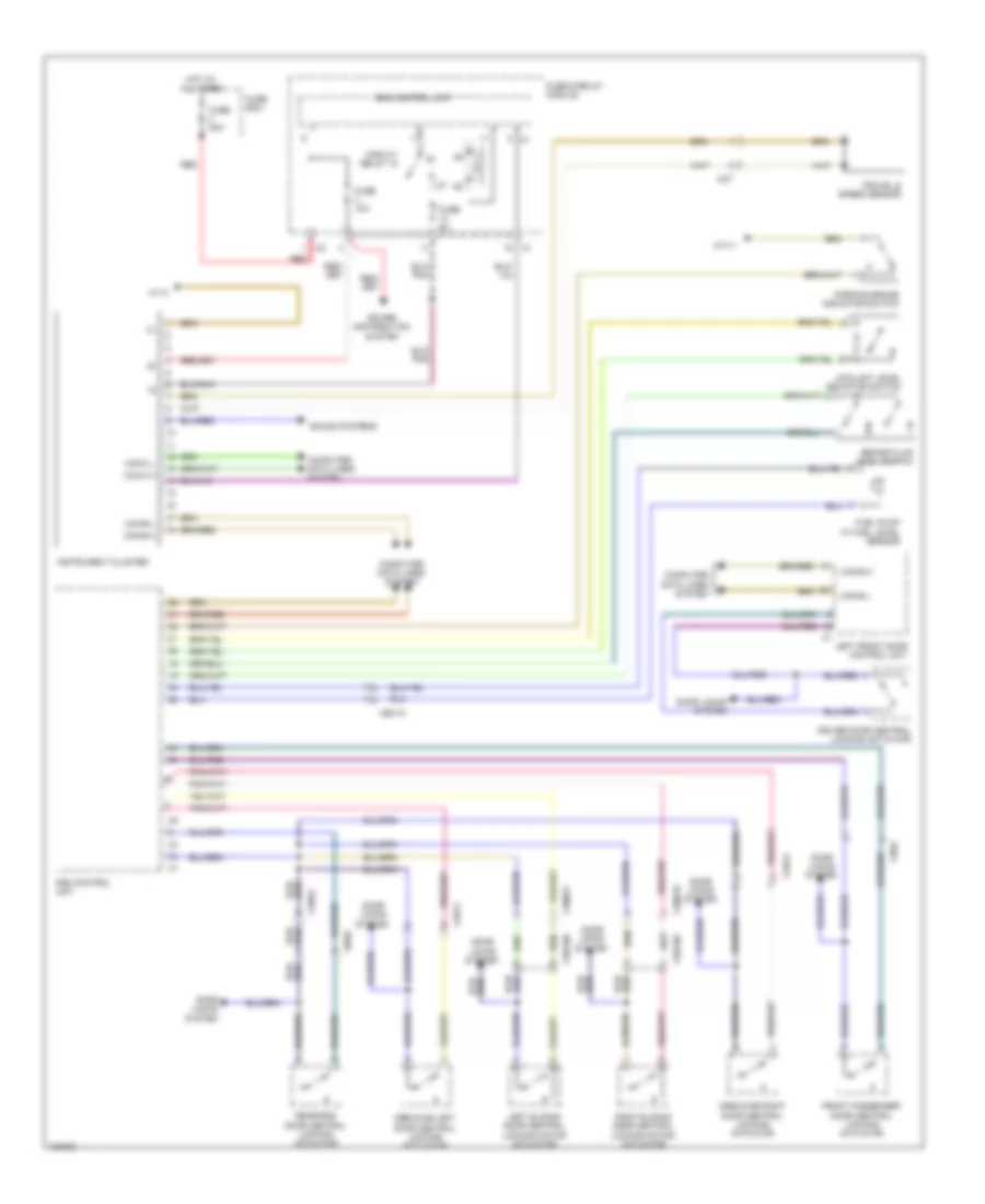
Instrument Cluster Wiring Diagram for Mercedes-Benz Sprinter 2014 2500
List of elements for Instrument Cluster Wiring Diagram for Mercedes-Benz Sprinter 2014 2500:
- Brake fluid level switch
- Can-b h
- Can-b l
- Can-c h
- Can-c l
- Circuit relay 15
- Computer data lines system
- Coolant level indicator switch
- Crewcab left door central locking actuator
- Crewcab right door central locking actuator
- Door locks system
- Driver door central locking actuator
- Front passenger door central locking actuator
- Fuel pump w/ fuel level sensor
- Fuse & relay module
- Fuse 10a
- Fuse 5a
- Fuse 80a
- Fuse box
- Hot at all times
- Instrument cluster
- Left front door control unit
- Left sliding door central locking motor actuator
- Parking brake indicator switch
- Power distribution system
- Rear-end door central locking actuator
- Red
- Right sliding door central locking motor actuator
- Sam control unit
- Sound systems
- Travel & speed sensor
- W1/3
- W71/1
- X100/19
- X100/21
- X18/52
- X2/7
- X25/15
- X35/108
- X35/109
- X35/2
- X43/11
- X43/12
- X8/20
INTERIOR LIGHTS
Interior Lights Wiring Diagram (1 of 3) for Mercedes-Benz Sprinter 2014 2500
List of elements for Interior Lights Wiring Diagram (1 of 3) for Mercedes-Benz Sprinter 2014 2500:
- 17a
- Computer data lines system
- Cornering illumination
- Door locks system
- Driver door central locking actuator
- Driver door control unit
- Driver exit lamp
- Front passenger door central locking actuator
- Front passenger entry/ exit lamp
- Fuse & relay module
- Fuse 10a
- Fuse 15a
- Fuse 5a
- Fuse block 2
- Glove box lamp
- Hot at all times
- Hot w/ circuit 15 relay energized
- Hot w/ circuit 15r relay energized
- Left crewcab door central locking actuator
- Left sliding door central locking motor actuator
- Left xenon lamp unit
- Light switch
- Rear-end door central locking actuator
- Red
- Right crewcab door central locking actuator
- Right sliding door central locking motor actuator
- Right xenon lamp unit
- Sam control unit
- W/ sliding door
- W/ xenon lamps
- W/o sliding door
- W1/3
- W43/1
- W9/6
- X100/19
- X100/21
- X18/52
- X34/35
- X34/36
- X35/108
- X35/109
- X35/2
- X35/43
- X43/11
- X43/12
- X8/20
Interior Lights Wiring Diagram (2 of 3) for Mercedes-Benz Sprinter 2014 2500
List of elements for Interior Lights Wiring Diagram (2 of 3) for Mercedes-Benz Sprinter 2014 2500:
- Base lighting
- Body manufacturer electrical system switch
- Dome lamp 1 (panel van w/o headliner)
- Dome lamp 2 (panel van w/o headliner)
- Electronic selector lever module control unit
- Except short cab
- Illumination relay
- Left load compartment lamp (panel van w/o headliner)
- Premium lighting
- Radio preinstallation connector
- Rear dome lamp 3 w/ switch (panel van w/ headliner & mpv)
- Rear dome lamp switch (panel van w/ headliner & mpv)
- Rear load compartment lamp (panel van w/o headliner)
- Red
- Right load compartment lamp 1 (panel van w/o headliner)
- Right load compartment lamp 2 (panel van w/o headliner)
- Short cab
- W1/3
- W71/3
- Working speed control on switch
- X18/51
- X18/53
Interior Lights Wiring Diagram (3 of 3) for Mercedes-Benz Sprinter 2014 2500
List of elements for Interior Lights Wiring Diagram (3 of 3) for Mercedes-Benz Sprinter 2014 2500:
- (panel van w/ headliner & mpv) rear dome lamp 2
- (panel van w/ headliner & mpv) rear dome lamp 2 w/ switch
- (panel van w/ headliner & mpv) rear dome lamp 3
- (panel van w/ headliner & mpv) rear dome lamp 4
- (panel van w/ headliner & mpv) rear dome lamp w/ switch
- A/c control & operating unit
- Cargo liftgate switch
- Control button
- Except short cab
- Front dome lamp w/ switch
- Front passenger side power window switch
- Heater booster button
- Heater booster/ stationary heater button
- Illuminated cigar lighter
- Nca
- Rear dome lamp (long cab, panel van w/ headliner & mpv)
- Red
- Roof ventilator switch
- Short cab
- W1/3
- W38
- Working speed
- X18/56
- X35/2
NAVIGATION
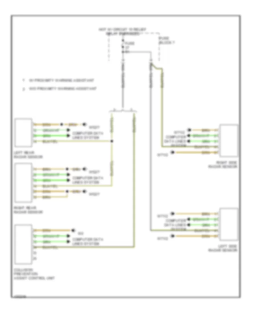
Blind Sport Information System Wiring Diagram for Mercedes-Benz Sprinter 2014 2500
List of elements for Blind Sport Information System Wiring Diagram for Mercedes-Benz Sprinter 2014 2500:
- 37a
- 37b
- Collision prevention assist control unit
- Computer data lines system
- Fuse 5a
- Fuse block 7
- Hot w/ circuit 15 relief relay energized
- Left rear radar sensor
- Left side radar sensor
- Right rear radar sensor
- Right side radar sensor
- W/ proximity warning assistant
- W/o proximity warning assistant
- W52/7
- W71/2
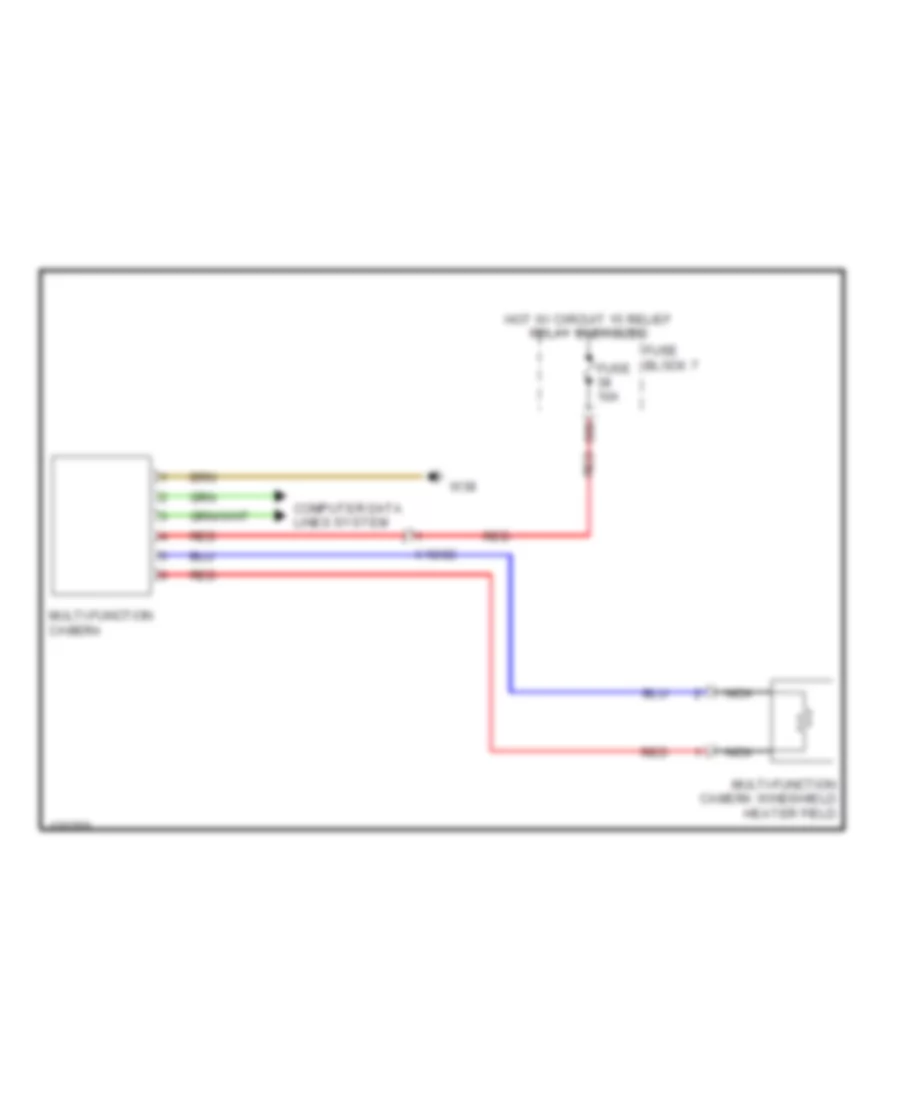
Multi-function Camera Wiring Diagram for Mercedes-Benz Sprinter 2014 2500
List of elements for Multi-function Camera Wiring Diagram for Mercedes-Benz Sprinter 2014 2500:
- 38b
- Computer data lines system
- Fuse 10a
- Fuse block 7
- Hot w/ circuit 15 relief relay energized
- Multi-function camera
- Multi-function camera windshield heater field
- Nca
- Red
- W38
- X18/82
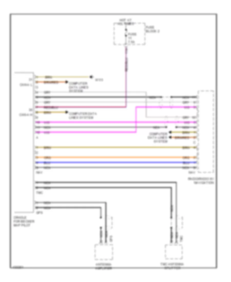
Navigation Wiring Diagram for Mercedes-Benz Sprinter 2014 2500
List of elements for Navigation Wiring Diagram for Mercedes-Benz Sprinter 2014 2500:
- 11a
- Antenna amplifier
- Can-a h
- Can-a l
- Computer data lines system
- Cradle for becker map pilot
- Fuse 7.5a
- Fuse block 2
- Gps
- Hot at all times
- Nav
- Nca
- Radio/radio w/ navigation
- Tmc
- Tmc antenna splitter
- W1/3
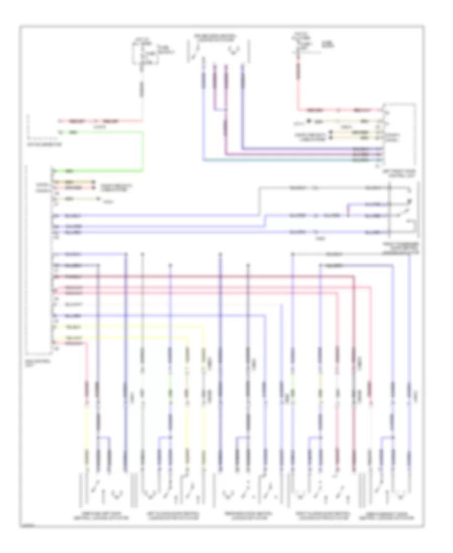
Parking Assistant Wiring Diagram (1 of 2) for Mercedes-Benz Sprinter 2014 2500
List of elements for Parking Assistant Wiring Diagram (1 of 2) for Mercedes-Benz Sprinter 2014 2500:
- Can-c h
- Can-c l
- Center front parktronic warning element
- Computer data lines system
- Driver side outside mirror
- Fuse 10a
- Fuse block 3
- Hot w/ circuit 15 relief relay energized
- Inner left rear parktronic sensor
- Inner right rear parktronic sensor
- Outer left rear parktronic sensor
- Parktronic control unit
- Parktronic warning buzzer
- Passenger side outside mirror
- W71/1
- X18/56
- X26/27
- X35/28
Parking Assistant Wiring Diagram (2 of 2) for Mercedes-Benz Sprinter 2014 2500
List of elements for Parking Assistant Wiring Diagram (2 of 2) for Mercedes-Benz Sprinter 2014 2500:
- Center left front parktronic sensor
- Center right front parktronic sensor
- Inner left front parktronic sensor
- Inner right front parktronic sensor
- Outer left front parktronic sensor
- Outer right front parktronic sensor
- Outer right rear parktronic sensor
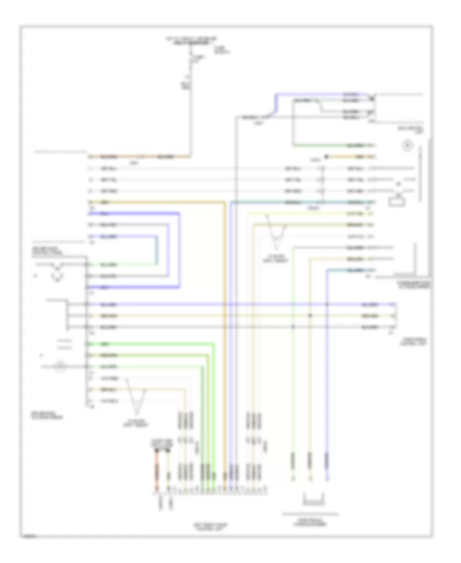
Rear Camera Wiring Diagram for Mercedes-Benz Sprinter 2014 2500
List of elements for Rear Camera Wiring Diagram for Mercedes-Benz Sprinter 2014 2500:
- Backup camera (preinstallation for backup camera w/o monitor)
- Backup camera monitor (preinstallation for backup camera w/ monitor)
- Backup warning system horn
- Body manufacturer reversing camera electrical connector 1
- Body manufacturer reversing camera electrical connector 2
- Cam
- Computer data lines system
- Exterior lights system
- Front roof electrical connector
- Fuse 5a
- Fuse block 3
- Hot w/ circuit 15 relief relay energized
- Nca
- Nca x169/1
- Pnk
- Radio/radio w/ navigation
- Sam control unit
- Sound systems
- W/ backup camera
- W/ backup camera monitor
- W/o backup camera
- W/o backup camera monitor
- W1/3
- W29/8
- W52/7
- W71/1
- X169
- X169/2
- X169/6
- X169/7
- X170
- X170/1
- X18/52
- X18/54
POWER DISTRIBUTION
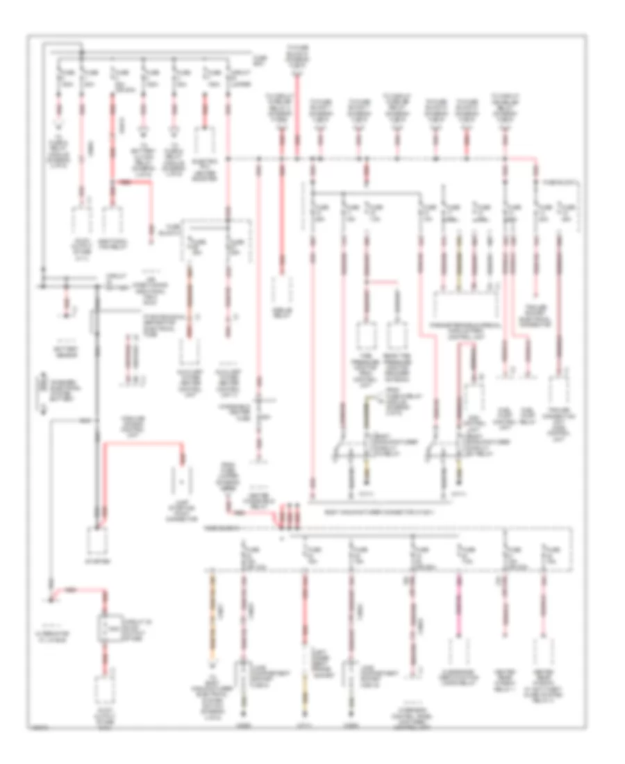
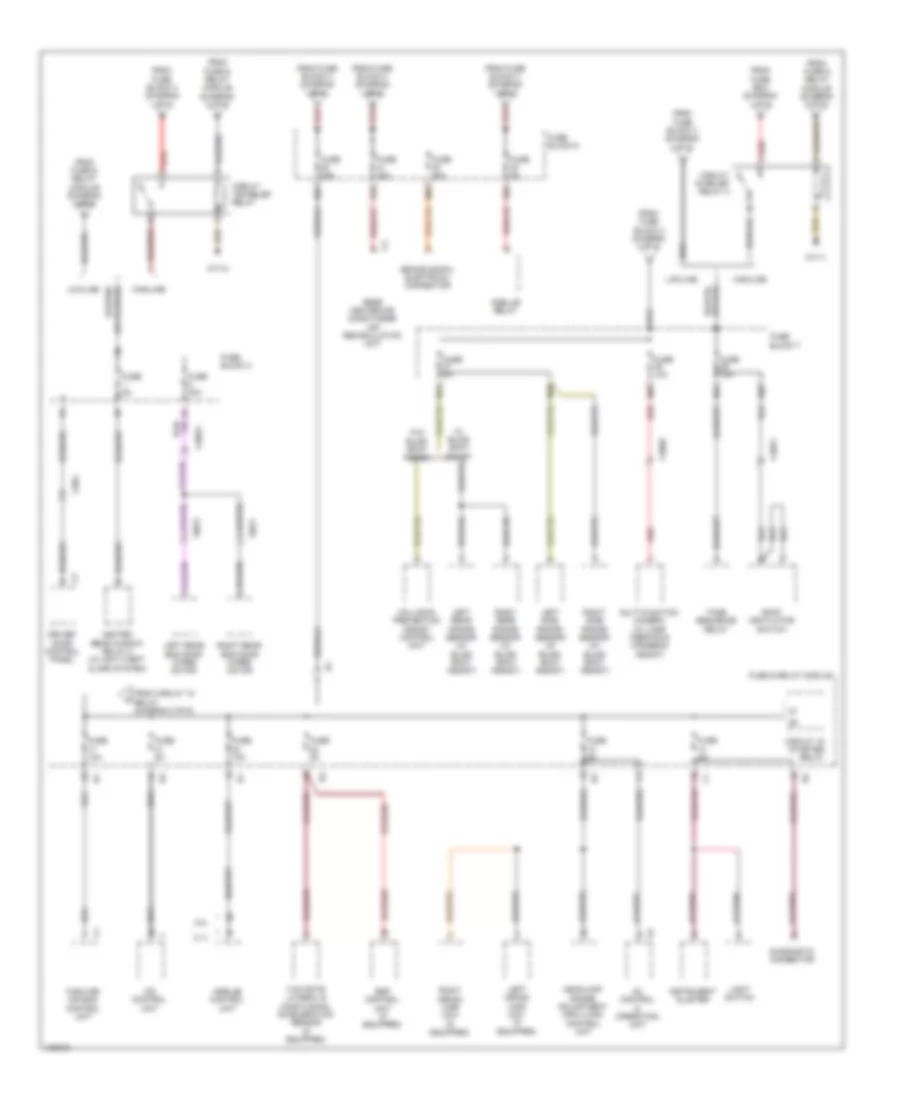
Power Distribution Wiring Diagram (1 of 6) for Mercedes-Benz Sprinter 2014 2500
List of elements for Power Distribution Wiring Diagram (1 of 6) for Mercedes-Benz Sprinter 2014 2500:
- (or 19b) 19a
- (or 21b) 21a
- 100a
- 10a
- 11a
- 12a
- 13a
- 13b
- 14a
- 15a
- 16b
- 17a
- 17b
- 18a
- 18b
- 20a
- 22a
- 23a
- 23b
- 24a
- 25a
- 26a
- 27b
- 80a
- Additional fan relay
- Air conditioning additional fan 2 (duo)
- Alternator w/ lin bus
- Auxiliary water heater control unit
- Auxiliary water heater control unit 2
- Battery sensor
- Body manufacturer circuit 15 relay
- Body manufacturer circuit d+ relay
- Body manufacturer connector (x145/1)
- Circuit 30 glow output stage
- Circuit battery
- Circuit jumper
- Clearance/ identification lamps relay
- Electric ptc heater booster
- From fuse & relay module (diagram 2 of 6)
- From fuse/ jumper (diagram 3 of 6)
- Fuel pump control unit
- Fuel pump relay
- Fuse 10a
- Fuse 150a
- Fuse 15a
- Fuse 15a (or 10a)
- Fuse 15a (or 30a)
- Fuse 20a
- Fuse 25a
- Fuse 5a (or 25a)
- Fuse 7.5a
- Fuse 80a
- Fuse 80a (or 20a)
- Fuse block 4
- Fuse block 5
- Fuse box
- Glow output stage (2.1l)
- Glow output stage (3.0l)
- Heated rear window relay 1
- Heated rear window w/ anti-theft alarm system relay 2
- Heated windshield relay
- Highline air bag control unit
- Jump starting point connector
- Left inner seat frame socket
- Load compartment socket (x58/15)
- Load compartment socket (x58/4)
- On-board electrical system battery
- Overhead control panel (ocp (dbe)) control unit
- Parameterizable special module (psm) control unit
- Pyrotechnical separator electrical fuse
- Rear tire pressure monitor decoder antenna
- Red
- Sam control unit
- Starter
- Tire pressure monitor (rdk) control unit
- To battery cutoff relay (diagram 3 of 6)
- To body manufacturer electrical system switch (diagram 4 of 6)
- To circuit 15 relief relay (diagram 2 of 6)
- To circuit 15 relief relay 2 (diagram 5 of 6)
- To circuit 15r relief relay (diagram 5 of 6)
- To fuse & relay module (diagram 2 of 6)
- To fuse & relay module (diagram 3 of 6)
- To fuse block 6 (diagram 5 of 6)
- To fuse block 7 (diagram 3 of 6)
- Trailer connection unit (aag) control unit
- Trailer socket electrical connector
- W29/8
- W71/1
- Windshield heater fuse
- X18/53
- X18/77
- X26/64
- X64/13
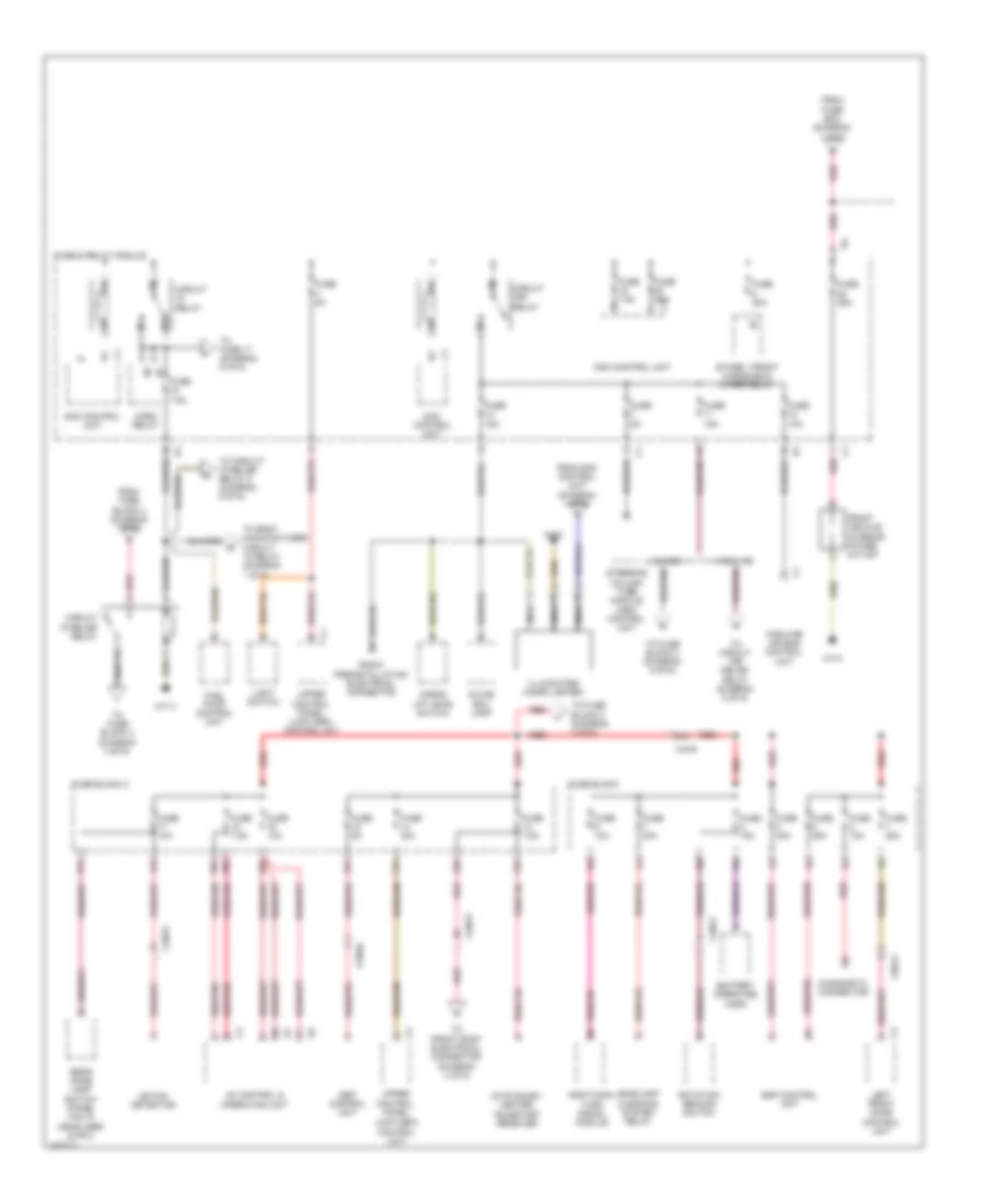
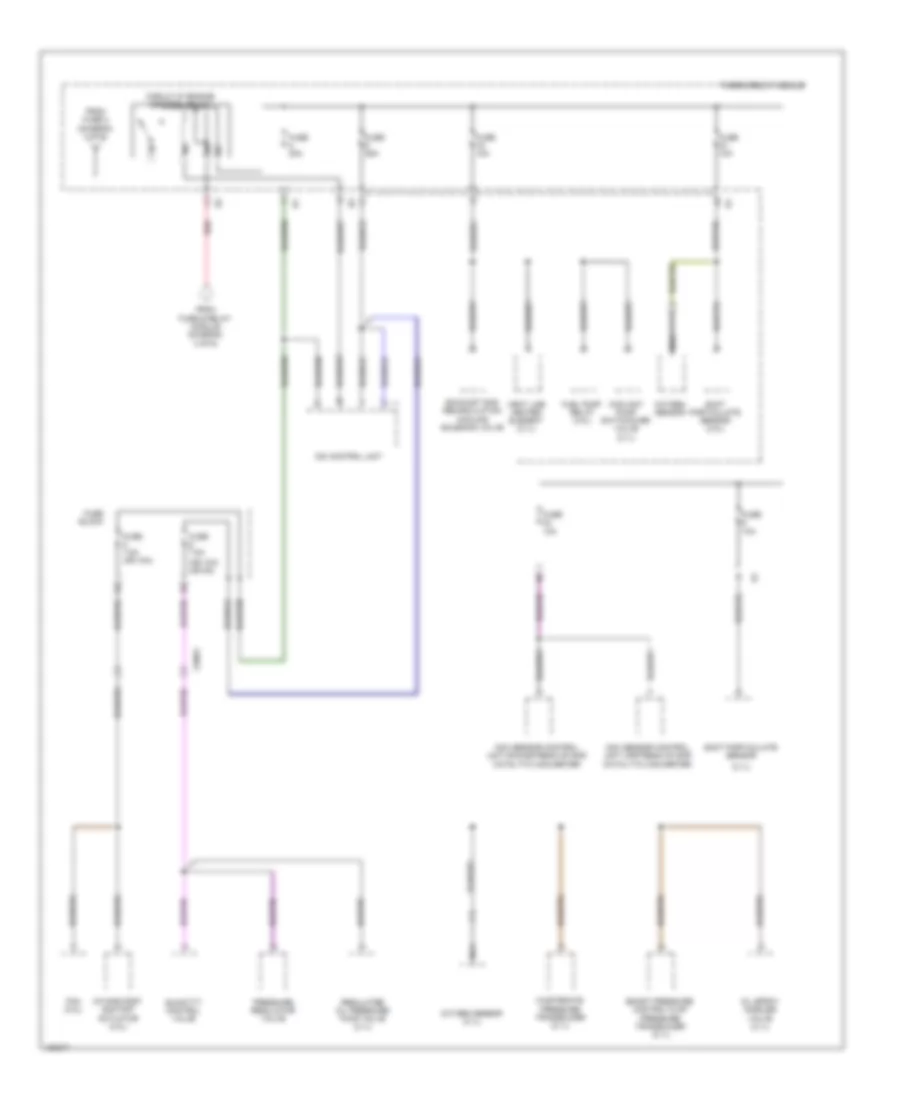
Power Distribution Wiring Diagram (2 of 6) for Mercedes-Benz Sprinter 2014 2500
List of elements for Power Distribution Wiring Diagram (2 of 6) for Mercedes-Benz Sprinter 2014 2500:
- (ucp (obf)) control unit
- 13a
- 13b
- 14a
- 15a
- 16a
- 17a
- 17b
- 18a
- 18b
- 87a
- Ac control & operating unit
- Additional turn signal module
- Battery operated horn
- Cargo lift gate switch
- Circuit 15 relief relay
- Circuit 15r relay
- Circuit relay
- Diagnostic connector
- Esp control unit
- From fuse block 4 (diagram 1 of 6)
- From fuse box (diagram 1 of 6)
- From sam control unit (diagram 4 of 6)
- Front vehicle interior power outlet
- Fuel pump control unit
- Fuse & relay module
- Fuse 10a
- Fuse 15a
- Fuse 25a
- Fuse 30a
- Fuse 40a
- Fuse 5a
- Fuse 7.5a
- Fuse block
- Fuse block 2
- Glove box lamp
- Headlamp cleaning system relay
- Highline
- Highline air bag control unit
- Horn relay
- Illuminated cigar lighter
- Left front door control unit
- Light switch
- Lowline
- Motion detector
- N/a
- Nca
- Radio preinstallation electrical connector
- Rear dome lamp switch (panel van w/ headliner & mpv)
- Red
- Red/pnk
- Rotating beacon switch
- Sam control unit
- Stage 1 front windshield wiper relay
- Stationary heater telestart receiver
- Steering column tube module (mrm) control unit
- To body manufacturer circuit 15 relay (diagram 1 of 6)
- To circuit 15 relief relay 2 (diagram 5 of 6)
- To circuit 15r relief relay (diagram 5 of 6)
- To front roof electrical connector (diagram 4 of 6)
- To fuse 17 (diagram 5 of 6)
- To fuse block 2 (diagram 3 of 6)
- To fuse block 3 (diagram 4 of 6)
- To fuse block 3 (diagram 5 of 6)
- Upper control panel
- Upper control panel (ucp (obf)) control init
- W1/3
- W71/1
- X18/56
- X18/75
- X18/77
- X35/41
- X4/49
Power Distribution Wiring Diagram (3 of 6) for Mercedes-Benz Sprinter 2014 2500
List of elements for Power Distribution Wiring Diagram (3 of 6) for Mercedes-Benz Sprinter 2014 2500:
- (not used)
- 100a
- 10a
- 10b
- 11a
- 12a
- 12b
- 15r
- 250a
- 42a
- 43a
- 43b
- 44a
- 44b
- 45a
- 45b
- Additional battery (if equipped)
- Battery cutoff relay
- Blower motor
- Blower regulator
- Blower stage 1 fan relay
- Can-b h
- Can-b l
- Can-c h
- Can-c l
- Can-d h
- Can-d l
- Circuit 30 cargo liftgate electrical connector
- Cluster
- Cradle for becker map pilot
- Diagnostic connector
- Electric steering lock control unit
- Electrical fuse
- Electronic ignition lock (ezs) control unit
- Electronic selector lever module control unit
- Engine can electrical connector 2
- Fbs wire antenna terminal connector
- From fuse block 2 (diagram 2 of 6)
- From fuse box (diagram 1 of 6)
- Fuse & relay module
- Fuse 10a
- Fuse 15a (or 20a)
- Fuse 25a
- Fuse 30a
- Fuse 5a
- Fuse 7.5a
- Fuse block 2
- Fuse block 7
- Fuse/ jumper
- Hydraulic pump preinstallation electrical connector
- Instrument
- Interior can electrical connector
- Left step relay 1
- Left step relay 2
- Left step warning buzzer
- N/a
- Radio preinstallation electrical connector
- Radio/radio w/ navigation
- Rear heavy-duty automatic air conditioning air recirculation unit
- Red
- Right step relay 1
- Right step relay 2
- Right step warning buzzer
- Sam control unit
- To circuit 87 engine control relay (diagram 6 of 6)
- To fuse & relay module (diagram 6 of 6)
- To fuse block 5 (diagram 1 of 6)
- W/ additional battery, retarder & special equipment
- W/ left & right load compartment sliding door electric step
- W/ left load compartment sliding door electric step
- W/ right load compartment sliding door electric step
- W1/3
- W71/1
- X18/56
- X18/78
- X31/9
- X53/9
Power Distribution Wiring Diagram (4 of 6) for Mercedes-Benz Sprinter 2014 2500
List of elements for Power Distribution Wiring Diagram (4 of 6) for Mercedes-Benz Sprinter 2014 2500:
- Ac control & operating unit
- Automatic transmission auxiliary oil pump
- Back up camera monitor
- Backup camera (if equipped)
- Body manufacturer electrical connector
- Body manufacturer electrical system switch
- Body manufacturer reversing camera electrical connector 1
- Cargo lift gate switch
- Cargo liftgate electrical connector (if equipped)
- Electric control unit (2.1l)
- Electronic selector lever module control unit
- Etc (egs) control unit (3.0l)
- From fuse block 2 (diagram 2 of 6)
- From fuse block 5 p (diagram 1 of 6)
- From relief circuit 15 relay (diagram 2 of 6)
- Front roof electrical connector
- Fuse 10a
- Fuse 10a (or 5a)
- Fuse 5a
- Fuse 5a (or 10a)
- Fuse 7.5a
- Fuse block 3
- Heater booster button
- Heater booster/ stationary heater button
- Overhead control panel (ocp (dbe)) control unit
- Parameterizable special module (psm) control unit
- Parktronic control unit (if equipped)
- Passenger-side power window switch
- Radio preinstallation electrical connector
- Rear dome lamp switch (if equipped)
- Red
- Roof ventilator switch
- Sam control unit
- To fuse block 7 (diagram 5 of 6)
- To illuminated cigar lighter (diagram 2 of 6)
- Trailer connection unit (aag) control unit
- Transmission neutral position switch
- W/ backup camera monitor
- W/o backup camera monitor
- W1/3
- W38
- W52/7
- Working speed control button
- Working speed control on switch
- X162
- X169
- X169/7
- X170
- X18/54
- X18/55
- X18/56
- X18/77
- X35/2
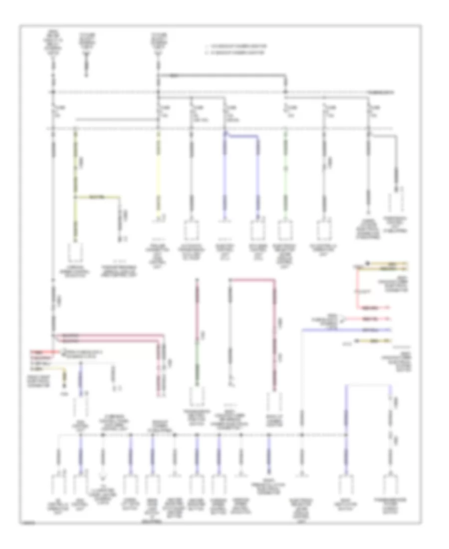
Power Distribution Wiring Diagram (5 of 6) for Mercedes-Benz Sprinter 2014 2500
List of elements for Power Distribution Wiring Diagram (5 of 6) for Mercedes-Benz Sprinter 2014 2500:
- 2.1l
- 28a
- 3.0l
- 30a
- 31b
- 32b
- 37a
- 37b
- 38b
- 39a
- 39b
- Ac control & operating unit
- Brake signal electrical connector
- Cdi control unit
- Circuit 15 relief relay 2
- Circuit 15 starter relay
- Circuit 15r relief relay
- Collision prevention assist control unit
- Diagnostic connector
- Driver door control panel
- Esp control unit (if equipped)
- From circuit 15 relay (diagram 2 of 6)
- From fuse & relay module (diagram 2 of 6)
- From fuse block 3 (diagram 4 of 6)
- From fuse block 4 (diagram 1 of 6)
- From fuse box (diagram 1 of 6)
- Fuse & relay module
- Fuse 10a
- Fuse 15a
- Fuse 25a
- Fuse 30a
- Fuse 5a
- Fuse block 3
- Fuse block 6
- Fuse block 7
- Headlamp range adjustment (hra (lwr)) control unit
- Heated rear window relay 2 (w/ anti-theft alarm system)
- Highline
- Highline air bag control unit
- Instrument cluster
- Left rear end door wiper motor
- Left rear radar sensor (w/ blind spot assist)
- Left side radar sensor (w/ blind spot assist)
- Left xenon lamp unit (if equipped)
- Light switch
- Lowline
- Multi-function camera (w/ lane keeping & highbeam assist)
- Rear heater/air conditioner air recirculation unit
- Red
- Right rear end door wiper motor
- Right rear radar sensor (w/ blind spot assist)
- Right side radar sensor (w/ blind spot assist)
- Right xenon lamp unit (if equipped)
- Roof ventilator switch
- Tone sequence relay
- W/o blind spot assist
- W71/1
- W71/2
- X18/53
- X18/77
- X18/82
- X35/1
- X8/21
- X8/23
- Yaw rate lateral & longitudinal acceleration sensor (if equipped)
Power Distribution Wiring Diagram (6 of 6) for Mercedes-Benz Sprinter 2014 2500
List of elements for Power Distribution Wiring Diagram (6 of 6) for Mercedes-Benz Sprinter 2014 2500:
- (2.1l)
- (or 10a) (or 5a)
- Boost pressure control flap pressure transducer (2.1l)
- Cdi control unit
- Circuit 87 engine control relay
- Coolant pump switchover valve (2.1l)
- Exhaust gas recirculation cooling solenoid valve
- Fan (3.0l)
- From fuse & relay module (diagram 3 of 6)
- From fuse 2 (diagram 3 of 6)
- Fuel pump relay (3.0l)
- Fuse & relay module
- Fuse 10a
- Fuse 20a
- Fuse 25a
- Fuse 7.5a
- Fuse 7.5a (or 10a)
- Fuse block
- Intake port shutoff actuator (3.0l)
- Nca
- Nox sensor control unit downstream of scr catalytic converter
- Nox sensor control unit upstream of scr catalytic converter
- Oil spray nozzles valve (2.1l)
- Oxygen sensor
- Oxygen sensor (2.1l)
- Pressure regulator valve
- Quantity control valve
- Red
- Regulated oil pressure pump valve (2.1l)
- Soot particulate sensor
- Soot particulate sensor (3.0l)
- Vent line heater element (2.1l)
- Wastegate pressure transducer (2.1l)
- X26/61
POWER DOOR LOCKS
Power Door Locks Wiring Diagram for Mercedes-Benz Sprinter 2014 2500
List of elements for Power Door Locks Wiring Diagram for Mercedes-Benz Sprinter 2014 2500:
- 17b
- Can-b h
- Can-b l
- Computer data lines system
- Control unit
- Crewcab left door central locking actuator
- Crewcab right door central locking actuator
- Driver door central locking actuator
- Front passenger door central locking actuator
- Fuse 1 25a
- Fuse 10a
- Fuse block
- Fuse block 2
- Hot at all times
- Left front door
- Left sliding door central locking motor actuator
- Motion detector
- Rear end door central locking actuator
- Right sliding door central locking motor actuator
- Sam control unit
- W43/1
- W71/1
- X100/19
- X100/21
- X18/52
- X18/75
- X35/108
- X35/109
- X35/2
- X35/41
- X43/11
- X43/12
- X8/20
POWER MIRRORS
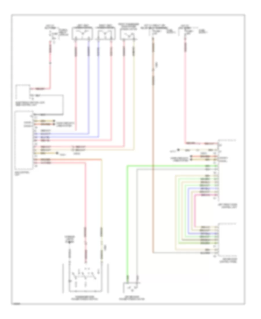
Power Mirrors Wiring Diagram for Mercedes-Benz Sprinter 2014 2500
List of elements for Power Mirrors Wiring Diagram for Mercedes-Benz Sprinter 2014 2500:
- Can-b h
- Can-b l
- Computer data lines system
- Driver door control panel
- Driver side outside mirror
- Fuse 1 5a
- Fuse block 3
- Hot w/ circuit 15r relief relay energized
- Left front door control unit
- Parktronic control unit
- Parktronic warning buzzer
- Passenger side outside mirror
- Sam control unit
- W/ blind spot assist
- W43/1
- X35/1
- X35/112
- X35/43
POWER SEATS
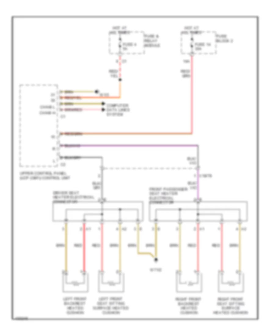
Power Seats Wiring Diagram for Mercedes-Benz Sprinter 2014 2500
List of elements for Power Seats Wiring Diagram for Mercedes-Benz Sprinter 2014 2500:
- 14a
- Can-b h
- Can-b l
- Computer data lines system
- Driver seat heater electrical connector
- Front passenger seat heater electrical connector
- Fuse & relay module
- Fuse 14 30a
- Fuse 4 5a
- Fuse block 2
- Hot at all times
- Left front backrest heated cushion
- Left front seat sitting surface heated cushion
- Red
- Right front backrest heated cushion
- Right front seat sitting surface heated cushion
- Upper control panel (ucp (obf)) control unit
- W1/3
- W71/2
- X18/78
POWER TOP/SUNROOF
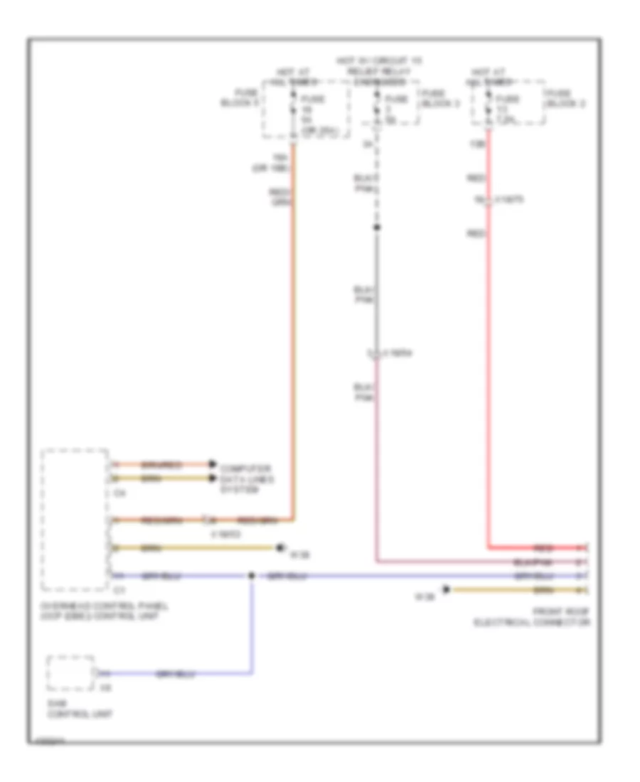
Power Top/Sunroof Wiring Diagram for Mercedes-Benz Sprinter 2014 2500
List of elements for Power Top/Sunroof Wiring Diagram for Mercedes-Benz Sprinter 2014 2500:
- 13b
- 19a (or 19b)
- Computer data lines system
- Front roof electrical connector
- Fuse 5a
- Fuse 5a (or 25a)
- Fuse 7.5a
- Fuse block 2
- Fuse block 3
- Fuse block 5
- Hot at all times
- Hot w/ circuit 15 relief relay energized
- Overhead control panel (ocp (dbe)) control unit
- Red
- Sam control unit
- W38
- X18/53
- X18/54
- X18/75
POWER WINDOWS
Power Windows Wiring Diagram for Mercedes-Benz Sprinter 2014 2500
List of elements for Power Windows Wiring Diagram for Mercedes-Benz Sprinter 2014 2500:
- Can-b h
- Can-b l
- Computer data lines system
- Control unit
- Driver door control panel
- Driver door power window motor
- Electronic ignition lock (ezs) control unit
- Front passenger door power window motor
- Fuse & relay module
- Fuse 1 25a
- Fuse 1 5a
- Fuse 25a
- Fuse block 1
- Fuse block 3
- Hot at all times
- Hot w/ circuit 15r relief relay energized
- Interior lights system
- Left front door
- Left vent window motor
- Passenger side power window switch
- Right vent window motor
- Sam control unit
- W43/1
- W71/1
- X35/1
- X35/2
- X35/41
- X35/42
RADIO
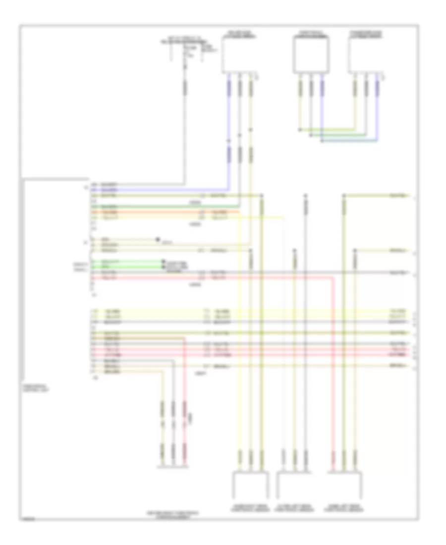
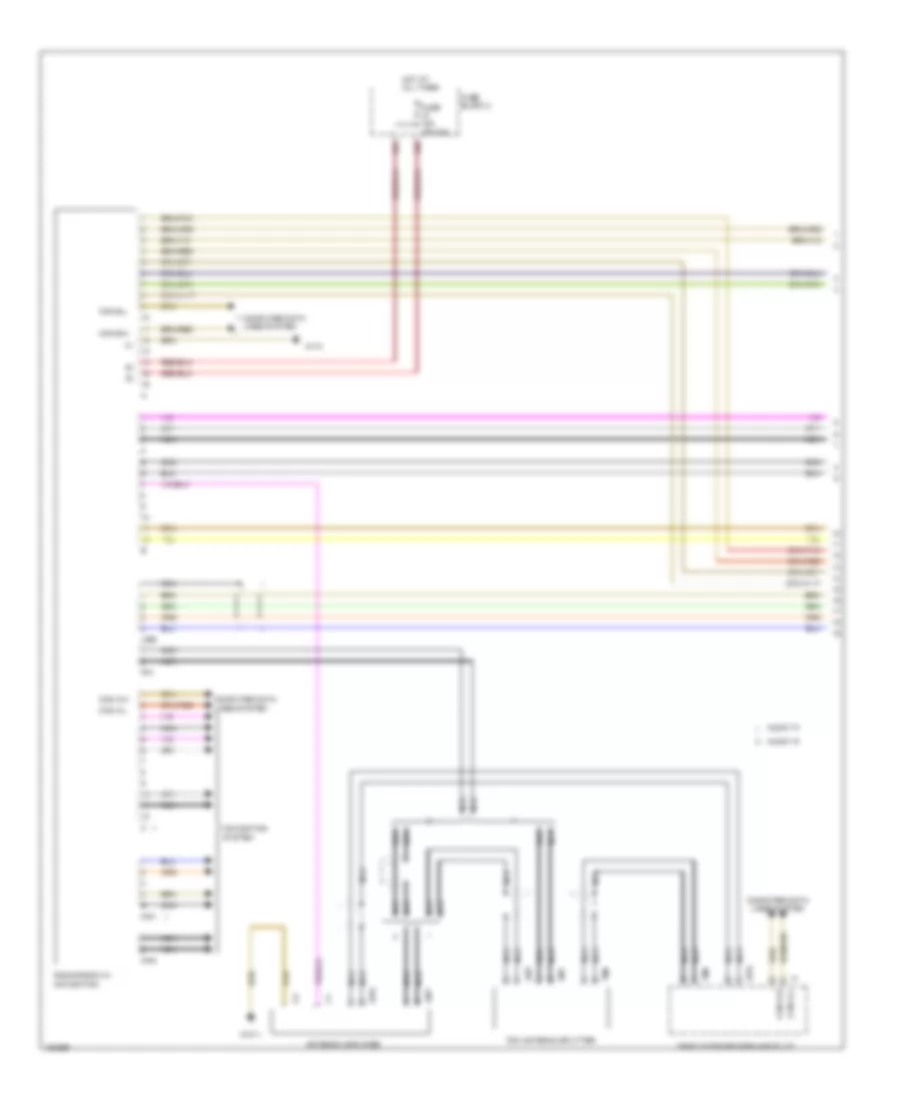
Radio Wiring Diagram, Except Pre-Installed (1 of 3) for Mercedes-Benz Sprinter 2014 2500
List of elements for Radio Wiring Diagram, Except Pre-Installed (1 of 3) for Mercedes-Benz Sprinter 2014 2500:
- 10a
- 10b
- Ant
- Antenna amplifier
- Audio 10
- Audio 15
- Cam
- Can a-h
- Can a-l
- Can b-h
- Can b-l
- Computer data lines system
- Cradle for becker map pilot
- Fm1
- Fuse 15a (or 20a)
- Fuse block 2
- Gps
- Hot at all times
- Nav
- Navigation system
- Nca
- Radio/radio w/ navigation
- Tmc
- Tmc antenna splitter
- Usb
- W1/3
- W31/1
Radio Wiring Diagram, Except Pre-Installed (2 of 3) for Mercedes-Benz Sprinter 2014 2500
List of elements for Radio Wiring Diagram, Except Pre-Installed (2 of 3) for Mercedes-Benz Sprinter 2014 2500:
- Hands-free system microphone
- Left rear end bass & midrange speaker (minibus)
- Left rear end tweeter (minibus)
- Left rear side wall speaker
- Left rear side wall tweeter
- Nca
- Right rear end bass & midrange speaker (minibus)
- Right rear end tweeter (minibus)
- Right rear side wall speaker
- Right rear side wall tweeter
- Usb/aux interface
- X18/23
- X18/64
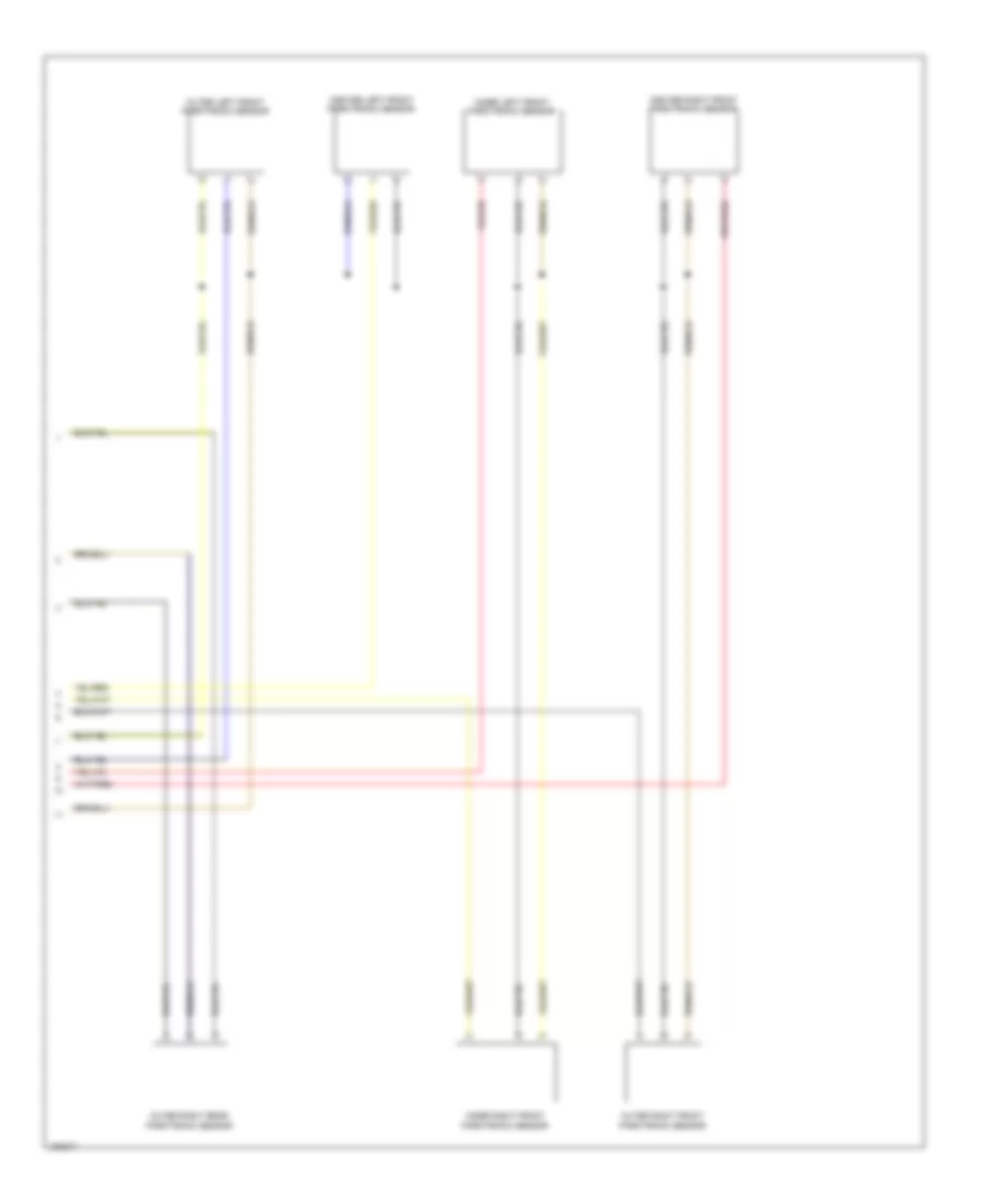
Radio Wiring Diagram, Except Pre-Installed (3 of 3) for Mercedes-Benz Sprinter 2014 2500
List of elements for Radio Wiring Diagram, Except Pre-Installed (3 of 3) for Mercedes-Benz Sprinter 2014 2500:
- (or 5)
- (or 6)
- (or x35/108) x100/16
- (or x35/109) x100/14
- Center front speaker
- Door tweeter
- Left bass midrange speaker
- Left front
- Left side wall bass midrange speaker (minibus)
- Left side wall tweeter (minibus)
- Left sliding door bass midrange speaker
- Left sliding door tweeter
- Right bass midrange
- Right front
- Right side wall bass midrange speaker (minibus)
- Right side wall tweeter (minibus)
- Right sliding door bass midrange speaker
- Right sliding door tweeter
- Speaker
- W/ door tweeter
- W/ midrange speaker
- X100/2 (or x100/19)
- X100/4 (or x100/21)
- X18/49
- X18/79
- X35/41
- X35/42
Radio Wiring Diagram, Pre-Installed (1 of 2) for Mercedes-Benz Sprinter 2014 2500
List of elements for Radio Wiring Diagram, Pre-Installed (1 of 2) for Mercedes-Benz Sprinter 2014 2500:
- 10a
- Backup camera monitor
- Fuse & relay module
- Fuse 15a
- Fuse 15a (or 20a)
- Fuse block 2
- Hot at all times
- Hot w/ circuit 15r relay energized
- Instrument cluster
- Interior lights system
- Left rear end bass & midrange speaker (minibus)
- Left rear end tweeter (minibus)
- Left rear side wall speaker
- Left rear side wall tweeter
- Radio preinstallation electrical connector
- Right rear end bass & midrange speaker (minibus)
- Right rear end tweeter (minibus)
- Right rear side wall speaker
- Right rear side wall tweeter
- W/ backup camera monitor
- W/o backup camera monitor
- W1/3
- X170
- X18/23
- X18/64
Radio Wiring Diagram, Pre-Installed (2 of 2) for Mercedes-Benz Sprinter 2014 2500
List of elements for Radio Wiring Diagram, Pre-Installed (2 of 2) for Mercedes-Benz Sprinter 2014 2500:
- (or 5)
- (or 6)
- (or x35/108) x100/16
- (or x35/109) x100/14
- Center front speaker
- Door tweeter
- Left bass midrange speaker
- Left front
- Left side wall bass midrange speaker (minibus)
- Left side wall tweeter (minibus)
- Left sliding door bass midrange speaker
- Left sliding door tweeter
- Right bass midrange
- Right front
- Right side wall bass midrange speaker (minibus)
- Right side wall tweeter (minibus)
- Right sliding door bass midrange speaker
- Right sliding door tweeter
- Speaker
- W/ door tweeter
- W/ midrange speaker
- X100/2 (or x100/19)
- X100/4 (or x100/21)
- X18/49
- X18/79
- X35/41
- X35/42
SHIFT INTERLOCK
Shift Interlock Wiring Diagram for Mercedes-Benz Sprinter 2014 2500
List of elements for Shift Interlock Wiring Diagram for Mercedes-Benz Sprinter 2014 2500:
- Can b h
- Can b l
- Can c h
- Can c l
- Computer data lines system
- Electric control unit
- Electronic ignition lock (ezs) control unit
- Electronic selector lever module control unit
- Esp control unit
- Etc (egs) control unit
- Fuse & relay module
- Fuse 10a
- Fuse block 3
- Hot w/ circuit 15 relief relay energized
- Sam control module
- Stop lamp switch
- W1/3
- X18/56
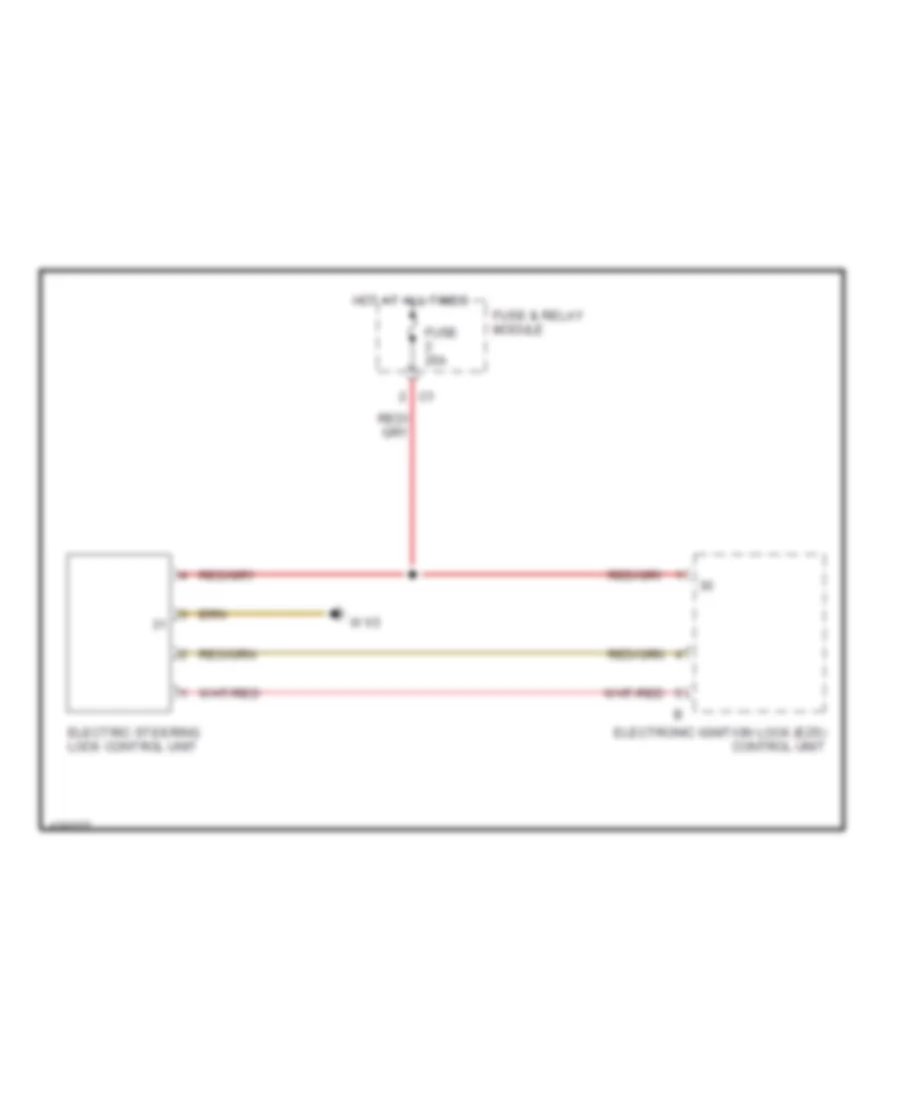
Steering Column Wiring Diagram for Mercedes-Benz Sprinter 2014 2500
List of elements for Steering Column Wiring Diagram for Mercedes-Benz Sprinter 2014 2500:
- Electric steering lock control unit
- Electronic ignition lock (ezs) control unit
- Fuse & relay module
- Fuse 25a
- Hot at all times
- W1/3
STARTING/CHARGING
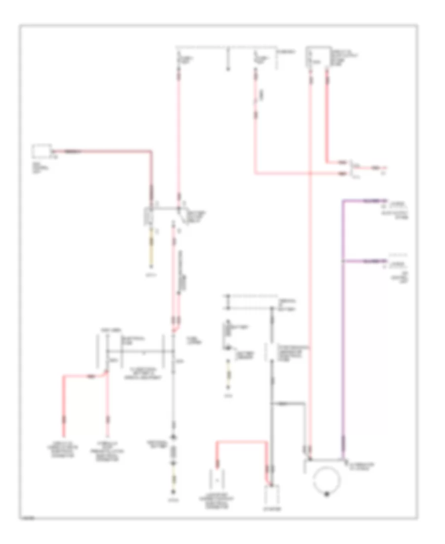
Charging Wiring Diagram for Mercedes-Benz Sprinter 2014 2500
List of elements for Charging Wiring Diagram for Mercedes-Benz Sprinter 2014 2500:
- (not used)
- 100a
- 2.1l
- 250a
- 3.0l
- Additional battery
- Alternator w/ lin bus
- Battery
- Battery cutoff relay
- Battery sensor
- Cdi control unit
- Circuit 30 cargo liftgate electrical connector
- Circuit 30 glow output stage fuse
- Electrical fuse
- Fuse 1 80a
- Fuse 4 150a
- Fuse box
- Fuse/ jumper
- Glow output stage
- Hydraulic pump preinstallation electrical connector
- Jump-start connection point electrical connector
- Lin
- Lin bus
- Pyrotechnical separator electrical fuse
- Red
- Sam control uniy
- Starter
- System power distribution
- Terminal battery
- W/ additional battery & special equipment
- W10
- W10/4
- W71/1
- X26/64
Starting Wiring Diagram for Mercedes-Benz Sprinter 2014 2500
List of elements for Starting Wiring Diagram for Mercedes-Benz Sprinter 2014 2500:
- 2.1l
- 28a
- 3.0l
- Batt sens
- Battery sensor
- Can-b h
- Can-b l
- Can-c h
- Can-c l
- Cdi control unit
- Charging circuit
- Circuit 15 starter relay
- Circuit 30 jumper
- Circuit 50 starter relay
- Circuit battery
- Computer data lines system
- Electric control unit
- Electronic ignition lock (ezs) control unit
- Etc (egs) control unit (3.0l)
- Fuse & relay module
- Fuse 10a
- Fuse 25a
- Fuse block 6
- Fuse box
- Hot at all times
- Hot w/ circuit 15 relay energized
- Jump-start connection point electrical connector
- On-board electrical system battery
- Pyrotechnical separator electrical fuse
- Red
- Sam control unit
- Starter
- Starter lockout contact
- W10
- X26/61
- X26/65
SUPPLEMENTAL RESTRAINTS
Supplemental Restraints Wiring Diagram (1 of 2) for Mercedes-Benz Sprinter 2014 2500
List of elements for Supplemental Restraints Wiring Diagram (1 of 2) for Mercedes-Benz Sprinter 2014 2500:
- 15r
- Can-b h
- Can-b l
- Center front passenger emergency tensioning retractor squib
- Computer data lines system
- Driver etr (gus) squib
- Driver seat belt buckle switch
- Front passenger etr (gus) squib
- Fuse & relay module
- Fuse 10a
- Fuse 5a
- Highline air bag control unit
- Hot w/ circuit 15 relay energized
- Hot w/ circuit 15r relay energized
- Left side bag sensor
- Left window bag squib
- Right side bag sensor
- W26
- W43/1
- W71/1
- X28/40
- X55/32
Supplemental Restraints Wiring Diagram (2 of 2) for Mercedes-Benz Sprinter 2014 2500
List of elements for Supplemental Restraints Wiring Diagram (2 of 2) for Mercedes-Benz Sprinter 2014 2500:
- 15r
- Air bag system driver door pressure sensor
- Air bag system front passenger door pressure sensor
- Cab-b h
- Cab-b l
- Can-c h
- Can-c l
- Computer data lines system
- Driver air bag squib
- Driver head/thorax side bag squib
- Front passenger head/thorax side bag squib
- Gnd
- Highline air bag control unit
- Instrument cluster
- Pyrofuse
- Right window bag squib
- Steering column tube module (mrm) control unit
- W1/3
- W1/4
- W26
- W71/1
- X28/29
- X28/30
- X28/46
- X35/110
- X35/44
TRANSMISSION
2.1L
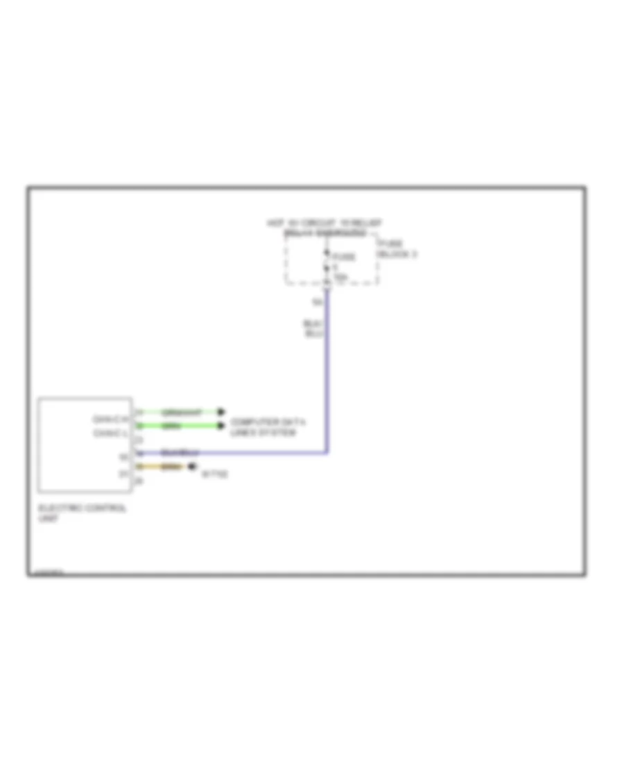
2.1L, Transmission Wiring Diagram for Mercedes-Benz Sprinter 2014 2500
List of elements for 2.1L, Transmission Wiring Diagram for Mercedes-Benz Sprinter 2014 2500:
- Can-c h
- Can-c l
- Computer data lines system
- Electric control unit
- Fuse 10a
- Fuse block 3
- Hot w/ circuit 15 relief relay energized
- W71/2
3.0L
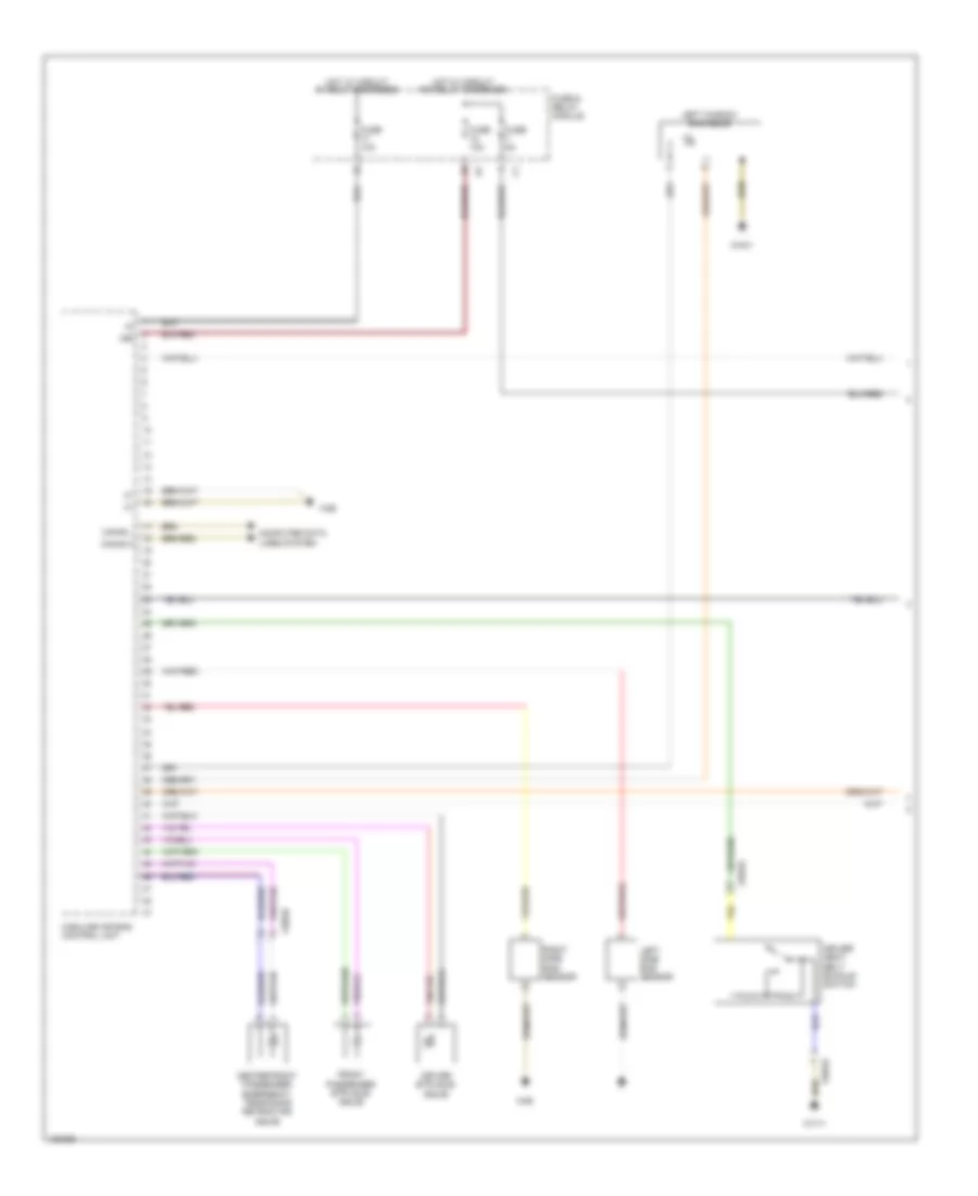
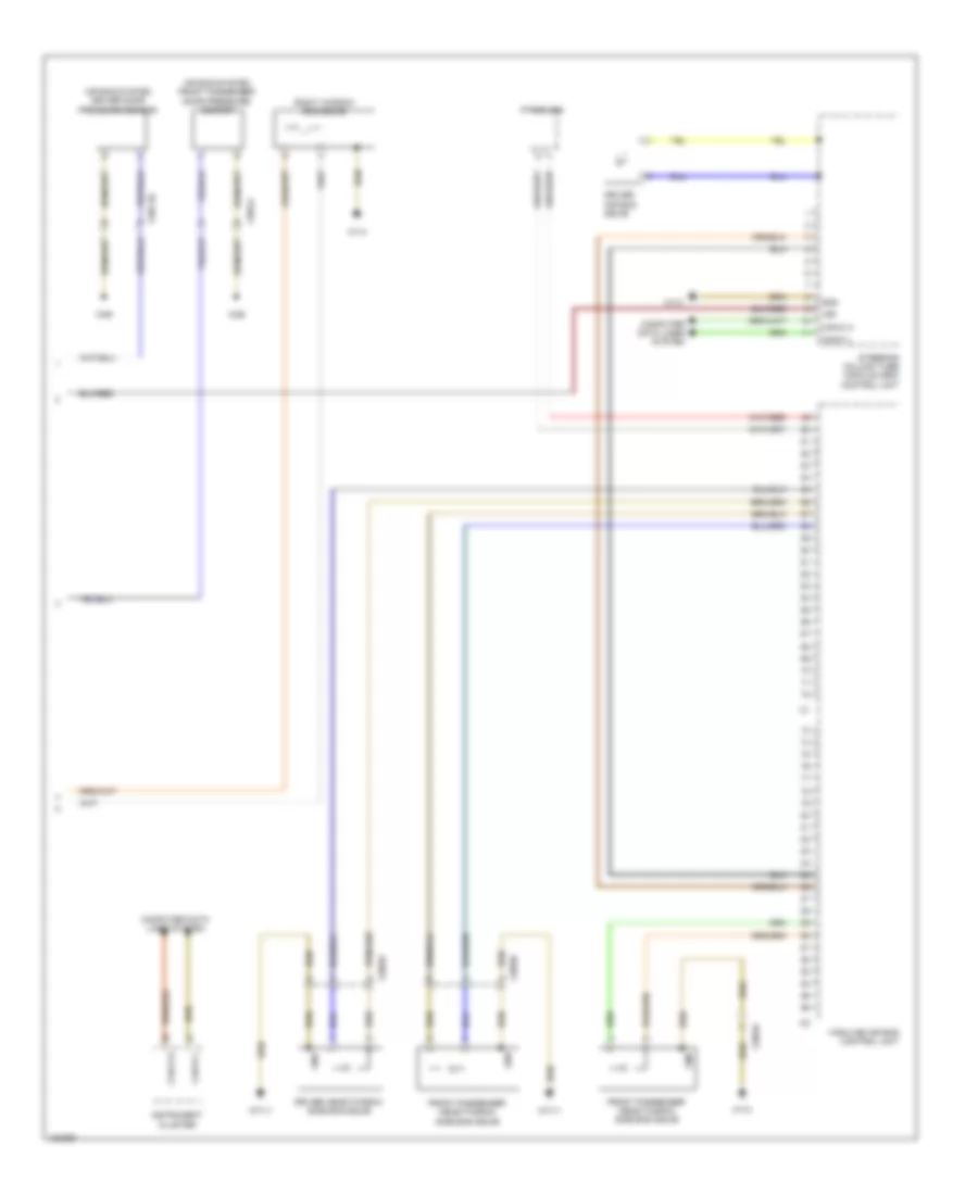
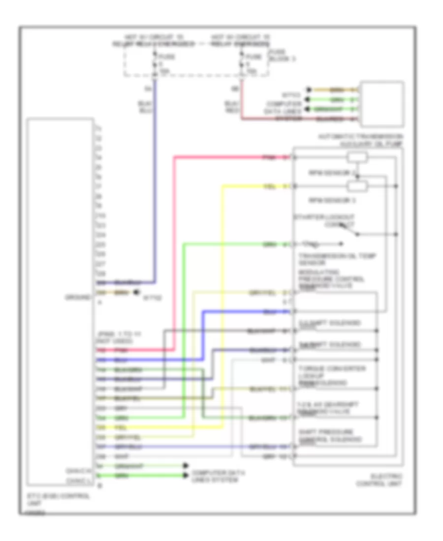
3.0L, Transmission Wiring Diagram for Mercedes-Benz Sprinter 2014 2500
List of elements for 3.0L, Transmission Wiring Diagram for Mercedes-Benz Sprinter 2014 2500:
- (pins: 1 to 11 not used)
- 1-2 & 4-5 gearshift solenoid valve
- 2-3 shift solenoid
- 3-4 shift solenoid
- Automatic transmission auxiliary oil pump
- Can-c h
- Can-c l
- Computer data lines system
- Electric control unit
- Etc (egs) control unit
- Fuse 10a
- Fuse block 3
- Ground
- Hot w/ circuit 15 relay energized
- Hot w/ circuit 15 relief relay energized
- Modulating pressure control solenoid valve
- Pnk
- Rpm sensor 2
- Rpm sensor 3
- Shift pressure control solenoid
- Starter lockout contact
- Torque converter lockup pwm solenoid
- Transmission oil temp sensor
- W71/2
- W71/3
TRUNK, TAILGATE, FUEL DOOR
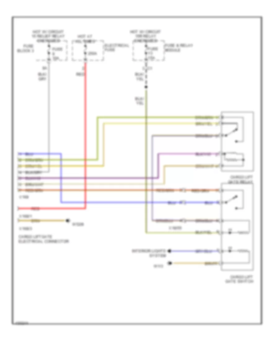
Liftgate Wiring Diagram for Mercedes-Benz Sprinter 2014 2500
List of elements for Liftgate Wiring Diagram for Mercedes-Benz Sprinter 2014 2500:
- 250a
- All times
- Cargo lift gate relay
- Cargo lift gate switch
- Cargo liftgate electrical connector
- Electrical fuse
- Fuse & relay module
- Fuse 10a
- Fuse 15a
- Fuse block 3
- Hot at
- Hot w/ circuit 15 relief relay energized
- Hot w/ circuit 15r relay energized
- Interior lights system
- Red
- W1/3
- W52/8
- X168
- X168/1
- X168/3
- X18/55
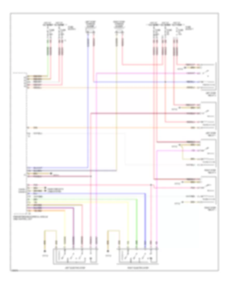
Power Sliding Door Wiring Diagram for Mercedes-Benz Sprinter 2014 2500
List of elements for Power Sliding Door Wiring Diagram for Mercedes-Benz Sprinter 2014 2500:
- 17a
- 17b
- 18a
- 18b
- 43a
- 43b
- 44a
- 44b
- 45a
- 45b
- Can-b h
- Can-b l
- Computer data lines system
- Fuse 10a
- Fuse 25a
- Fuse 5a
- Fuse block 4
- Fuse block 7
- Hot at all times
- Left electric step
- Left step relay 1
- Left step relay 2
- Left step warning buzzer
- Parameterizable special module (psm) control unit
- Pnk
- Right electric step
- Right step relay 1
- Right step relay 2
- Right step warning buzzer
- W71/1
- W71/2
WARNING SYSTEMS
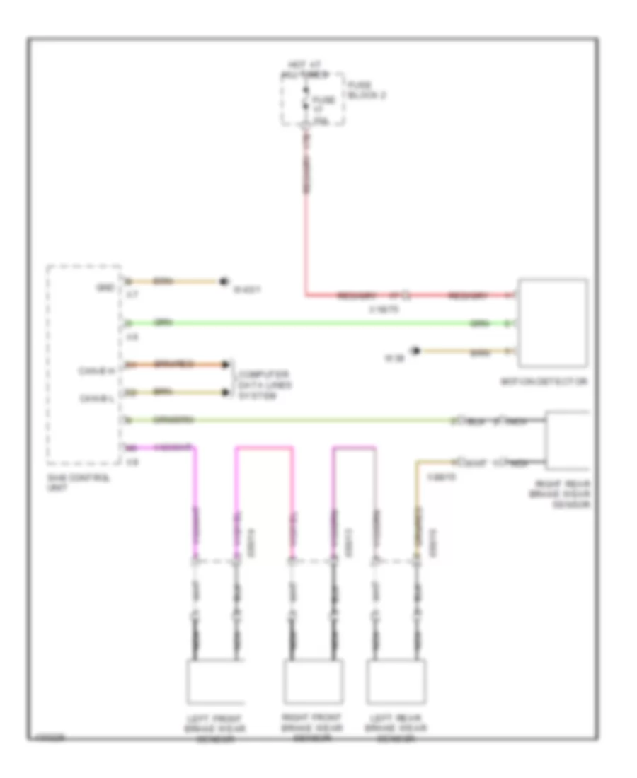
Brake Wear Sensor Wiring Diagram for Mercedes-Benz Sprinter 2014 2500
List of elements for Brake Wear Sensor Wiring Diagram for Mercedes-Benz Sprinter 2014 2500:
- 17b
- Can-b h
- Can-b l
- Computer data lines system
- Fuse 10a
- Fuse block 2
- Gnd
- Hot at all times
- Left front brake wear sensor
- Left rear brake wear sensor
- Motion detector
- Nca
- Right front brake wear sensor
- Right rear brake wear sensor
- Sam control unit
- W38
- W43/1
- X18/75
- X88/13
- X88/14
- X88/15
- X88/16
Chime Wiring Diagram for Mercedes-Benz Sprinter 2014 2500
List of elements for Chime Wiring Diagram for Mercedes-Benz Sprinter 2014 2500:
- 17b
- Block 2
- Brake fluid level switch
- Can-b h
- Can-b l
- Computer data lines system
- Crewcab left door central locking actuator
- Crewcab right door central locking actuator
- Door locks system
- Driver door central locking actuator
- Driver door control unit
- Driver seat belt buckle switch
- Front passenger door central locking actuator
- Fuse
- Fuse & relay
- Fuse 10a
- High line air bag control unit
- Hot at all times
- Instrument cluster
- Left sliding door central locking motor actuator
- Module
- Motion detector
- Parking brake indicator switch
- Rear-end door central locking actuator
- Right sliding door central locking motor actuator
- Sam control unit
- W/ sliding door
- W/o sliding door
- W1/3
- W38
- W43/1
- W71/1
- X100/19
- X100/21
- X18/52
- X18/75
- X35/108
- X35/109
- X35/2
- X43/11
- X43/12
- X8/20
Tire Pressure Monitoring Wiring Diagram for Mercedes-Benz Sprinter 2014 2500
List of elements for Tire Pressure Monitoring Wiring Diagram for Mercedes-Benz Sprinter 2014 2500:
- 16b
- Can-b h
- Can-b l
- Computer data lines system
- Fuse 7.5a
- Fuse block 4
- Hot at all times
- Monitor (rdk) control unit
- Rear tire pressure monitor decoder antenna
- Tire pressure
- W71/3
WIPER/WASHER
Front Wiper/Washer Wiring Diagram for Mercedes-Benz Sprinter 2014 2500
List of elements for Front Wiper/Washer Wiring Diagram for Mercedes-Benz Sprinter 2014 2500:
- 87a
- Can-b h
- Can-b l
- Computer data lines system
- Fuse & relay module
- Fuse 30a
- Hot at all times
- Overhead control panel (ocp (dbe)) control unit
- Rain/light sensor
- Sam control unit
- Stage 1 front windshield wiper relay
- Stage 2 front windshield wiper relay
- W9/7
- Windshield washer system pump
- Windshield washer system water level indicator switch
- Wiper motor
Headlamp Washer Wiring Diagram for Mercedes-Benz Sprinter 2014 2500
List of elements for Headlamp Washer Wiring Diagram for Mercedes-Benz Sprinter 2014 2500:
- (not used)
- Can-b h
- Can-b l
- Computer data lines system
- Fuse 7 30a
- Fuse block 1
- Headlamp cleaning system pump
- Headlamp cleaning system relay
- Hot at all times
- Sam control unit
- W71/1
- W9/7
Rear Wiper/Washer Wiring Diagram for Mercedes-Benz Sprinter 2014 2500
List of elements for Rear Wiper/Washer Wiring Diagram for Mercedes-Benz Sprinter 2014 2500:
- Can-b h
- Can-b l
- Computer data lines system
- Fuse 2 30a
- Fuse block 3
- Hot w/ circuit 15r relief relay energized
- Left rear end door wiper motor
- Rear end washer fluid pump
- Right rear end door wiper motor
- Sam control unit
- W29/8
- W9/7
- X18/53
- X8/21
- X8/22
- X8/23

 Čeština
 Dansk
Dansk Deutsch
 Ελληνικά
 English
 English
 Español
 Suomi
Suomi Français
 Français
 עברית
עברית Magyar
 Italiano
 日本語
日本語 한국어
한국어 Nederlands
 Polski
 Português
 Português
 Română
 Русский
 Slovenčina
 Slovenščina
 Svenska
 Türkçe
 中文 (中国)