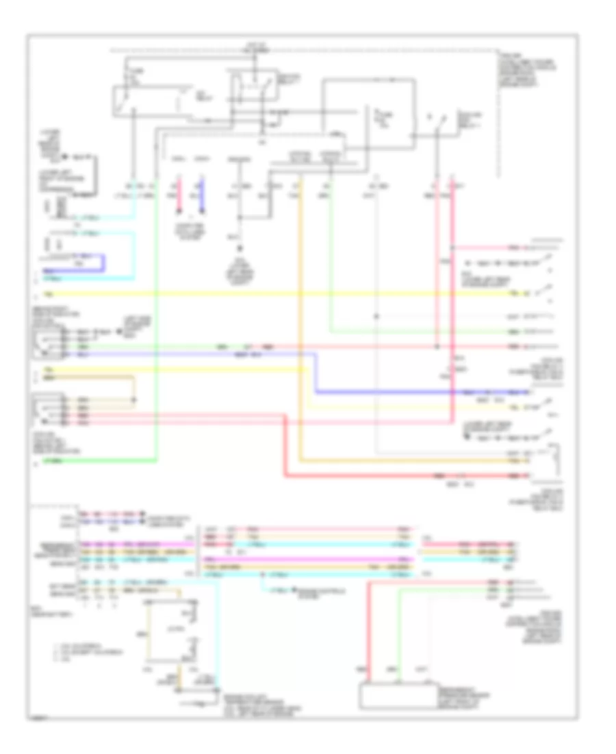
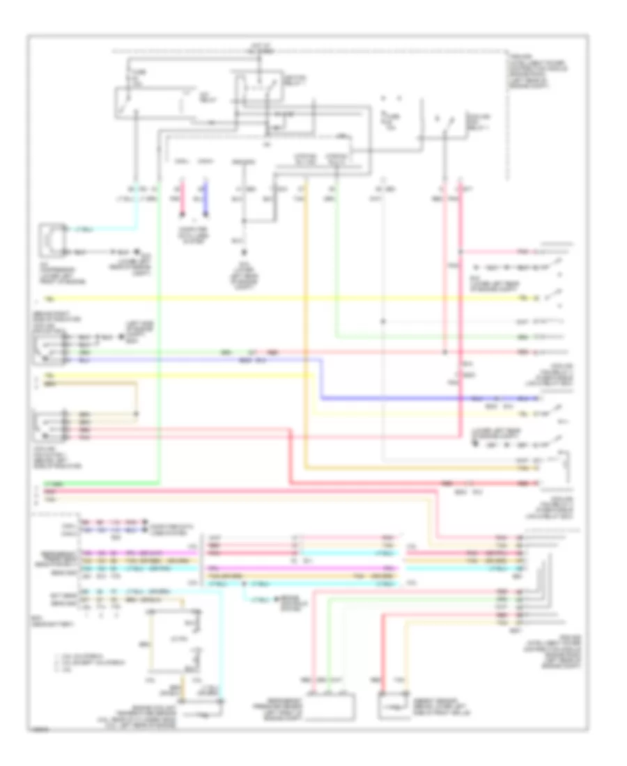
AIR CONDITIONING
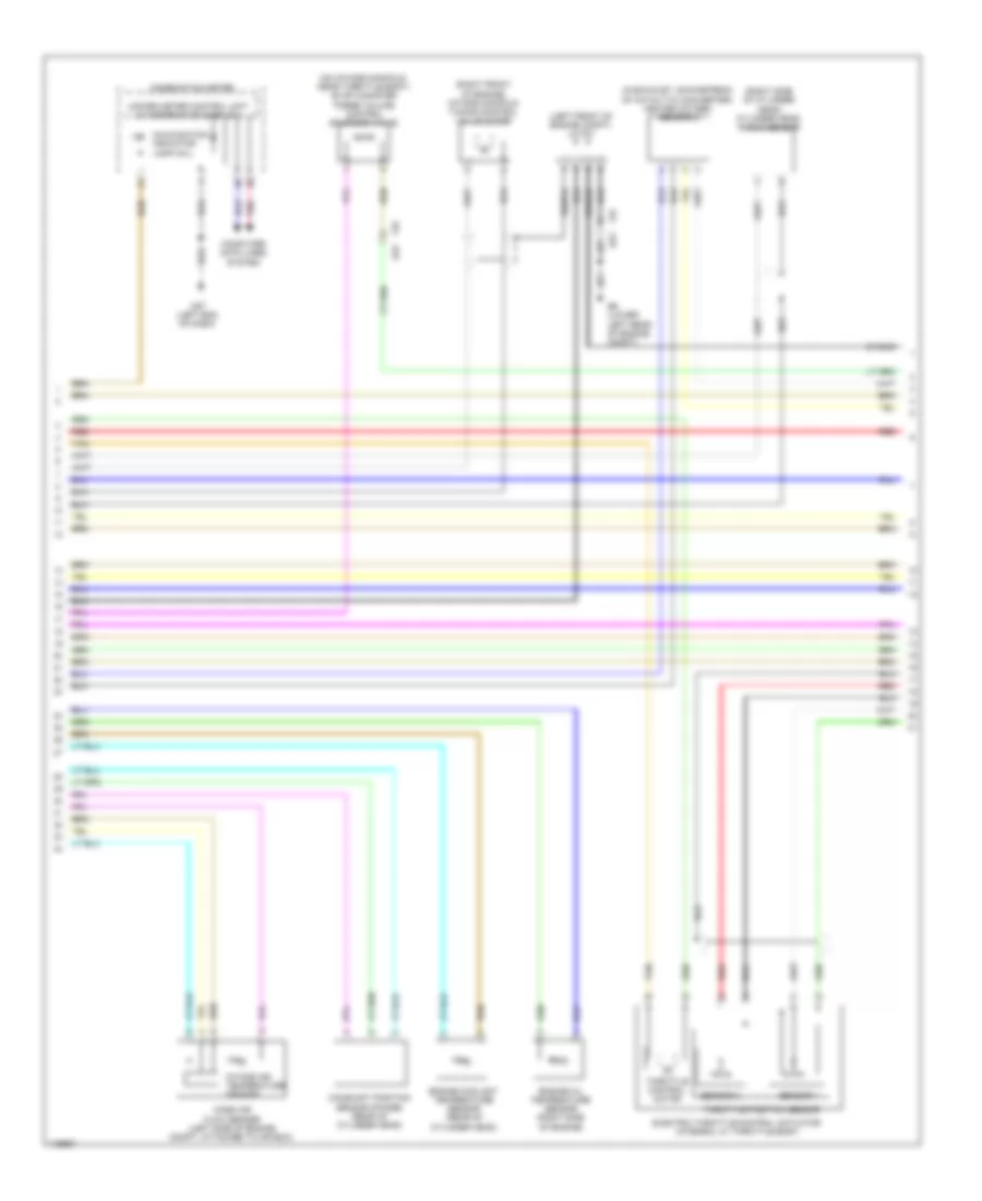
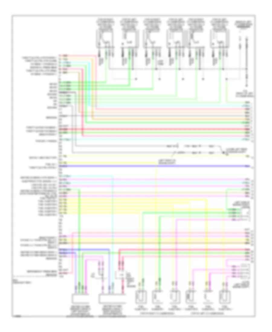
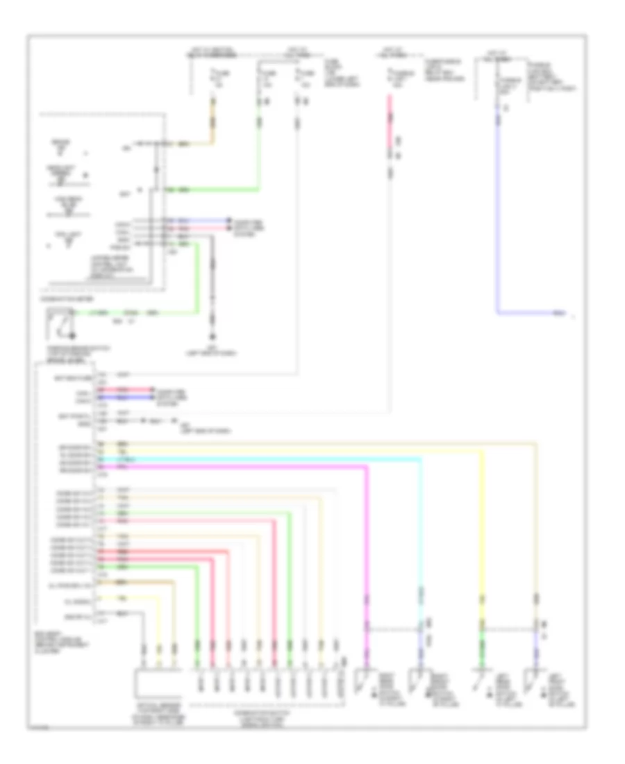
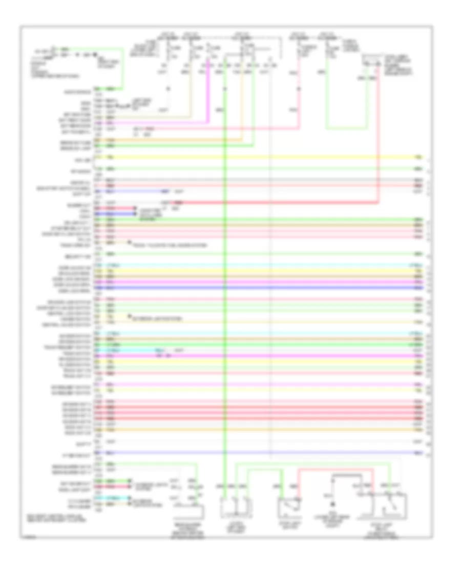
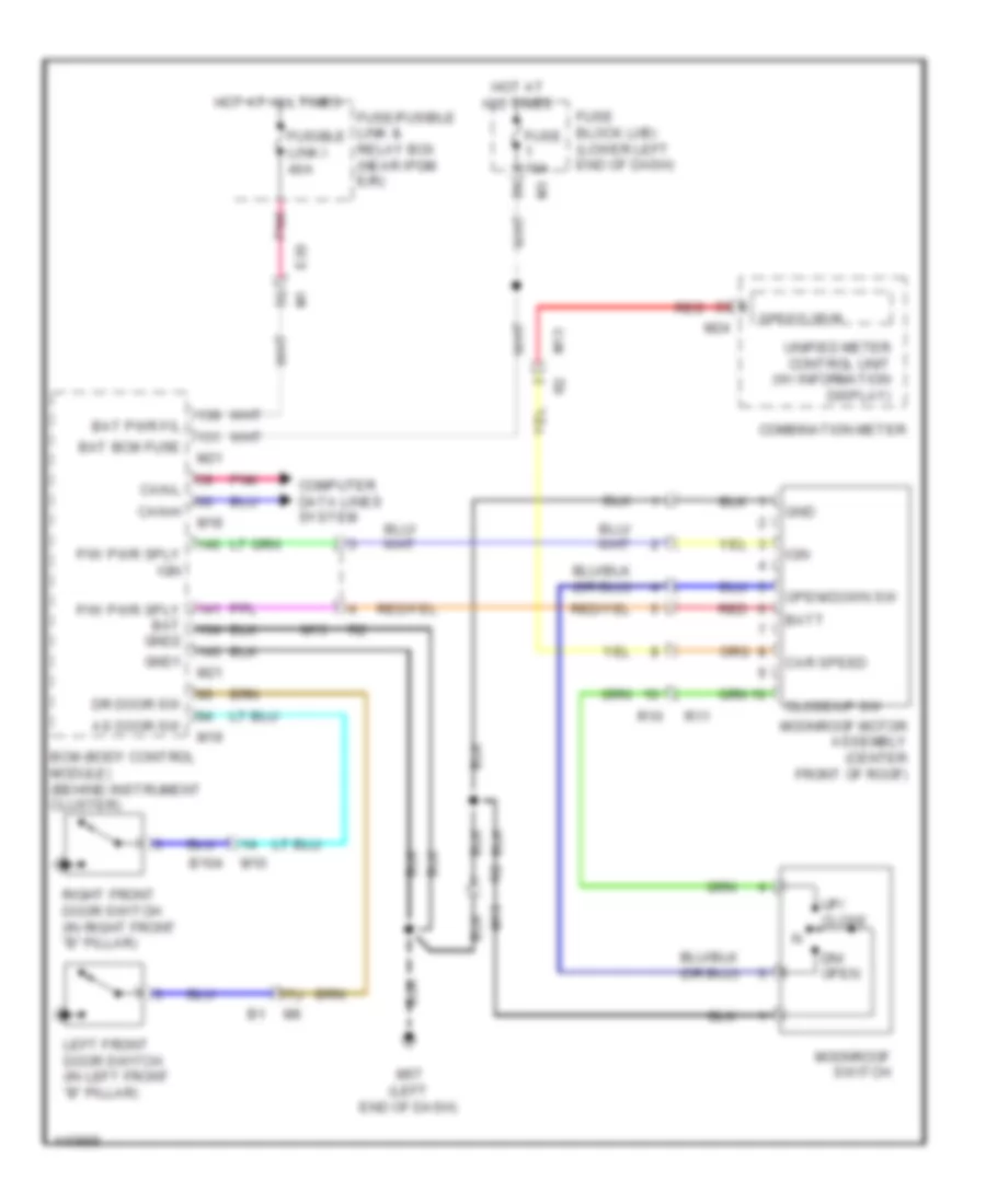
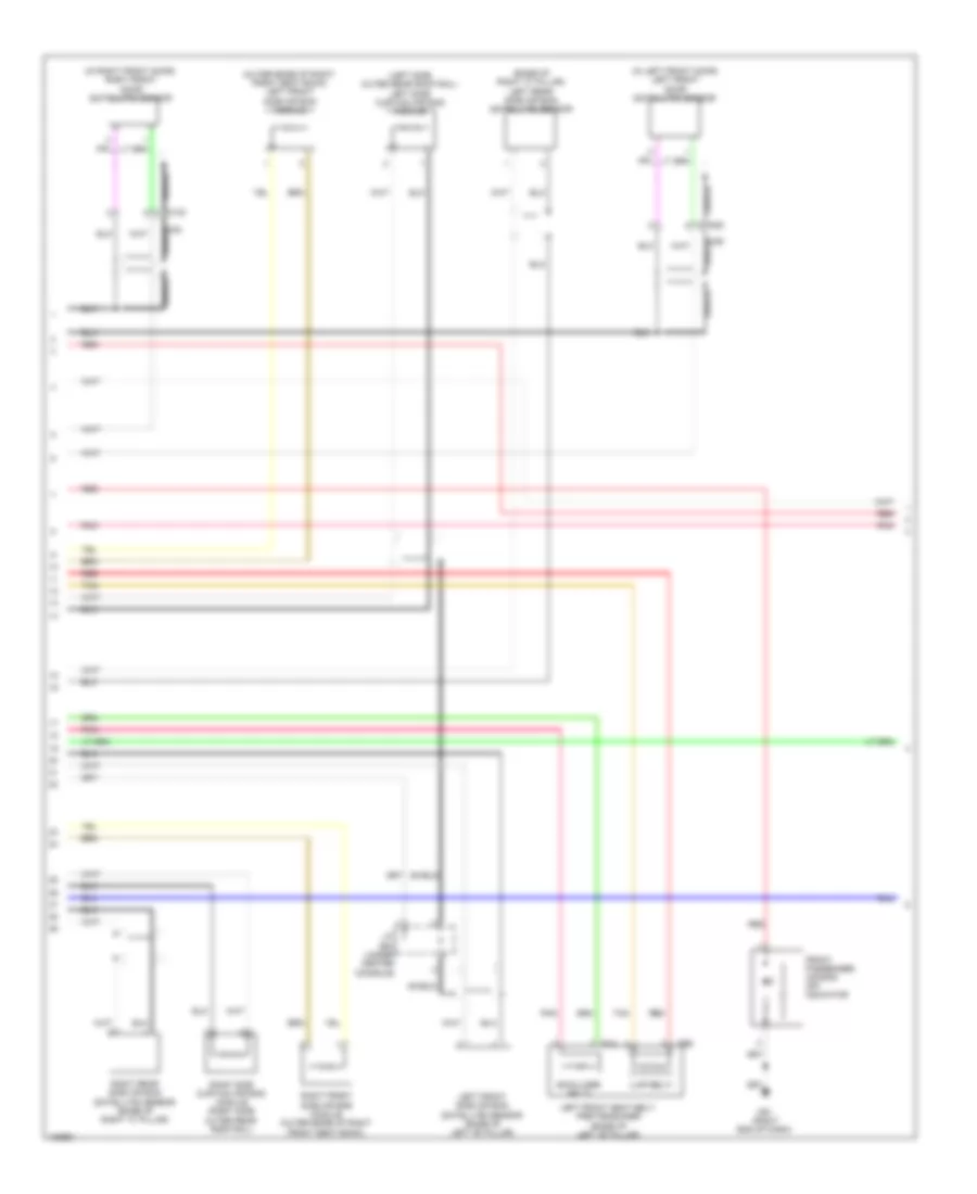
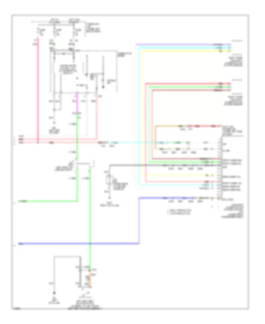
Automatic A/C Wiring Diagram (1 of 2) for Nissan Altima S 2014
 https://portal-diagnostov.com/license.html
Automotive Electricians Portal FZCO
Automotive Electricians Portal FZCO
https://portal-diagnostov.com/license.html
https://portal-diagnostov.com/license.html
Automotive Electricians Portal FZCO
Automotive Electricians Portal FZCO
List of elements for Automatic A/C Wiring Diagram (1 of 2) for Nissan Altima S 2014:
- (or pnk)
- (right end of dash) m61
- 13r m4
- 16p m5
- 17g
- 1m e6
- 2n m3
- 33g
- 34g
- 36g
- 3n m3
- 3r m4
- 7p m5
- A/c auto amplifier (behind a/c switch assembly)
- A/c switch assembly
- Acc rly out
- Accessory relay-2 (left end of dash)
- Actr (lin)
- Actr gnd
- Amb sens
- Ambient sensor (behind lower left side of front grille)
- Batt
- Blower motor (right side of hvac unit)
- Body control module (bcm) (behind instrument cluster)
- Can-h
- Can-l
- Can-l bwr fan rly out
- Computer data lines system
- Defogger system
- E1 1s
- E11
- E12
- E201
- E203
- E30
- E62
- E63
- Ecv out
- F2 e11
- Fr fan pwm
- Front blower motor relay
- Fuse & fusible link box (near ipdm e/r)
- Fuse 10a
- Fuse 15a
- Fuse 5a
- Fuse block (j/b) (lower left end of dash)
- Fusible link box (battery) (on battery positive (+) post)
- Fusible link f 100a
- Fusible link l 40a
- Fusible link n 40a
- Gnd
- Hot at all times
- Hot in on or acc
- Hot in on or start
- Ign
- Ign usm out 1
- Ign2
- In-vehicle sensor (lower left center of dash)
- Inc sens
- Int sens
- Intake door motor (right side of blower housing)
- Intake sensor (lower right side hvac assembly)
- Interior lights system
- Ipdm e/r (intelligent power distribution module engine room) (left rear of engine compt)
- J/c e08 (left end of dash)
- Left air mix door motor (left side hvac unit)
- M1 e30
- M125
- M18
- M20
- M33
- M57 (left end of dash)
- M61 (right end of dash)
- Mode door motor (upper left side hvac unit)
- P gnd
- Pnk
- Red
- Right air mix door motor (right side hvac unit)
- Rr def f/b
- Rr def sw
- Rx fr
- Seats system
- Seats system computer data lines system
- Sens gnd
- Strg htr rly
- Strg htr sw
- Sun sens
- Sunload sensor (top left end of dash, near left "a" pillar)
- Tan
- Tx fr
- Vactr
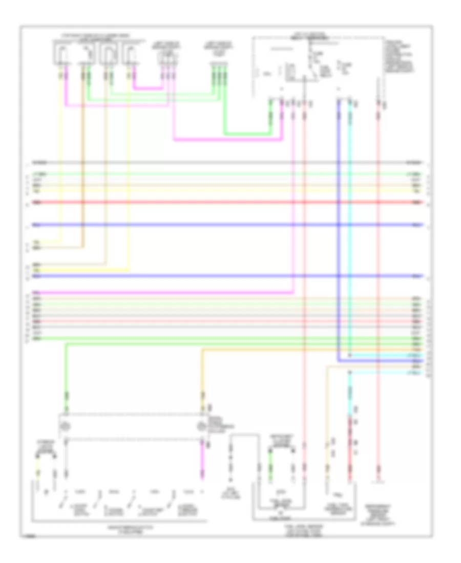
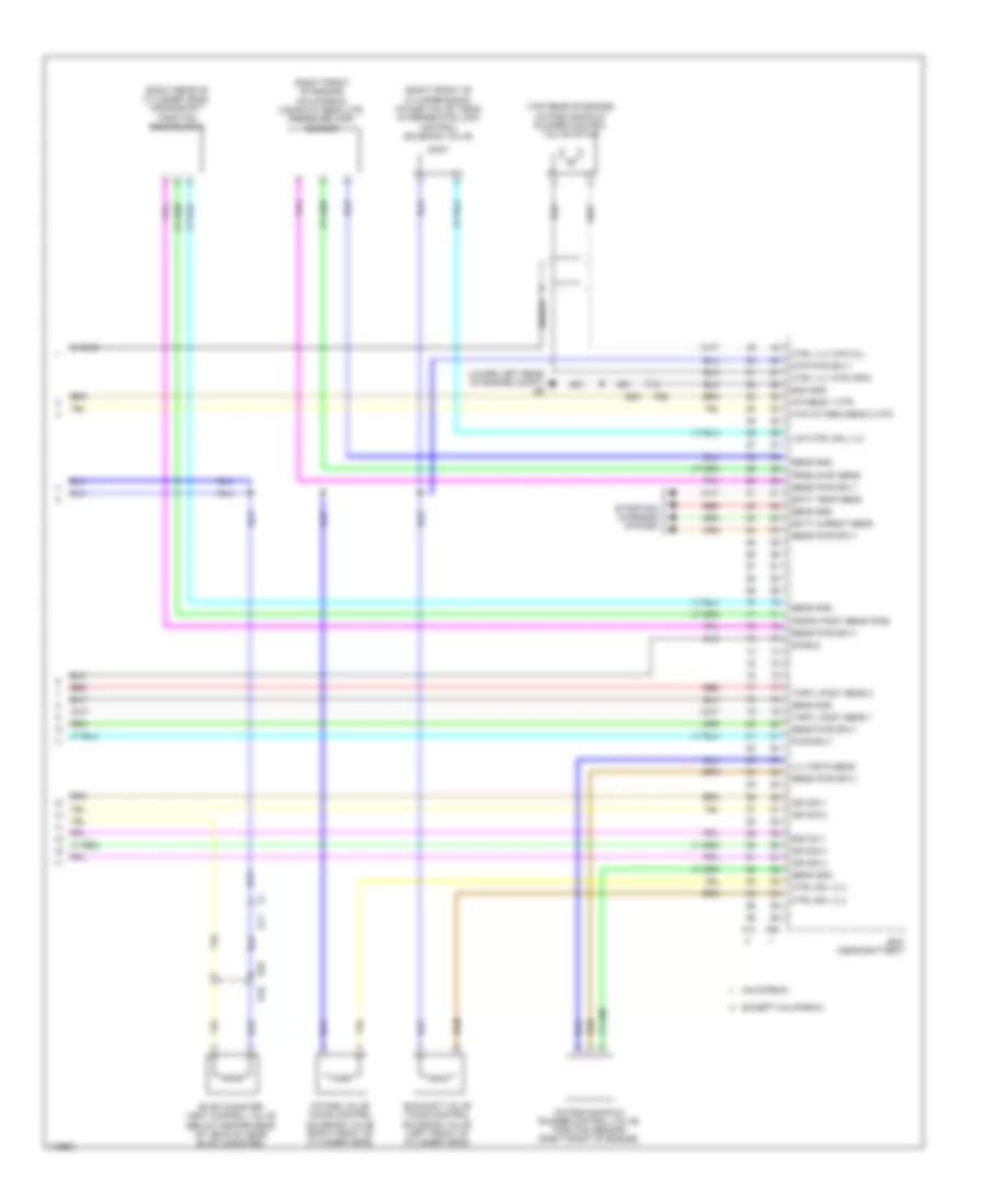
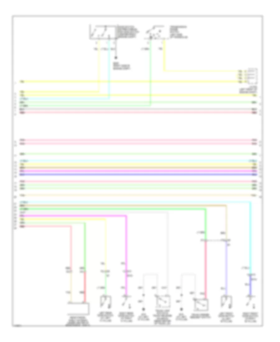
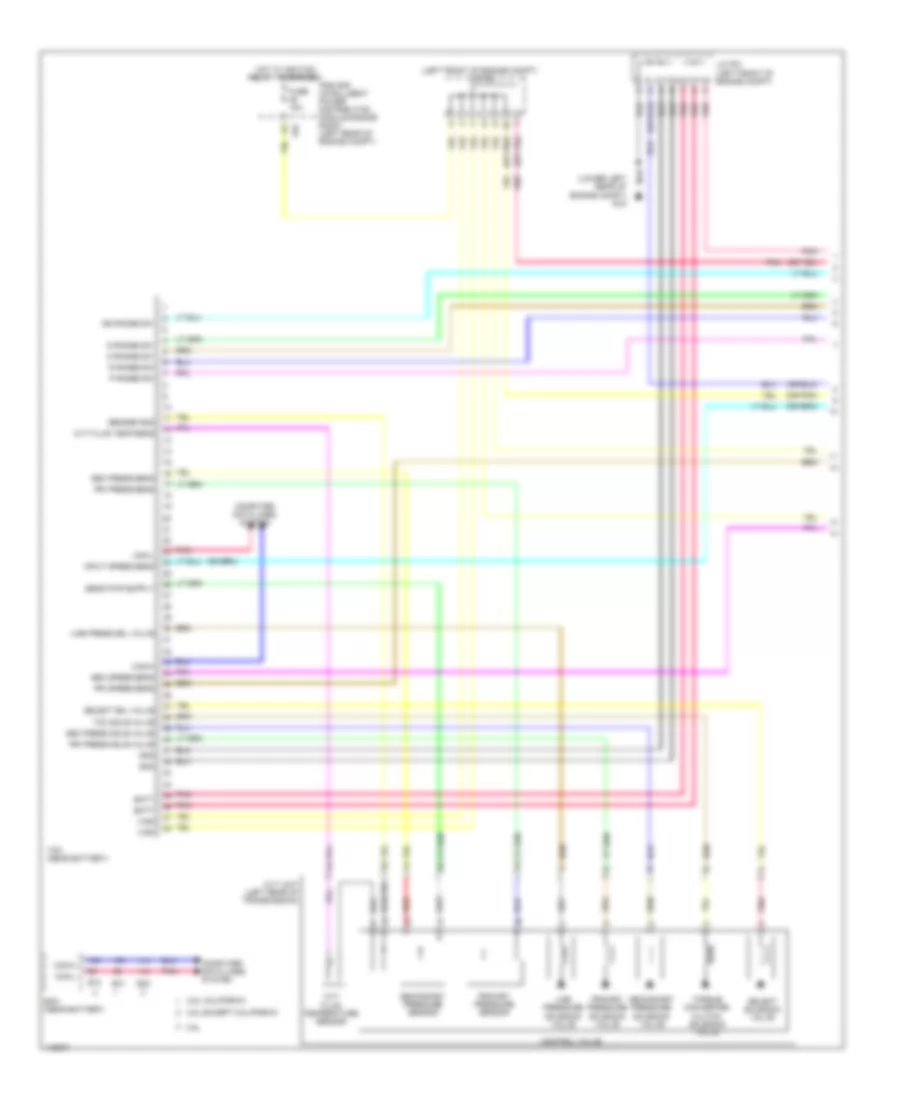
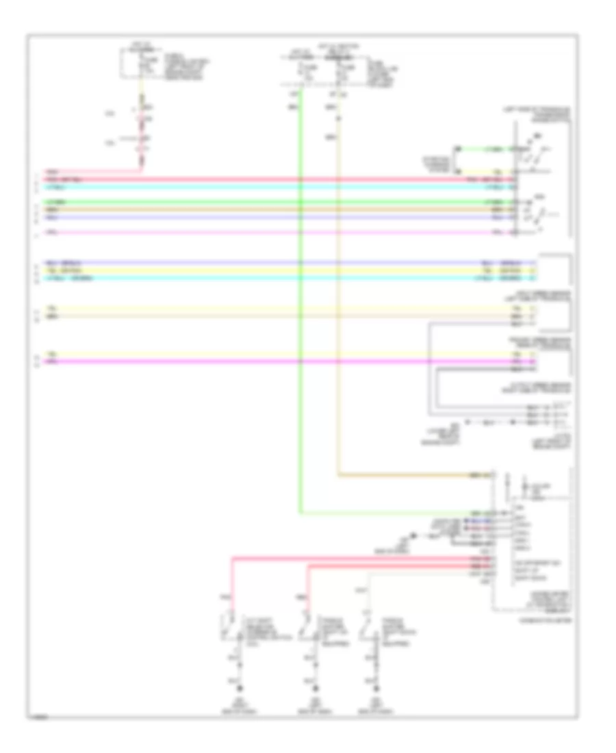
Automatic A/C Wiring Diagram (2 of 2) for Nissan Altima S 2014
List of elements for Automatic A/C Wiring Diagram (2 of 2) for Nissan Altima S 2014:
- (behind right side of radiator) cooling fan motor 2
- (left side of engine compt) e204
- (lower left front of engine) a/c compressor
- (lower left rear of engine compt) e15
- (lower left rear of engine compt) e9
- (or pnk)
- (or red)
- 2.5l
- 2.5l california
- 2.5l except california
- 3.5l
- A/c relay
- Can-h
- Can-l
- Computer data lines system
- Cooling fan motor 1 (behind left side of radiator)
- Cooling fan relay 1
- Cooling fan relay 2 (fuse/fusible link & relay box)
- Cooling fan relay 3 (fuse/fusible link & relay box)
- Cpu
- E10
- E11
- E12
- E15 (lower left rear of engine compt)
- E17
- E18
- E201
- E203
- E203 e12
- E31
- E32
- E63
- Ecm (near battery)
- Ect sens
- Ecv
- Engine controls system
- Engine coolant temperature sensor (2.5l: rear of cylinder head) (3.5l: left rear of engine)
- F14
- F79
- F83
- F88
- F91
- Fuse 10a
- Gnd (sig)
- Hot at all times
- Ig+
- Ignition relay 1
- Ipdm e/r (intelligent power distribution module engine room) (left rear of engine compt)
- J/c f04
- Magnet clutch
- Mtr fan rly hi
- Mtr fan rly mid
- Pnk
- Red
- Refrigerant press sens sens pwr sply
- Refrigerant pressure sensor (left front of engine compt)
- Sens gnd
- Tan
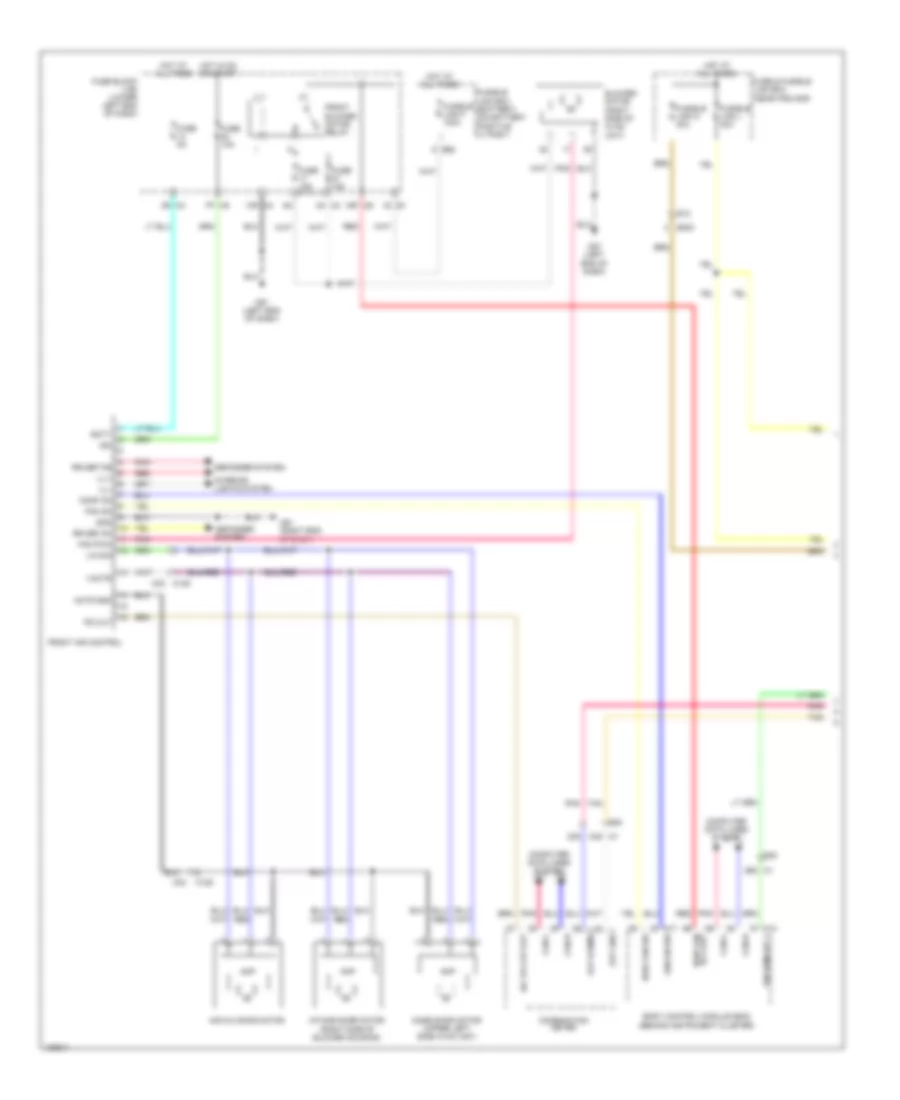
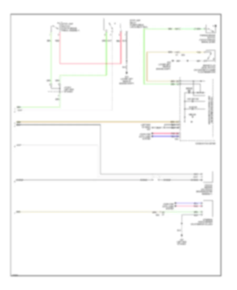
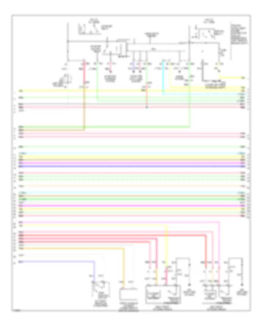
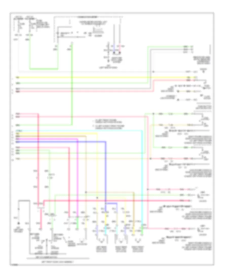
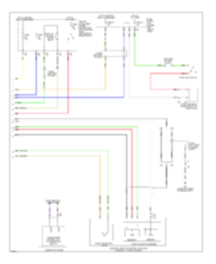
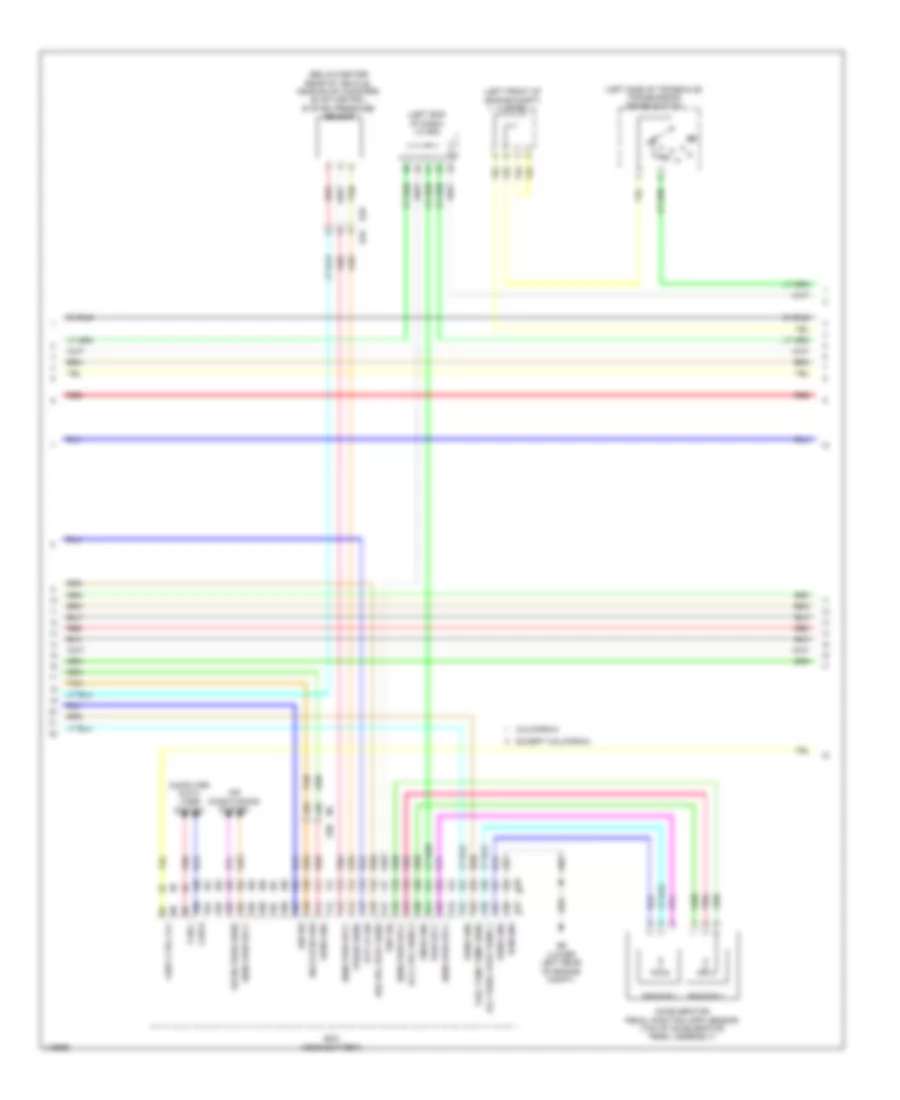
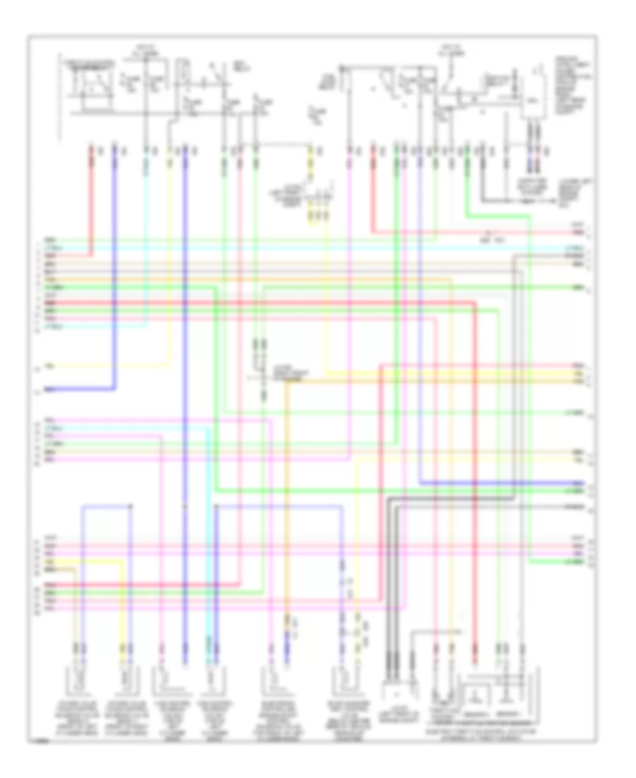
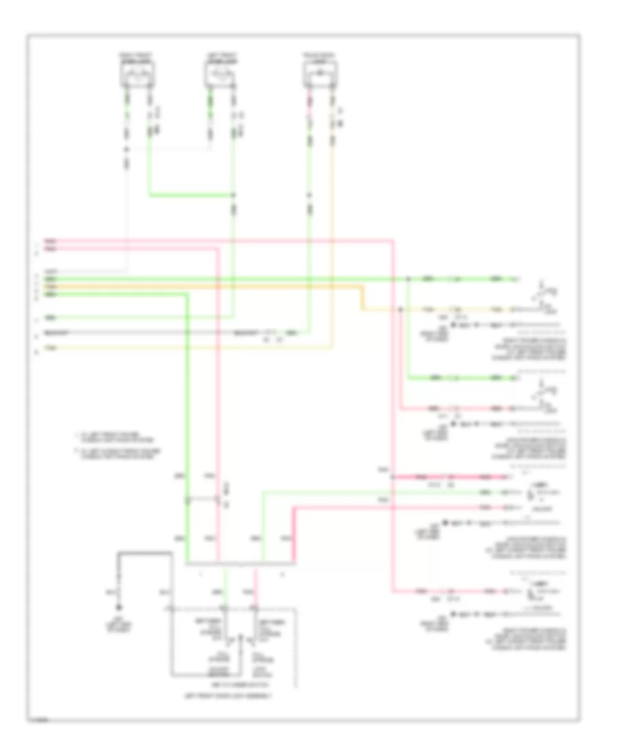
Manual A/C Wiring Diagram (1 of 2) for Nissan Altima S 2014
List of elements for Manual A/C Wiring Diagram (1 of 2) for Nissan Altima S 2014:
- 13r m4
- 16p m5
- 1s e1
- 33g
- 36g m1
- 3n m3
- 3r m4
- A/c pd cut out
- Actr gnd
- Air mix door motor
- Aircon sw
- Amp
- Batt
- Blower motor (right side of hvac unit)
- Body control module (bcm) (behind instrument cluster)
- Bwr fan
- Bwr fan sw
- Can-h
- Can-l
- Combination meter
- Comp on
- Computer data lines system
- Defogger system
- E12
- E203
- E30
- E62
- Fan on
- Fan pwm
- Front air control
- Front blower motor relay
- Fuse & fusible link box (near ipdm e/r)
- Fuse 10a
- Fuse 15a
- Fuse 5a
- Fuse block (j/b) (lower left end of dash)
- Fusible link box (battery) (on battery positive (+) post)
- Fusible link f 100a
- Fusible link l 40a
- Fusible link n 40a
- Gnd
- Hot at all times
- Hot in on or start
- Ign
- Ign usm out 1
- Ill+
- Ill-
- Intake door motor (right side of blower housing)
- Interior lights system
- Lin sig
- M1 34g
- M125
- M17
- M18
- M33
- M5 7p
- M57 (left end of dash)
- M61 (right end of dash)
- Mode door motor (upper left side hvac unit)
- Oat (vamb)
- Out gnd
- Pd cut
- Pnk
- Red
- Rly out
- Rr def f/b
- Rr def on
- Tan
- Vactr
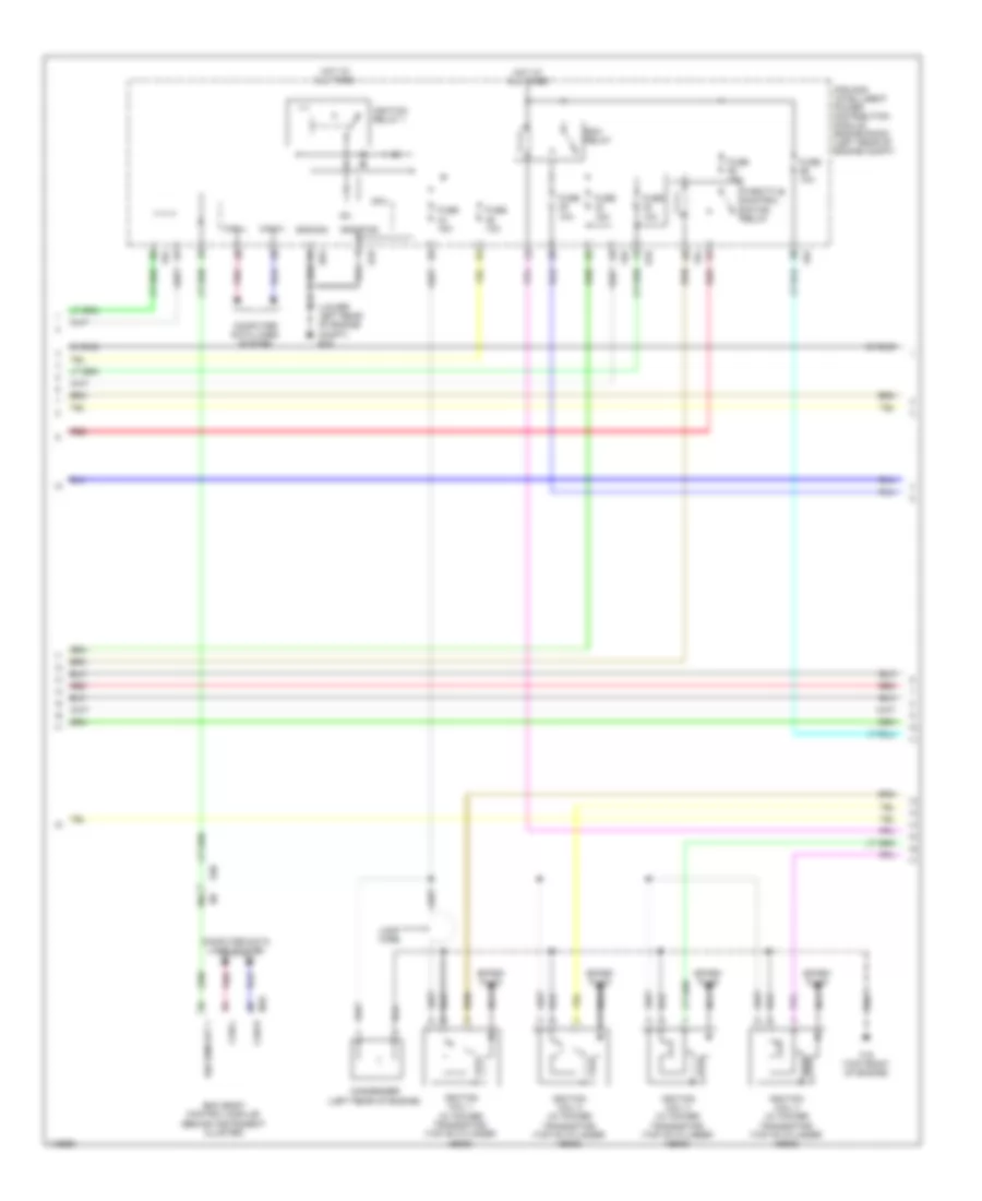
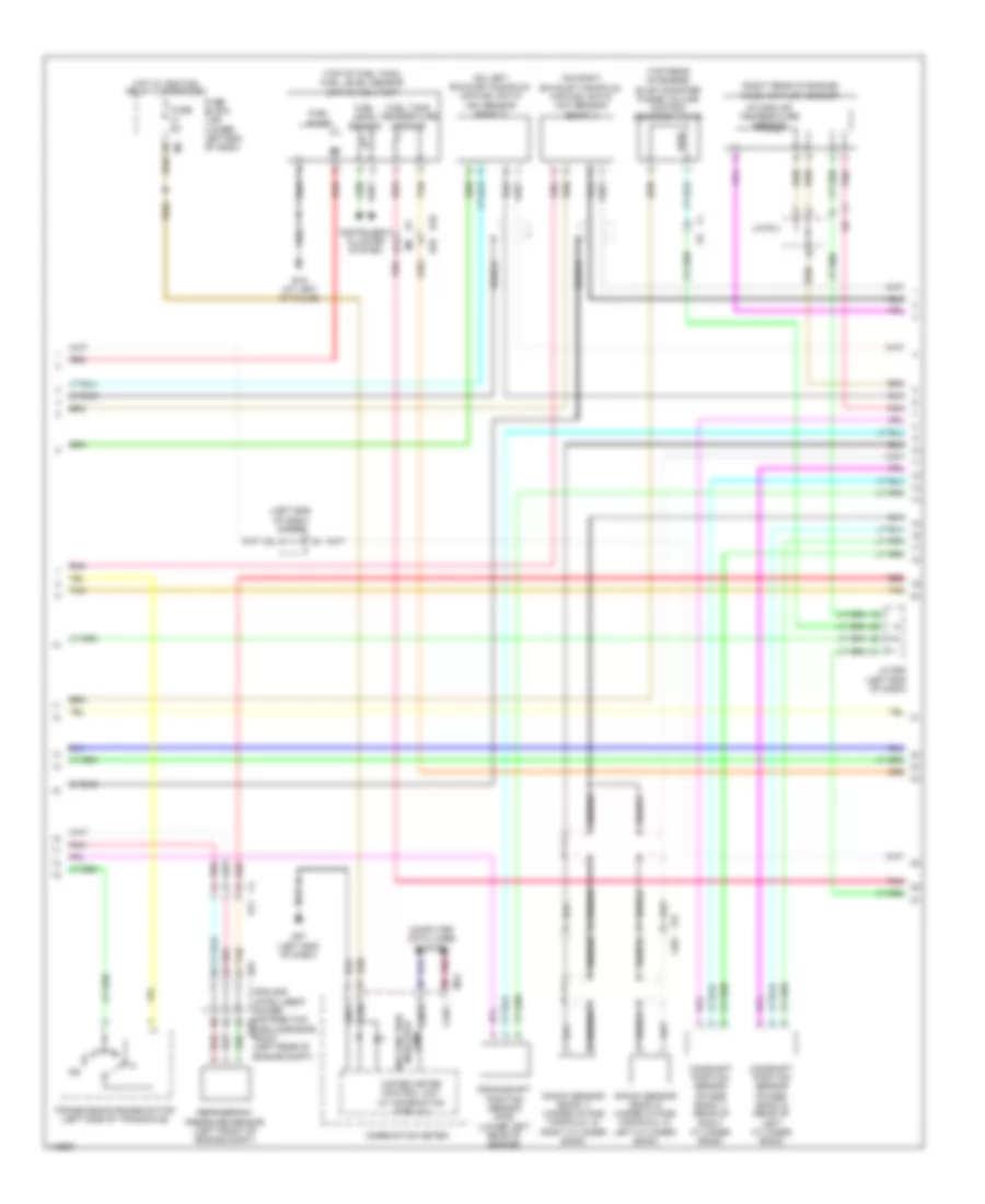
Manual A/C Wiring Diagram (2 of 2) for Nissan Altima S 2014
List of elements for Manual A/C Wiring Diagram (2 of 2) for Nissan Altima S 2014:
- (behind right side of radiator) cooling fan motor 2
- (left side of engine compt) e204
- (lower left rear of engine compt) e9
- (or pnk)
- (or red)
- 2.5l
- 2.5l california
- 2.5l except california
- 3.5l
- A/c compressor (lower left front of engine)
- A/c relay
- Ambient sensor (behind lower left side of front grille)
- Can-h
- Can-l
- Computer data lines system
- Cooling fan motor 1 (behind left side of radiator)
- Cooling fan relay 1
- Cooling fan relay 2 (fuse/fusible link & relay box)
- Cooling fan relay 3 (fuse/fusible link & relay box)
- Cpu
- E10
- E11
- E12
- E15 (lower left rear of engine compt)
- E17
- E18
- E201
- E203
- E203 e12
- E31
- E32
- E63
- Ecm (near battery)
- Ect sens
- Engine controls system
- Engine coolant temperature sensor (2.5l: rear of cylinder head) (3.5l: left rear of engine)
- F14
- F79
- F83
- F91
- Fuse 10a
- Gnd (sig)
- Hot at all times
- Ig+
- Ignition relay 1
- Ipdm e/r (intelligent power distribution module engine room) (left rear of engine compt)
- J/c f04
- Mtr fan rly hi
- Mtr fan rly mid
- Pnk
- Red
- Refrigerant press sens sens pwr sply
- Refrigerant pressure sensor (left front of engine compt)
- Sens gnd
- Tan
ANTI-LOCK BRAKES
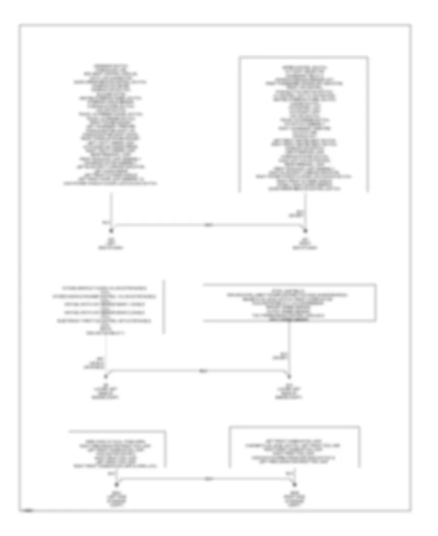
Anti-lock Brakes Wiring Diagram (1 of 2) for Nissan Altima S 2014
List of elements for Anti-lock Brakes Wiring Diagram (1 of 2) for Nissan Altima S 2014:
- 14g m1
- 5m e6
- 8p m5
- Abs actuator & electric unit (control unit) (right rear of engine compt)
- Abs/tcs/vdc control unit
- Actuator
- B10
- B43
- Bls
- Can-h
- Can-l
- Computer data lines system
- Dp fl
- Dp fr
- Dp rl
- Dp rr
- Ds fl
- Ds fr
- Ds rl
- Ds rr
- E29
- E30
- E33 (right rear of engine compt)
- E63
- Fl in
- Fl out
- Fr in
- Fr out
- Fuse 10a
- Fuse 5a
- Fuse block (j/b) (lower left end of dash)
- Fuse/fusible link & relay box (near ipdm e/r)
- Fusible link g 40a
- Fusible link h 40a
- Gnd
- Gnd ext
- Hot at all times
- Hot in on or start
- Hsv 1
- Hsv 2
- Interior lights system
- Ipdm e/r (intelligent power distribution module engine room) (left rear of engine compt)
- J/c e08 (left end of dash)
- Left front wheel sensor (on left front wheel hub assembly)
- Left rear wheel sensor (on left rear wheel hub assembly)
- M57 (left end of dash)
- Motor
- Motor relay
- Pnk
- Red
- Relay unit
- Right front wheel sensor (on right front wheel hub assembly)
- Right rear wheel sensor (on right rear wheel hub assembly)
- Rl in
- Rl out
- Rr in
- Rr out
- Shield
- Solenoid valve relay
- U5v ext
- Usv1
- Usv2
- Vac
- Vdc off
- Vdc off switch
- Wav
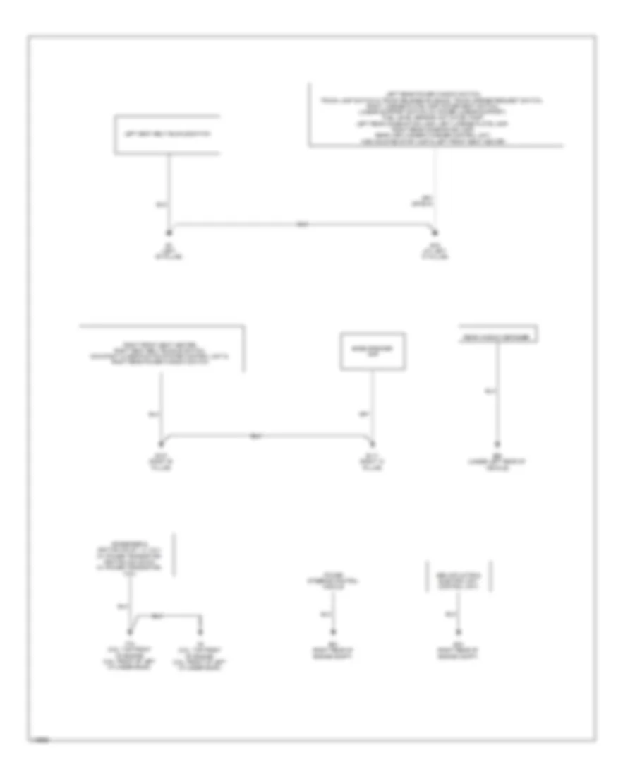
Anti-lock Brakes Wiring Diagram (2 of 2) for Nissan Altima S 2014
List of elements for Anti-lock Brakes Wiring Diagram (2 of 2) for Nissan Altima S 2014:
- (left end of dash) m57
- 11g
- 12g
- Abs ind
- Brake fluid level switch (on master cylinder fluid reservoir)
- Brake ind
- Combination meter
- Computer data lines system
- E15 (lower left rear of engine compt)
- E30
- J/c e10 (left end of dash)
- M24
- M57 (left end of dash)
- Parking brake switch (top of parking brake lever)
- Pnk
- Red
- Shield
- Slip ind
- Steering angle sensor (on steering column)
- Stop lamp relay (fuse/fusible link & relay box)
- Stop lamp switch (top of brake pedal assembly)
- Tan
- Unified meter control unit (w/ information display)
- Vacuum sensor (on vacuum brake booster assembly)
- Vdc off ind
ANTI-THEFT
Forced Entry Wiring Diagram (1 of 4) for Nissan Altima S 2014
List of elements for Forced Entry Wiring Diagram (1 of 4) for Nissan Altima S 2014:
- (left end of dash) m57
- +5v sply
- 10r
- 13g
- 15g
- 4n m3
- 5m e6
- 76j
- 85j
- 86j m6
- 8m e6
- Acc led
- As door ant a
- As door ant b
- As door switch
- As request switch
- At device out
- Audio dongle
- Bat bcm fuse
- Bat front door
- Bat power f/l
- Bat rear door
- Bat saver out
- Bcm (body control module) (behind instrument cluster)
- Brake sw fuse
- Brake sw lamp
- Buzzer out
- Can-h
- Can-l
- Central lock switch
- Central unlock switch
- Computer data lines system
- Dongle unit (canada) (upper center of dash)
- Door key/c lock switch
- Door key/c unlock switch
- Door lock dr/as/fl
- Door lock rr/rl
- Door unlock as
- Door unlock dr/fl
- Dr door ant a
- Dr door ant b
- Dr door lock status
- Dr door switch
- Dr request switch
- Dr unlock rr/rl
- E15 (lower left rear of engine compt)
- E30
- Eng start switch no escl
- Exterior lights system
- Fl flasher
- Fr flasher
- Fuse & fusible link box
- Fuse 10a
- Fuse 15a
- Fuse block (j/b) (lower left end of dash)
- Fusible link i 40a
- Gnd
- Gnd rf a/l
- Gnd1
- Gnd2
- Hazard switch
- Hot at all times
- Ign usm out 1
- Intelligent key warning buzzer (left rear of engine compt)
- Interior lights system
- J/c e10 (left end of dash)
- M17
- M18
- M19
- M20
- M21
- M4 9r
- M61 (right end of dash)
- Pnk
- Pw lin
- Rear bumper ant a
- Rear bumper ant b
- Rear bumper antenna (behind center of rear bumper)
- Red
- Rf nimoco
- Rl door switch
- Room ant 2 a
- Room ant 2 b
- Room lamp cont
- Rr door switch
- Security ind
- Shift n/p
- Shift p
- Starter relay out
- Stop lamp relay (fuse/fusible link & relay box)
- Stop light switch
- Tan
- Trunk ant 3 a
- Trunk ant 3 b
- Trunk open sw
- Trunk request switch
- Trunk switch
- Trunk, tailgate, fuel doors system
Forced Entry Wiring Diagram (2 of 4) for Nissan Altima S 2014
List of elements for Forced Entry Wiring Diagram (2 of 4) for Nissan Altima S 2014:
- (if equipped)
- 31g
- 36g m1
- Computer data lines system
- Cpu
- Cvt shift selector (if equipped)
- D101
- D114
- E15 (lower left rear of engine compt)
- E18
- E201
- E30
- E63
- F10
- F83
- F84
- Front console antenna (under rear of center console)
- Fuse 10a
- Headlights system
- Horns system
- Hot at all times
- Ignition relay 1
- Ipdm e/r (intelligent power distribution module engine room) (left rear of engine compt)
- J/c e08 (left end of dash)
- Left front outside handle
- M1 37g
- M112
- M14
- M57 (left end of dash)
- M61 (right end of dash)
- M84
- Outside key antenna
- Park position switch
- Pnk
- Red
- Request switch
- Right front outside handle
- Starter control relay
- Starter relay
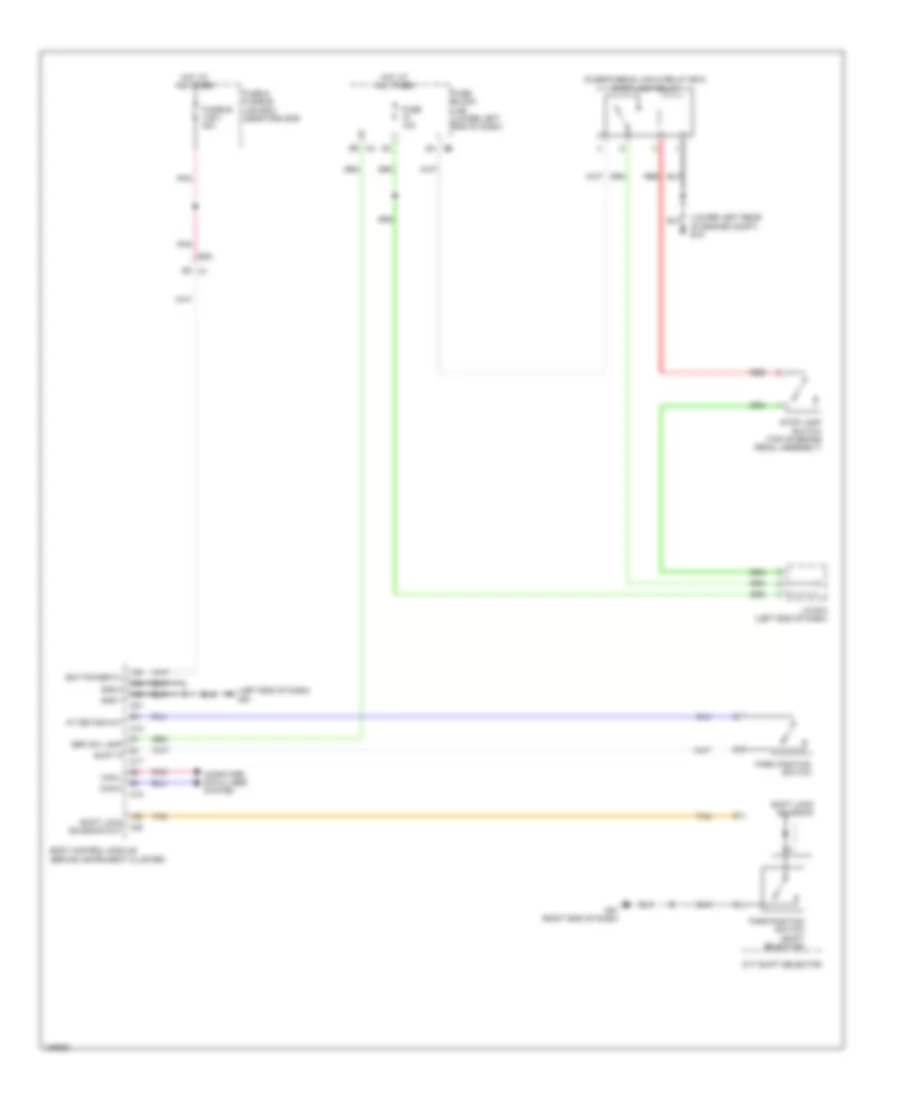
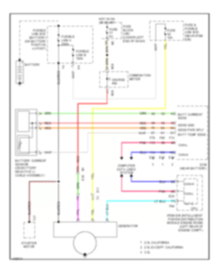
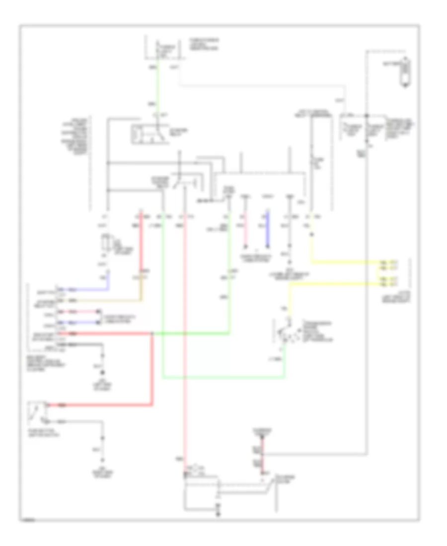
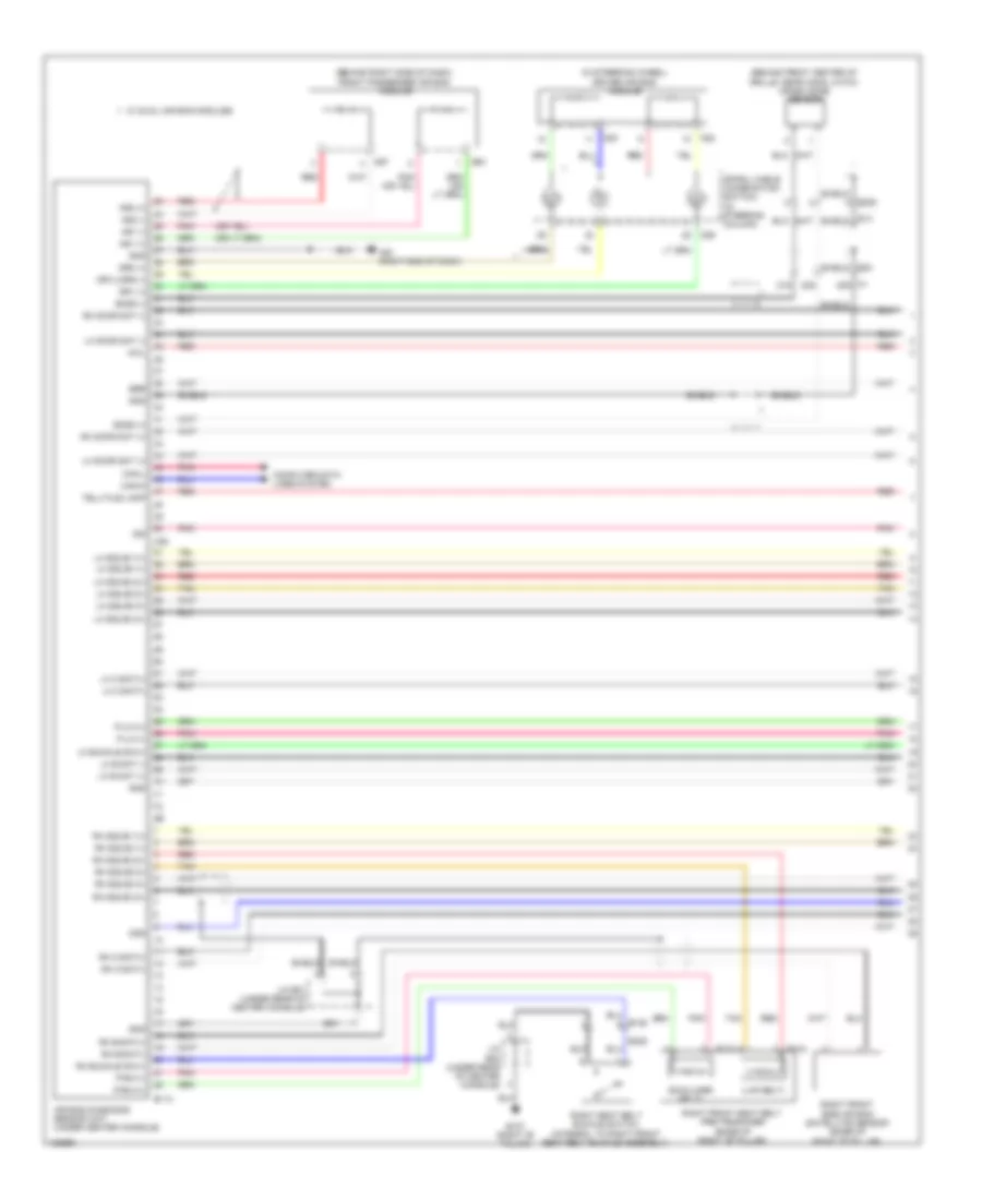
- Starting/ charging system
- Tan
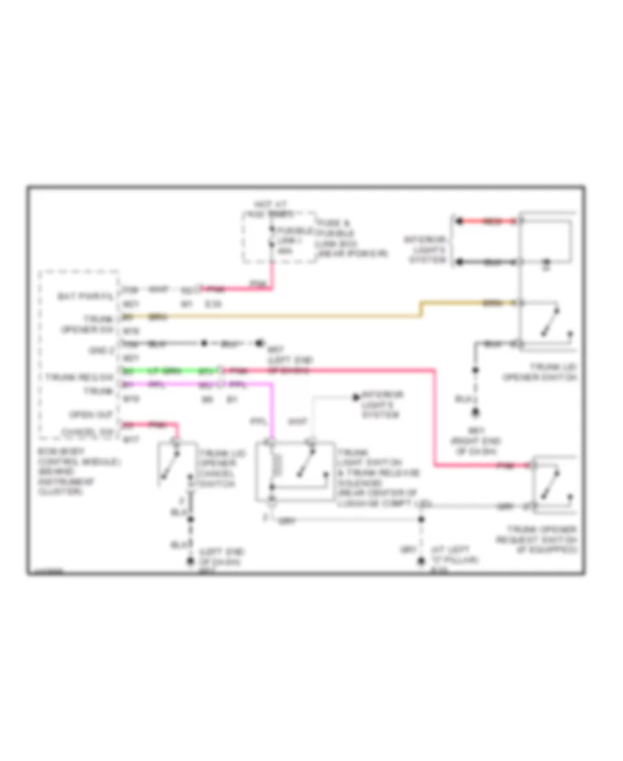
Forced Entry Wiring Diagram (3 of 4) for Nissan Altima S 2014
List of elements for Forced Entry Wiring Diagram (3 of 4) for Nissan Altima S 2014:
- 77j m6
- 83j
- 84j
- 87j
- B104
- B19 (at left "c" pillar)
- E209 (right side of engine compt)
- Hood switch or pre-wireing for hood switch (center front engine compt)
- J/c f02 (left front of engine compt)
- Left front door switch (in left "b" pillar)
- Left rear door switch (at left "c" pillar)
- M10
- M6 78j
- Pnk
- Rear parcel shelf antenna (under center of rear parcel shelf)
- Red
- Right front door switch (in right "b" pillar)
- Right rear door switch (at right "c" pillar)
- Tan
- Transmission range switch (left side of transaxle)
- Trunk lamp switch & trunk release solenoid (rear center of trunk lid)
- Trunk opener request switch
Forced Entry Wiring Diagram (4 of 4) for Nissan Altima S 2014
List of elements for Forced Entry Wiring Diagram (4 of 4) for Nissan Altima S 2014:
- 12r m4
- 13p m5
- 97j
- Acc/on
- Actuator
- B104
- B106
- Between full stroke & n
- Buzzer
- Combination meter
- Computer data lines system
- Cpu
- D101
- D114
- D201
- D301
- Door unlock sensor
- Full stroke
- Fuse 10a
- Fuse 5a
- Fuse block (j/b) (lower left end of dash)
- Hot at all times
- Illumi- nation
- Interior lights system
- Key cylinder switch
- Key ind
- Left front door lock assembly
- Left rear door lock actuator
- Lock
- Lock switch
- M10
- M11
- M11 d1
- M112
- M14
- M24
- M57 (left end of dash)
- M6 98j
- M61 (right end of dash)
- M84
- Main power window & door lock/unlock switch (w/ left & right front power window anti-pinch system)
- Main power window & door lock/unlock switch (w/ left front power window anti-pinch system)
- Pnk
- Push button ignition switch
- Push switch
- Red
- Remote keyless entry receiver (upper right end of dash)
- Right front door lock actuator
- Right power window & door lock/unlock switch (w/ left & right front power window anti-pinch system)
- Right power window & door lock/unlock switch (w/ left front power window anti-pinch system)
- Right rear door lock actuator
- Security ind
- Tan
- Un lock
- Unified meter control unit (w/ information display)
- Unlock
- Unlock switch
- W/ left & right front power window anti-pinch system
- W/ left front power
- Window anti-pinch system
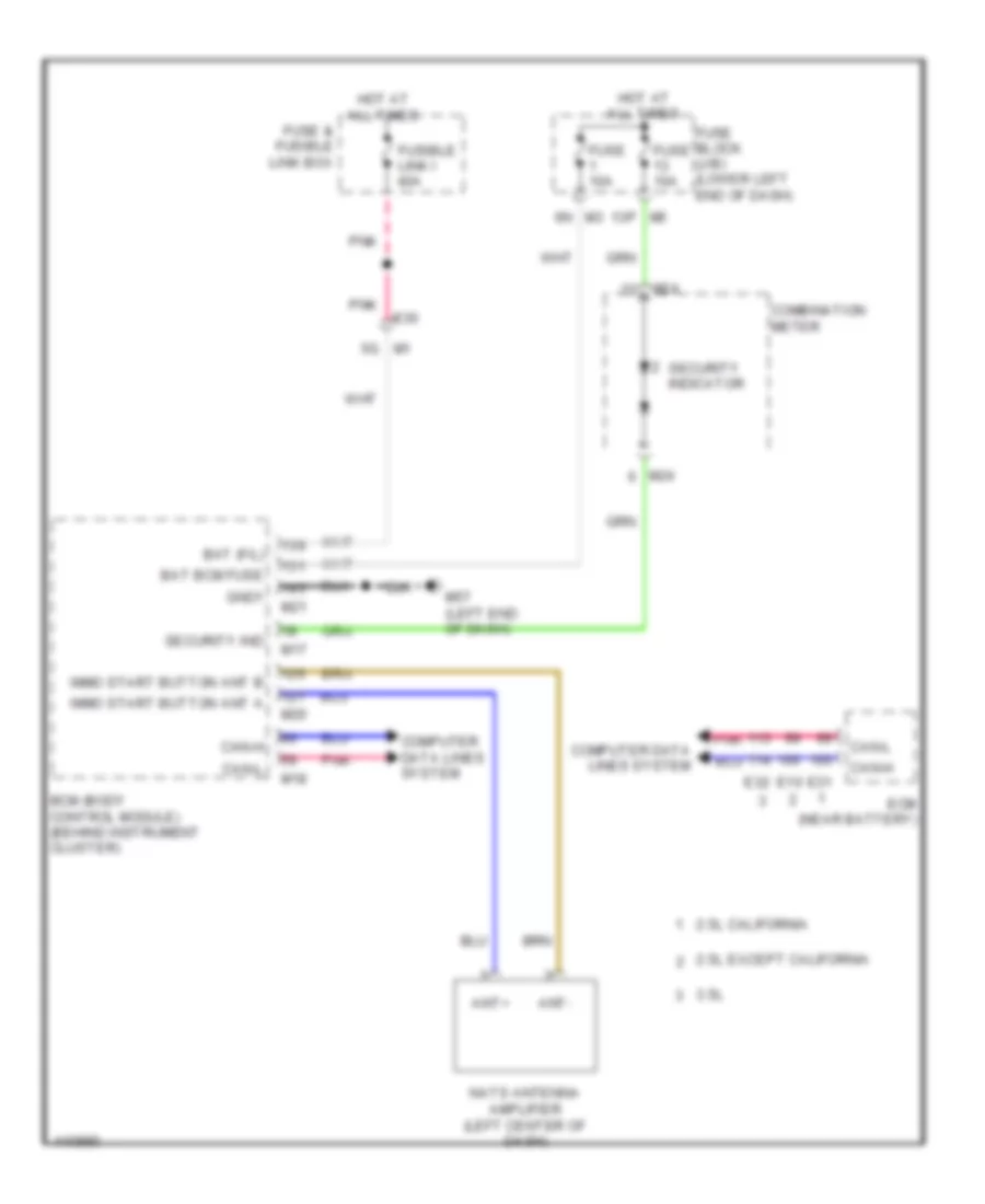
Immobilizer Wiring Diagram for Nissan Altima S 2014
List of elements for Immobilizer Wiring Diagram for Nissan Altima S 2014:
- 13p
- 2.5l california
- 2.5l except california
- 3.5l
- Ant+
- Ant-
- Bat (f/l)
- Bat bcm fuse
- Bcm (body control module) (behind instrument cluster)
- Can-h
- Can-l
- Combination meter
- Computer data lines system
- E10
- E30
- E31
- E32
- Ecm (near battery)
- Fuse & fusible link box
- Fuse 10a
- Fuse block (j/b) (lower left end of dash)
- Fusible link i 40a
- Gnd1
- Hot at all times
- Immo start button ant a
- Immo start button ant b
- M1 5g
- M17
- M18
- M20
- M21
- M24
- M57 (left end of dash)
- Nats antenna amplifier (left center of dash)
- Pnk
- Security ind
- Security indicator
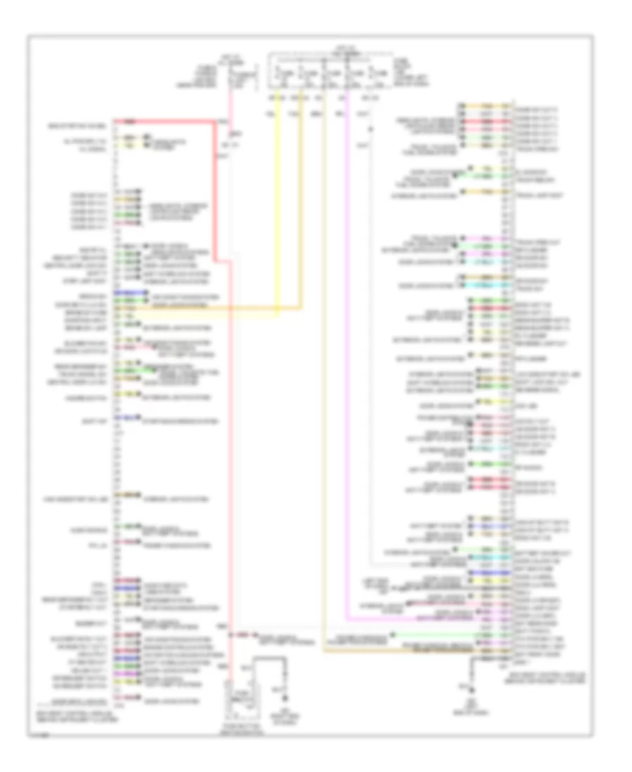
BODY CONTROL MODULES
Body Control Modules Wiring Diagram for Nissan Altima S 2014
List of elements for Body Control Modules Wiring Diagram for Nissan Altima S 2014:
- (left end of dash) m57
- 10r m4
- 5g m1
- 6n m3
- 9p m5
- A/l pwr sply 5v
- A/l signal
- Acc led
- Acc rly out
- Air conditioning system
- Aircon sw
- Anti-theft system
- As door ant a
- As door ant b
- As door sw
- As request switch
- At device out
- Audio dongle
- Bat bcm fuse
- Bat front door
- Bat rear door
- Batt pwr f/l
- Battery saver out
- Bcm (body control module) (behind instrument cluster)
- Blower fan rly out
- Blower fan sw
- Brake sw fuse
- Brake sw lamp
- Buzzer out
- Can-h
- Can-l
- Central door lock sw
- Central door ulk sw
- Combi sw in 1
- Combi sw in 2
- Combi sw in 3
- Combi sw in 4
- Combi sw in 5
- Combi sw out 1
- Combi sw out 2
- Combi sw out 3
- Combi sw out 4
- Combi sw out 5
- Computer data lines system
- Defogger system
- Door key/c lock sw
- Door key/c ulk sw
- Door lk dr/as/fl
- Door lk rr/rl
- Door locks & anti-theft systems
- Door locks & headlights systems
- Door locks system
- Door ulk dr/fl
- Door ulk rr/rl
- Door unlock as
- Dr door ant a
- Dr door ant b
- Dr door lk status
- Dr door sw
- Dr request switch
- E30
- Eng start sw no esl
- Engine controls system
- Exterior lights system
- Fl flasher
- Fr flasher
- Fuse & fusible link box (near ipdm e/r)
- Fuse 10a
- Fuse 15a
- Fuse 5a
- Fuse block (j/b) (lower left end of dash)
- Fusible link i 40a
- Gnd 1
- Gnd 2
- Gnd rf a/l
- Hazard switch
- Headlights system
- Headlights, interior lights & exterior lights systems
- High side start sw led
- Hot at all times
- Ign elec rly out 2
- Ign usm out 1
- Immo st butt ant a
- Immo st butt ant b
- Interior lights system
- Low side start sw led
- M17
- M18
- M19
- M20
- M21
- M57 (left end of dash)
- M61 (right end of dash)
- Mr output
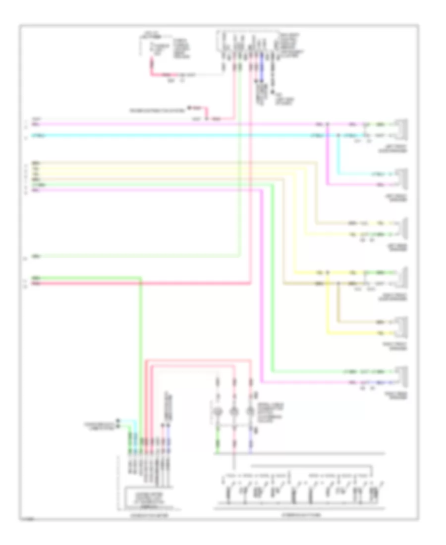
- Navigation & sound systems
- P/w pwr sply bat
- P/w pwr sply ign
- Pnk
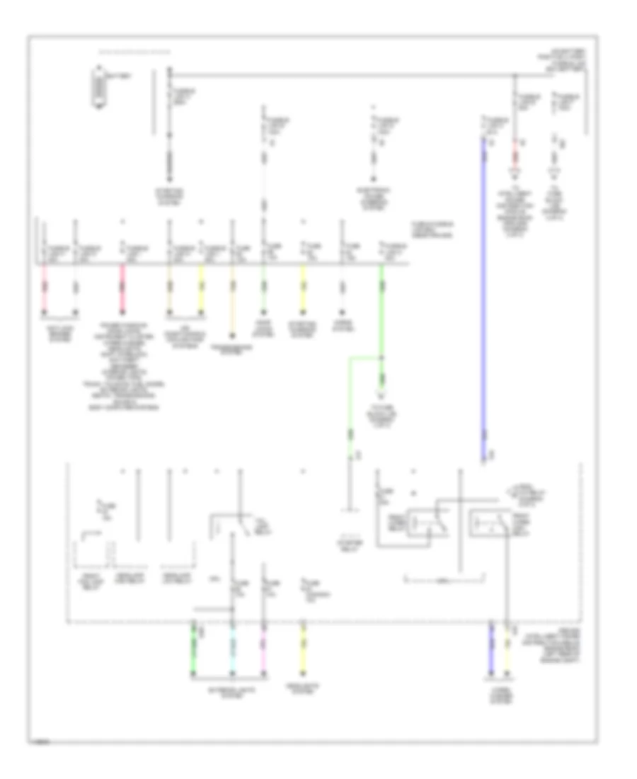
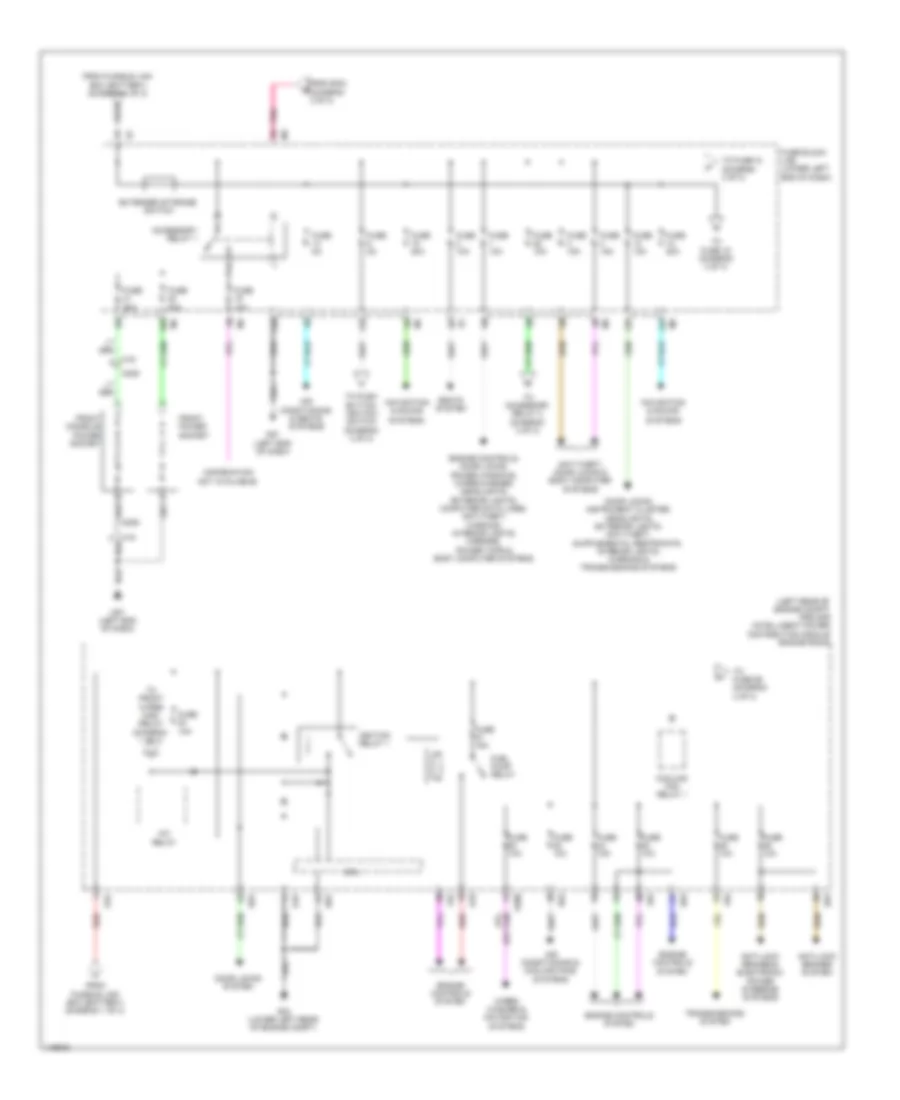
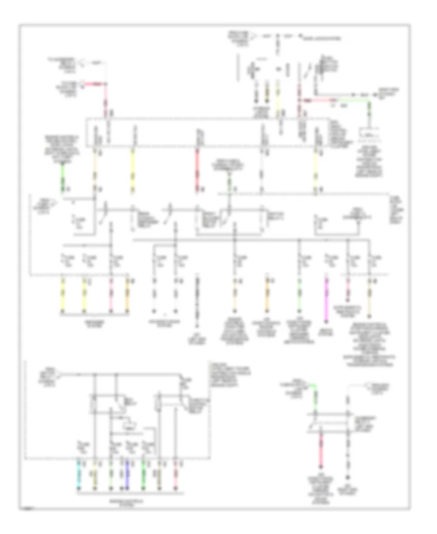
- Power distribution system
- Power windows & power tops systems
- Power windows system
- Power windows, seats & power tops systems
- Push button ignition switch
- Push switch
- Pw lin
- Rear bumper ant a
- Rear bumper ant b
- Rear defogger rly out
- Rear defogger sw
- Red
- Reverse lamp out
- Reverse signal
- Rf nimoco
- Rl door sw
- Rl flasher
- Room ant 2 a
- Room ant 2 b
- Room ant 3 a
- Room ant 3 b
- Room lamp cont
- Rr door sw
- Rr flasher
- Security indicator
- Shift interlock system
- Shift lock sol out
- Shift n/p
- Shift p
- Shorting input
- Starter rly out
- Starting/charging system
- Step lamp cont
- Tan
- Trunk cancel sw
- Trunk lamp cont
- Trunk open out
- Trunk open sw
- Trunk req sw
- Trunk sw
- Trunk, tailgate, fuel doors system
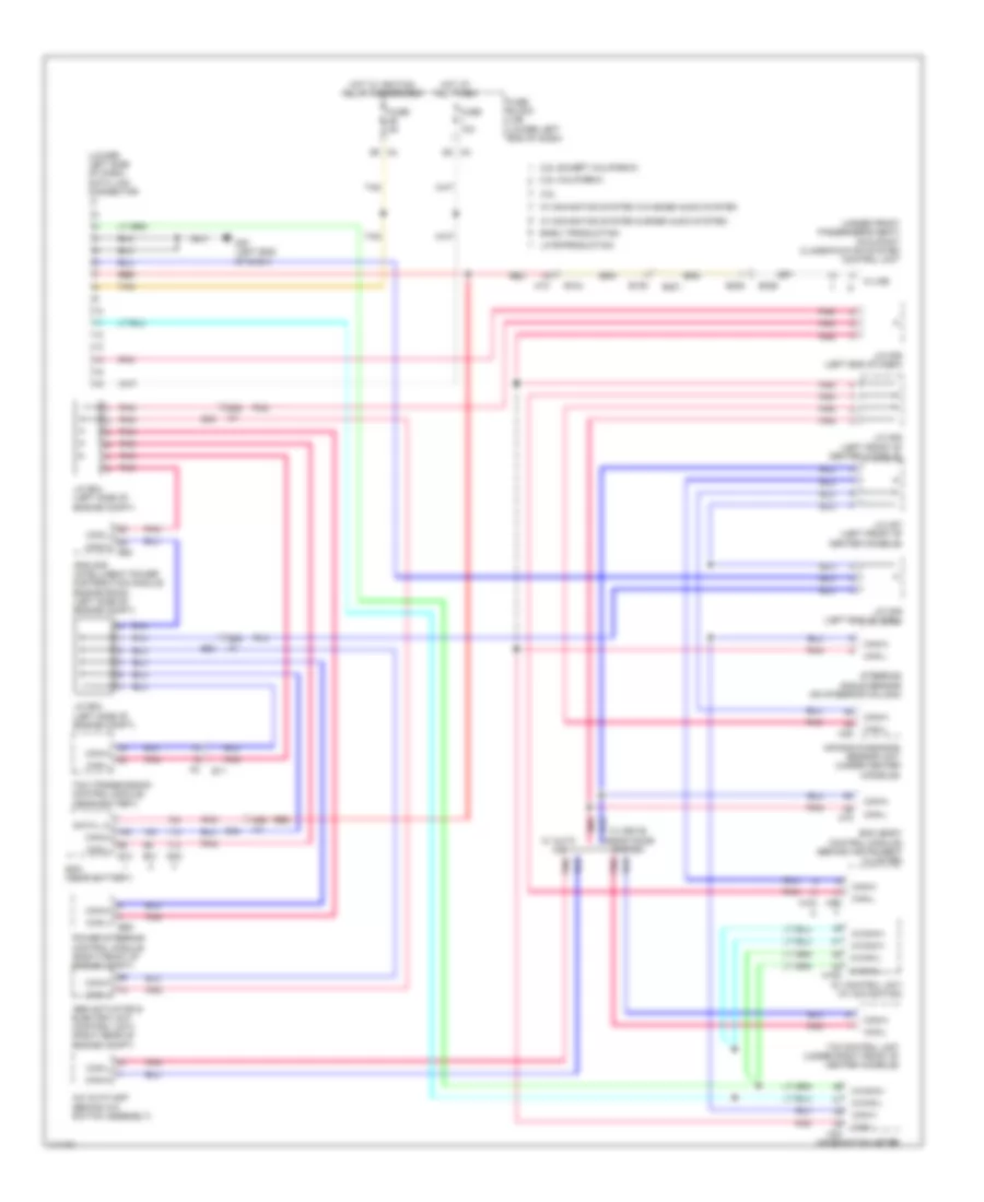
COMPUTER DATA LINES
Computer Data Lines Wiring Diagram for Nissan Altima S 2014
List of elements for Computer Data Lines Wiring Diagram for Nissan Altima S 2014:
- (lower left side of dash) data link connector
- (under front passenger's seat) occupant classification system control unit
- 2.5l california
- 2.5l except california
- 22g
- 23g
- 3.5l
- 45g m1
- A/c auto amp (behind a/c switch assembly)
- Abs actuator & electric unit (control unit) (right rear of engine compt)
- Air bag diagnosis sensor unit (under center console)
- Av control unit (w/ navigation)
- B104
- B105
- B301
- B308
- B326
- Bcm (body control module) (behind instrument cluster)
- Can-h
- Can-l
- Combination meter
- Data l c
- E10
- E11
- E30
- E31
- E32
- E59
- E63
- Early production
- Ecm (near battery)
- Fuse 10a
- Fuse 5a
- Fuse block (j/b) (lower left end of dash)
- Hot at all times
- Hot w/ ignition relay 2 energized
- Ipdm e/r (intelligent power distribution module engine room) (left side of engine compt)
- Its control unit (under right front of center console)
- J/c e03 (left side of engine compt)
- J/c e04 (left side of engine compt)
- J/c m05 (left end of dash)
- J/c m06 (left end of dash)
- J/c m07 (left front of center console)
- J/c m08 (left front of center console)
- K-line
- Late production
- M-can-h
- M-can-l
- M10
- M151
- M153
- M18
- M24
- M35
- M57 (left end of dash)
- M96
- Pnk
- Power steering control module (right front of engine compt)
- Red
- Steering angle sensor (on steering column)
- Tan
- Tcm (transmission control module) (near battery)
- W/ auto a/c
- W/ drive assistance system
- W/ navigation system & bose audio system
- W/ navigation system w/o bose audio system
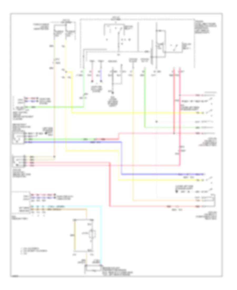
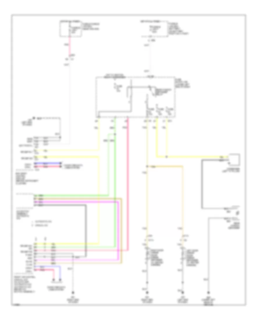
COOLING FAN
Cooling Fan Wiring Diagram for Nissan Altima S 2014
List of elements for Cooling Fan Wiring Diagram for Nissan Altima S 2014:
- (behind right side of radiator) cooling fan motor 2
- (left side of engine compt) e204
- (lower left side of engine compt) e9
- 2.5l
- 2.5l california
- 2.5l except california
- 3.5l
- 36g m1
- Body control module (behind instrument cluster)
- Can-h
- Can-l
- Computer data lines system
- Cooling fan motor 1 (behind left side of radiator)
- Cooling fan relay 1
- Cooling fan relay 2 (fuse/fusible link & relay box)
- Cooling fan relay 3 (fuse/fusible link & relay box)
- Cpu
- E10
- E12
- E15 (lower left rear of engine compt)
- E17
- E18
- E203
- E203 e12
- E30
- E31
- E32
- E63
- Ecm (near battery)
- Ect sens
- Engine coolant temperature sensor (2.5l: rear of cylinder head) (3.5l: left rear of engine)
- F14
- F79
- F91
- Fuse & fusible link box (near ipdm e/r)
- Fuse 10a
- Fusible link l 40a
- Fusible link n 40a
- Gnd-(sig)
- Hot at all times
- Ig+
- Ign vsm out 1 m18
- Ignition relay 1
- Ipdm e/r (intelligent power distribution module engine room) (left rear of engine compt)
- J/c f04
- Mtr fan rly hi
- Mtr fan rly mid
- Pnk
- Red
- Sens gnd
- Tan
CRUISE CONTROL
Cruise Control Wiring Diagram (1 of 2) for Nissan Altima S 2014
List of elements for Cruise Control Wiring Diagram (1 of 2) for Nissan Altima S 2014:
- (left front of engine compt) j/c f02
- (or pnk)
- (or red)
- (or tan)
- (rear of transaxle) primary speed sensor
- (right side of transaxle) output speed sensor
- (top of brake pedal assembly) (w/ ascd) brake pedal position switch
- 2.5l
- 2.5l california
- 2.5l except california
- 3.5l
- 42g
- 43g
- Accel/ resume switch
- Accelerator pedal position sensor (top of accelerator pedal assembly)
- Apps1
- Apps2
- Ascd steering sw
- Ascd steering switch (if equipped)
- Brake pedal position sw
- Can-h
- Can-l
- Cancel switch
- Coast/set switch
- Combination switch (spiral cable) (in steering column)
- Computer data lines system
- E10
- E15 (lower left rear of engine compt)
- E23
- E30
- E31
- E32
- E9 (lower left rear of engine compt)
- Ecm (near battery)
- F13
- F14
- F25
- F78
- F90
- F91
- Gnd
- Ign sw
- Input spd
- Input speed sensor (left side of transaxle)
- J/c f03 (left front of engine compt)
- M30
- M88
- On/off (main) switch
- Out spd sens
- Pnk
- Pri spd sens
- Pwr sply
- Red
- Sens
- Sens gnd
- Sens pwr sply
- Sensor 1
- Sensor 2
- Shield
- Stop lamp sw
- Tan
- Tcm (near battery)
- Throttle ctrl mtr (close)
- Throttle ctrl mtr (open)
- Throttle ctrl mtr pwr sply
- Throttle ctrl mtr rly
- Throttle position sens 1
- Throttle position sens 2
- Vign
Cruise Control Wiring Diagram (2 of 2) for Nissan Altima S 2014
List of elements for Cruise Control Wiring Diagram (2 of 2) for Nissan Altima S 2014:
- (left end of dash) j/c e10
- (or pnk)
- (or shield)
- (or tan)
- 10a
- 15a
- 2.5l
- 3.5l
- Can-h
- Can-l
- Combination meter
- Computer data lines system
- E18
- E63
- E9 (lower left rear of engine compt)
- Electric throttle control actuator (integral w/ throttle body)
- F83
- F84
- Fuse
- Fuse 10 10a
- Fuse 30 10a
- Fuse block (j/b) (lower left end of dash)
- Hot at all times
- Hot w/ ignition relay 1 energized
- Hot w/ ignition relay 2 energized
- Ipdm e/r (intelligent power distribution module engine room) (left rear of engine compt)
- J/c e08 (left end of dash)
- J/c f01 (left front of engine compt)
- M24
- Pnk
- Red
- Sensor 1
- Sensor 2
- Shield
- Stop lamp relay (fuse/fusible link & relay box)
- Stop light switch
- Tan
- Throttle control motor
- Throttle control motor relay
- Throttle position sensor
- Unified meter control unit (w/ information display)
DEFOGGERS
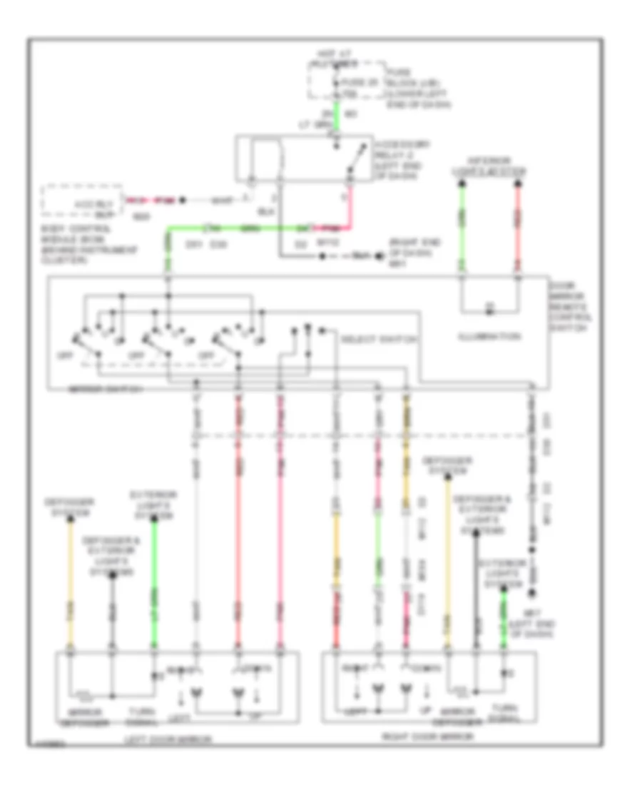
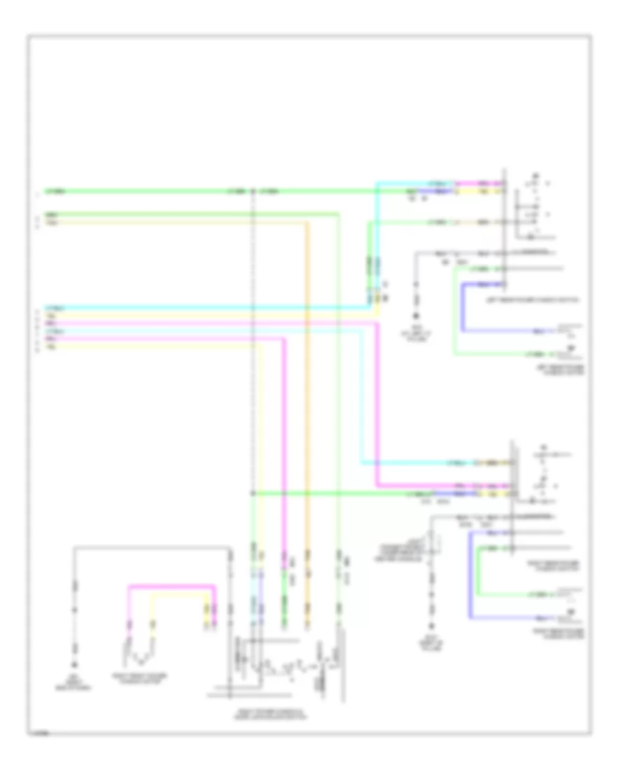
Defoggers Wiring Diagram for Nissan Altima S 2014
List of elements for Defoggers Wiring Diagram for Nissan Altima S 2014:
- (on battery positive (+) post)
- A/c switch assembly (automatic a/c)
- Automatic a/c
- B13
- B53
- B54
- B58 (under left rear of vehicle)
- Bat pwr f/l m21
- Bcm (body control module) (behind instrument cluster)
- Can-h
- Can-l
- Computer data lines system
- Condenser (left "c" pillar)
- D114
- E30
- E62
- Front air control (manual a/c) a/c auto amp (automatic a/c) (automatic a/c: behind a/c switch assembly)
- Fuse & fusible link box (near ipdm e/r)
- Fuse 10a
- Fuse 15a
- Fuse block (j/b) (lower left end of dash)
- Fusible link box (battery)
- Fusible link f 100a
- Fusible link i 40a
- Gnd
- Gnd2 gnd1
- Hot at all times
- Hot w/ ignition relay 2 energized
- Ign
- Left door mirror (door mirror defogger) (w/ heated mirrors)
- M112
- M18
- M57 (left end of dash)
- M61 (right end of dash)
- M84
- Manual a/c
- P gnd
- Pnk
- Rear window defogger
- Rear window defogger relay
- Right door mirror (door mirror defogger) (w/ heated mirrors)
- Rr def f/b
- Rr def rly m18
- Rr def sw
- Rr def sw m17
- Rx fr
- Tan
- Tx fr
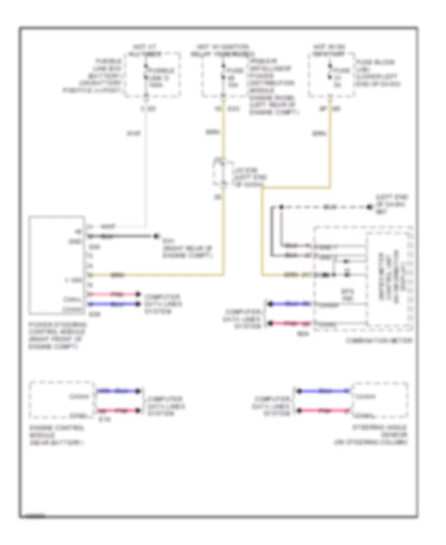
ELECTRONIC POWER STEERING
Electronic Power Steering Wiring Diagram for Nissan Altima S 2014
List of elements for Electronic Power Steering Wiring Diagram for Nissan Altima S 2014:
- (left end of dash) m57
- Can-h
- Can-l
- Combination meter
- Computer data lines system
- Display) (w/ information control unit unified meter
- E10
- E59
- E60
- E61 (right rear of engine compt)
- E63
- Engine control module (near battery)
- Eps ind
- Fuse 10a
- Fuse 5a
- Fuse block (j/b) (lower left end of dash)
- Fusible link box (battery) (on battery positive (+) post)
- Fusible link d 100a
- Gnd
- Gnd 1
- Gnd 2
- Hot at all times
- Hot in on or start
- Hot w/ ignition relay 1 energized
- Ign
- Ipdm e/r (intelligent power distribution module engine room) (left rear of engine compt)
- J/c e08 (left end of dash)
- M24
- Pnk
- Power steering control module (right front of engine compt)
- Steering angle sensor (on steering column)
- V ign
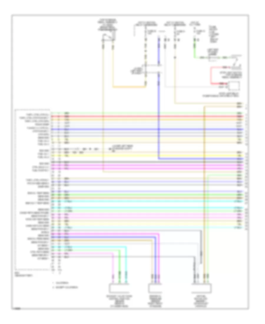
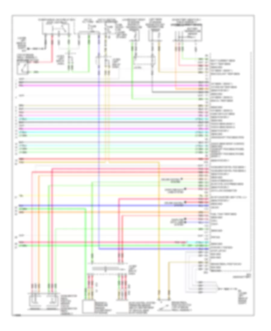
ENGINE PERFORMANCE
2.5L
2.5L, Engine Performance Wiring Diagram (1 of 6) for Nissan Altima S 2014
List of elements for 2.5L, Engine Performance Wiring Diagram (1 of 6) for Nissan Altima S 2014:
- (left end of dash) j/c e10
- (lower left rear of engine compt) e9
- (top of brake pedal assembly) (w/ ascd) brake pedal position switch
- A/f sens 1
- Air fuel ration (a/f) sensor 1 (on exhaust manifold)
- California
- Camsh pstn sens (phase)
- Ctrl pstn sens
- Ctrl sold vlv
- E23
- Ecm (near battery)
- Ecm gnd
- Eng colt temp sens
- Eng oil prss sens
- Eng oil temp sens
- Engine oil pressure sensor (right front of engine)
- Except california
- Exhaust valve timing control position sensor (rear of cylinder head)
- F14
- F25
- F91
- Fuel inj 1
- Fuel inj 2
- Fuel inj 3
- Fuel inj 4
- Fuel pump rly
- Fuse 10 10a
- Fuse 30 10a
- Fuse 31 5a
- Fuse block (j/b) (lower left end of dash)
- Hot at all times
- Hot w/ ignition relay 2 energized
- Htd oxygen sens 2
- Intak air temp sens
- J/c e08 (left end of dash)
- Knock snsr
- Mass air flow sens
- Mtr (opn)
- Mtr pwr sply
- Red
- Sens gnd
- Sens per sply
- Sens pwr sply
- Shield
- Snsr gnd
- Stop lamp relay (fuse/fusible link & relay box)
- Stop light switch (top of brake pedal assembly)
- Tan
- Thrtl ctrl mtr (cl)
- Thrtl ctrl mtr (opn)
- Thrtl ctrl mtr pwr sply
- Thrtl ctrl mtr rly
- Tuning vlv mtr (cl)
2.5L, Engine Performance Wiring Diagram (2 of 6) for Nissan Altima S 2014
List of elements for 2.5L, Engine Performance Wiring Diagram (2 of 6) for Nissan Altima S 2014:
- (in exhaust, downstream of catalytic converter) heated oxygen sensor 2
- (left front of engine compt) j/c f01
- (on intake manifold, near throttle body) evap canister purge volume control solenoid valve
- (right front of engine) intake manifold tuning control valve motor
- (right side of cylinder head) cylinder head knock sensor
- Camshaft position sensor (phase) (rear of cylinder head)
- Combination meter
- Computer data lines system
- E23
- E9 (lower left rear of engine compt)
- Electric throttle control actuator (integral w/ throttle body)
- Engine coolant temperature sensor (rear of cylinder head)
- Engine oil temperature sensor (right side of engine)
- F25
- Intake air temperature sensor
- M57 (left end of dash)
- Malfunction indicator lamp (mil)
- Mass air flow sensor (left side of engine compt, attached to air box)
- Pnk
- Red
- Sensor 1
- Sensor 2
- Shield
- Tan
- Throttle control motor
- Throttle position sensor
- Unified meter control unit (w/ information display)
2.5L, Engine Performance Wiring Diagram (3 of 6) for Nissan Altima S 2014
List of elements for 2.5L, Engine Performance Wiring Diagram (3 of 6) for Nissan Altima S 2014:
- (left side of engine compt) j/c f07
- (left side of engine compt) j/c f08
- (top right side of cylinder head) fuel injectors
- 44g
- 81j
- Accel/ resume switch
- Ascd steering switch (if equipped)
- B10
- B19 (at left "c" pillar)
- Cancel switch
- Coast/set switch
- Cpu
- E18
- E201
- E29
- E30
- E63
- F83
- F84
- Fuel level sensor
- Fuel level sensor unit & fuel pump (top of fuel tank)
- Fuel pump
- Fuel pump relay
- Fuel tank temperature sensor
- Fuse 10a
- Fuse 15a
- Hot w/ ignition relay 1 energized
- Instrument cluster system
- Interior lights system
- Ipdm e/r (intelligent power distribution module engine room) (left rear of engine compt)
- M30
- M88
- On/off (main) switch
- Pnk
- Red
- Refrigerant pressure sensor (left front of engine compt)
- Shield
- Spiral cable (in steering column)
- Tan
2.5L, Engine Performance Wiring Diagram (4 of 6) for Nissan Altima S 2014
List of elements for 2.5L, Engine Performance Wiring Diagram (4 of 6) for Nissan Altima S 2014:
- (below center rear of vehicle, near evap canister) evap control system pressure sensor
- (left end of dash) j/c e08
- (left front of engine compt) j/c f02
- (left side of transaxle) transmission range switch
- (lower left rear of engine compt)
- 42g
- 43g
- Acc pedal post sens 1
- Accelerator pedal position (app) sensor (top of accelerator pedal assembly)
- Accl pdl sens 2
- Air conditioning system
- Ascd strg sw
- B10
- Brk pdl post sens
- California
- Can-h
- Can-l
- Computer data lines system
- E10
- E29
- E30
- E31
- Ecm (near battery)
- Ecm gnd
- Except california
- Fuel tank temp sens
- Ign sw
- Pnk
- Pnp sig
- Press sens
- Pwr sply
- Red
- Refrg prss sens
- Sens gnd
- Sens pwr sply
- Sensor 1
- Sensor 2
- Shield
- Snsr gnd
- Stp lp sw
- Tan
- Vent ctrl vlv
2.5L, Engine Performance Wiring Diagram (5 of 6) for Nissan Altima S 2014
List of elements for 2.5L, Engine Performance Wiring Diagram (5 of 6) for Nissan Altima S 2014:
- (lower left rear of engine compt) e15
- 36g
- Bcm (body control module) (behind instrument cluster)
- Can-h
- Can-l
- Computer data lines system
- Condenser (left rear of engine)
- Cpu
- E18
- E30
- E63
- Ecm relay
- F15 (top front of engine)
- F83
- F84
- Fuse 10a
- Fuse 15a
- Gnd-pwr
- Gnd-sig
- Hot at all times
- Ig+
- Ign usm out 1
- Ignition coil 1 (w/ power transistor) (top of cylinder head)
- Ignition coil 2 (w/ power transistor) (top of cylinder head)
- Ignition coil 3 (w/ power transistor) (top of cylinder head)
- Ignition coil 4 (w/ power transistor) (top of cylinder head)
- Ignition relay 1
- Ipdm e/r (intelligent power distribution module engine room) (left rear of engine compt)
- Loop wire
- M18
- Nca
- Pnk
- Red
- Shield
- Spark plug
- Throttle control motor relay
2.5L, Engine Performance Wiring Diagram (6 of 6) for Nissan Altima S 2014
List of elements for 2.5L, Engine Performance Wiring Diagram (6 of 6) for Nissan Altima S 2014:
- (lower left rear of engine compt) e9
- (right front of cylinder bank) intake valve timing intermediate lock control solenoid valve
- (right front of engine) (california) manifold absolute pressure (map) sensor
- (right rear of cylinder head) crankshaft position sensor (pos)
- (top rear of engine) intake manifold runner control valve motor
- A/f sens 1 htr
- B10
- Batt currnt sens
- Batt temp sens
- California
- Crksh post sens (pos)
- Ctrl sol vlv
- Ctrl vlv mtr (cl)
- Ctrl vlv mtr (opn)
- E11
- E23
- E29
- Ecm (near battery)
- Ecm gnd
- Ecm rly
- Evap canister vent control valve (below center rear of vehicle, near evap canister)
- Except california
- Exhaust valve timing control solenoid valve (left front of cylinder head)
- F13
- F25
- F90
- Htd oxygen sens 2 htr
- Ign sig 1
- Ign sig 2
- Ign sig 3
- Ign sig 4
- Intake manifold runner control valve position sensor (right front of engine)
- Intake valve timing control solenoid valve (right front of cylinder head)
- Lck ctrl sol vlv
- Mtr pwr sply
- Prss (map) sens
- Pwr sply
- Red
- Sens gnd
- Sens pwr sply
- Shield
- Starting/ charging system
- Thrtl post sens 1
- Thrtl post sens 2
- Vlv pstn sens
3.5L
3.5L, Engine Performance Wiring Diagram (1 of 4) for Nissan Altima S 2014
List of elements for 3.5L, Engine Performance Wiring Diagram (1 of 4) for Nissan Altima S 2014:
- (left front of engine compt)
- (left side of engine compt) j/c f07
- (lower left rear of engine compt) e9
- (rear of left cylinder bank) condenser
- (top of left cylinder bank)
- (top of left cylinder bank) ignition coil 2 (w/ power transistor)
- (top of left cylinder bank) ignition coil 4 (w/ power transistor)
- (top of left cylinder bank) ignition coil 6 (w/ power transistor)
- (top of right cylinder bank)
- (top of right cylinder bank) ignition coil 1 (w/ power transistor)
- (top of right cylinder bank) ignition coil 3 (w/ power transistor)
- (top of right cylinder bank) ignition coil 5 (w/ power transistor)
- A/f sens 1 htr (bank 1)
- A/f sens 1 htr (bank 2)
- Ecm (near battery)
- Ecm gnd
- Ecm rly (self shut-off)
- Electronic ctrl eng sol vlv
- Engine oil press sens
- F15 (front of left cylinder bank)
- F78
- F79
- Fuel inj 1
- Fuel injector 1
- Fuel injector 2
- Fuel injector 3
- Fuel injector 4
- Fuel injector 5
- Fuel injector 6
- Fuel pump rly
- Heated o2 sens 2 htr 1(bank 1)
- Heated o2 sens 2 htr 2(bank 2) evap canister purge vol ctrl sol valve
- Heated oxygen sens 2 (bank 1)
- Heated oxygen sens 2 (bank 2)
- Heated oxygen sensor 2 (bank 1) (right exhaust, downstream of catalytic converter)
- Heated oxygen sensor 2 (bank 2) (left exhaust, downstream of catalytic converter)
- Ign
- Ign sig
- Intake vlv timing ctrl sol vlv (bank 2)
- J/c f01
- J/c f04
- J/c f08 (left side of engine compt)
- J/c f09 (right front of engine)
- Loop wire
- Nca
- Plug spark
- Pnk
- Pwr sply for ecm
- Red
- Refrigerant press sens
- Sens gnd
- Sens pwr sply
- Sens pwr sply intake vlv timing ctrl sol vlv (bank 1)
- Spark plug
- Tan
- Throttle ctrl mtr (close)
- Throttle ctrl mtr (open)
- Throttle ctrl mtr pwr sply
- Throttle ctrl mtr rly
- Throttle position sens 1
- Throttle position sens 2
- Vias ctrl sol valve 1
- Vias ctrl sol valve 2
3.5L, Engine Performance Wiring Diagram (2 of 4) for Nissan Altima S 2014
List of elements for 3.5L, Engine Performance Wiring Diagram (2 of 4) for Nissan Altima S 2014:
- (lower left rear of engine compt) e15
- Can-h
- Can-l
- Computer data lines system
- Cpu
- E11 f2
- E18
- E29 b10
- E63
- Ecm relay
- Electric throttle control actuator (integral w/ throttle body)
- Electronic controlled engine mount control solenoid valve (top front of left cylinder bank)
- Evap canister vent control valve (below center rear of vehicle, near evap canister)
- F2 e11
- F83
- F84
- Fuel pump relay
- Fuse 10a
- Fuse 15a
- Hot at all times
- Ignition relay 1
- Intake valve timing control solenoid valve (bank 1) (front of right cylinder head)
- Intake valve timing control solenoid valve (bank 2) (front of left cylinder head)
- Ipdm e/r (intelligent power distribution module engine room) (left rear of engine compt)
- J/c f01 (left front of engine compt)
- J/c f02 (left front of engine compt)
- J/c f09 (right front of engine)
- Pnk
- Red
- Sensor 1
- Sensor 2
- Shield
- Tan
- Throttle control motor
- Throttle control motor relay
- Throttle position sensor
- Vias control solenoid valve 1 (top of left cylinder bank)
- Vias control solenoid valve 2 (top of left cylinder bank)
3.5L, Engine Performance Wiring Diagram (3 of 4) for Nissan Altima S 2014
List of elements for 3.5L, Engine Performance Wiring Diagram (3 of 4) for Nissan Altima S 2014:
- (left end of dash) j/c e08
- (on left exhaust manifold) air fuel ratio (a/f) sensor (bank 2)
- (on right exhaust manifold) air fuel ratio (a/f) sensor (bank 1)
- (right rear of engine) mass air flow sensor
- (top of fuel tank) fuel level sensor unit & fuel pump
- (top rear of engine) evap canister purge volume control solenoid valve
- 81j
- B1 m6
- B10 e29
- B19 (at left "c" pillar)
- Camshaft position sensor (phase) (bank 1) (rear of right cylinder bank)
- Camshaft position sensor (phase) (bank 2) (rear of left cylinder bank)
- Can-h
- Can-l
- Combination meter
- Computer data lines system
- Crankshaft position sensor (pos) (lower left rear of engine)
- E63
- F1 e3
- F2 e11
- F76 f201
- Fuel level sensor
- Fuel pump
- Fuel tank temperature sensor
- Fuse 5a
- Fuse block (j/b) (lower left end of dash)
- Gnd1
- Hot w/ ignition relay 2 energized
- Ign
- Instrument cluster system
- Intake air temperature sensor
- Ipdm e/r (intelligent power distribution e201 module engine room) (left rear of engine compt)
- J/c e08 (left end of dash)
- J/c f04
- Knock sensor (bank 1) (under intake manifold, in right cylinder bank)
- Knock sensor (bank 2) (under intake manifold, in left cylinder bank)
- M24
- M57 (left end of dash)
- Malfunction indicator lamp
- Pnk
- Red
- Refrigerant pressure sensor (left front of engine compt)
- Shield
- Tan
- Transmission range switch (left side of transaxle)
- Unified meter control unit (w/ information display)
3.5L, Engine Performance Wiring Diagram (4 of 4) for Nissan Altima S 2014
List of elements for 3.5L, Engine Performance Wiring Diagram (4 of 4) for Nissan Altima S 2014:
- (fuse/fusible link & relay box) stop lamp relay
- (left rear of engine) engine coolant temperature sensor
- (lower left rear of engine compt) e15
- (lower right front of engine) engine oil temperature sensor
- (top of brake pedal assembly) stop lamp switch
- 44g
- A/f sens 1 (bank 1)
- A/f sens 1 (bank 2)
- Accelerator pdl pos sens 1
- Accelerator pdl pos sens 2
- Accelerator pedal position sensor (top of accelerator pedal assembly)
- Ascd steering sw
- Batt current sens
- Batt temp sens
- Battery temperature sensor
- Brake pedal position sw
- Brake pedal position switch (top of brake pedal assembly)
- Can-h
- Can-l
- Computer data lines system
- Crankshaft pos sens (pos)
- Cruise control system
- Data link connector
- E11
- E29 b10
- E30
- E32
- E9 (lower left rear of engine compt)
- Ecm (near battery)
- Ecm gnd
- Eng coolant temp sens
- Eng oil temp sens
- Engine oil pressure sensor (lower front of engine)
- Evap canister vent ctrl vlv
- Evap control system pressure sensor (below center rear of vehicle, near evap canister)
- Evap ctrl sys press sens
- F79
- Fuel tank temp sens
- Fuse 10a
- Fuse block (j/b) (lower left end of dash)
- Hot at all times
- Hot w/ ignition relay 2 energized
- Ign sw
- Intake air temp sens
- J/c e08 (left end of dash)
- J/c e10 (left end of dash)
- J/c f04
- Knock sens (bank 1)
- Knock sens (bank 2)
- Knock sens (bank1 & bank2)
- Mass air flow sens
- Pnk
- Pnp sig
- Pwr sply for ecm
- Red
- Sens gnd
- Sens gnd camshaft pos sens (phase) (bank 2) camshaft pos sens (phase) (bank 1)
- Sens pwr sply
- Sensor 1
- Sensor 2
- Stop lmp sw
- Tan
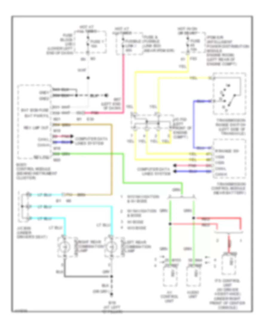
EXTERIOR LIGHTS
Backup Lamps Wiring Diagram for Nissan Altima S 2014
List of elements for Backup Lamps Wiring Diagram for Nissan Altima S 2014:
- (under right front of center console)
- 71j
- Audio unit
- Av control unit
- B19 (at left "c" pillar)
- Backup
- Bat bcm fuse
- Bat pwr f/l
- Body control module (behind instrument cluster)
- Can h
- Can l
- Can-h
- Can-l
- Computer data
- Computer data lines system
- E30
- F83
- Fuse & fusible link box (near ipdm e/r)
- Fuse 1 10a
- Fuse 10a
- Fuse block (j/b) (lower left end of dash)
- Fusible link i 40a
- Gnd1
- Gnd2
- Hot at all times
- Hot in on or start
- Ipdm e/r (intelligent power distribution module engine room) (left rear of engine compt)
- Its control unit (w/ driver assistance)
- J/c b06 (under driver's seat)
- J/c f02 (left front of engine compt)
- Left rear combination lamp
- Lines system
- M153
- M18
- M19
- M20
- M21
- M44
- M46
- M57 (left end of dash)
- M58
- M97
- Pnk
- R p
- R range sw
- Red
- Rev
- Rev lmp out
- Rev sig
- Right rear combination backup lamp
- Transmission control module (near battery)
- Transmission range switch (left side of transaxle)
- Vign
- W/ bose
- W/ navigation & bose
- W/o bose
- W/o navigation & w/ bose
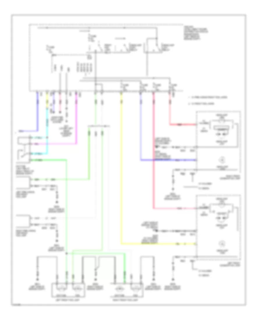
Exterior Lamps Wiring Diagram (1 of 2) for Nissan Altima S 2014
List of elements for Exterior Lamps Wiring Diagram (1 of 2) for Nissan Altima S 2014:
- (w/ information display) unified meter control unit
- 13p
- As door sw
- B13
- B19 (at left "c" pillar)
- Bat bcm fuse
- Bat pwr f/l
- Body control module (bcm) (behind instrument cluster)
- Brake sw lamp
- Buzzer
- Can-h
- Can-l
- Combi sw in 1
- Combi sw in 2
- Combi sw in 3
- Combi sw in 4
- Combi sw in 5
- Combi sw out 1
- Combi sw out 2
- Combi sw out 3
- Combi sw out 4
- Combi sw out 5
- Combination meter
- Combination switch (lighting & turn signal switch)
- Computer data lines system
- Dr door sw
- E15 (lower left rear of engine compt)
- E30
- Fl flasher
- Fr flasher
- Fuse & fusible link box (near ipdm e/r)
- Fuse 10a
- Fuse 5a
- Fuse block (j/b) (lower left end of dash)
- Fusible link i 40a
- Gnd1
- Hazard sw
- Hazard switch
- High mounted stop lamp (w/ rear spoiler)
- High mounted stop lamp (w/o rear spoiler)
- Hot at all times
- Hot in on or start
- Input 1
- Input 2
- Input 3
- Input 4
- Input 5
- Interior lights system
- Joint connector b07 (left front of luggage compt)
- Joint connector e10 (left end of dash)
- Left door mirror (if equipped)
- Left license plate lamp
- Left turn ind
- M112
- M17
- M18
- M19
- M20
- M21
- M24
- M57 (left end of dash)
- M61 (right end of dash)
- Output 1
- Output 2
- Output 3
- Output 4
- Output 5
- Pnk
- Red
- Right license plate lamp
- Right turn ind
- Rl door sw
- Rl flasher
- Rr door sw
- Rr flasher
- Side light & headlight
- Stop lamp relay (in fuse & fusible link box)
- Stop light switch (top of brake pedal assembly)
- Tan
Exterior Lamps Wiring Diagram (2 of 2) for Nissan Altima S 2014
List of elements for Exterior Lamps Wiring Diagram (2 of 2) for Nissan Altima S 2014:
- (if equipped) right door mirror
- (right side of engine compt) e209
- 2.5l
- 3.5l
- 72j
- 73j
- Abs actuator & electric unit (control unit) (right rear of engine compt)
- Abs/tcs/vdc control unit
- B19 (at left "c" pillar)
- Backup
- Backup lamps circuit
- Bls
- Computer data lines system
- Cpu
- D114 m84
- E15 (lower left rear of engine compt)
- E16
- E18
- E201
- E202 e2
- E204 (left side of engine compt)
- E217
- E224
- E235
- E236
- E29 b10
- E31
- E32
- E350 e233
- E351
- E63
- Engine control module (near battery)
- Fuse 10a
- Fusible link box (battery) (on battery positive (+) post)
- Fusible link c 80a
- Hot at all times
- Ipdm e/r (intelligent power distribution module engine room) (left rear of engine compt)
- J/c e08 (left end of dash)
- Left front combination lamp
- Left rear combination lamp
- M1 e30
- M6 b1
- M61 (right end of dash)
- Parking
- Pnk
- Right front combination lamp
- Right rear combination lamp
- Side marker
- Stop
- Stop lp sw
- Tail
- Tail lamp relay
- Turn signal
- W/ front fog lamps
- W/o front fog lamps
GROUND DISTRIBUTION
Ground Distribution Wiring Diagram (1 of 2) for Nissan Altima S 2014
List of elements for Ground Distribution Wiring Diagram (1 of 2) for Nissan Altima S 2014:
- (2.5l), air fuel ratio (a/f) sensor (bank 1) shield (3.5l), air fuel ratio (a/f) sensor (bank 2) shield (3.5l), electronic throttle control actuator shield (3.5l), ecm & cooling fan relay 2
- E15 (lower left rear of engine compt)
- E204 (left side of engine compt)
- E209 (right side of engine compt)
- E9 (lower left rear of engine compt)
- Horn (high) (w/ dual tone horn), right pre-wiring for front fog lamp, left front combination lamp, cooling fan motor 2, right front fog lamp, left front fog lamp, right front combination lamp & horn (low)
- Intake manifold runner control valve motor shield
- Intake manifold tuning valve motor shield (2.5l),
- Left front combination lamp, washer fluid level switch, left front fog lamp, right front combination lamp, right front fog lamp, hood switch/pre-wiring for hood switch & left pre-wiring for front fog lamp
- M57 (left end of dash)
- M61 (right end of dash)
- Meter control switch, cvt shift selector, accessory relay 2, air bag diagnosis sensor unit, front passenger air bag off indicator, front air control, push-button ignition switch, av control unit (w/ navigation), heated steering wheel switch, hazard switch, its control unit, glove box lamp, vdc off switch, trunk lid opener switch, a/c switch assembly, right accessory prewire, a/c auto amp, dongle unit, left front heated seat switch, right front heated seat switch, combination switch, usb interface lamp, warning system switch, audio unit (w/o navigation), rear personal lamp, front room/map lamp assembly, right blind spot warning indicator, right power window & door lock/unlock switch, right front outside handle, diode 3, right door mirror & door mirror remote control switch
- Moonroof switch, fuse block (j/b), bcm (body control module), data link connector, door mirror remote control switch, combination meter, combination switch, blower motor, heated steering wheel switch, steering angle sensor, warning system switch, vdc off switch, trunk lid opener cancel switch, trunk lid opener switch, front power socket, left accessory prewire, paddle shifter (shift up), paddle shifter (shift down), front console power socket, left vanity mirror lamp, auto-dazzling inside mirror, right vanity mirror lamp, rear personal lamp, front room/map lamp assembly, moonroof motor assembly, left blind spot warning indicator, left door mirror, left front outside handle, left front door lock assembly & main power window & door lock/unlock switch
- Stop lamp relay, ipdm e/r (intelligent power distribution module engine room), brake fluid level switch, front wiper motor, cooling fan relay 3, a/c compressor, primary speed sensor, output speed sensor, tcm (transmission control module) & input speed sensor
Ground Distribution Wiring Diagram (2 of 2) for Nissan Altima S 2014
List of elements for Ground Distribution Wiring Diagram (2 of 2) for Nissan Altima S 2014:
- Abs actuator & electric unit (control unit)
- B107 (right "b" pillar)
- B117 (right "c" pillar)
- B19 (at left "c" pillar)
- B58 (under left rear of vehicle)
- B7 (left "b" pillar)
- Bose speaker amp
- Condenser & ignition coils 1, 2, 3 & 4 (w/ power transistor) ignition coils 5 & 6 (w/ power transistor) (3.5l)
- E33 (right rear of engine compt)
- E61 (right rear of engine compt)
- F15 (2.5l: top front of engine) (3.5l: front of left cylinder bank)
- F9 (2.5l: top front of engine) (3.5l: front of left cylinder bank)
- Left rear power window switch, trunk lamp switch & trunk release solenoid, trunk opener request switch, right license plate lamp, power seat switch, lumbar support switch (w/ power lumbar support), fuel level sensor unit & fuel pump, left rear combination lamp, left license plate lamp, right rear combination lamp, rear view camera washer control unit, high mounted stop lamp & left front seat heater
- Left seat belt buckle switch
- Power steering control module
- Rear window defogger
- Right front seat heater, right seat belt buckle switch, occupant classification system control unit & right rear power window switch
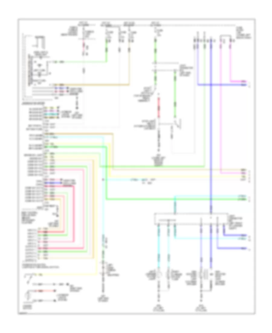
HEADLIGHTS
Headlights Wiring Diagram (1 of 2) for Nissan Altima S 2014
List of elements for Headlights Wiring Diagram (1 of 2) for Nissan Altima S 2014:
- 12g
- 13p
- 77j
- 78j
- A/l pwr sply 5v
- A/l signal
- As door sw
- B104
- Bat
- Bat bcm fuse
- Bat pwr f/l
- Bcm (body control module) (behind instrument cluster)
- Brake ind
- Can-h
- Can-l
- Combi sw in 1
- Combi sw in 2
- Combi sw in 3
- Combi sw in 4
- Combi sw in 5
- Combi sw out 1
- Combi sw out 2
- Combi sw out 3
- Combi sw out 4
- Combi sw out 5
- Combination meter
- Combination switch (lighting & turn signal switch)
- Computer data lines system
- Dr door sw
- E30
- Fog light ind
- Fuse 10a
- Fuse 5a
- Fuse block (j/b) (lower left end of dash)
- Fuse/fusible link & relay box (near ipdm e/r)
- Fusible link box (battery) (on battery positive (+) post)
- Fusible link c 80a
- Fusible link i 40a
- Gnd rf a/l
- Gnd1
- Gnd2
- Headlight (green) ind
- Hot at all times
- Hot w/ ignition relay 2 energized
- Ign
- Input 1
- Input 2
- Input 3
- Input 4
- Input 5
- Left front door switch (in left "b" pillar)
- Left rear door switch (in left "c" pillar)
- M10
- M17
- M18
- M19
- M21
- M24
- M28
- M57 (left end of dash)
- Optical sensor (top right side of dash, near base of right "a" pillar)
- Output 1
- Output 2
- Output 3
- Output 4
- Output 5
- Parking brake switch (top of parking brake lever)
- Pkb sw
- Pnk
- Red
- Right front door switch (in right "b" pillar)
- Right rear door switch (in right "c" pillar)
- Rl door sw
- Rr door sw
- Tan
- Unified meter control unit (w/ information display)
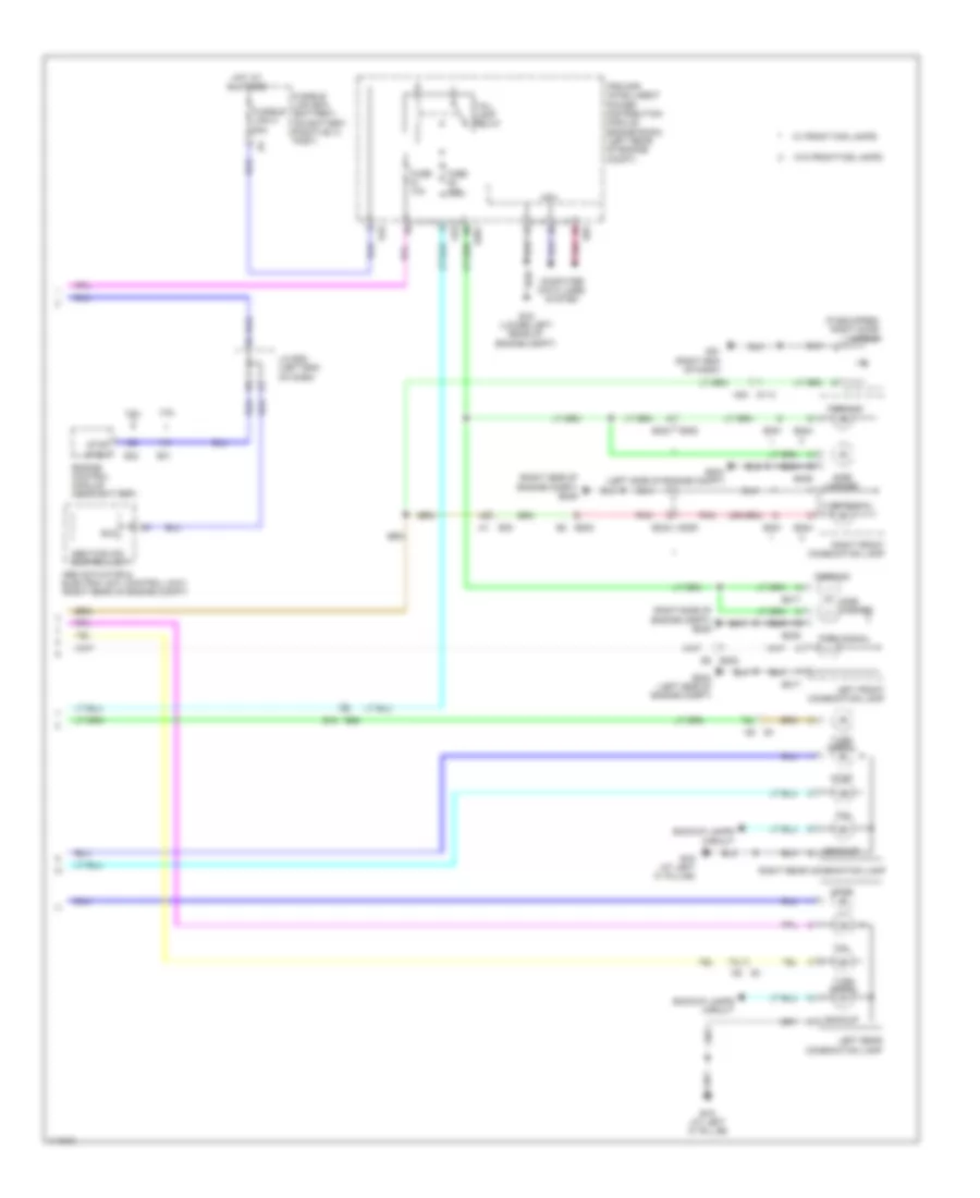
Headlights Wiring Diagram (2 of 2) for Nissan Altima S 2014
List of elements for Headlights Wiring Diagram (2 of 2) for Nissan Altima S 2014:
- (left side of engine compt) (w/ halogen) e204
- (left side of engine compt) (w/ xenon) e204
- 10a
- Can-h
- Can-l
- Computer data lines system
- Cpu
- Daytime
- Daytime light relay (right front of engine compt)
- Dtrl rly
- E15 (lower left rear of engine compt)
- E16
- E18
- E200
- E201
- E202
- E204 (left side of engine compt)
- E209 (right side of engine compt)
- E209 (w/ halogen) (right side of engine compt)
- E209 (w/ xenon) (right side of engine compt)
- E212
- E213
- E222
- E223
- E231
- E232
- E240
- E243
- E301
- E305
- E63
- Fog
- Front fog lamp relay
- Fuse
- Fuse 10a
- Fuse 15a
- Gnd
- Hdlp hi
- Hdlp lo
- Headlamp high
- Headlamp high relay
- Headlamp low
- Headlamp low relay
- Hid cont
- Ipdm e/r (intelligent power distribution module engine room) (left rear of engine compt)
- Left front combination lamp
- Left front fog lamp
- Left pre wiring for front fog lamp
- Pnk
- Red
- Right front combination lamp
- Right front fog lamp
- Right pre wiring for front fog lamp
- Rly fog
- W/ front fog lamps
- W/ halogen
- W/ pre wiring front fog lamps
- W/ xenon
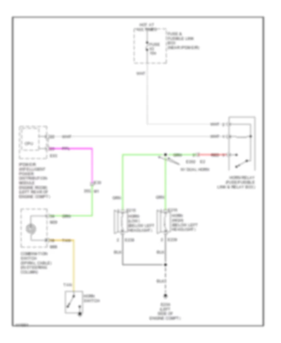
HORN
Horn Wiring Diagram for Nissan Altima S 2014
List of elements for Horn Wiring Diagram for Nissan Altima S 2014:
- 35g m1
- Combination switch (spiral cable) (in steering column)
- Cpu
- E202
- E204 (left side of engine compt)
- E215
- E216
- E238
- E239
- E30
- E63
- Fuse & fusible link box (near ipdm e/r)
- Fuse 15a
- Horn (high) (below left headlight)
- Horn (low) (below left headlight)
- Horn relay (fuse/fusible link & relay box)
- Horn switch
- Hot at all times
- Ipdm e/r (intelligent power distribution module engine room) (left rear of engine compt)
- M29
- M88
- Red
- Tan
- W/ dual horn
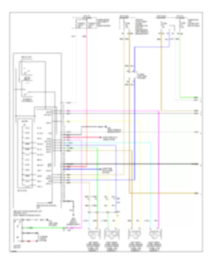
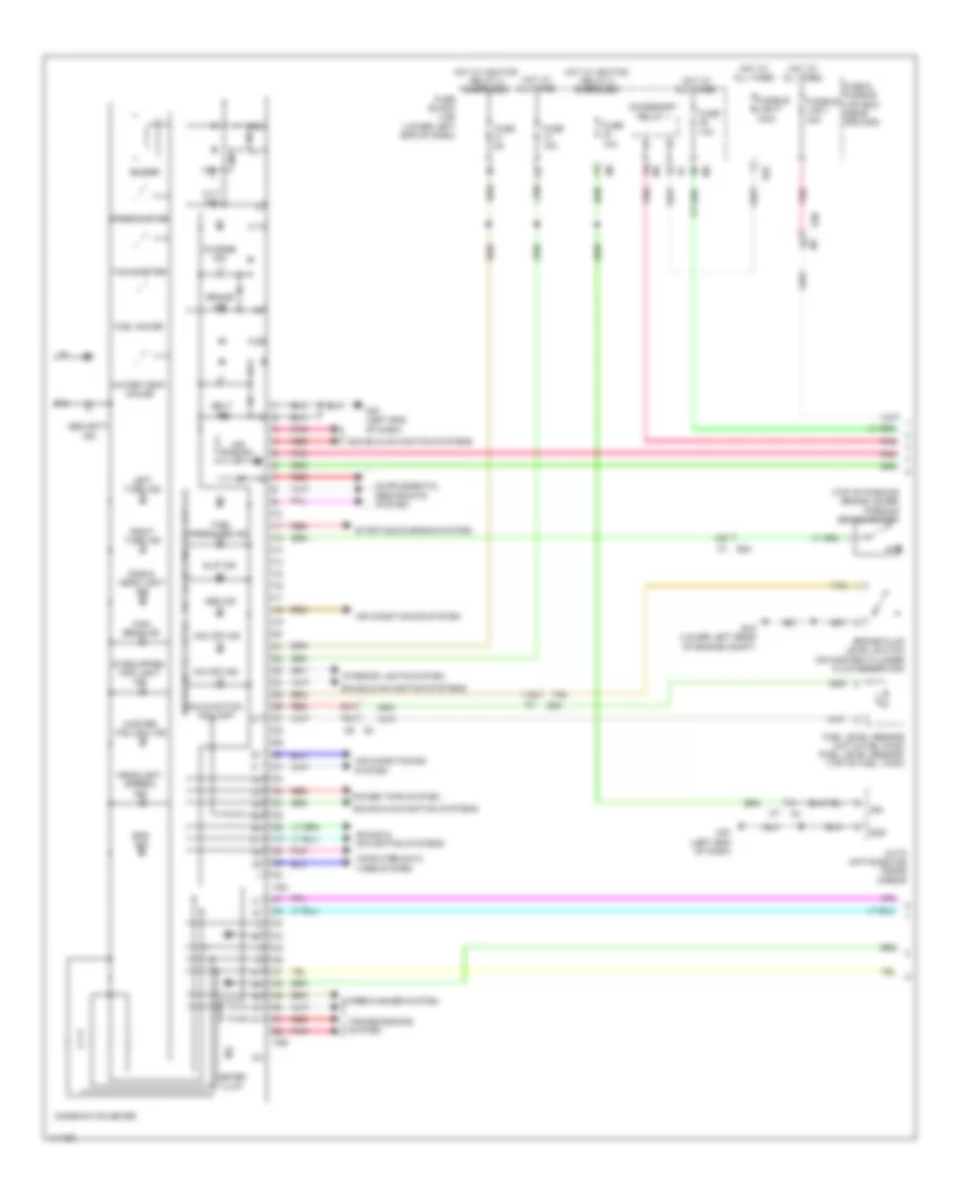
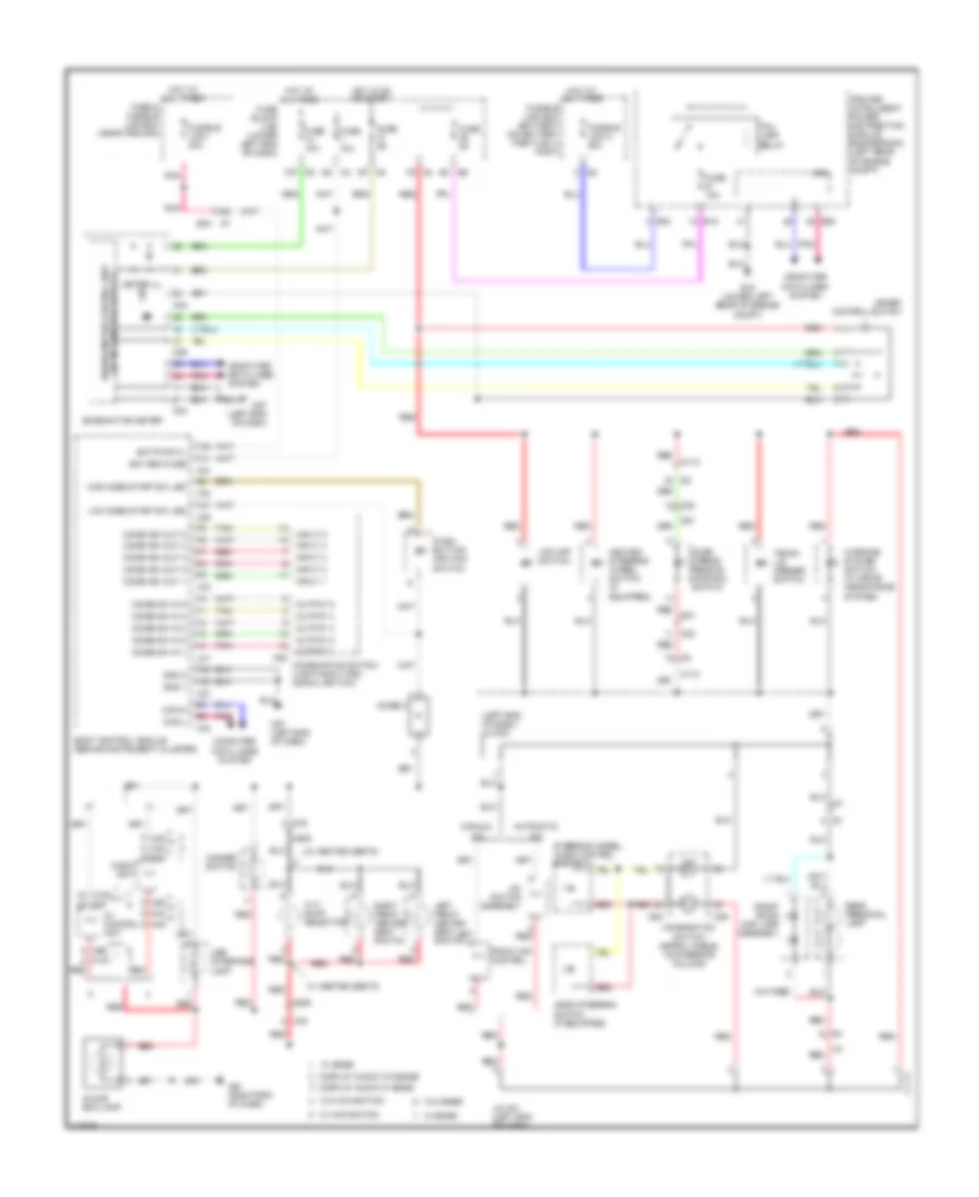
INSTRUMENT CLUSTER
Instrument Cluster Wiring Diagram (1 of 2) for Nissan Altima S 2014
List of elements for Instrument Cluster Wiring Diagram (1 of 2) for Nissan Altima S 2014:
- (if equipped) fog light ind
- (top of parking brake lever) parking brake switch
- 11g
- 12g
- 13p
- 79j
- 80j
- Abs ind
- Accessory relay 1
- Air bag ind
- Air conditioning system
- Auto anti-dazzling inside mirror
- Belt ind
- Brake fluid level switch (on master cylinder fluid reservoir)
- Brake ind
- Buzzer
- Charge ind
- Combination meter
- Computer data lines system
- Cvt ind
- E15 (lower left rear of engine compt)
- E30
- E62
- Eps ind
- Fuel gauge
- Fuel level sensor unit & fuel pump (fuel level sensor) (top of fuel tank)
- Fuse & fusible link box (near ipdm e/r)
- Fuse 10a
- Fuse 5a
- Fuse block (j/b) (lower left end of dash)
- Fusible link f 100a
- Fusible link i 40a
- Gnd
- Headlight (green) ind
- High beam ind
- Hot at all times
- Hot w/ ignition relay 2 energized
- Ign
- Interior lights system
- Left turn ind
- M24
- M26
- M57 (left end of dash)
- Malfunction ind lamp
- Meter illum
- O/d off ind
- Pnk
- Power tops system
- Red
- Right turn ind
- Security ind
- Side & head light ind
- Slip ind
- Sound & navigation systems
- Speedometer
- Starting/charging system
- Tachometer
- Tan
- Tire pressure ind
- Transmissions system
- Unified meter control unit (w/ information display)
- Vdc off ind
- Water temp gauge
- Wiper/washer system
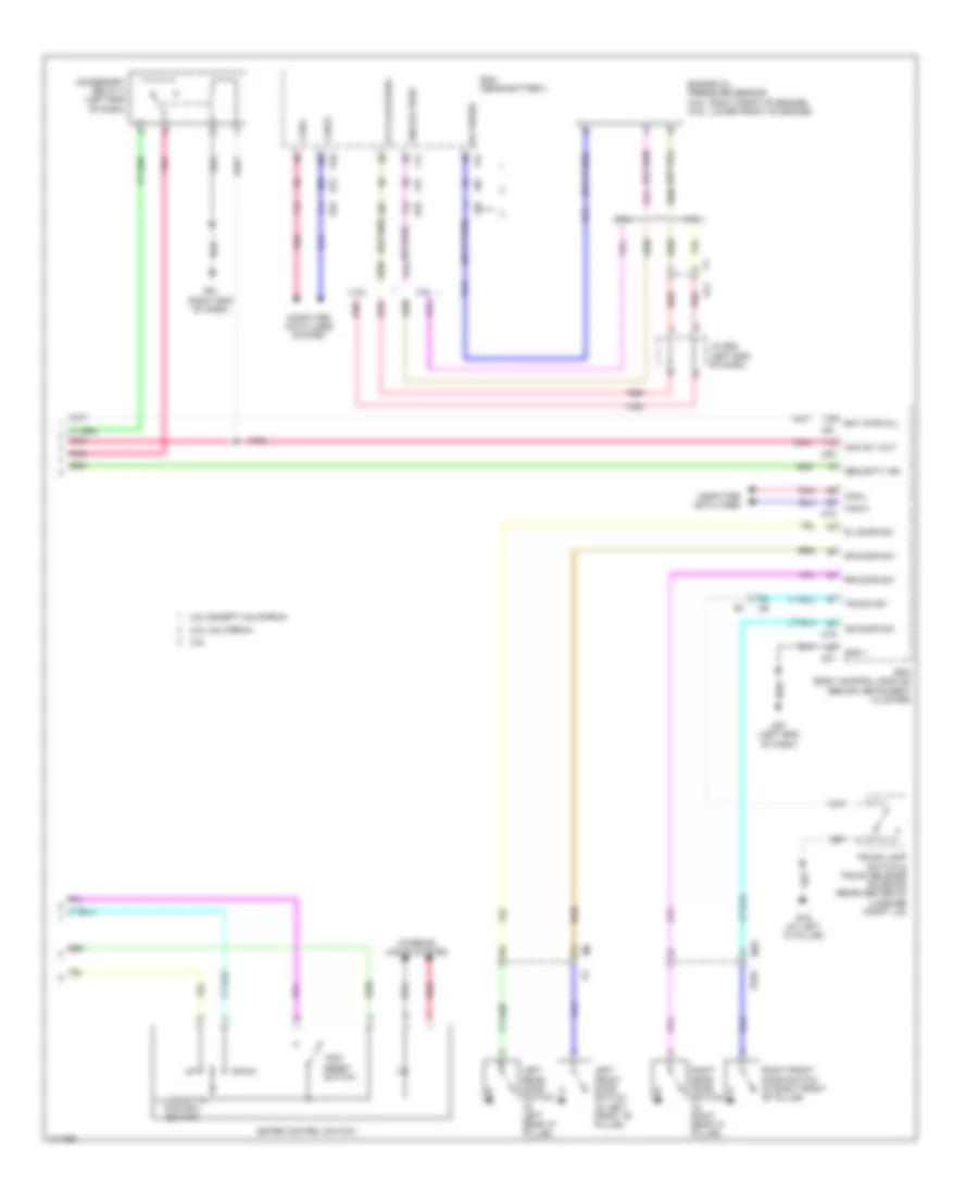
Instrument Cluster Wiring Diagram (2 of 2) for Nissan Altima S 2014
List of elements for Instrument Cluster Wiring Diagram (2 of 2) for Nissan Altima S 2014:
- (or pnk)
- (or red)
- 2.5l
- 2.5l california
- 2.5l except california
- 3.5l
- 76j
- 77j
- 78j
- Acc rly out
- Accessory relay 2 (left end of dash)
- As door sw
- Av cc2-oilpres
- B104
- B19 (at left "c" pillar)
- Bat pwr (f/l)
- Bcm (body control module) (behind instrument cluster)
- Can-h
- Can-l
- Computer data lines
- Computer data lines system
- Down
- Dr door sw
- E10
- E11
- E31
- E32
- Ecm (near battery)
- Engine oil pressure sensor (2.5l: right front of engine) (3.5l: lower front of engine)
- F14
- F78
- F91
- Gnd 1
- Gnd-oil pres
- Illumination control switch
- Interior lights system
- J/c e08 (left end of dash)
- Left front door switch (in left front "b" pillar)
- Left rear door switch (in left rear "c" pillar)
- M10
- M18
- M19
- M20
- M21
- M57 (left end of dash)
- M61 (right end of dash)
- Meter control switch
- Oil press
- Pnk
- Red
- Right front door switch (in right front "b" pillar)
- Right rear door switch (in right rear "c" pillar)
- Rl door sw
- Rr door sw
- Security ind
- Trip reset switch
- Trunk lamp switch & trunk release solenoid (rear center of luggage compt lid)
- Trunk sw
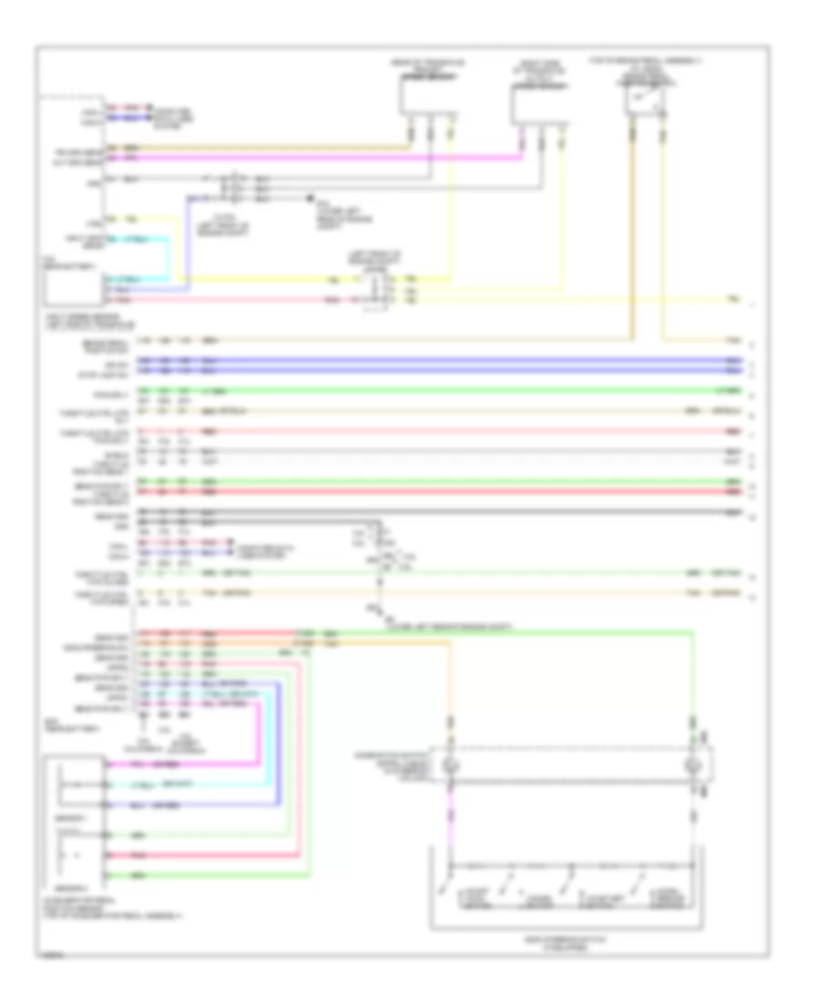
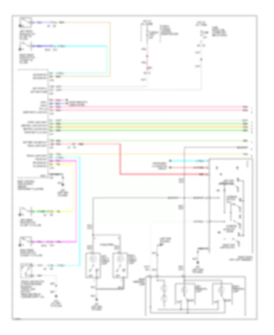
INTERIOR LIGHTS
Courtesy Lamps Wiring Diagram (1 of 2) for Nissan Altima S 2014
List of elements for Courtesy Lamps Wiring Diagram (1 of 2) for Nissan Altima S 2014:
- (left end of dash)
- 76j
- 77j
- 78j
- As door sw
- B104
- B19 (at left "c" pillar)
- Bat bcm fuse
- Bat pwr f/l
- Battery saver out
- Body control module (bcm) (behind instrument cluster)
- Can-h
- Can-l
- Central lock switch
- Central unlock sw
- Computer data lines system
- Door
- Door key/c lock sw
- Door key/c ulk sw
- Dr door sw
- E30
- Front room/ map lamp assembly
- Fuse & fusible link box (near ipdm e/r)
- Fuse 10a
- Fuse block (j/b) (lower left end of dash)
- Fusible link i 40a
- Gnd 1
- Hot at all times
- If equipped
- Instrument illumination circuit
- Interior switch (all)
- Interior switch (door)
- Left front door switch (in left "b" pillar)
- Left map lamp switch
- Left personal lamp
- Left rear door switch (in left "c" pillar)
- Left vanity mirror lamp
- M1 5g
- M10
- M17
- M18
- M19
- M21
- M57
- M57 (left end of dash)
- Off
- Pnk
- Pw lin
- Rear personal lamp
- Red
- Right front door switch (in right "b" pillar)
- Right map lamp switch
- Right personal lamp
- Right rear door switch (in right "c" pillar)
- Right vanity mirror lamp
- Rl door sw
- Room lamp cont
- Rr door sw
- Step lamp cont
- Tan
- Trunk lamp cont
- Trunk lamp switch & trunk release solenoid (trunk lamp switch) (rear center of luggage compt lid)
- Trunk sw
Courtesy Lamps Wiring Diagram (2 of 2) for Nissan Altima S 2014
List of elements for Courtesy Lamps Wiring Diagram (2 of 2) for Nissan Altima S 2014:
- 74j
- 75j
- Between full stroke & n
- Cpu
- D114
- Full stroke
- Key cylinder switch
- Left front door lock assembly
- Left front step lamp
- Lock
- Lock switch
- M11
- M112
- M57 (left end of dash)
- M61 (right end of dash)
- M84
- Main power window & door lock/unlock switch (w/ left & right front power window anti-pinch system)
- Main power window & door lock/unlock switch (w/ left front power window anti-pinch system)
- Pnk
- Red
- Right front step lamp
- Right power window & door lock/unlock switch (w/ left & right front power window anti-pinch system)
- Right power window & door lock/unlock switch (w/ left front power window anti-pinch system)
- Tan
- Trunk room lamp
- Un lock
- Unlock
- Unlock switch
- W/ left & right front power window anti-pinch system
- W/ left front power
- Window anti-pinch system
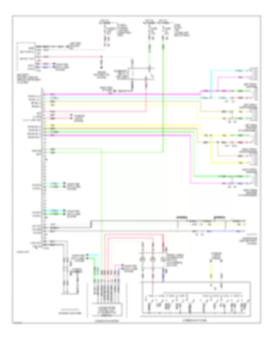
Instrument Illumination Wiring Diagram for Nissan Altima S 2014
List of elements for Instrument Illumination Wiring Diagram for Nissan Altima S 2014:
- (left end of dash) j/c m02
- (right end of dash)
- 13p m5
- 1r m4
- 6m e6
- A/c switch assembly
- Ascd steering switch (if equipped)
- Audio unit
- Automatic a/c
- Av ill- control unit ill+
- Bat bcm fuse
- Bat pwr f/l
- Body control module (behind instrument cluster)
- Can-h
- Can-l
- Combi sw in 1
- Combi sw in 2
- Combi sw in 3
- Combi sw in 4
- Combi sw in 5
- Combi sw out 1
- Combi sw out 2
- Combi sw out 3
- Combi sw out 4
- Combi sw out 5
- Combination meter
- Combination switch (lighting & turn signal switch)
- Combination switch (spiral cable) (in steering column)
- Computer data lines system
- Cpu
- Cvt shift selector
- D30
- D51
- Diode 3
- Display audio w/ bose
- Display audio w/o bose
- Door mirror remote control switch
- E15 (lower left rear of engine compt)
- E16
- E18
- E30
- E63
- Front air ill- control
- Front room/ map lamp assembly
- Fuse & fusible link box (near ipdm e/r)
- Fuse 10a
- Fuse 5a
- Fuse block (j/b) (lower left end of dash)
- Fusible link box (battery) (on battery positive (+) post)
- Fusible link c 80a
- Fusible link i 40a
- Glove box lamp
- Gnd 1
- Gnd 2
- Hazard switch
- Heated steering wheel switch (if equipped)
- High side start sw led
- Hot at all times
- Hot in on or start
- Ill+
- Ill-
- Input 1
- Input 2
- Input 3
- Input 4
- Input 5
- Ipdm e/r (intelligent power distribution module engine room) (left rear of engine compt)
- J/c m01 (left end of dash)
- Left front heated seat switch
- Low side start sw led
- M112
- M151 red
- M153
- M16
- M17
- M18
- M20
- M205
- M21
- M24
- M26
- M28
- M29
- M3 6n
- M43
- M45
- M5 8p
- M57 (left end of dash)
- M61
- M85
- M88
- M96
- M97
- Manual a/c
- Meter control switch
- Meter ill
- Output 1
- Output 2
- Output 3
- Output 4
- Output 5
- Pnk
- Push- button ignition
- Rear personal lamp
- Red
- Right front heated seat switch
- Steering wheel audio control switch
- Switch
- Tail lamp relay
- Tan
- Trunk lid opener switch
- Unified meter control unit (w/ information display)
- Usb interface lamp
- Vdc off switch
- W/ base
- W/ bose
- W/ heated seats
- W/ navigation
- W/o bose
- W/o navigation
- Warning system switch (w/ drive assistance system)
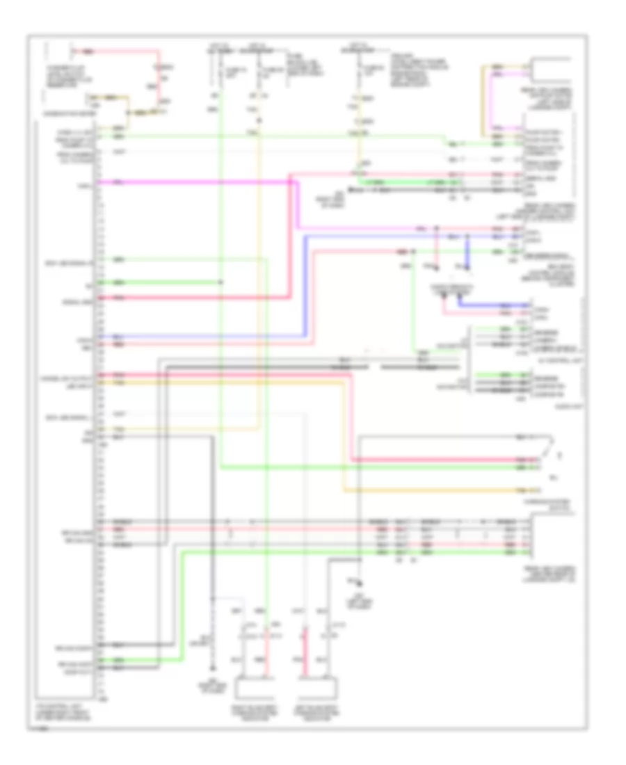
NAVIGATION
Driver Assistance Wiring Diagram for Nissan Altima S 2014
List of elements for Driver Assistance Wiring Diagram for Nissan Altima S 2014:
- 1g m1
- 2g m1
- 51j
- 52j
- 53j
- 54j
- 55j
- 65j
- 66j
- 67j
- Audio unit
- Av control unit
- Bcm (body control module) (behind instrument cluster)
- Camera (shield)
- Camera+
- Can-h
- Can-l
- Cancel sw output
- Combination meter
- Comp out+
- Composite+
- Composite-
- Computer data lines system
- D101
- D114
- E2 tan
- E200
- E202
- E30
- From camera c/u to pump
- From pump to camera c/u
- Fuse 15 20a
- Fuse 29 5a
- Fuse 50 10a
- Fuse block (j/b) (lower left end of dash)
- Gnd
- Hot at all times
- Hot in on or start
- Ign
- Ipdm e/r (intelligent power distribution module engine room) (left rear of engine compt)
- Its control unit (under right front of center console)
- Led input
- Left blind spot warning system indicator
- M112
- M14
- M151
- M153
- M18
- M20
- M26
- M46
- M57 (left end of dash)
- M58
- M59
- M61 (right end of dash)
- M84
- Pnk
- Pump motor +
- Pump motor -
- Rear view camera (center rear of luggage compt lid)
- Rear view camera air pump motor (left side of luggage compt)
- Rear view camera washer control unit (left side of luggage compt)
- Red
- Rev
- Reverse
- Reverse signal
- Right blind spot warning system indicator
- Rr cam comp+
- Rr cam cont
- Rr cam gnd
- Rr cam on
- Serial gnd
- Shield
- Signal gnd
- Sow led signal l
- Sow led signal r
- Tan
- W/ navigation
- W/o navigation
- Warning system switch
- Wash lvl sw
- Washer fluid level switch (in washer fluid reservoir)
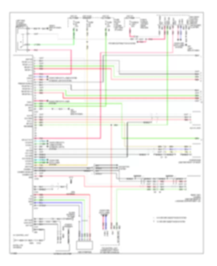
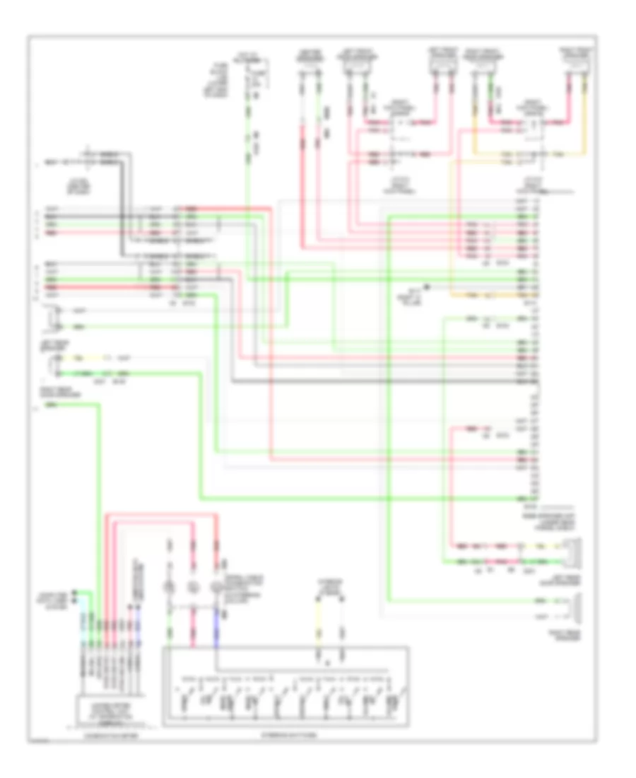
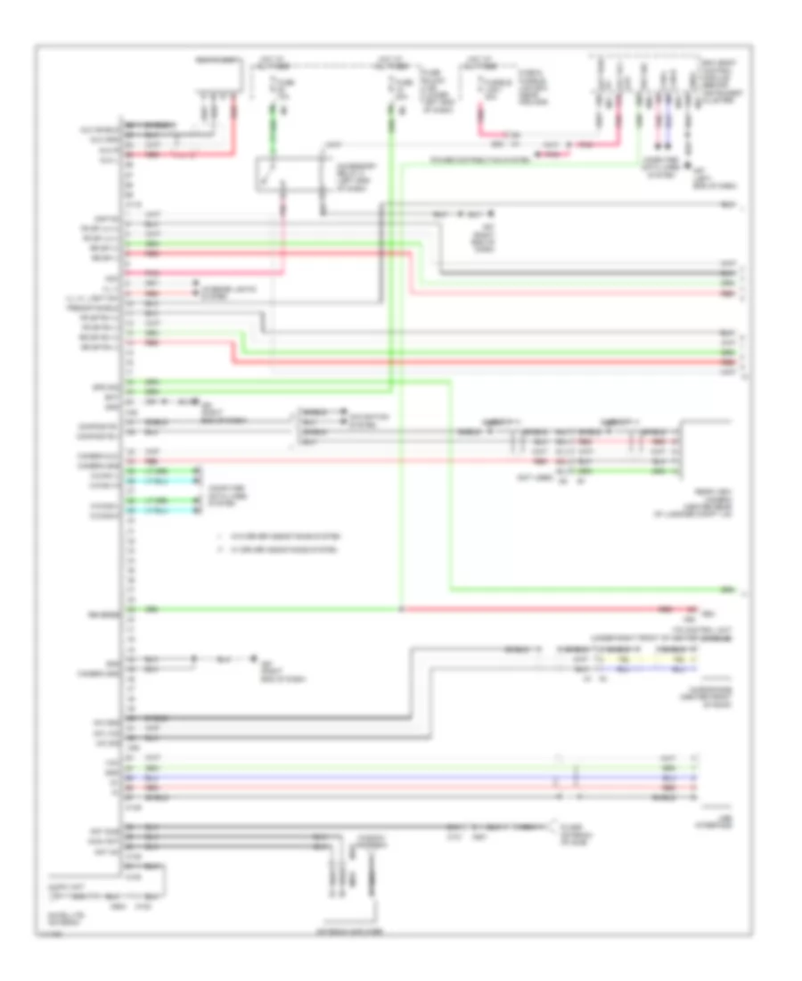
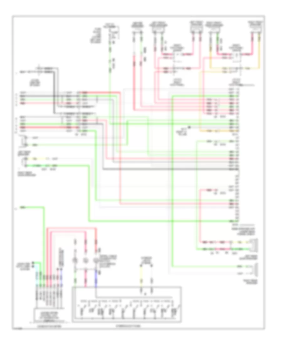
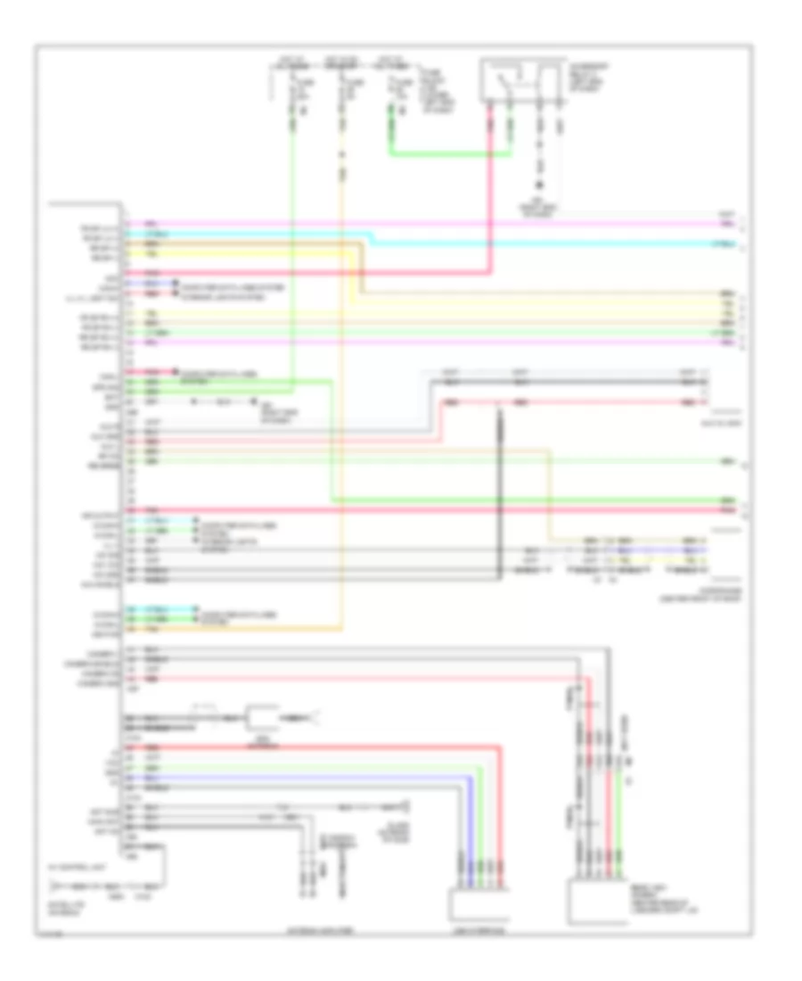
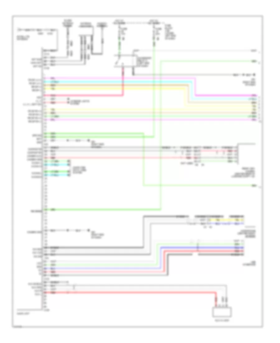
Navigation Wiring Diagram, with Bose (1 of 2) for Nissan Altima S 2014
List of elements for Navigation Wiring Diagram, with Bose (1 of 2) for Nissan Altima S 2014:
- (left end of dash) accessory relay 2
- (right end of dash) m61
- 51j
- 52j
- 53j
- 54j
- 55j
- Acc
- Acc rly out
- Amp on
- Ant on
- Ant sub
- Antenna amplifier
- Aux gnd
- Aux in jack
- Aux l
- Aux r
- Aux shield
- Av control unit
- Bat
- Bat pwr f/l m21
- Bcm (body control module) (behind instrument cluster)
- Bf mic
- Camera (shield)
- Camera +
- Camera on
- Can-h
- Can-l
- Computer data lines system
- E30
- Fr sp lh (+)
- Fr sp lh (-)
- Fr sp rh (+)
- Fr sp rh (-)
- Fuse & fusible link box (near ipdm e/r)
- Fuse 10a
- Fuse 20a
- Fuse 5a
- Fuse block (j/b) (lower left end of dash)
- Fusible link i 40a
- Glass antenna (fm sub)
- Gnd
- Gnd2
- Gps antenna
- Hot at all times
- Hot in on or start
- Ignition
- Ill (+)
- Ill-
- Interior lights system
- Its control unit (under right front of center console)
- M-can-h
- M-can-l
- M100
- M101
- M102
- M131
- M137
- M151
- M153
- M18
- M20
- M21
- M500
- M501
- M57 (left end of dash)
- M59
- M61 (right end of dash)
- M99
- Main ant
- Mic gnd
- Mic sig
- Mic vcc
- Microphone (center front of roof)
- Mr out put
- Navigation system
- Nca
- Pnk
- Power distribution system
- Preamp shield
- Put mr out
- Rear view camera (center rear of luggage compartment lid)
- Red
- Rev
- Rev sig
- Reverse
- Rr cam cont
- Rr sp (+)
- Rr sp (-)
- Rr sp rh (+)
- Rr sp rh (-)
- Satellite antenna
- Shield
- Spd sig
- Tan
- Usb interface
- Vcc
- W/ driver assistance system
- W/o driver assistance system
- Window antenna
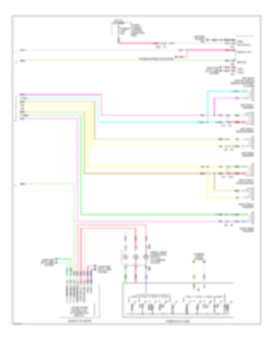
Navigation Wiring Diagram, with Bose (2 of 2) for Nissan Altima S 2014
List of elements for Navigation Wiring Diagram, with Bose (2 of 2) for Nissan Altima S 2014:
- (right kick panel) j/c m11
- (right kick panel) j/c m13
- 100j
- 14p
- 99j
- B102
- B103
- B106
- B109
- B110
- B117 (right "c" pillar)
- Back
- Bose speaker amp (under rear parcel shelf)
- Can-h
- Can-l
- Center speaker
- Combination meter
- Computer data lines system
- D1 m11
- D101 m14
- D201
- D301
- Display
- Down menu
- Down volume
- Enter
- Fuse 20a
- Fuse block (j/b) (lower left end of dash)
- Hot at all times
- Ill+
- Ill-
- Interior lights system
- J/c m04 (center of dash)
- J/c m10 (right kick panel)
- J/c m12 (right kick panel)
- Left front door speaker
- Left front speaker
- Left rear door speaker
- Left rear speaker
- M-can-h
- M-can-l
- M30
- M300
- M50
- M88
- M9 b103
- Off tel
- On tel
- Pnk
- Red
- Right front door speaker
- Right front speaker
- Right rear door speaker
- Right rear speaker
- Shield
- Source
- Spd 8p/r
- Spiral cable (combination switch) (in steering column)
- Steering switches
- Strg sw gnd
- Strg sw ip1
- Strg sw ip2
- Tan
- Unified meter control unit (w/ information display)
- Up menu
- Up volume
Navigation Wiring Diagram, without Bose (1 of 2) for Nissan Altima S 2014
List of elements for Navigation Wiring Diagram, without Bose (1 of 2) for Nissan Altima S 2014:
- (not used)
- 51j
- 52j
- 53j
- 54j
- 55j
- Acc
- Accessory relay 2 (left end of dash)
- Ant on
- Ant sub
- Antenna amplifier
- Aux gnd
- Aux in jack
- Aux l
- Aux r
- Aux shield
- Av control unit
- Bat
- Bf mic
- Camera +
- Camera gnd
- Camera on
- Camera-(shield)
- Can-h
- Can-l
- Computer data lines system
- Fr sp lh (+)
- Fr sp lh (-)
- Fr sp rh (+)
- Fr sp rh (-)
- Fuse 10a
- Fuse 20a
- Fuse 5a
- Fuse block (j/b) (lower left end of dash)
- Glass antenna (fm sub)
- Gnd
- Gps antenna
- Hot at all times
- Hot in on or start
- Ignition
- Ill (+), light sw
- Ill (-)
- Interior lights system
- M-can-h
- M-can-l
- M101
- M102
- M103
- M134
- M500
- M501
- M61 (right end of dash)
- M93
- M96
- M97
- M98
- Main ant
- Mic gnd
- Mic sig
- Mic vcc
- Microphone (center front of roof)
- Mr output
- Nca
- Pnk
- Rear view camera (center rear of luggage compt lid)
- Red
- Reverse
- Rr sp (+)
- Rr sp (-)
- Rr sp rh (+)
- Rr sp rh (-)
- Satellite antenna
- Shield
- Spd sig
- Tan
- Usb interface
- Vcc
- Window antenna
Navigation Wiring Diagram, without Bose (2 of 2) for Nissan Altima S 2014
List of elements for Navigation Wiring Diagram, without Bose (2 of 2) for Nissan Altima S 2014:
- Acc rly out
- Back
- Bat pwr f/l m21
- Bcm (body control module) (behind instrument cluster)
- Can-h
- Can-l
- Combination meter
- Computer data lines system
- D101
- Display
- Down menu
- Down volume
- E30
- Enter
- Fuse & fusible link box (near ipdm e/r)
- Fusible link i 40a
- Gnd2
- Hot at all times
- Left front door speaker
- Left front speaker
- Left rear speaker
- M-can-h
- M-can-l
- M11
- M14
- M18
- M20
- M21
- M30
- M57 (left end of dash)
- M88
- Off tel
- On tel
- Output mr
- Pnk
- Power distribution system
- Red
- Rev sig
- Right front door speaker
- Right front speaker
- Right rear speaker
- Source
- Spd 8p/r
- Spiral cable (combination switch) (in steering column)
- Steering switches
- Strg sw gnd
- Strg sw ip1
- Strg sw ip2
- Unified meter control unit (w/ information display)
- Up menu
- Up volume
POWER DISTRIBUTION
Power Distribution Wiring Diagram (1 of 3) for Nissan Altima S 2014
List of elements for Power Distribution Wiring Diagram (1 of 3) for Nissan Altima S 2014:
- (on battery positive (+) post) fusible link box (battery)
- Air conditioning & cooling fans systems
- Anti-lock brakes system
- Battery
- Cpu
- Door locks system
- E16
- E17
- E18
- E201
- E62
- Electronic power steering system
- Exterior lights system
- From a/c relay (diagram 2 of 3)
- Front fog lamp relay
- Front wiper high relay
- Front wiper relay
- Fuse & fusible link box (near ipdm e/r)
- Fuse (canada) 10a
- Fuse 10a
- Fuse 15a
- Fuse 30a
- Fusible link a 250a
- Fusible link b 100a
- Fusible link c 80a
- Fusible link d 100a
- Fusible link e 80a
- Fusible link f 100a
- Fusible link g 40a
- Fusible link h 40a
- Fusible link i 40a
- Fusible link l 40a
- Fusible link m 40a
- Fusible link n 40a
- Headlamp high relay
- Headlamp low relay
- Headlights system
- Horns system
- Ipdm e/r (intelligent power distribution module engine room) (left rear of engine compt)
- Pnk
- Power windows, door locks, instrument cluster, wiper/washer, headlights, shift interlock, anti-theft, defogger, interior lights, power tops, trunk, tailgate, fuel doors, exterior lights, seats, transmissions, sound & body computer systems
- Red
- Starter relay
- Starting/ charging system
- Tail lamp relay
- Tan
- To fuse block (j/b) (diagram 2 of 3)
- To fuse block (j/b) (diagram 3 of 3)
- To intelligent power distribution module engine room (ipdm e/r) (diagram 2 of 3)
- Transmissions system
- Wiper/ washer system
Power Distribution Wiring Diagram (2 of 3) for Nissan Altima S 2014
List of elements for Power Distribution Wiring Diagram (2 of 3) for Nissan Altima S 2014:
- (information not available)
- (left rear of engine compt) ipdm e/r (intelligent power distribution module engine room)
- 12r
- 13p
- 13r
- 14p
- 16r
- A/c relay
- Accessory relay 1
- Air conditioning & cooling fans systems
- Air conditioning & seats systems
- Anti-lock brakes & electronic power steering systems
- Anti-lock brakes system
- Anti-theft, door locks & body computer systems
- Cooling fan relay 1
- Cpu
- Door locks system
- E15 (lower left rear of engine compt)
- E16
- E18
- E200
- E63
- Engine controls system
- Engine controls, door locks, power windows, wiper/washer, headlights, exterior lights, computer data lines, anti-theft, warning, interior lights, mirrors, power tops & body computer systems
- Extended storage switch
- F83
- F84
- From bcm (diagram 3 of 3)
- From fusible link box (battery) (diagram 1 of 3)
- Front console power socket
- Front power socket
- Fuel pump relay
- Fuse 10a
- Fuse 15a
- Fuse 20a
- Fuse 5a
- Fuse block (j/b) (lower left end of dash)
- Ignition relay 1
- M16
- M205
- M57 (left end of dash)
- Navigation & sound
- Pnk
- Red
- Seats system
- Systems
- To accessory relay 2 (diagram 3 of 3)
- To front wiper high relay (diagram 1 of 3)
- To fuse 10 (diagram 3 of 3)
- To fuse 16 (diagram 3 of 3)
- To fuse 56 (diagram 3 of 3)
- To push button ignition switch (diagram 3 of 3)
- Transmissions system
- Wiper/ washer & navigation systems
Power Distribution Wiring Diagram (3 of 3) for Nissan Altima S 2014
List of elements for Power Distribution Wiring Diagram (3 of 3) for Nissan Altima S 2014:
- (diagram 2 of 3)
- (right end of dash) m61
- 10r
- 13r
- 16p
- 37g
- Acc led
- Acc rly out
- Acc/on
- Accessory relay 2 (left end of dash)
- Air conditioning & engine controls systems
- Air conditioning system
- Air conditioning, instrument cluster, defogger, mirrors & seats systems
- Air conditioning, instrument cluster, mirrors, navigation & sound systems
- B13
- Bcm (body control module) (behind instrument cluster)
- Bwr fan rly out
- Cpu
- Defogger system
- Door locks system
- E18
- E30
- Ecm relay
- Engine controls system
- Engine controls, computer data lines, navigation & transmissions systems
- Engine controls, cruise control, door locks, exterior lights, shift interlock & anti-theft systems
- F83
- F84
- From bcm (diagram 3 of 3)
- From fuse & fusible link box (diagram 1 of 3)
- From fuse 12 (diagram 2 of 3)
- From fuse 4 f (diagram 2 of 3)
- From fuse block (j/b) l (diagram 2 of 3)
- From fuse block g (j/b) (diagram 2 of 3)
- From ignition relay 1 h
- Front blower motor relay
- Fuse 10a
- Fuse 15a
- Fuse 5a
- Fuse block (j/b) (lower left end of dash)
- Fuse brake sw
- Ign ele rly out 2 m18
- Ignition relay 2
- Illu- mination
- Interior lights system
- Ipdm e/r (intelligent power distribution module engine room) (left rear of engine compt)
- M17
- M20
- M57 (left end of dash)
- M61 (right end of dash)
- Pnk
- Push button ignition switch
- Push switch
- Rear window defogger relay
- Red
- Red eng strt sw no escl
- Rr def rly
- Seats system
- Shorting input m17
- Tan
- Throttle control motor relay
- To accessory relay 2 (diagram 3 of 3)
- To fuse block (j/b) (diagram 2 of 3)
POWER DOOR LOCKS
Power Door Locks Wiring Diagram (1 of 4) for Nissan Altima S 2014
List of elements for Power Door Locks Wiring Diagram (1 of 4) for Nissan Altima S 2014:
- (left end of dash) m57
- +5v sply
- 10r
- 13g
- 15g
- 4n m3
- 5m e6
- 76j
- 85j
- 86j m6
- 8m e6
- Acc led
- As door ant a
- As door ant b
- As door switch
- As request switch
- At device out
- Audio dongle
- Bat bcm fuse
- Bat front door
- Bat power f/l
- Bat rear door
- Bat saver out
- Bcm (body control module) (behind instrument cluster)
- Brake sw fuse
- Brake sw lamp
- Buzzer out
- Can-h
- Can-l
- Central lock switch
- Central unlock switch
- Computer data lines system
- Dongle unit (canada) (upper center of dash)
- Door key/c lock switch
- Door key/c unlock switch
- Door lock dr/as/fl
- Door lock rr/rl
- Door unlock as
- Door unlock dr/fl
- Dr door ant a
- Dr door ant b
- Dr door lock status
- Dr door switch
- Dr request switch
- Dr unlock rr/rl
- E15 (lower left rear of engine compt)
- E30
- Eng start switch no escl
- Exterior lights system
- Fl flasher
- Fr flasher
- Fuse & fusible link box
- Fuse 10a
- Fuse 15a
- Fuse block (j/b) (lower left end of dash)
- Fusible link i 40a
- Gnd
- Gnd rf a/l
- Gnd1
- Gnd2
- Hazard switch
- Hot at all times
- Ign usm out 1
- Intelligent key warning buzzer (left rear of engine compt)
- Interior lights system
- J/c e10 (left end of dash)
- M17
- M18
- M19
- M20
- M21
- M4 9r
- M61 (right end of dash)
- Pnk
- Pw lin
- Rear bumper ant a
- Rear bumper ant b
- Rear bumper antenna (behind center of rear bumper)
- Red
- Rf nimoco
- Rl door switch
- Room ant 2 a
- Room ant 2 b
- Room lamp cont
- Rr door switch
- Security ind
- Shift n/p
- Shift p
- Starter relay out
- Stop lamp relay (fuse/fusible link & relay box)
- Stop light switch
- Tan
- Trunk ant 3 a
- Trunk ant 3 b
- Trunk open sw
- Trunk request switch
- Trunk switch
- Trunk, tailgate, fuel doors system
Power Door Locks Wiring Diagram (2 of 4) for Nissan Altima S 2014
List of elements for Power Door Locks Wiring Diagram (2 of 4) for Nissan Altima S 2014:
- (if equipped)
- 31g
- 36g m1
- Computer data lines system
- Cpu
- Cvt shift selector (if equipped)
- D101
- D114
- E15 (lower left rear of engine compt)
- E18
- E201
- E30
- E63
- F10
- F83
- F84
- Front console antenna (under rear of center console)
- Fuse 10a
- Headlights system
- Horns system
- Hot at all times
- Ignition relay 1
- Ipdm e/r (intelligent power distribution module engine room) (left rear of engine compt)
- J/c e08 (left end of dash)
- Left front outside handle
- M1 37g
- M112
- M14
- M57 (left end of dash)
- M61 (right end of dash)
- M84
- Outside key antenna
- Park position switch
- Pnk
- Red
- Request switch
- Right front outside handle
- Starter control relay
- Starter relay
- Starting/ charging system
- Tan
Power Door Locks Wiring Diagram (3 of 4) for Nissan Altima S 2014
List of elements for Power Door Locks Wiring Diagram (3 of 4) for Nissan Altima S 2014:
- 77j m6
- 83j
- 84j
- 87j
- B104
- B19 (at left "c" pillar)
- E209 (right side of engine compt)
- Hood switch or pre-wireing for hood switch (center front engine compt)
- J/c f02 (left front of engine compt)
- Left front door switch (in left "b" pillar)
- Left rear door switch (at left "c" pillar)
- M10
- M6 78j
- Pnk
- Rear parcel shelf antenna (under center of rear parcel shelf)
- Red
- Right front door switch (in right "b" pillar)
- Right rear door switch (at right "c" pillar)
- Tan
- Transmission range switch (left side of transaxle)
- Trunk lamp switch & trunk release solenoid (rear center of trunk lid)
- Trunk opener request switch
Power Door Locks Wiring Diagram (4 of 4) for Nissan Altima S 2014
List of elements for Power Door Locks Wiring Diagram (4 of 4) for Nissan Altima S 2014:
- 12r m4
- 13p m5
- 97j
- Acc/on
- Actuator
- B104
- B106
- Between full stroke & n
- Buzzer
- Combination meter
- Computer data lines system
- Cpu
- D101
- D114
- D201
- D301
- Door unlock sensor
- Full stroke
- Fuse 10a
- Fuse 5a
- Fuse block (j/b) (lower left end of dash)
- Hot at all times
- Illumi- nation
- Interior lights system
- Key cylinder switch
- Key ind
- Left front door lock assembly
- Left rear door lock actuator
- Lock
- Lock switch
- M10
- M11
- M11 d1
- M112
- M14
- M24
- M57 (left end of dash)
- M6 98j
- M61 (right end of dash)
- M84
- Main power window & door lock/unlock switch (w/ left & right front power window anti-pinch system)
- Main power window & door lock/unlock switch (w/ left front power window anti-pinch system)
- Pnk
- Push button ignition switch
- Push switch
- Red
- Remote keyless entry receiver (upper right end of dash)
- Right front door lock actuator
- Right power window & door lock/unlock switch (w/ left & right front power window anti-pinch system)
- Right power window & door lock/unlock switch (w/ left front power window anti-pinch system)
- Right rear door lock actuator
- Security ind
- Tan
- Un lock
- Unified meter control unit (w/ information display)
- Unlock
- Unlock switch
- W/ left & right front power window anti-pinch system
- W/ left front power
- Window anti-pinch system
POWER MIRRORS
Auto Anti-dazzling Inside Mirror Wiring Diagram, with Homelink Universal Transceiver for Nissan Altima S 2014
List of elements for Auto Anti-dazzling Inside Mirror Wiring Diagram, with Homelink Universal Transceiver for Nissan Altima S 2014:
- 7p m5
- Auto anti-dazzling inside mirror
- Batt+
- Fuse 10a
- Fuse block (j/b) (lower left end of dash)
- Gnd
- Hot at all times
- Hot w/ ignition relay 2 energized
- Ign
- M3 6n
- M57 (left end of dash)
Auto Anti-dazzling Inside Mirror Wiring Diagram, without Homelink Universal Transceiver for Nissan Altima S 2014
List of elements for Auto Anti-dazzling Inside Mirror Wiring Diagram, without Homelink Universal Transceiver for Nissan Altima S 2014:
- Auto anti-dazzling inside mirror
- Fuse 10a
- Fuse block (j/b) (lower left end of dash)
- Gnd
- Hot w/ ignition relay 2 energized
- Ign
- M57 (left end of dash)
Power Mirrors Wiring Diagram for Nissan Altima S 2014
List of elements for Power Mirrors Wiring Diagram for Nissan Altima S 2014:
- (right end of dash) m61
- Acc rly out
- Accessory relay-2 (left end of dash)
- Body control module (bcm) (behind instrument cluster)
- D114
- D2 m112
- D30 d51
- D51 d30
- Defogger & exterior lights systems
- Defogger system
- Door mirror remote control switch
- Down
- Exterior lights system
- Fuse 25 10a
- Fuse block (j/b) (lower left end of dash)
- Hot at all times
- Illumination
- Interior lights system
- Left
- Left door mirror
- M112
- M184
- M20
- M57 (left end of dash)
- Mirror defogger
- Mirror switch
- Off
- Pnk
- Red
- Right
- Right door mirror
- Select switch
- Tan
- Turn signal
POWER SEATS
Driver Power Seat Wiring Diagram for Nissan Altima S 2014
List of elements for Driver Power Seat Wiring Diagram for Nissan Altima S 2014:
- (at left "c" pillar) b19
- 5g m1
- B12 b201
- B19 (at left "c" pillar)
- Bat
- Body control module (bcm) (behind instrument cluster)
- Bwd
- Down
- E30
- Front lifting motor
- Front lifting switch
- Fuse & fusible link box (near ipdm e/r)
- Fusible link i 40a
- Fwd
- Gnd1
- Gnd2
- Hot at all times
- Lumbar support motor
- Lumbar support switch (if equipped)
- M21
- M57 (left end of dash)
- M6 b1
- P/w
- Pnk
- Power seat switch
- Rear lifting motor
- Rear lifting switch
- Reclining motor
- Reclining switch
- Red
- Sliding motor
- Sliding switch
Heated Seats Wiring Diagram for Nissan Altima S 2014
List of elements for Heated Seats Wiring Diagram for Nissan Altima S 2014:
- B107 (right "b" pillar)
- B12
- B128
- B19 (at left "c" pillar)
- B201
- B305
- Fuse 15a
- Fuse block (j/b) (lower left end of dash)
- Hot w/ ignition relay 2 energized
- Illumination
- Interior lights system
- Left front heated seat switch
- Left front seat heater
- Left seat back heater
- Left seat cushion heater
- M10
- M16
- M205
- M6 7j
- M61 (right end of dash)
- Red
- Right front heated seat switch
- Right front seat heater
- Right seat back heater
- Right seat cushion heater
- Thermo- stat
Heated Steering Wheel Wiring Diagram for Nissan Altima S 2014
List of elements for Heated Steering Wheel Wiring Diagram for Nissan Altima S 2014:
- A/c auto amp (behind a/c switch assembly)
- Batt
- Fuse 10a
- Fuse 5a
- Fuse block (j/b) (lower left end of dash)
- Gnd
- Heated steering relay (left end of dash)
- Heated steering wheel
- Heated steering wheel switch
- Hot at all times
- Hot w/ ignition relay 2 energized
- Ign
- Illum
- Interior lights system
- M52
- M57 (left end of dash)
- M61 (right end of dash)
- On indicator
- P-gnd
- Pnk
- Red
- Spiral cable (combination switch) (in steering column)
- Strg htr rly
- Strg htr sw
- Tan
- Thermostat
POWER TOP/SUNROOF
Power Top/Sunroof Wiring Diagram for Nissan Altima S 2014
List of elements for Power Top/Sunroof Wiring Diagram for Nissan Altima S 2014:
- 77j
- As door sw
- B104
- Bat bcm fuse
- Bat pwr f/l
- Batt
- Bcm (body control module) (behind instrument cluster)
- Can-h
- Can-l
- Car speed
- Close/up sw
- Combination meter
- Computer data lines system
- Dn/ open
- Dr door sw
- E30
- Fuse 10a
- Fuse block (j/b) (lower left end of dash)
- Fuse/fusible link & relay box (near ipdm e/r)
- Fusible link i 40a
- Gnd
- Gnd1
- Gnd2
- Hot at all times
- Ign
- Left front door switch (in left front "b" pillar)
- M10
- M13
- M18
- M19
- M21
- M24
- M57 (left end of dash)
- Moonroof motor assembly (center front of roof)
- Moonroof switch
- Open/down sw
- P/w pwr sply bat
- P/w pwr sply ign
- Pnk
- R10
- R11
- Red
- Right front door switch (in right front "b" pillar)
- Speed 2p/r
- Unified meter control unit (w/ information display)
- Up/ close
POWER WINDOWS
Power Windows Wiring Diagram, with Driver & Passenger Side Anti-Pinch System (1 of 2) for Nissan Altima S 2014
List of elements for Power Windows Wiring Diagram, with Driver & Passenger Side Anti-Pinch System (1 of 2) for Nissan Altima S 2014:
- 93j
- 94j
- As door switch
- Bat
- Bat power f/l
- Between full stroke & n
- Body control module (bcm) (behind instrument cluster)
- Can-h
- Can-l
- Com
- Computer data lines system
- Cpu
- D2 m112
- Dr door switch
- Dr down
- Dr up
- Encoder
- Encoder +
- Encoder gnd
- Encoder sig1
- Encoder sig2
- Full stroke
- Fuse & fusible link box (near ipdm e/r)
- Fusible link i 40a
- Gnd
- Gnd1
- Hot at all times
- Ign
- Left front door lock assembly (key cylinder switch)
- Left front power window motor
- Left rear
- Lock
- Lock switch
- Lr down
- Lr up
- M1 e30
- M11
- M11 d1
- M112 d2
- M18
- M19
- M21
- M57 (left end of dash)
- Main power window & door lock/unlock switch
- P/w pwr sply ign
- Pnk
- Power window lock switch
- Pw lin
- Red
- Right rear
- Rr down
- Rr up
- Tan
- Un lock
- Unlock
- Unlock switch
Power Windows Wiring Diagram, with Driver & Passenger Side Anti-Pinch System (2 of 2) for Nissan Altima S 2014
List of elements for Power Windows Wiring Diagram, with Driver & Passenger Side Anti-Pinch System (2 of 2) for Nissan Altima S 2014:
- 77j
- 92j
- B104
- B107 (right "b" pillar)
- B19 (at left "c" pillar)
- Bat
- Com
- Cpu
- D101
- D114
- D201 b6
- D301 b106
- Down
- Encoder
- Gnd
- Illumination
- Joint connector b02 (under rear of center console)
- Left front door switch (in left "b" pillar)
- Left rear power window motor
- Left rear power window switch
- Lock
- M10
- M14
- M61 (right end of dash)
- M84
- Pnk
- Power
- Red
- Right front door switch (in right "b" pillar)
- Right front power window motor
- Right power window & door lock/ unlock switch
- Right rear power window motor
- Right rear power window switch
- Sig1
- Sig2
- Tan
- Unlock
Power Windows Wiring Diagram, with Driver Side Anti-Pinch System (1 of 2) for Nissan Altima S 2014
List of elements for Power Windows Wiring Diagram, with Driver Side Anti-Pinch System (1 of 2) for Nissan Altima S 2014:
- (behind instrument cluster) body control module
- (left end of dash)
- 77j
- As door switch
- As down
- As up
- B104
- Bat
- Bat power f/l
- Can-h
- Can-l
- Central dr lock sw
- Central dr unlock sw
- Computer data lines system
- Cpu
- D12
- Dr door switch
- Dr down
- Dr up
- E30
- Encoder
- Encoder +
- Encoder gnd
- Encoder sig1
- Encoder sig2
- Fuse & fusible link box (near ipdm e/r)
- Fusible link i 40a
- Gnd
- Gnd1
- Hot at all times
- Ign
- Left front door switch (in left "b" pillar)
- Left front power window motor
- Left rear
- Lock
- Lock sw
- Lock switch
- M10
- M11
- M17
- M18
- M19
- M21
- M57
- M57 (left end of dash)
- Main power window & door lock/unlock switch
- Pnk
- Power window lock switch
- Red
- Right front
- Right front door switch (in right "b" pillar)
- Right rear
- Rl down
- Rl up
- Rr down
- Rr up
- Tan
- Un lock sw
- Unlock
Power Windows Wiring Diagram, with Driver Side Anti-Pinch System (2 of 2) for Nissan Altima S 2014
List of elements for Power Windows Wiring Diagram, with Driver Side Anti-Pinch System (2 of 2) for Nissan Altima S 2014:
- 92j
- 93j
- 94j
- B104
- B106
- B107 (right "b" pillar)
- B19 (at left "c" pillar)
- D101
- D114
- D201
- D301
- Illumination
- Joint connector b02 (under rear of center console)
- Left rear power window motor
- Left rear power window switch
- Lock
- M10
- M14
- M61 (right end of dash)
- M84
- Right front power window motor
- Right power window & door lock/unlock switch
- Right rear power window motor
- Right rear power window switch
- Switch lock
- Tan
- Unlock
RADIO
Radio Wiring Diagram, Base for Nissan Altima S 2014
List of elements for Radio Wiring Diagram, Base for Nissan Altima S 2014:
- (left end of dash) m57
- (right end of dash) m61
- Acc
- Acc rly out
- Accessory relay 2 (left end of dash)
- Ant on
- Antenna amplifier
- Audio unit
- Back
- Bat
- Bat pwr f/l
- Bcm (body control module) (behind instrument cluster)
- Can-h
- Can-l
- Combination meter
- Computer data lines system
- D101
- Display
- Down menu
- Down volume
- E30 m1
- Enter
- Fr sp lh (+)
- Fr sp lh (-)
- Fr sp rh (+)
- Fr sp rh (-)
- Fuse & fusible link box (near ipdm e/r)
- Fuse 10a
- Fuse 20a
- Fuse block (j/b) (lower left end of dash)
- Fusible link i 40a
- Gnd2
- Hot at all times
- Ill (+), light sw
- Ill gnd
- Ill+
- Ill-
- Interior lights system
- Left front door speaker
- Left front speaker
- Left rear speaker (w/ 6 speakers)
- M-can-h
- M-can-l
- M101
- M11
- M138
- M14
- M18
- M20
- M21
- M30
- M501
- M85
- M86
- M87
- M88
- Main ant
- Mic gnd
- Mic sig
- Mic vcc
- Microphone (center front of roof)
- Nca
- Off tel
- On tel
- Pnk
- Power distribution system
- Red
- Right front door speaker
- Right front speaker
- Right rear speaker (w/ 6 speakers)
- Rr sp (+)
- Rr sp (-)
- Rr sp rh (+)
- Rr sp rh (-)
- Shield
- Source
- Spd 8p/r
- Spd sig
- Spiral cable (combination switch) (in steering column)
- Steering switches
- Strg sw gnd
- Strg sw ip1
- Strg sw ip2
- Unified meter control unit (w/ information display)
- Up menu
- Up volume
- Window antenna
Radio Wiring Diagram, with Bose with Navigation (1 of 2) for Nissan Altima S 2014
List of elements for Radio Wiring Diagram, with Bose with Navigation (1 of 2) for Nissan Altima S 2014:
- (left end of dash) accessory relay 2
- (right end of dash) m61
- 51j
- 52j
- 53j
- 54j
- 55j
- Acc
- Acc rly out
- Amp on
- Ant on
- Ant sub
- Antenna amplifier
- Aux gnd
- Aux in jack
- Aux l
- Aux r
- Aux shield
- Av control unit
- Bat
- Bat pwr f/l m21
- Bcm (body control module) (behind instrument cluster)
- Bf mic
- Camera (shield)
- Camera +
- Camera on
- Can-h
- Can-l
- Computer data lines system
- E30
- Fr sp lh (+)
- Fr sp lh (-)
- Fr sp rh (+)
- Fr sp rh (-)
- Fuse & fusible link box (near ipdm e/r)
- Fuse 10a
- Fuse 20a
- Fuse 5a
- Fuse block (j/b) (lower left end of dash)
- Fusible link i 40a
- Glass antenna (fm sub)
- Gnd
- Gnd2
- Gps antenna
- Hot at all times
- Hot in on or start
- Ignition
- Ill (+)
- Ill-
- Interior lights system
- Its control unit (under right front of center console)
- M-can-h
- M-can-l
- M100
- M101
- M102
- M131
- M137
- M151
- M153
- M18
- M20
- M21
- M500
- M501
- M57 (left end of dash)
- M59
- M61 (right end of dash)
- M99
- Main ant
- Mic gnd
- Mic sig
- Mic vcc
- Microphone (center front of roof)
- Mr out put
- Navigation system
- Nca
- Pnk
- Power distribution system
- Preamp shield
- Put mr out
- Rear view camera (center rear of luggage compartment lid)
- Red
- Rev
- Rev sig
- Reverse
- Rr cam cont
- Rr sp (+)
- Rr sp (-)
- Rr sp rh (+)
- Rr sp rh (-)
- Satellite antenna
- Shield
- Spd sig
- Tan
- Usb interface
- Vcc
- W/ driver assistance system
- W/o driver assistance system
- Window antenna
Radio Wiring Diagram, with Bose with Navigation (2 of 2) for Nissan Altima S 2014
List of elements for Radio Wiring Diagram, with Bose with Navigation (2 of 2) for Nissan Altima S 2014:
- (right kick panel) j/c m11
- (right kick panel) j/c m13
- 100j
- 14p
- 99j
- B102
- B103
- B106
- B109
- B110
- B117 (right "c" pillar)
- Back
- Bose speaker amp (under rear parcel shelf)
- Can-h
- Can-l
- Center speaker
- Combination meter
- Computer data lines system
- D1 m11
- D101 m14
- D201
- D301
- Display
- Down menu
- Down volume
- Enter
- Fuse 20a
- Fuse block (j/b) (lower left end of dash)
- Hot at all times
- Ill+
- Ill-
- Interior lights system
- J/c m04 (center of dash)
- J/c m10 (right kick panel)
- J/c m12 (right kick panel)
- Left front door speaker
- Left front speaker
- Left rear door speaker
- Left rear speaker
- M-can-h
- M-can-l
- M30
- M300
- M50
- M88
- M9 b103
- Off tel
- On tel
- Pnk
- Red
- Right front door speaker
- Right front speaker
- Right rear door speaker
- Right rear speaker
- Shield
- Source
- Spd 8p/r
- Spiral cable (combination switch) (in steering column)
- Steering switches
- Strg sw gnd
- Strg sw ip1
- Strg sw ip2
- Tan
- Unified meter control unit (w/ information display)
- Up menu
- Up volume
Radio Wiring Diagram, with Bose without Navigation (1 of 2) for Nissan Altima S 2014
List of elements for Radio Wiring Diagram, with Bose without Navigation (1 of 2) for Nissan Altima S 2014:
- (not used)
- 51j
- 52j
- 53j
- 54j
- 55j
- Acc
- Acc rly out
- Accessory relay 2 (left end of dash)
- Amp on
- Ant on
- Ant sub
- Antenna amplifier
- Audio unit
- Aux gnd
- Aux in jack
- Aux l
- Aux r
- Aux shield
- Bat
- Bat pwr f/l m21
- Bcm (body control module) (behind instrument cluster)
- Camera 6.2v
- Camera gnd
- Can-h
- Can-l
- Composite +
- Composite -
- Computer data lines system
- E30
- Fr sp lh (+)
- Fr sp lh (-)
- Fr sp rh (+)
- Fr sp rh (-)
- Fuse & fusible link box (near ipdm e/r)
- Fuse 10a
- Fuse 20a
- Fuse block (j/b) (lower left end of dash)
- Fusible link i 40a
- Glass antenna (fm sub)
- Gnd
- Gnd2
- Hot at all times
- Ill (+), light sw
- Ill (-)
- Interior lights system
- Its control unit (under right front of center console)
- M-can1-h
- M-can1-l
- M-can2-h
- M-can2-l
- M101
- M102
- M105
- M119
- M139
- M149
- M18
- M20
- M21
- M45
- M46
- M500
- M501
- M57 (left end of dash)
- M58
- M61 (right end of dash)
- Main ant
- Mic gnd
- Mic sig
- Mic vcc
- Microphone (center front of roof)
- Navigation system
- Nca
- Pnk
- Power distribution system
- Preamp shield
- Rear view camera (center rear of luggage compt lid)
- Red
- Rev
- Rev sig
- Reverse
- Rr sp (+)
- Rr sp (-)
- Rr sp rh (+)
- Rr sp rh (-)
- Satellite antenna
- Shield
- Spd sig
- Usb interface
- Vcc
- W/ driver assistance system
- W/o driver assistance system
- Window antenna
Radio Wiring Diagram, with Bose without Navigation (2 of 2) for Nissan Altima S 2014
List of elements for Radio Wiring Diagram, with Bose without Navigation (2 of 2) for Nissan Altima S 2014:
- (right kick panel) j/c m11
- (right kick panel) j/c m13
- 100j
- 14p
- 99j
- B102
- B103
- B106
- B109
- B110
- B117 (right "c" pillar)
- Back
- Bose speaker amp (under rear parcel shelf)
- Can-h
- Can-l
- Center speaker
- Combination meter
- Computer data lines system
- D1 m11
- D101 m14
- D201
- D301
- Display
- Down menu
- Down volume
- Enter
- Fuse 20a
- Fuse block (j/b) (lower left end of dash)
- Hot at all times
- Ill+
- Ill-
- Interior lights system
- J/c m04 (center of dash)
- J/c m10 (right kick panel)
- J/c m12 (right kick panel)
- Left front door speaker
- Left front speaker
- Left rear door speaker
- Left rear speaker
- M-can-h
- M-can-l
- M30
- M300
- M50
- M88
- M9 b103
- Off tel
- On tel
- Pnk
- Red
- Right front door speaker
- Right front speaker
- Right rear door speaker
- Right rear speaker
- Shield
- Source
- Spd 8p/r
- Spiral cable (combination switch) (in steering column)
- Steering switches
- Strg sw gnd
- Strg sw ip1
- Strg sw ip2
- Tan
- Unified meter control unit (w/ information display)
- Up menu
- Up volume
Radio Wiring Diagram, without Bose with Navigation (1 of 2) for Nissan Altima S 2014
List of elements for Radio Wiring Diagram, without Bose with Navigation (1 of 2) for Nissan Altima S 2014:
- (not used)
- 51j
- 52j
- 53j
- 54j
- 55j
- Acc
- Accessory relay 2 (left end of dash)
- Ant on
- Ant sub
- Antenna amplifier
- Aux gnd
- Aux in jack
- Aux l
- Aux r
- Aux shield
- Av control unit
- Bat
- Bf mic
- Camera +
- Camera gnd
- Camera on
- Camera-(shield)
- Can-h
- Can-l
- Computer data lines system
- Fr sp lh (+)
- Fr sp lh (-)
- Fr sp rh (+)
- Fr sp rh (-)
- Fuse 10a
- Fuse 20a
- Fuse 5a
- Fuse block (j/b) (lower left end of dash)
- Glass antenna (fm sub)
- Gnd
- Gps antenna
- Hot at all times
- Hot in on or start
- Ignition
- Ill (+), light sw
- Ill (-)
- Interior lights system
- M-can-h
- M-can-l
- M101
- M102
- M103
- M134
- M500
- M501
- M61 (right end of dash)
- M93
- M96
- M97
- M98
- Main ant
- Mic gnd
- Mic sig
- Mic vcc
- Microphone (center front of roof)
- Mr output
- Nca
- Pnk
- Rear view camera (center rear of luggage compt lid)
- Red
- Reverse
- Rr sp (+)
- Rr sp (-)
- Rr sp rh (+)
- Rr sp rh (-)
- Satellite antenna
- Shield
- Spd sig
- Tan
- Usb interface
- Vcc
- Window antenna
Radio Wiring Diagram, without Bose with Navigation (2 of 2) for Nissan Altima S 2014
List of elements for Radio Wiring Diagram, without Bose with Navigation (2 of 2) for Nissan Altima S 2014:
- Acc rly out
- Back
- Bat pwr f/l m21
- Bcm (body control module) (behind instrument cluster)
- Can-h
- Can-l
- Combination meter
- Computer data lines system
- D101
- Display
- Down menu
- Down volume
- E30
- Enter
- Fuse & fusible link box (near ipdm e/r)
- Fusible link i 40a
- Gnd2
- Hot at all times
- Left front door speaker
- Left front speaker
- Left rear speaker
- M-can-h
- M-can-l
- M11
- M14
- M18
- M20
- M21
- M30
- M57 (left end of dash)
- M88
- Off tel
- On tel
- Output mr
- Pnk
- Power distribution system
- Red
- Rev sig
- Right front door speaker
- Right front speaker
- Right rear speaker
- Source
- Spd 8p/r
- Spiral cable (combination switch) (in steering column)
- Steering switches
- Strg sw gnd
- Strg sw ip1
- Strg sw ip2
- Unified meter control unit (w/ information display)
- Up menu
- Up volume
Radio Wiring Diagram, without Bose without Navigation (1 of 2) for Nissan Altima S 2014
List of elements for Radio Wiring Diagram, without Bose without Navigation (1 of 2) for Nissan Altima S 2014:
- (not used)
- 51j
- 52j
- 53j
- 54j
- 55j
- Acc
- Accessory relay 2 (left end of dash)
- Amplifier
- Ant on
- Ant sub
- Antenna
- Audio unit
- Aux gnd
- Aux in jack
- Aux l
- Aux r
- Aux shield
- Bat
- Camera 6.2v
- Camera gnd
- Composite+
- Composite-
- Computer data lines system
- Fr sp lh (+)
- Fr sp lh (-)
- Fr sp rh (+)
- Fr sp rh (-)
- Fuse 10a
- Fuse 20a
- Fuse block (j/b) (lower left end of dash)
- Glass antenna (fm sub)
- Gnd
- Hot at all times
- Ill (+), light sw
- Ill (-)
- Interior lights system
- M-can1-h
- M-can1-l
- M-can2-h
- M-can2-l
- M101
- M102
- M109
- M110
- M133
- M148
- M43
- M44
- M500
- M501
- M61 (right end of dash)
- Main ant
- Mic gnd
- Mic sig
- Mic vcc
- Microphone (center front of roof)
- Nca
- Pnk
- Rear view camera (center rear of luggage compt lid)
- Red
- Reverse
- Rr sp (+)
- Rr sp (-)
- Rr sp rh (+)
- Rr sp rh (-)
- Satellite antenna
- Shield
- Spd sig
- Usb interface
- Vcc
- Window antenna
Radio Wiring Diagram, without Bose without Navigation (2 of 2) for Nissan Altima S 2014
List of elements for Radio Wiring Diagram, without Bose without Navigation (2 of 2) for Nissan Altima S 2014:
- (left end of dash) m57
- Acc rly out
- Back
- Bat pwr f/l
- Bcm (body control module) (behind instrument cluster)
- Can-h
- Can-l
- Combination meter
- Computer data lines system
- D101
- Display
- Down menu
- Down volume
- E30
- Enter
- Fuse & fusible link box (near ipdm e/r)
- Fusible link i 40a
- Gnd2
- Hot at all times
- Ill+
- Ill-
- Interior lights system
- Left front door speaker
- Left front speaker
- Left rear speaker
- M-can-h
- M-can-l
- M11
- M14
- M18
- M20
- M21
- M30
- M88
- Off tel
- On tel
- Pnk
- Power distribution system
- Red
- Rev sig
- Right front door speaker
- Right front speaker
- Right rear speaker
- Source
- Spd 8p/r
- Spiral cable (combination switch) (in steering column)
- Steering switches
- Strg sw gnd
- Strg sw ip1
- Strg sw ip2
- Unified meter control unit (w/ information display)
- Up menu
- Up volume
SHIFT INTERLOCK
Shift Interlock Wiring Diagram for Nissan Altima S 2014
List of elements for Shift Interlock Wiring Diagram for Nissan Altima S 2014:
- (fuse/fusible link & relay box) stop lamp relay
- (left end of dash) m57
- (lower left rear of engine compt) e15
- 5g m1
- 9r m4
- At device out
- Bat power f/l
- Body control module (behind instrument cluster)
- Brk sw lamp
- Can-h
- Can-l
- Computer data lines system
- Cvt shift selector
- E30
- E6 8m
- Fuse & fusible link box (near ipdm e/r)
- Fuse 10a
- Fuse block (j/b) (lower left end of dash)
- Fusible link i 40a
- Gnd 1
- Gnd 2
- Hot at all times
- J/c e10 (left end of dash)
- M17
- M18
- M20
- M21
- M61 (right end of dash)
- Park position switch
- Park position switch (shift selector)
- Pnk
- Red
- Shift lock solenoid
- Shift lock solenoid out
- Shift p
- Stop lamp switch (top of brake pedal assembly)
- Tan
STARTING/CHARGING
Charging Wiring Diagram for Nissan Altima S 2014
List of elements for Charging Wiring Diagram for Nissan Altima S 2014:
- 16g
- 2.5l california
- 2.5l except california
- 3.5l
- Alt c
- Batt current sens
- Batt temp sens
- Battery
- Can-h
- Can-l
- Charge ind
- Combination meter
- Computer data lines system
- Cpu
- E10
- E11 f2
- E30
- E31
- E32
- E63
- Ecm (near battery)
- F13
- F27
- F79
- F84
- F90
- Fuse & fusible link box (near ipdm e/r)
- Fuse 10a
- Fuse 5a
- Fuse block (j/b) (lower left end of dash)
- Fusible link a 250a
- Fusible link b 100a
- Fusible link box (battery) (on battery positive (+) post)
- Generator
- Hot in on or start
- Ipdm e/r (intelligent power distribution module engine room) (left rear of engine compt)
- M24
- Pnk
- Red
- Sens gnd
- Sens pwr sply
- Starter motor
Starting Wiring Diagram for Nissan Altima S 2014
List of elements for Starting Wiring Diagram for Nissan Altima S 2014:
- 15g
- 2.5l
- 3.5l
- Battery
- Bcm (body control module) (behind instrument cluster)
- Can-h
- Can-l
- Charging circuit
- Computer data lines system
- Cpu
- E15 (lower left rear of engine compt)
- E17
- E30
- E63
- Eng start sw no escl m17
- F10
- F27
- F28
- F81
- F83
- F84
- Fuse & fusible link box (near ipdm e/r)
- Fuse 10a
- Fusible link a 250a
- Fusible link b 100a
- Fusible link box (battery) (on battery positive (+) post)
- Fusible link m 40a
- Gnd
- Gnd1
- Hot w/ ignition relay 1 energized
- Ipdm e/r (intelligent power distribution module engine room) (left rear of engine compt)
- J/c e08 (left end of dash)
- J/c f02 (left front of engine compt)
- M1 31g
- M1 36g
- M17
- M18
- M21
- M57 (left end of dash)
- M61 (right end of dash)
- Pnk
- Push button ignition switch
- Push start sw
- Red
- Shift p/n
- Starter control relay
- Starter motor
- Starter relay
- Starter relay out
- Transmission range switch (left side of transaxle)
SUPPLEMENTAL RESTRAINTS
Supplemental Restraints Wiring Diagram (1 of 3) for Nissan Altima S 2014
List of elements for Supplemental Restraints Wiring Diagram (1 of 3) for Nissan Altima S 2014:
- (behind front center of grille, near hood latch) crash zone sensor
- (behind right side of dash) front passenger air bag module
- (in steering wheel) driver air bag module
- (lap belt)
- (shoulder belt)
- 21g
- 30g
- Air bag diagnosis sensor unit (under center console)
- As1 (+)
- As1 (-)
- As2 (+)
- As2 (-)
- Awl
- B107 (right "b" pillar)
- B113
- B115
- B128
- B134
- B305
- Can-h
- Can-l
- Computer data lines system
- Dr1 (+)
- Dr1(-)/dr2 (-)
- Dr2 (+)
- E13 shield
- E30 shield
- Eczs (+)
- Eczs (-)
- Gnd
- Ign
- J/c b01 (under rear of center console)
- J/c b02 (under rear of center console)
- Lh b sat (+)
- Lh b sat (-)
- Lh buckle sw(+)
- Lh c-sat(+)
- Lh c-sat(-)
- Lh door sat (+)
- Lh door sat (-)
- Lh squib 1(+)
- Lh squib 1(-)
- Lh squib 2(+)
- Lh squib 2(-)
- Lh squib 3(+)
- Lh squib 3(-)
- M1 20g
- M29
- M35
- M60
- M61 (right end of dash)
- M67
- M82
- M83
- Ods
- P-lh1(+)
- P-lh1(-)
- P-rh1(+)
- P-rh1(-)
- Pnk
- Red
- Rh b-sat(+)
- Rh b-sat(-)
- Rh buckle sw(+)
- Rh c-sat(+)
- Rh c-sat(-)
- Rh door sat (+)
- Rh door sat (-)
- Rh squib 1(+)
- Rh squib 1(-)
- Rh squib 2(+)
- Rh squib 2(-)
- Rh squib 3(+)
- Rh squib 3(-)
- Right front seat belt pre-tensioner (base of right "b" pillar)
- Right front side air bag (satellite) sensor (base of right "b" pillar)
- Right seat belt buckle switch (integral to right front seat belt buckle assembly)
- Sbr
- Shield
- Shield e205
- Spiral cable (combination switch) (in steering column)
- Tan
- Telltale lamp
- W/ dual air bag modules
Supplemental Restraints Wiring Diagram (2 of 3) for Nissan Altima S 2014
List of elements for Supplemental Restraints Wiring Diagram (2 of 3) for Nissan Altima S 2014:
- (base of right "c" pillar) left rear side air bag (satellite) sensor
- (in left front door) left front door (satellite) sensor
- (in right front door) right front door (satellite) sensor
- (lap belt)
- (left side outer rear roof rail) left side curtain air bag module
- (outer edge of right front seat back) left front side air bag module
- (shoulder belt)
- B14
- B66
- D123
- D29
- Front passenger air bag off indicator
- J/c b04 (under center console)
- Left front seat belt pre-tensioner (base of left "b" pillar)
- Left front side air bag (satellite) sensor (base of left "b" pillar)
- M32 shield
- M39 shield
- M61 (right end of dash)
- Pnk
- Red
- Right front side air bag module (outer edge of right front seat back)
- Right rear side air bag (satellite) sensor (base of right "c" pillar)
- Right side curtain air bag module (right side outer rear roof rail)
- Shield
- Tan
Supplemental Restraints Wiring Diagram (3 of 3) for Nissan Altima S 2014
List of elements for Supplemental Restraints Wiring Diagram (3 of 3) for Nissan Altima S 2014:
- 13p
- 82j m6
- Acu comm
- Air bag ind
- B104
- B105
- B107 (right "b" pillar)
- B12
- B201
- B301
- B308
- B326
- B7 (left "b" pillar)
- Combination meter
- Data link connector (lower left side of dash)
- Early production
- Front inner gnd
- Front inner occupant classification system sensor
- Front inner sig
- Front inner vcc
- Fuse 10a
- Fuse 5a
- Fuse block (j/b) (lower left end of dash)
- Gnd
- Hot at all times
- Hot in on or start
- Ign
- J/c b02 (under rear of center console)
- J/c b05 (left front of luggage compt)
- K-line
- Late production
- Left seat belt buckle switch (integral to left front seat belt buckle assembly)
- M10
- M24
- M57 (left end of dash)
- Occupant classification system control unit (under front passenger's seat)
- Pnk
- Rear inner gnd
- Rear inner sig
- Rear inner vcc
- Red
- Right inner occupant classification system sensor
- Seat belt ind
- Unified meter control unit (w/ information display)
TRANSMISSION
Transmission Wiring Diagram (1 of 2) for Nissan Altima S 2014
List of elements for Transmission Wiring Diagram (1 of 2) for Nissan Altima S 2014:
- (left front of engine compt) j/c f02
- (lower left rear of engine compt) e15
- (or pnk)
- 2.5l california
- 2.5l except california
- 3.5l
- Batt
- Can-h
- Can-l
- Computer data lines system
- Control valve
- Cvt fluid temp sens
- Cvt fluid temperature sensor
- Cvt unit (left rear of transmission)
- D range sw
- Ds range sw
- E10
- E31
- E32
- Ecm (near battery)
- F83
- Fuse 10a
- Gnd
- Hot w/ ignition relay 1 energized
- Input speed sens
- Ipdm e/r (intelligent power distribution module engine room) (left rear of engine compt)
- J/c f03 (left front of engine compt)
- Line press sol valve
- Line pressure solenoid valve
- N range sw
- P range sw
- Pnk
- Pri press sens
- Pri press sole valve
- Pri speed sens
- Primary pressure sensor
- Primary pressure solenoid valve
- R range sw
- Red
- Sec press sens
- Sec press sole valve
- Sec speed sens
- Secondary pressure sensor
- Secondary pressure solenoid valve
- Select sol valve
- Select solenoid valve
- Sensor gnd
- Tcc sole valve
- Tcm (near battery)
- Torque converter clutch solenoid valve
- Vign
Transmission Wiring Diagram (2 of 2) for Nissan Altima S 2014
List of elements for Transmission Wiring Diagram (2 of 2) for Nissan Altima S 2014:
- (left side of transaxle) transmission range switch
- (or pnk)
- 13p
- 2.5l
- 3.5l
- 8p m5
- Bat
- Can-h
- Can-l
- Combination meter
- Computer data lines system
- Cvt shift selector (overdrive control switch) (2.5l)
- E15 (lower left rear of engine compt)
- E23
- F25 pnk
- Fuse & fusible link box (left front of engine compt, near ipdm e/r)
- Fuse 10a
- Fuse 5a
- Fuse block (j/b) (lower left end of dash)
- Gnd 1
- Gnd 2
- Hot at all times
- Hot w/ ignition relay 2 energized
- Ign
- Input speed sensor (left side of transaxle)
- J/c f03 (left front of engine compt)
- M24
- M26
- M57 (left end of dash)
- M61 (right end of dash)
- O/d off ind (2.5l)
- Od off/sport sw
- Output speed sensor (right side of transaxle)
- Paddle shifter (shift down) (if equipped)
- Paddle shifter (shift up) (if equipped)
- Pnk
- Primary speed sensor (rear of transaxle)
- Red
- Shift down
- Shift up
- Starting/ charging system
- Tan
- Unified meter control unit (w/ information display)
TRUNK, TAILGATE, FUEL DOOR
Trunk Release Wiring Diagram for Nissan Altima S 2014
List of elements for Trunk Release Wiring Diagram for Nissan Altima S 2014:
- (at left "c" pillar) b19
- (left end of dash) m57
- 87j
- 95j
- Bat pwr f/l
- Bcm (body control module) (behind instrument cluster)
- Cancel sw
- E30
- Fuse & fusible link box (near ipdm e/r)
- Fusible link i 40a
- Gnd 2
- Hot at all times
- Interior lights system
- M17
- M19
- M21
- M57 (left end of dash)
- M61 (right end of dash)
- Open out
- Pnk
- Red
- Trunk
- Trunk lid opener cancel switch
- Trunk lid opener switch
- Trunk light switch & trunk release solenoid (rear center of luggage compt lid)
- Trunk opener request switch (if equipped)
- Trunk opener sw m18
- Trunk req sw
WARNING SYSTEMS
Warning Systems Wiring Diagram for Nissan Altima S 2014
List of elements for Warning Systems Wiring Diagram for Nissan Altima S 2014:
- (left "b" pillar)
- +12v
- 12g
- 12r
- 77j
- 82j
- Air bag diagnosis sensor unit (under center console)
- B12
- B201
- Bat bcm fuse
- Bcm (body control module) (behind instrument cluster)
- Brake ind
- Buzzer
- Can-h
- Can-l
- Combi sw in 1
- Combi sw in 2
- Combi sw in 3
- Combi sw in 4
- Combi sw in 5
- Combi sw out 1
- Combi sw out 2
- Combi sw out 3
- Combi sw out 4
- Combi sw out 5
- Combination meter
- Combination switch (lighting & turn signal switch)
- Computer data lines system
- Dr door sw
- E30
- Fuse 10a
- Fuse 5a
- Fuse block (j/b) (lower left end of dash)
- Gnd
- Gnd 1
- Gnd 2
- Gnd rf a/l
- Hot at all times
- Hot w/ ignition relay 2 energized
- Input 1
- Input 2
- Input 3
- Input 4
- Input 5
- J/c b05 (left front of luggage compt)
- Left front door switch (in left front "b" pillar)
- Left seat belt buckle switch (integral to left front seat belt buckle assembly)
- Lh buckle sw(+)
- M17
- M18
- M19
- M20
- M21
- M24
- M35
- M57 (left end of dash)
- Output 1
- Output 2
- Output 3
- Output 4
- Output 5
- Parking brake switch (top of parking brake lever)
- Pnk
- Red
- Remote keyless entry receiver (upper right end of dash)
- Rf nimoco
- Sbr
- Seat belt ind
- Sig
- Tan
- Tire pressure ind
- Unified meter control unit (w/ information display)
WIPER/WASHER
Wiper/Washer Wiring Diagram, with Rearview Camera Washer Control System for Nissan Altima S 2014
List of elements for Wiper/Washer Wiring Diagram, with Rearview Camera Washer Control System for Nissan Altima S 2014:
- 100g
- 10j
- 36g
- 6n m3
- 8p m5
- 91j
- 95g
- 96j
- B19 (at left "c" pillar)
- Bat bcm fuse
- Bat power f/l
- Bcm (body control module) (behind instrument cluster)
- Cam c/u to pmp
- Can-h
- Can-l
- Combi sw in 1
- Combi sw in 2
- Combi sw in 3
- Combi sw in 4
- Combi sw in 5
- Combi sw out 1
- Combi sw out 2
- Combi sw out 3
- Combi sw out 4
- Combi sw out 5
- Combination meter
- Combination switch (wiper & washer switch)
- Computer data lines system
- Cpu
- E12
- E15 (lower left rear of engine compt)
- E18
- E200
- E202
- E203
- E209 (right side of engine compt)
- E30
- E30 red
- E63
- Fr washer switch
- Front wiper high relay
- Front wiper motor (left rear of engine compt)
- Front wiper relay
- Fuse 10a
- Fuse 30a
- Fuse 5a
- Fuse block (j/b) (lower left end of dash)
- Fuse/ fusible link & relay box (near ipdm e/r)
- Fusible link i 40a
- Gnd
- Gnd1
- Gnd2
- High
- Hot at all times
- Hot w/ ignition relay 2 energized
- Ign
- Ign usm out 1
- Ignition relay 1
- Ipdm e/r (intelligent power distribution module engine room) (left rear of engine compt)
- J/c e08 (left end of dash)
- Low
- M1 2g
- M17
- M18
- M21
- M24
- M26
- M28
- M57 (left end of dash)
- Move
- Navigation system
- Pmp to cam c/u
- Pnk
- Pump motor+
- Pump motor-
- Rear view camera washer control unit (left side of luggage compt)
- Red
- Serial gnd
- Stop
- Tan
- Unified meter control unit (w/ information display)
- Washer fluid level switch (in washer fluid reservoir)
- Washer motor (on washer fluid reservoir)
- Washer motor +
- Washer motor -
Wiper/Washer Wiring Diagram, without Rearview Camera Washer Control System for Nissan Altima S 2014
List of elements for Wiper/Washer Wiring Diagram, without Rearview Camera Washer Control System for Nissan Altima S 2014:
- 36g
- 6n m3
- 8p m5
- Bat bcm fuse
- Bat power f/l
- Bcm (body control module) (behind instrument cluster)
- Can-h
- Can-l
- Combi sw in 1
- Combi sw in 2
- Combi sw in 3
- Combi sw in 4
- Combi sw in 5
- Combi sw out 1
- Combi sw out 2
- Combi sw out 3
- Combi sw out 4
- Combi sw out 5
- Combination meter
- Combination switch (wiper & washer switch)
- Computer data lines system
- Cpu
- E15 (lower left rear of engine compt)
- E18
- E200
- E202
- E209 (right side of engine compt)
- E30
- E63
- Front wiper high relay
- Front wiper motor (left rear of engine compt)
- Front wiper relay
- Fuse 10a
- Fuse 30a
- Fuse 5a
- Fuse block (j/b) (lower left end of dash)
- Fuse/ fusible link & relay box (near ipdm e/r)
- Fusible link i 40a
- Gnd1
- Gnd2
- High
- Hot at all times
- Hot w/ ignition relay 2 energized
- Ign usm out 1
- Ignition relay 1
- Ipdm e/r (intelligent power distribution module engine room) (left rear of engine compt)
- J/c e08 (left end of dash)
- Low
- M1 2g
- M17
- M18
- M21
- M24
- M26
- M28
- M57 (left end of dash)
- Move
- Pnk
- Red
- Stop
- Tan
- Unified meter control unit (w/ information display)
- Washer fluid level switch (in washer fluid reservoir)
- Washer motor (on washer fluid reservoir)

 Čeština
 Dansk
Dansk Deutsch
 Ελληνικά
 English
 English
 Español
 Suomi
Suomi Français
 Français
 עברית
עברית Magyar
 Italiano
 日本語
日本語 한국어
한국어 Nederlands
 Polski
 Português
 Português
 Română
 Русский
 Slovenčina
 Slovenščina
 Svenska
 Türkçe
 中文 (中国)