AIR CONDITIONING
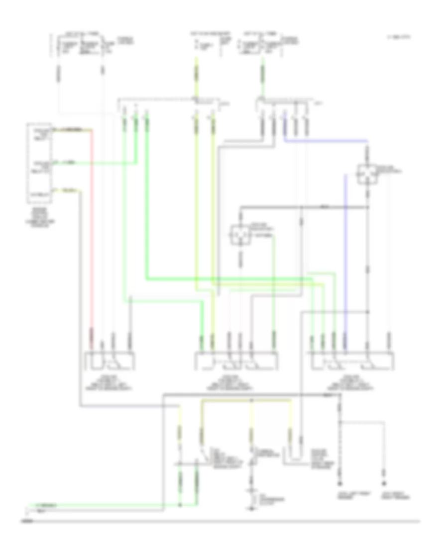
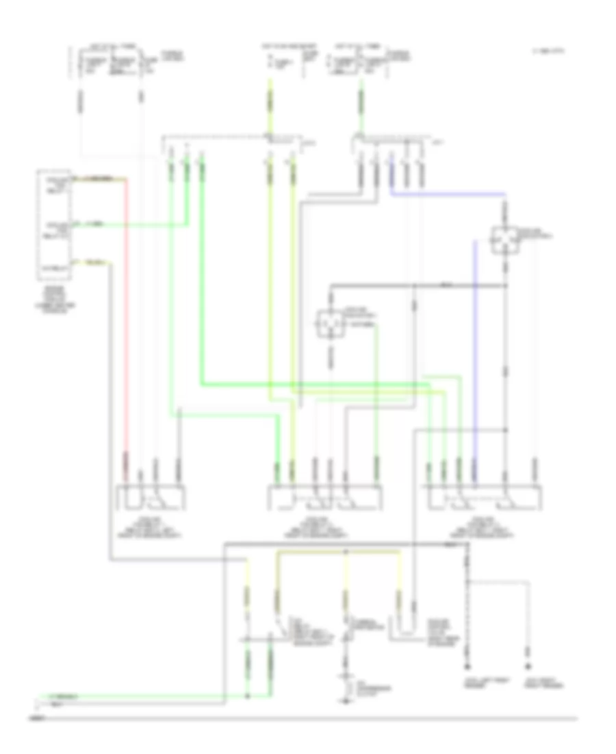
Air Conditioning Wiring Diagrams, Auto A/C (1 of 2) for Nissan Altima SE 1994
 https://portal-diagnostov.com/license.html
Automotive Electricians Portal FZCO
Automotive Electricians Portal FZCO
https://portal-diagnostov.com/license.html
https://portal-diagnostov.com/license.html
Automotive Electricians Portal FZCO
Automotive Electricians Portal FZCO
List of elements for Air Conditioning Wiring Diagrams, Auto A/C (1 of 2) for Nissan Altima SE 1994:
- (center g206
- (center of i/p)
- (left side
- (right de-
- (right rear of engine)
- (right side g203
- (right side of i/p)
- 1994 vftc c
- Air mix door motor
- Ambient sen
- Ambient sensor (center front
- Auto amp
- B/l
- Blower hi relay (right side of i/p)
- Blower hi-relay
- Blower motor
- Def
- Engine control module (below center console)
- F/d
- Fan control amp
- Fascia)
- Foot
- Fresh air vent door motor
- Fresh vent door motor
- Froster grille)
- Fuse 20 10a
- Fuse 26 10a
- Fuse 6 10a
- Fuse 7,8 20a
- Fuse block
- Ground
- Hot at all times
- Hot in on
- I/p)
- Illumination
- In vehicle sensor
- In-vehicle sensor
- Intake door motor
- Intake door motor control
- Intake door motor position
- Intake dr motor pos
- Interior lights system
- Kick panel)
- Mode door motor (center of i/p)
- Mode door motor control
- Mode door motor position
- Of i/p)
- Or start
- Pbr
- Pnk
- Position switch
- Power
- Red
- Sensor rtn
- Sun-load sensor
- Sunload sensor
- Thermal transmitter
- Thermo control amp
- Triple pressure switch
- Triple pressure switch (left front of engine compt)
- Vent
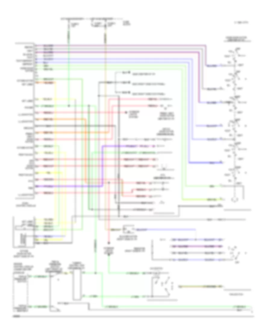
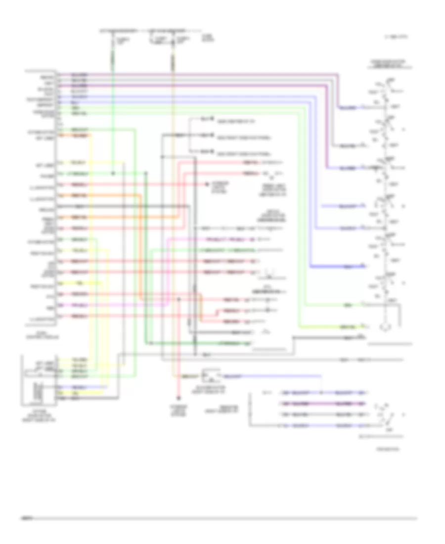
Air Conditioning Wiring Diagrams, Auto A/C (2 of 2) for Nissan Altima SE 1994
List of elements for Air Conditioning Wiring Diagrams, Auto A/C (2 of 2) for Nissan Altima SE 1994:
- (left front g100
- (right g101
- 1994 vftc c
- A/c compressor clutch
- A/c relay
- A/c relay (relay box 1, right front of engine compt)
- Cooling fan motor 1
- Cooling fan motor 2
- Cooling fan relay 1
- Cooling fan relay 1 (relay box 2, left front of engine compt)
- Cooling fan relay 2 (relay box 1, right front of engine compt)
- Cooling fan relay 2,3
- Cooling fan relay 3 (relay box 1, right front of engine compt)
- Engine control module (under center console)
- Fender)
- Front fender)
- Fuse 10a
- Fuse 4 10a
- Fuse box
- Fusible link f 30a
- Fusible link h 30a
- Fusible link box
- Fusible link e 75a
- Hot at all times
- Hot in on and start
- Idle air control valve (right rear of engine)
- J/c 1
- J/c 2
- Nca
- Thermal protector
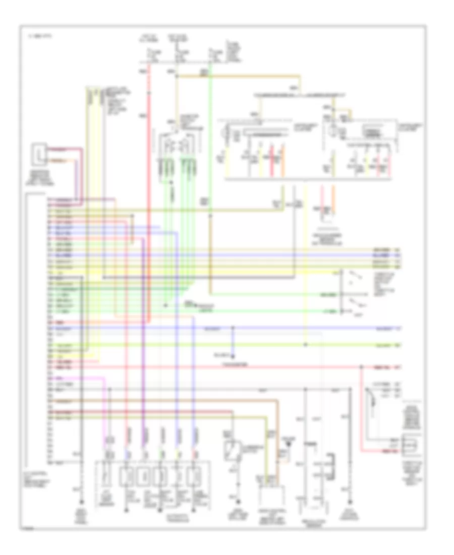
Air Conditioning Wiring Diagrams, Manual A/C (1 of 2) for Nissan Altima SE 1994
List of elements for Air Conditioning Wiring Diagrams, Manual A/C (1 of 2) for Nissan Altima SE 1994:
- (center of i/p)
- (center of i/p) g206
- (right side kick panel) g203
- (right side of i/p)
- 1994 vftc c
- A/c switch
- Air mix
- Air mix door motor
- B/l
- Bi-level
- Blower motor
- Console)
- Def
- Defrost
- Door motor
- Engine control module (under center
- F/d
- Fan switch
- Foot
- Foot/defrost
- Fresh vent
- Fresh vent door motor
- Fuse 6 10a
- Fuse 7 20a
- Fuse 8 20a
- Fuse block
- Ground
- Hot in on or start
- Illumination
- Intake door motor
- Intake motor
- Interior lights system
- Mode door motor
- Mode door motor (center of i/p)
- Not used
- Off
- Pbr
- Position sw
- Power
- Ptc
- Push control module
- Recirc
- Resistor
- Switch position
- Thermo control amp
- Triple pressure switch
- Triple pressure switch (left front of engine compt)
- Vent
Air Conditioning Wiring Diagrams, Manual A/C (2 of 2) for Nissan Altima SE 1994
List of elements for Air Conditioning Wiring Diagrams, Manual A/C (2 of 2) for Nissan Altima SE 1994:
- (left front g100
- (right g101
- 1994 vftc c
- A/c compressor clutch
- A/c relay
- A/c relay (relay box 1, right front of engine compt)
- Cooling fan motor 1
- Cooling fan motor 2
- Cooling fan relay 1
- Cooling fan relay 1 (relay box 2, left front of engine compt)
- Cooling fan relay 2 (relay box 1, right front of engine compt)
- Cooling fan relay 2,3
- Cooling fan relay 3 (relay box 1, right front of engine compt)
- Engine control module (under center console)
- Fender)
- Front fender)
- Fuse 10a
- Fuse 4 10a
- Fuse box
- Fusible link f 30a
- Fusible link h 30a
- Fusible link box
- Fusible link e 75a
- Hot at all times
- Hot in on and start
- Idle air control valve (right rear of engine)
- J/c 1
- J/c 2
- Nca
- Thermal protector
Heater Wiring Diagram for Nissan Altima SE 1994
List of elements for Heater Wiring Diagram for Nissan Altima SE 1994:
- (center of i/p)
- (center of i/p) g206
- (right side kick panel) g203
- (right side of i/p)
- 1994 vftc c
- Air mix
- Air mix door motor
- B/l
- Bi-level
- Blower motor
- Def
- Defrost
- Door motor
- F/d
- Fan switch
- Foot
- Foot/defrost
- Fresh vent
- Fresh vent door motor
- Fuse 6 10a
- Fuse 7 20a
- Fuse 8 20a
- Fuse block
- Ground
- Hot in on or start
- Illumination
- Intake door motor
- Intake motor
- Interior lights system
- Mode door motor
- Mode door motor (center of i/p)
- Not used
- Off
- Pbr
- Position sw
- Power
- Ptc
- Push control module
- Recirc
- Resistor
- Switch position
- Vent
ANTI-LOCK BRAKES
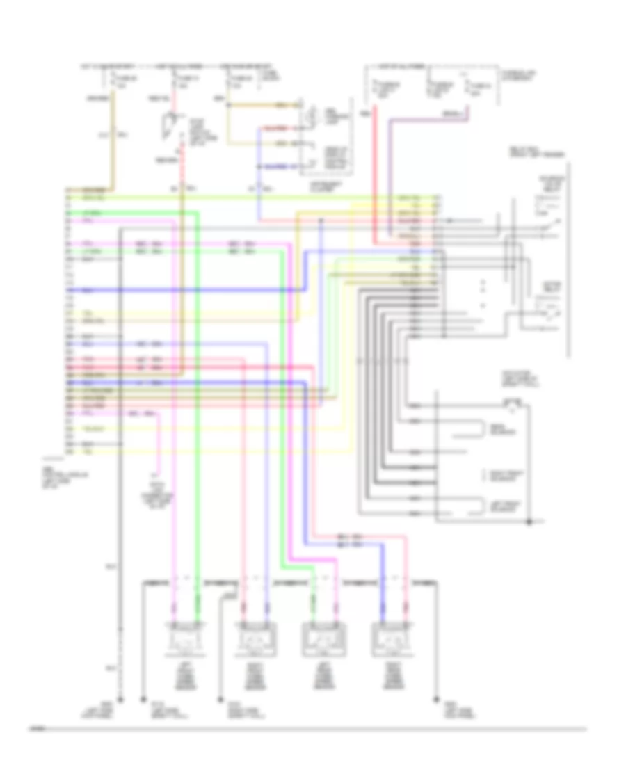
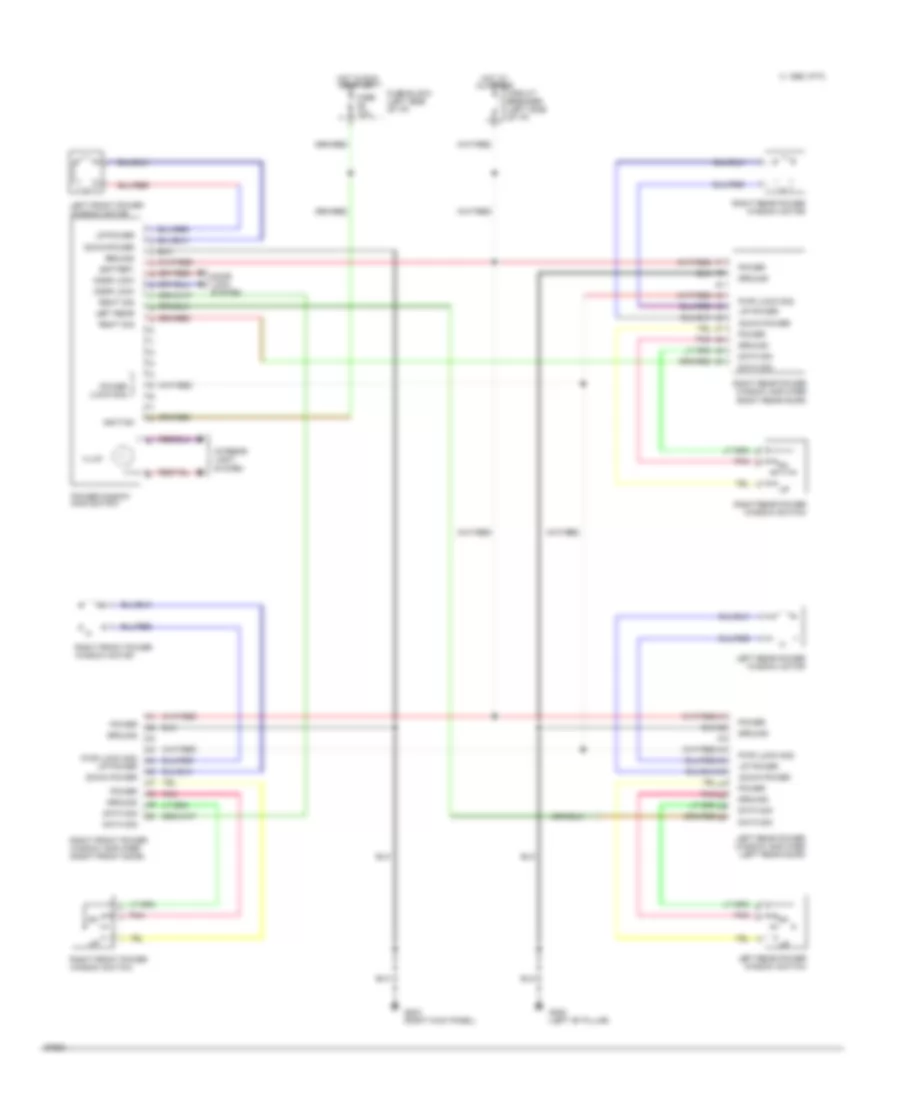
Anti-lock Brake Wiring Diagrams for Nissan Altima SE 1994
List of elements for Anti-lock Brake Wiring Diagrams for Nissan Altima SE 1994:
- 10a
- 15a
- 20a
- Abs control module (left side of i/p)
- Abs warning lamp
- Actuator (left side of safety wall)
- C12
- Data link connector (left side of i/p)
- Fuse 18
- Fuse 25
- Fuse 26
- Fuse 34
- Fuse block
- Fusible link & fuse box
- Fusible link a 20a
- Fusible link e 75a
- G116 (left side safety wall)
- G123 (right side safety wall)
- G200 (left side kick panel)
- Head up display control module
- Hot at all times
- Hot in on or start
- Instrument cluster
- Left front solenoid
- Left front wheel speed sensor
- Left rear wheel speed sensor
- Motor
- Motor relay
- Nca
- Pnk
- Rear solenoid
- Red
- Relay box (front left fender)
- Right front solenoid
- Right front wheel speed sensor
- Right rear wheel speed sensor
- Smj
- Solenoid valve relay
- Stop lamp switch (left side of i/p)
ANTI-THEFT
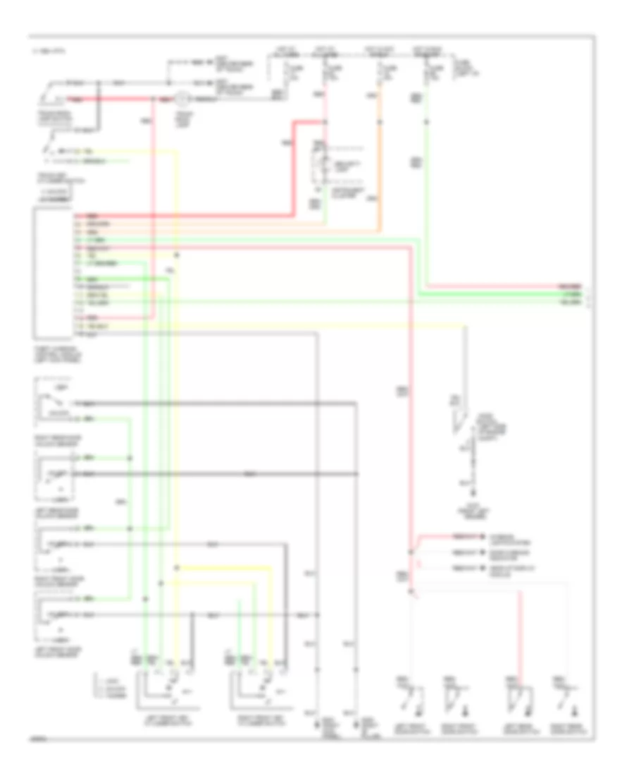
Anti-theft Wiring Diagram (1 of 2) for Nissan Altima SE 1994
List of elements for Anti-theft Wiring Diagram (1 of 2) for Nissan Altima SE 1994:
- (center rear
- (left kick panel)
- (left side of engine compt)
- 1994 vftc c
- Control module
- Door warning indicator
- Fuse 10a
- Fuse block (left i/p)
- G100 (front left fender)
- G203 (right kick panel)
- G305 (right "b" pillar)
- G407
- Head-up display module
- Hood
- Hot at all times
- Hot in acc or run
- Hot in run or start
- Instrument cluster
- Interior lights system
- Left front door switch
- Left front door unlock sensor
- Left front key cylinder switch
- Left rear door switch
- Left rear door unlock sensor
- Lock
- Of trunk)
- Red
- Right front door switch
- Right front door unlock sensor
- Right front key cylinder switch
- Right rear door switch
- Right rear door unlock sensor
- Security lamp
- Switch
- Tamper
- Theft warning
- Trunk key cylinder switch
- Trunk room lamp
- Trunk room lamp switch
- Unlock
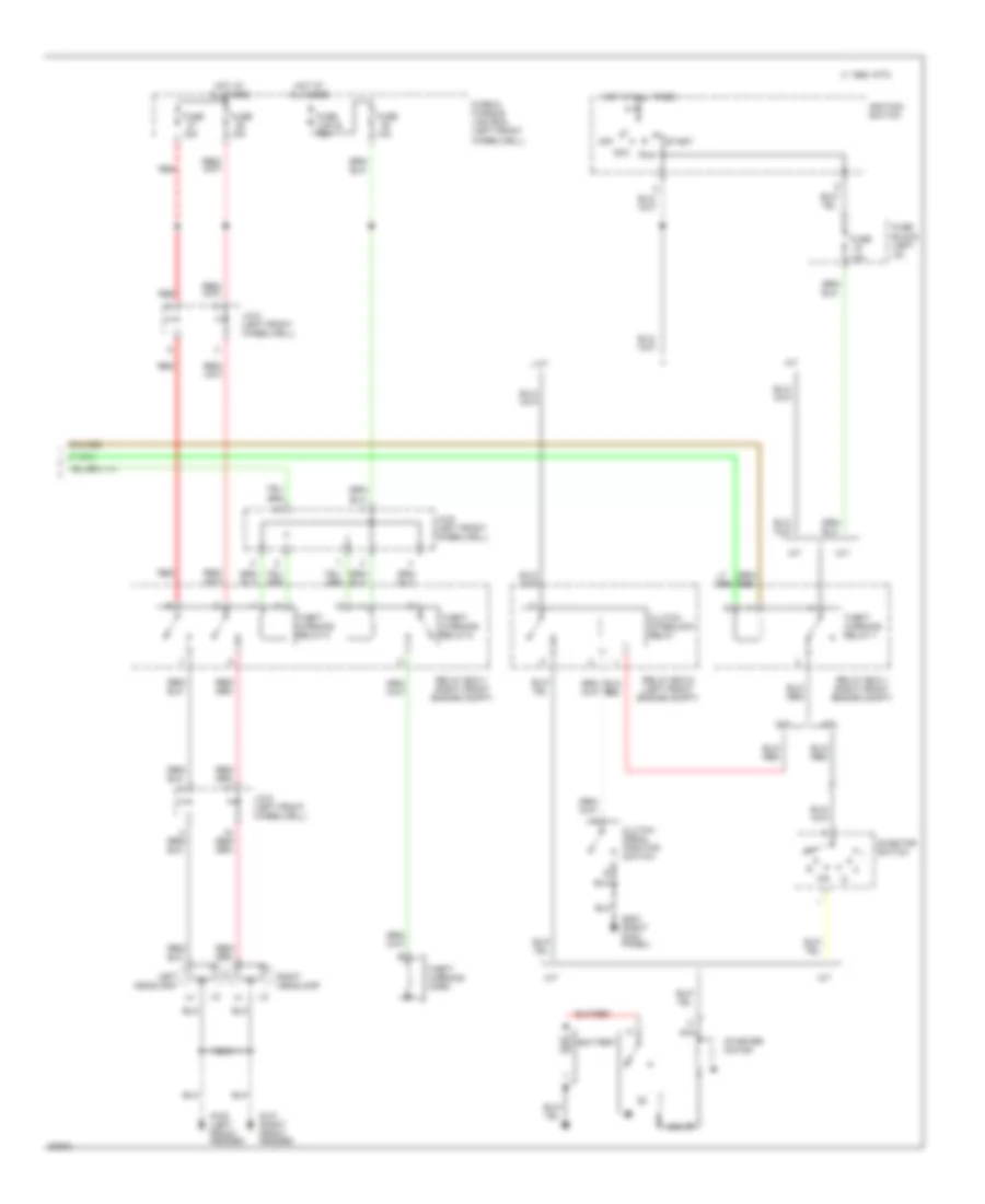
Anti-theft Wiring Diagram (2 of 2) for Nissan Altima SE 1994
List of elements for Anti-theft Wiring Diagram (2 of 2) for Nissan Altima SE 1994:
- 10a
- 15a
- 1995 vftc c
- A/t
- Acc
- B nca
- Battery
- Clutch interlock relay
- Clutch pedal position switch
- Fuse
- Fuse & fusible link box (left front
- Fuse 10a
- Fuse block (left
- Fuse link e 75a
- G100 (left front fender)
- G101 (right front fender)
- G203 (right kick panel)
- Headlamp
- Horn
- Hot at all times
- I/p)
- Ignition switch
- Inhibitor switch
- J/c-3 (left front wheelwell)
- J/c-5 (left front wheelwell)
- J/c-6 (left front wheelwell)
- Left
- M/t
- Nca
- Off
- Red
- Relay box-1 (right front engine compt)
- Relay box-2 (left front engine compt)
- Right headlamp
- Run
- Start
- Starter motor
- Theft
- Theft warning relay-1
- Theft warning relay-2
- Theft warning relay-3
- Warning
- Wheelwell)
BODY COMPUTER
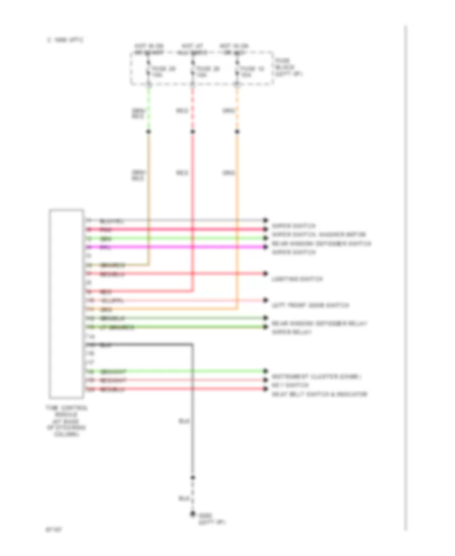
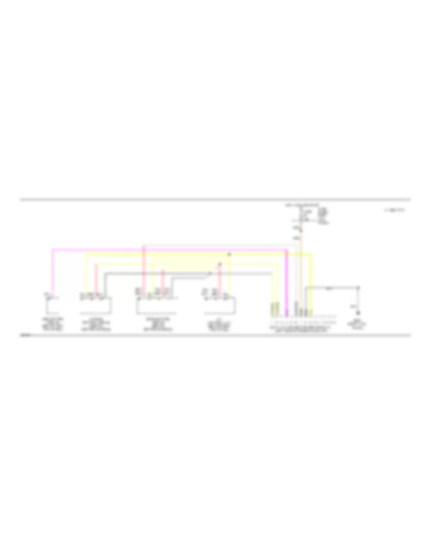
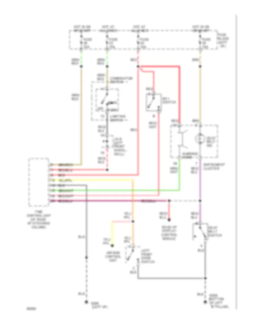
Time Control Module Wiring Diagram for Nissan Altima SE 1994
List of elements for Time Control Module Wiring Diagram for Nissan Altima SE 1994:
- C 1995 vftc
- Fuse 12 10a
- Fuse 20 10a
- Fuse 26 10a
- Fuse block (left i/p)
- G202 (left i/p)
- Hot at all times
- Hot in on or acc
- Hot in on or start
- Instrument cluster (chime)
- Key switch
- Left front door switch
- Lighting switch
- Pnk
- Rear window defogger relay
- Rear window defogger switch
- Red
- Seat belt switch & indicator
- Time control module (at base of steering column)
- Wiper relay
- Wiper switch
- Wiper switch, washer motor
COMPUTER DATA LINES
Data Link Connector Wiring Diagram for Nissan Altima SE 1994
List of elements for Data Link Connector Wiring Diagram for Nissan Altima SE 1994:
- (left side of steering column)
- (right kick
- 1995 vftc c
- A/t control unit (behind right kick panel)
- Abs control module (behind left kick panel)
- Air bag control module (behind center console)
- Data link connector (for consult)
- Eccs control module (behind center console)
- Fuse 10a
- Fuse block (left kick panel)
- G203
- Hot in run or start
- Panel)
- Red
COOLING FAN
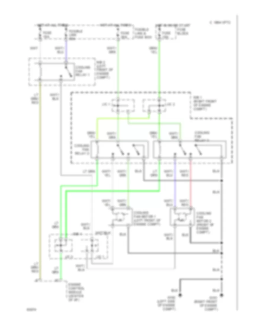
Cooling Fan Wiring Diagram for Nissan Altima SE 1994
List of elements for Cooling Fan Wiring Diagram for Nissan Altima SE 1994:
- 1994 vftc c
- Cooling fan motor 1 (left front of engine compt)
- Cooling fan motor 2 (front of engine compt)
- Cooling fan relay 1
- Cooling fan relay 2
- Cooling fan relay 3
- Engine control module (center of i/p)
- Fuse 10a
- Fuse 30a
- Fuse block
- Fusible link & fuse box
- Fusible link 30a
- G101 (right front of engine compt)
- G102 (left side of engine compt)
- Hot at all times
- Hot in on or start
- J/c 1
- J/c 2
- R/b 1
- R/b 1 (right front of engine compt)
- R/b 2 (left front of engine compt)
CRUISE CONTROL
Cruise Control Wiring Diagram for Nissan Altima SE 1994
List of elements for Cruise Control Wiring Diagram for Nissan Altima SE 1994:
- 1995 vftc c
- A/t
- A/t control unit (right kick panel)
- A/t only
- Act. cntrl
- Actuator control
- Air valve solenoid
- Ascd actuator (left side of safety wall)
- Ascd cancel switch (top of brake
- Ascd clutch switch (m/t only) (top of clutch
- Ascd control unit (left side of i/p)
- Ascd hold relay (relay box 2, (left front fender)
- Ascd steering switch
- Ascd sw.
- Ascd switch
- Cancel
- Crs. cancl
- Cruise ind.
- Cruise signal
- Digital control unit
- Fuse & fusible link box (left front fender)
- Fuse 18 15a
- Fuse 25 10a
- Fuse 26 10a
- Fuse 35 10a
- Fuse block (left side of i/p)
- G100 (left front fender)
- G202 (left side of i/p)
- Ground
- Horn relay (relay box 1, right front fender)
- Horns system (horn switch)
- Horns system (horn)
- Hot at all times
- Hot in on or start
- Inhibitor relay (a/t only) (relay box 2, (left front fender)
- Inhibitor switch (a/t only) (left side of transmission)
- Instrument cluster
- Interior lights system
- J/c 5 (left front fender)
- M/t
- Nca
- Od cut
- Od cut signal
- Off
- Pedal support)
- Pnk
- Red
- Release valve solenoid
- Resume/ accelerate
- Set/coast
- Speed
- Speed- ometer
- Spiral cable
- St lmp sw.
- Steering switch
- Stop lamp switch (top of brake pedal support)
- Vacuum motor
- Vehicle speed sensor (top of trans.)
- W/ hud
- W/o hud
DEFOGGERS
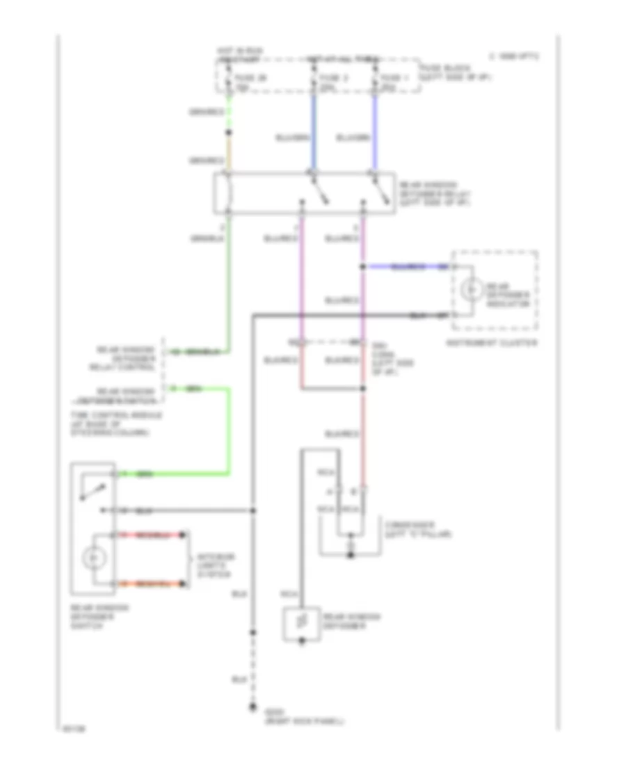
Defogger Wiring Diagram for Nissan Altima SE 1994
List of elements for Defogger Wiring Diagram for Nissan Altima SE 1994:
- 1995 vftc c
- Condenser (left "c" pillar)
- Fuse 1 20a
- Fuse 2 20a
- Fuse 26 10a
- Fuse block (left side of i/p)
- G203 (right kick panel)
- Hot at all times
- Hot in run or start
- Instrument cluster
- Interior lights system
- Nca
- Rear defogger indicator
- Rear window defogger
- Rear window defogger relay (left side of i/p)
- Rear window defogger relay control
- Rear window defogger switch
- Smj conn. (left side of i/p)
- Time control module (at base of steering column)
ENGINE PERFORMANCE
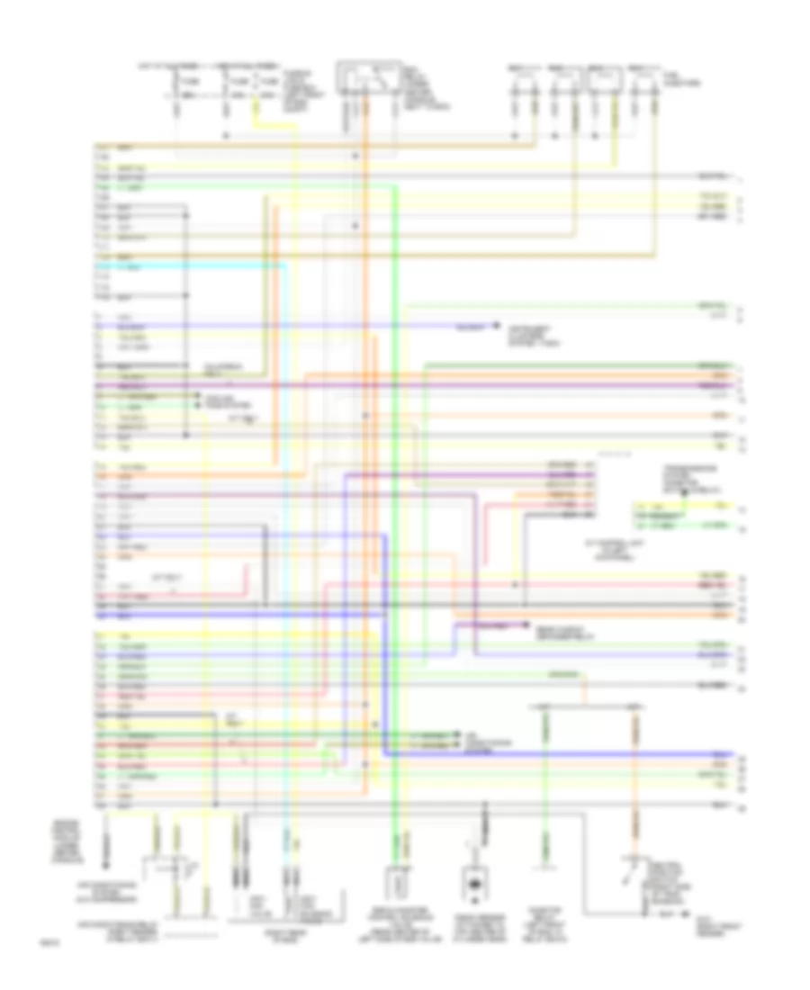
Engine Performance Wiring Diagrams (1 of 2) for Nissan Altima SE 1994
List of elements for Engine Performance Wiring Diagrams (1 of 2) for Nissan Altima SE 1994:
- (right rear of eng)
- (tach)
- 10a
- 25a
- A/t
- A/t control unit (in left kick panel)
- A/t only
- Air conditioning relay (right fender, in relay box-1)
- Air conditioning system
- Air conditioning system (a/c compressor)
- California only
- Cooling fans system
- Ecm relay (under center console, next to ecm)
- Egr & canister control solenoid valve (rear center of left side of egr valve)
- Engine control module (under center console)
- Fuel injectors
- Fuse
- Fusible link & fuse box (left front of eng compt)
- G101 (right front fender)
- Hot at all times
- Iacv- aac valve
- Iacv- ficd solenoid valve
- Inhibitor relay (left front of eng, in relay box-2)
- Instrument clusters system
- J/c
- Knock sensor (attached to top center of cylinder head)
- M/t
- Nca
- Neutral position switch (right side of tran- smission)
- No.1
- No.2
- No.3
- No.4
- Rear window defogger relay
- Transmissions system (inhibitor switch & relay)
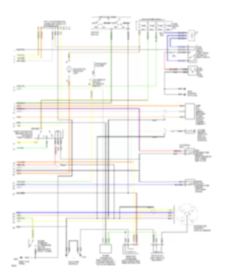
Engine Performance Wiring Diagrams (2 of 2) for Nissan Altima SE 1994
List of elements for Engine Performance Wiring Diagrams (2 of 2) for Nissan Altima SE 1994:
- (on intake manifold)
- (right kick panel)
- (right side of air cleaner assembly, top of maf sensor)
- (w/o head-up
- 10a
- 15a
- Acc
- California only
- Data link connector (under left side of i/p, on fuse block)
- Dislpay) (w/ head-up
- Display)
- Distributor/ camshaft position sensor
- Egr temperature sensor (rear center of eng, under egr valve)
- Engine coolant temperature sensor (left rear of eng)
- Fuel pump (in fuel tank)
- Fuel pump relay (left front of eng, in relay box-2)
- Fuse
- Fuse block (i/p)
- G131
- G203
- G305 (on right "b" pillar)
- Hot at all times
- Hot in start or on
- Ignition coil (left front of eng compt)
- Ignition switch
- Instrument cluster
- J/c
- Malfunction indicator lamp
- Mass air flow sensor (between intake manifold and air cleaner assembly)
- Nca
- Off
- Oxygen sensor (front of eng, on exhaust manifold)
- Power steering/ oil pressure switch (behind right strut tower)
- Power transistor
- Resistor/ condenser (right side of eng, near distributor)
- Smj
- Start
- Throttle position sensor & switch (on side of throttle body)
- Vss
EXTERIOR LIGHTS
Backup & Turn Lamps Wiring Diagram for Nissan Altima SE 1994
List of elements for Backup & Turn Lamps Wiring Diagram for Nissan Altima SE 1994:
- (center rear of trunk)
- A/t
- Flasher module (left side of i/p)
- Fuse 22 10a
- Fuse 24 10a
- Fuse 25 10a
- Fuse block (left side of i/p)
- G100 (left front fender)
- G101 (right front fender)
- G203 (right kick panel)
- G407
- Hazard
- Hazard switch
- Head-up display unit
- Hot at all times
- Hot in run or start
- Ill.
- Inhibitor switch (on trans)
- Instrument cluster
- Interior lights system
- Left front turn light
- Left rear tail/ stop/ turn/ back-up lights
- Left turn ind.
- M/t
- Position switch (on trans)
- Right front turn light
- Right rear tail/ stop/ turn/ back-up lights
- Right turn ind.
- Turn signal switch
- W/ head-up display only
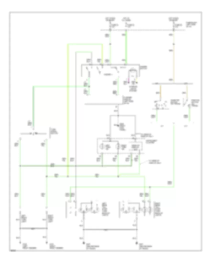
Cornering Lamps Wiring Diagram for Nissan Altima SE 1994
List of elements for Cornering Lamps Wiring Diagram for Nissan Altima SE 1994:
- Canada only
- Cornering lamp relay (relay box 2, left front of engine compt)
- Cornering lamp switch
- Daytime light control unit (right kick panel)
- Diode (left side of i/p)
- Flash to pass
- Fuse & fusible link box (left front fender)
- Fuse 24 10a
- Fuse 37 15a
- Fuse block (left side of i/p)
- G100 (left front fender)
- G101 (right front fender)
- Head
- Headlights system (left headlight)
- Hi beam
- Hot at all times
- Hot in run or start
- J/c 3 (left front fender)
- J/c 4 (left front fender)
- J/c 5 (left front fender)
- J/c 6 (left front fender)
- Left cornering light
- Light switch
- Off
- Park
- Red
- Right cornering light
Park, Stop & Tail Lamps Wiring Diagram for Nissan Altima SE 1994
List of elements for Park, Stop & Tail Lamps Wiring Diagram for Nissan Altima SE 1994:
- Fuse 18 15a
- Fuse 23 15a
- Fuse block (left side of i/p)
- G100 (left front fender)
- G101 (right front fender)
- G407 (center rear of trunk)
- Head
- High mounted stop light
- Hot at all times
- J/c 6 (left front fender)
- Left front clearance/ cornering light
- Left front side marker light
- Left license light
- Left rear side marker light
- Left rear tail/ stop/ turn lights
- Light switch
- Off
- Park
- Right front clearance/ cornering light
- Right front side marker light
- Right license light
- Right rear side marker light
- Right rear tail/ stop/ turn lights
- Stop lamp switch (top of brake pedal support)
- W/o rear air spoiler
- W/rear air spoiler
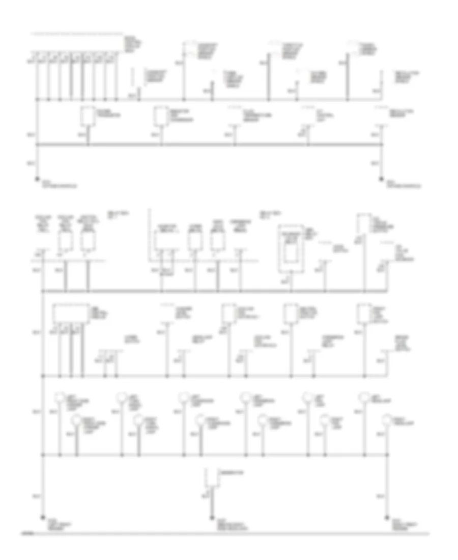
GROUND DISTRIBUTION
Ground Distribution Wiring Diagram (1 of 3) for Nissan Altima SE 1994
List of elements for Ground Distribution Wiring Diagram (1 of 3) for Nissan Altima SE 1994:
- A/c triple pressure switch
- A/t control unit
- Abs control module
- Abs relay box
- Ascd hold relay
- Brake fluid level switch
- Camshaft position sensor
- Camshaft position sensor shield
- Cooling fan motor no.1
- Cooling fan motor no.2
- Cooling fan relay no.1
- Cooling fan relay no.2
- Cornering lamp relay
- Eccs control module (ecm)
- Fluid temperature sensor
- Front fog lamp switch
- G100 (left front fender)
- G101 (right front fender)
- G107 (behind right side headlamp)
- G131 (intake manifold)
- Generator
- Headlamp relay
- Hood switch
- Iac valve ficd solenoid
- Ignition relay no.2 (sun- roof)
- Inhibitor relay
- Knock sensor shield
- Left clearance lamp
- Left cornering lamp
- Left fog lamp
- Left front side marker lamp
- Left headlamp
- Left turn signal lamp
- Mass air flow sensor shield
- Neutral position switch
- Oxygen sensor shield
- Power transistor
- Relay box no. 1
- Relay box no. 2
- Resistor and condensor
- Revolution sensor
- Revolution sensor shield
- Right clearance lamp
- Right cornering lamp
- Right fog lamp
- Right front side marker lamp
- Right headlamp
- Right turn signal lamp
- Solenoid valve relay
- Throttle position sensor shield
- Washer level switch
- Wiper relay
- Wiper switch
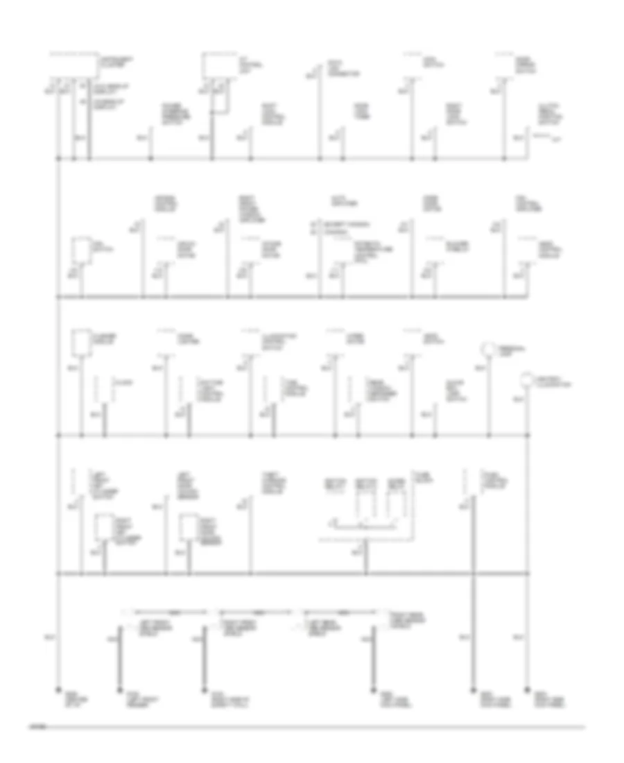
Ground Distribution Wiring Diagram (2 of 3) for Nissan Altima SE 1994
List of elements for Ground Distribution Wiring Diagram (2 of 3) for Nissan Altima SE 1994:
- (canada)
- (except canada)
- (w/head-up display)
- (w/o head-up display)
- A/t control unit
- Acces. relay
- Air bag control module
- Air mix door motor
- Ascd control module
- Ascd switch
- Ashtray illumination
- Auto amplifier
- Blower hi-relay
- Cigar lighter
- Clock
- Clutch pedal position switch
- Data link connector
- Daytime light control module
- Door lock timer
- Door mirror switch
- Fan control amplifier
- Fan switch
- Flasher module
- Fuse block
- G100 (left front fender)
- G123 (right side of safety wall)
- G200 (left side kick panel)
- G203 (right side kick panel)
- G206 (center of i/p)
- Glove box lamp switch
- Ignition relay-1
- Ignition relay-2
- Illumination control switch
- Instrument cluster
- Intake door motor
- Left front abs sensor shield
- Left front door unlock sensor
- Left front key cylinder switch
- Left rear abs sensor shield
- M/t
- Main switch
- Mode door motor
- Nca
- Personal lamp
- Potentio temperature control (ptc)
- Power steering pressure switch
- Push control module
- Rear window defogger switch
- Right door lock switch
- Right front abs sensor shield
- Right front door unlock sensor
- Right front key cylinder switch
- Right front power window amplifier
- Right rear abs sensor shield
- Shift lock control module
- Theft warning control module
- Time control module
- Wiper motor
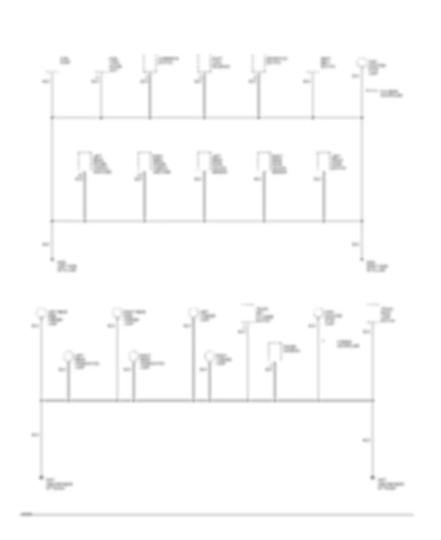
Ground Distribution Wiring Diagram (3 of 3) for Nissan Altima SE 1994
List of elements for Ground Distribution Wiring Diagram (3 of 3) for Nissan Altima SE 1994:
- Detention switch
- Fuel pump
- Fuel tank gauge unit
- G305 (right side "b" pillar)
- G308 (left side "b" pillar)
- G407 (center rear of trunk)
- High mounted stop lamp
- High- mounted stop lamp
- Left front door switch
- Left license lamp
- Left rear combination lamp
- Left rear door unlock sensor
- Left rear power window amplifier
- Left rear side marker lamp
- Overdrive switch
- Power antenna
- Right license lamp
- Right rear combination lamp
- Right rear door unlock sensor
- Right rear power window amplifier
- Right rear side marker lamp
- Seat belt switch
- Shift lock solenoid
- Trunk key cylinder switch
- Trunk room lamp switch
- W/o rear air spoiler
- W/rear air spoiler
HEADLIGHTS
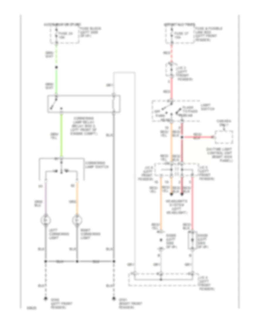
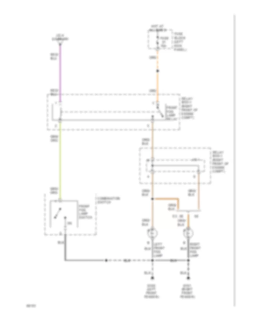
Fog Lamps Wiring Diagram for Nissan Altima SE 1994
List of elements for Fog Lamps Wiring Diagram for Nissan Altima SE 1994:
- (left front fender)
- (right front fender)
- 15a
- Combination switch
- Ex. se
- Front fog lamp relay
- Front fog lamp switch
- Fuse
- Fuse block (left kick panel)
- G100
- G101
- Hot at all times
- J/c-1
- J/c-4 (lo beam)
- Left front fog lamp
- Relay box-1 (right front of engine compt)
- Right front fog lamp
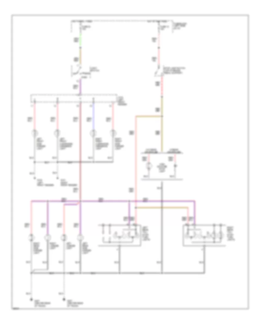
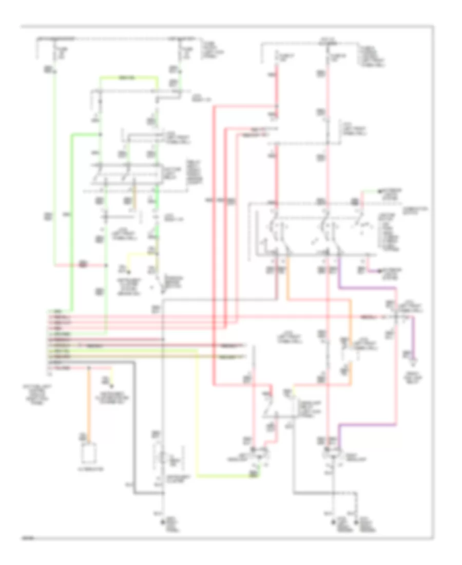
Headlamps Wiring Diagram, with DRL for Nissan Altima SE 1994
List of elements for Headlamps Wiring Diagram, with DRL for Nissan Altima SE 1994:
- (brake ind.)
- (left front
- 10a
- Alternator
- Combination switch
- Daytime light control module (right kick panel)
- Daytime light relay
- Exterior lights system
- Front fog lamp relay
- Fuse
- Fuse & fusible link box (left front
- Fuse 36 15a
- Fuse 37 15a
- Fuse block (left kick panel)
- G100 (left front fender)
- G101 (right front fender)
- G203 right kick panel)
- Headlamp
- Headlamp relay (left kick panel)
- Hi a
- Hi beam ind.
- Hot at all times
- Hot in on or start
- Hot in start
- Instrument cluster
- Instrument cluster system
- Instrument cluster system (charge ind.)
- J/c-3 (left front
- J/c-4
- J/c-5
- J/c-6
- J/c-6 (left front
- J/c-8 (right i/p)
- Left
- Lighting switch
- Off
- Park head lo beam hi beam flash- to-pass
- Parking brake switch
- Red
- Relay box-1 (right front engine compt)
- Right headlamp
- Wheelwell)
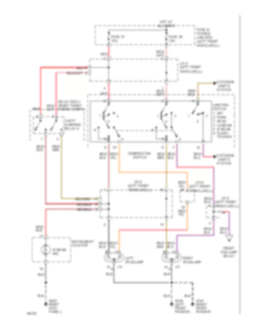
Headlamps Wiring Diagram, without DRL for Nissan Altima SE 1994
List of elements for Headlamps Wiring Diagram, without DRL for Nissan Altima SE 1994:
- (left front
- Combination
- Exterior lights system
- Front fog lamp relay
- Fuse & fusible link box (left front
- Fuse 36 15a
- Fuse 37 15a
- G100 (left front fender)
- G101 (right front fender)
- G203 right kick panel)
- Hi a
- Hi beam ind.
- Hot at all times
- Instrument cluster
- J/c-3 (left front
- J/c-4
- J/c-5
- J/c-6
- Left headlamp
- Lighting switch
- Off
- Park head lo beam hi beam flash- to-pass
- Red
- Relay box-1 (right front engine compt)
- Right headlamp
- Switch
- Theft warning relay-3
- Wheelwell)
HORN
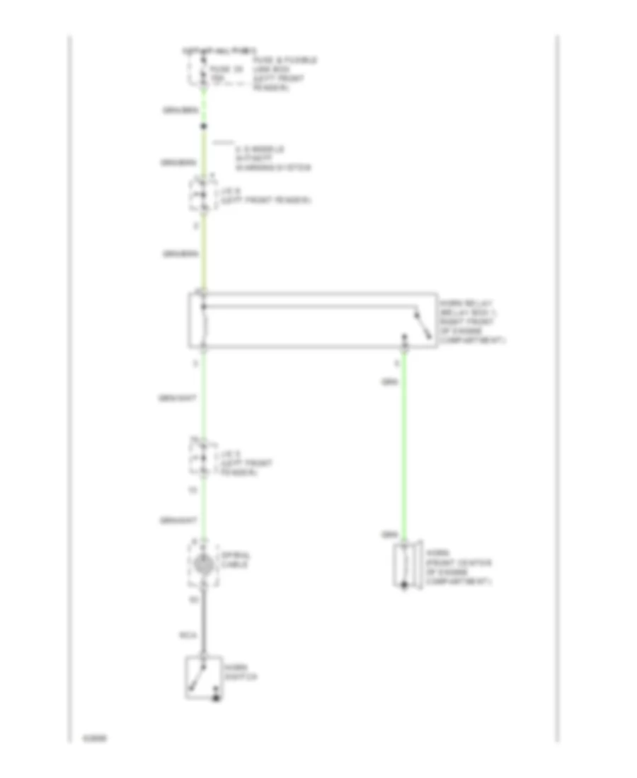
Horn Wiring Diagram for Nissan Altima SE 1994
List of elements for Horn Wiring Diagram for Nissan Altima SE 1994:
- Fuse & fusible link box (left front fender)
- Fuse 35 10a
- Horn (front center of engine compartment)
- Horn relay (relay box 1, right front of engine compartment)
- Horn switch
- Hot at all times
- J/c 5 (left front fender)
- J/c 6 (left front fender)
- Nca
- Spiral cable
- U.s models w/theft warning system
INSTRUMENT CLUSTER
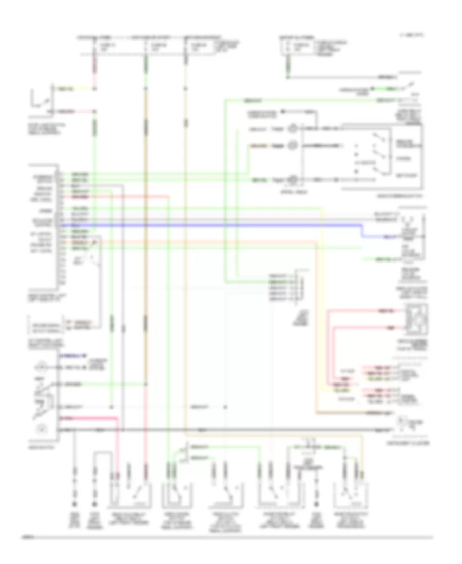
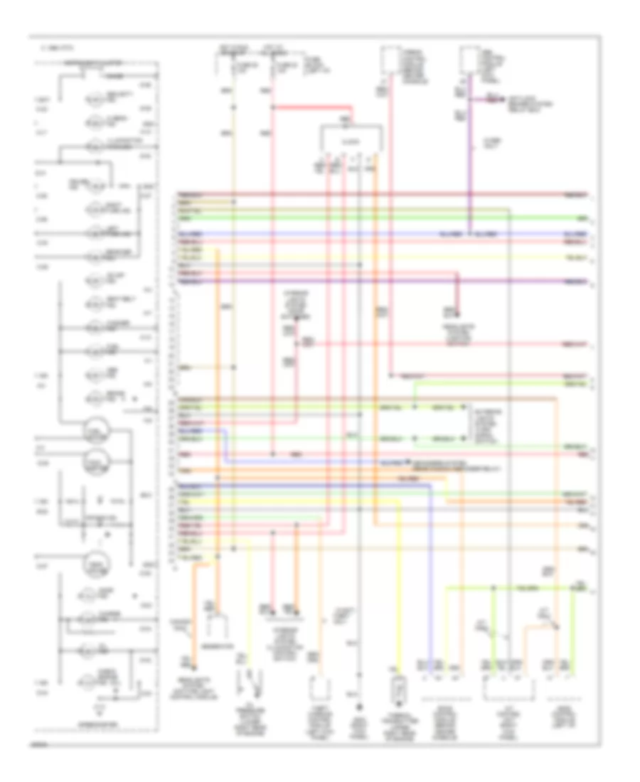
Instrument Cluster Wiring Diagram, with Head-Up Display (1 of 2) for Nissan Altima SE 1994
List of elements for Instrument Cluster Wiring Diagram, with Head-Up Display (1 of 2) for Nissan Altima SE 1994:
- (mil)
- 1995 vftc c
- A-1
- A-10
- A-11
- A-12
- A-2
- A-3
- A-4
- A-6
- A-7
- A-8
- A-9
- A/t control unit (right kick panel)
- A/t only
- Abs control module (left kick panel)
- Abs ind.
- Air bag ind.
- Airbag control module (behind center console)
- Anti-lock brakes system (relay box)
- Ascd control module (left i/p)
- B-22
- B-23
- Bat
- Brake ind.
- C-25
- C-26
- C-27
- C-28
- C-29
- C-30
- C-32
- C-34
- Canada only
- Charge ind.
- Check engine ind.
- Chime
- Clock
- Cruise ind.
- D-35
- D-36
- D-37
- D-38
- D-39
- D-40
- D-41
- D-42
- D-43
- D-44
- Defoggers system (rear window defogger relay)
- Door ind.
- Eccs control module (behind center console)
- Exterior lights system (turn signal switch)
- Fuel gauge
- Fuel ind.
- Fuse 20 10a
- Fuse 25 10a
- Fuse block (left i/p)
- G203 (right kick panel)
- Generator
- Gnd
- Headlights system (daytime light control module)
- Headlights system (lighting switch)
- Hi beam ind.
- Hot at all times
- Hot in run or start
- Ign
- Illumination (4 bulbs)
- Instrument cluster
- Interior lights system (door switches)
- Interior lights system (illumination control switch)
- Left turn ind.
- Od off ind.
- Oil ind.
- Oil pressure switch (lower right rear of engine)
- Rear def. ind.
- Red
- Right turn ind.
- Seat belt ind.
- Security ind.
- Speedometer
- Tach- ometer
- Temp. gauge
- Theft only
- Theft warning control module (left kick panel)
- Thermal transmitter (upper right rear of engine)
- W/abs only
- W/anti-
- Washer ind.
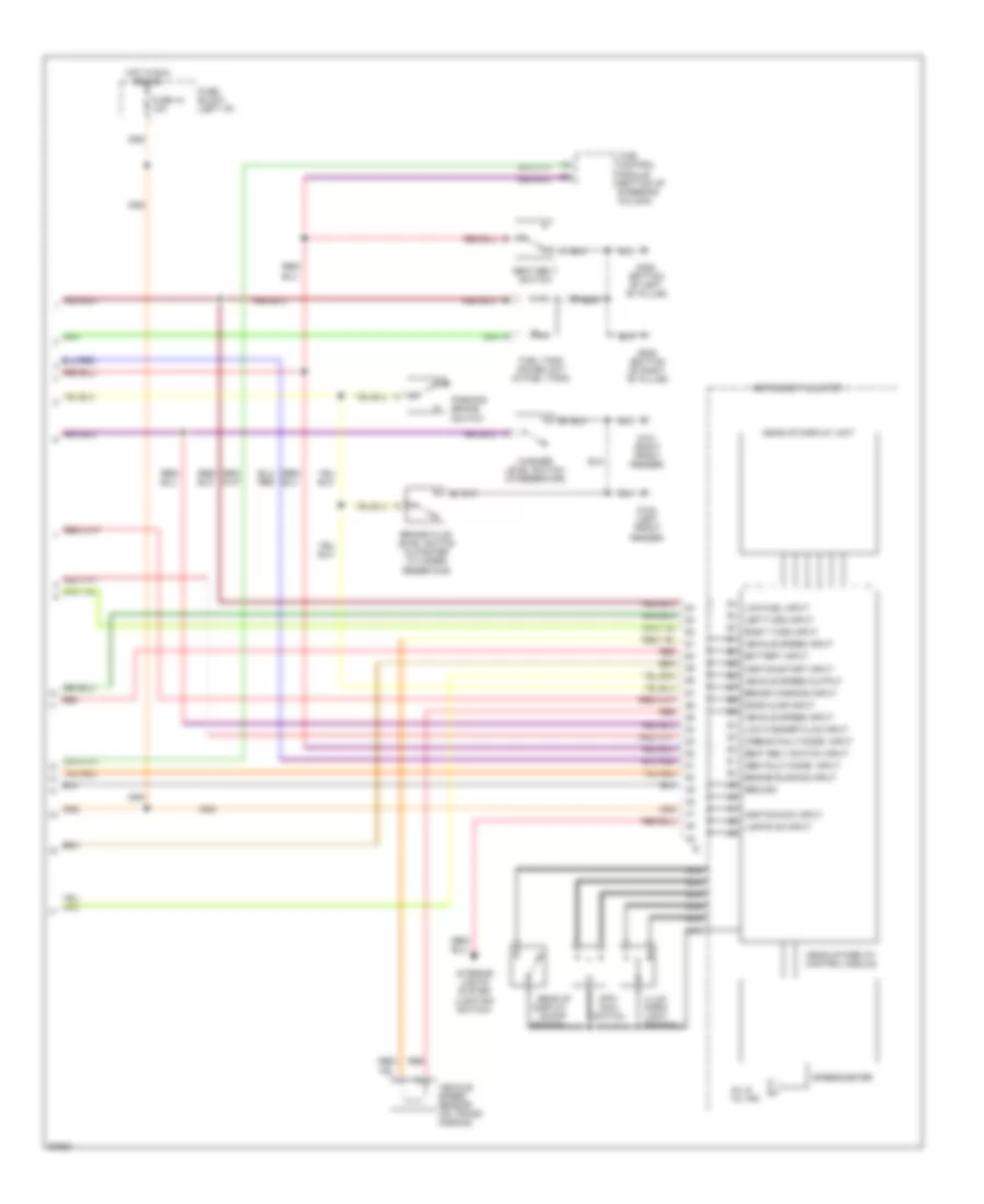
Instrument Cluster Wiring Diagram, with Head-Up Display (2 of 2) for Nissan Altima SE 1994
List of elements for Instrument Cluster Wiring Diagram, with Head-Up Display (2 of 2) for Nissan Altima SE 1994:
- Abs fault/code input
- Airbag fault/code input
- Battery input
- Brake fluid level switch (in master cylinder reservoir)
- Brake warning input
- Display on-off switch
- Door ajar input
- Engine running input
- Fuel tank gauge unit (in fuel tank)
- Fuse 12 10a
- Fuse block (left i/p)
- G100 (left front fender)
- G101 (right front fender)
- G305 (bottom of right "b" pillar)
- G308 (bottom of left "b" pillar)
- Ground
- Head-up
- Head-up display control module
- Head-up display unit
- Hot in run or acc
- Ignition/acc input
- Ignition/start input
- Illum. dark/ light switch
- Instrument cluster
- Interior lights system (lighting switch)
- Left turn input
- Lights on input
- Low fuel input
- Low washer fluid input
- Mil & oil ind.
- Mph/ km/h
- Nca
- Parking brake switch
- Red
- Right turn input
- Seat belt switch
- Seat belt switch input
- Speedometer
- Switch
- Time control module (bottom of steering column)
- Vehicle speed input
- Vehicle speed output
- Vehicle speed sensor (on trans- mission)
- Washer level switch (in reservoir)
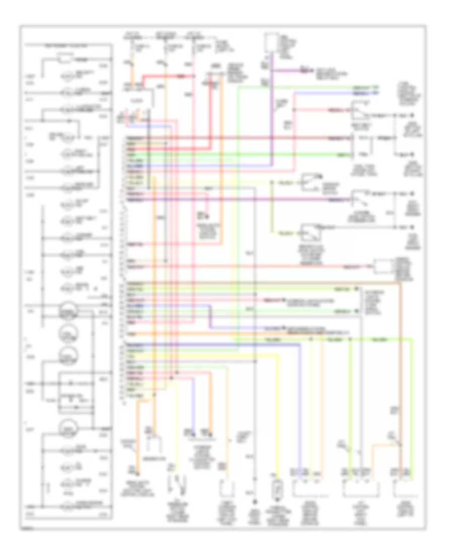
Instrument Cluster Wiring Diagram, without Head-Up Display for Nissan Altima SE 1994
List of elements for Instrument Cluster Wiring Diagram, without Head-Up Display for Nissan Altima SE 1994:
- (mil)
- A-1
- A-10
- A-11
- A-12
- A-2
- A-3
- A-4
- A-5
- A-6
- A-7
- A-8
- A-9
- A/t control unit (right kick panel)
- A/t only
- Abs control module (left kick panel)
- Abs ind.
- Air bag ind.
- Airbag control module (behind center console)
- Anti-lock brakes system (relay box)
- Ascd control module (left i/p)
- B-19
- B-22
- B-23
- Bat
- Brake fluid level switch (in master cylinder reservoir)
- Brake ind.
- C-25
- C-26
- C-27
- C-28
- C-29
- C-30
- C-31
- C-32
- C-34
- Canada only
- Charge ind.
- Check engine ind.
- Chime
- Clock
- Cruise ind.
- D-35
- D-36
- D-37
- D-38
- D-39
- D-40
- D-41
- D-42
- D-43
- D-44
- Defoggers system (rear window defogger relay)
- Door ind.
- Eccs control module (behind center console)
- Exterior lights system (turn signal switch)
- Fuel gauge
- Fuel ind.
- Fuel tank gauge unit (in fuel tank)
- Fuse 12 10a
- Fuse 20 10a
- Fuse 25 10a
- Fuse block (left i/p)
- G100 (left front fender)
- G101 (right front fender)
- G203 (right kick panel)
- G305 (bottom of right "b" pillar)
- G308 (bottom of left "b" pillar)
- Generator
- Gnd
- Headlights system (daytime light control module)
- Headlights system (lighting switch)
- Hi beam ind.
- Hot at all times
- Hot in run or start
- Ign
- Illumination (4 bulbs)
- Instrument cluster
- Interior lights system (door switches)
- Interior lights system (illumination control switch)
- Left turn ind.
- Od off ind.
- Oil ind.
- Oil pressure switch (lower right rear of engine)
- Parking brake switch
- Rear def. ind.
- Red
- Right turn ind.
- Seat belt ind.
- Seat belt switch
- Security ind.
- Speed- ometer
- Tach- ometer
- Temp. gauge
- Theft only
- Theft warning control module (left kick panel)
- Thermal transmitter (upper right rear of engine)
- Time control module (bottom of steering column)
- Vehicle speed sensor (on trans- mission)
- W/abs only
- W/anti-
- Washer ind.
- Washer level switch (in reservoir)
INTERIOR LIGHTS
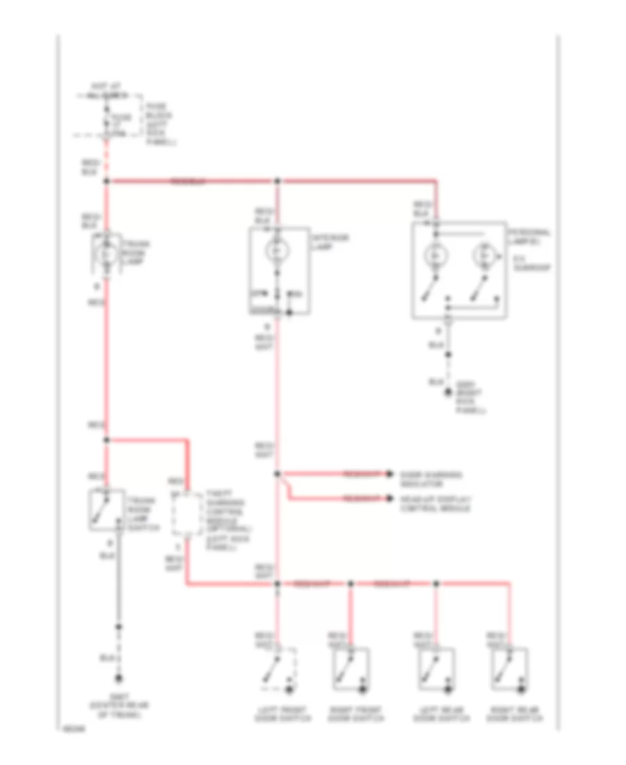
Courtesy Lamps Wiring Diagram for Nissan Altima SE 1994
List of elements for Courtesy Lamps Wiring Diagram for Nissan Altima SE 1994:
- (left kick panel)
- Door
- Door warning indicator
- Ex. sunroof
- Fuse 10a
- Fuse block (left kick panel)
- G203 (right kick panel)
- G407 (center rear of trunk)
- Head-up display control module
- Hot at all times
- Interior lamp
- Left front door switch
- Left rear door switch
- Off
- Personal lamp(s)
- Red
- Right front door switch
- Right rear door switch
- Theft warning control module (optional)
- Trunk room lamp
- Trunk room lamp switch
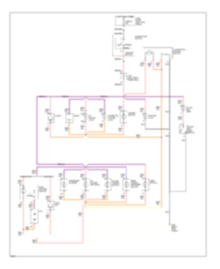
Instrument Illumination Wiring Diagram for Nissan Altima SE 1994
List of elements for Instrument Illumination Wiring Diagram for Nissan Altima SE 1994:
- A/t device illum.
- Asdc switch
- Ashtray illum.
- Auto a/c
- Auto amp.
- Bulbs
- Cd player (optional)
- Cigarette lighter illum.
- Clock
- Combination switch
- Fuse 23 15a
- Fuse block (left kick panel)
- G203 (right kick panel)
- Glove box lamp
- Glove box lamp switch
- Hazard switch
- Head
- Hot at all times
- Ill.
- Illumination control switch
- Instrument cluster
- J/c-6 (left front wheelwell)
- Lighting switch
- Manual a/c
- Nca
- Off
- Park
- Power window switch
- Ptc
- Push control module
- Radio
- Rear window defogger switch
POWER ANTENNA
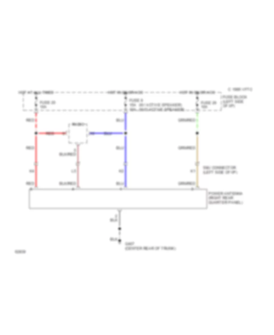
Power Antenna Wiring Diagram for Nissan Altima SE 1994
List of elements for Power Antenna Wiring Diagram for Nissan Altima SE 1994:
- (w/ active speaker) (w/o active speaker)
- 1995 vftc c
- Fuse 20 10a
- Fuse 26 10a
- Fuse 9 15a 10a
- Fuse block (left side of i/p)
- G407 (center rear of trunk)
- Hot at all times
- Hot in on or acc
- Power antenna (right rear quarter panel)
- Radio
- Red
- Smj connector (left side of i/p)
POWER DISTRIBUTION
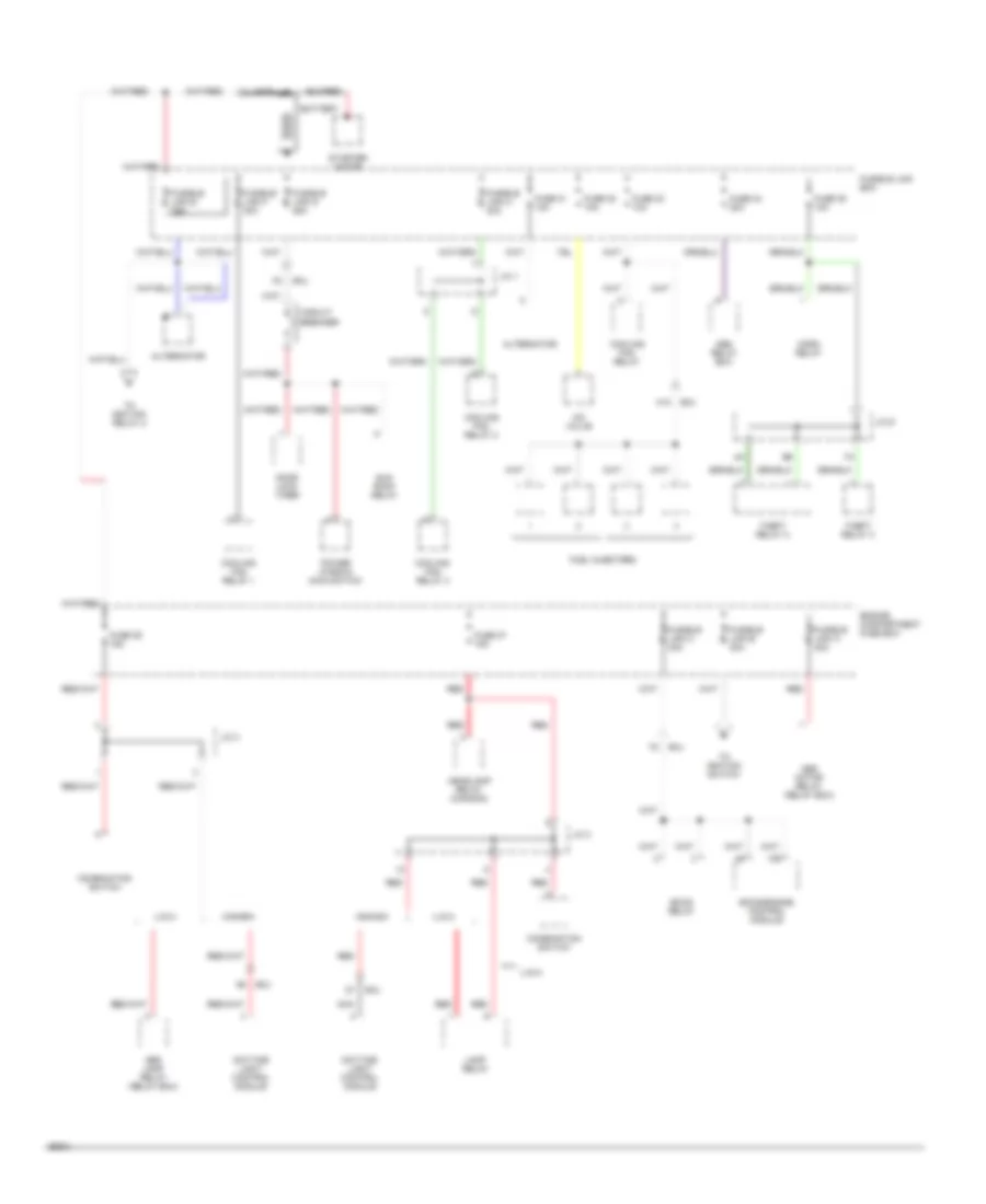
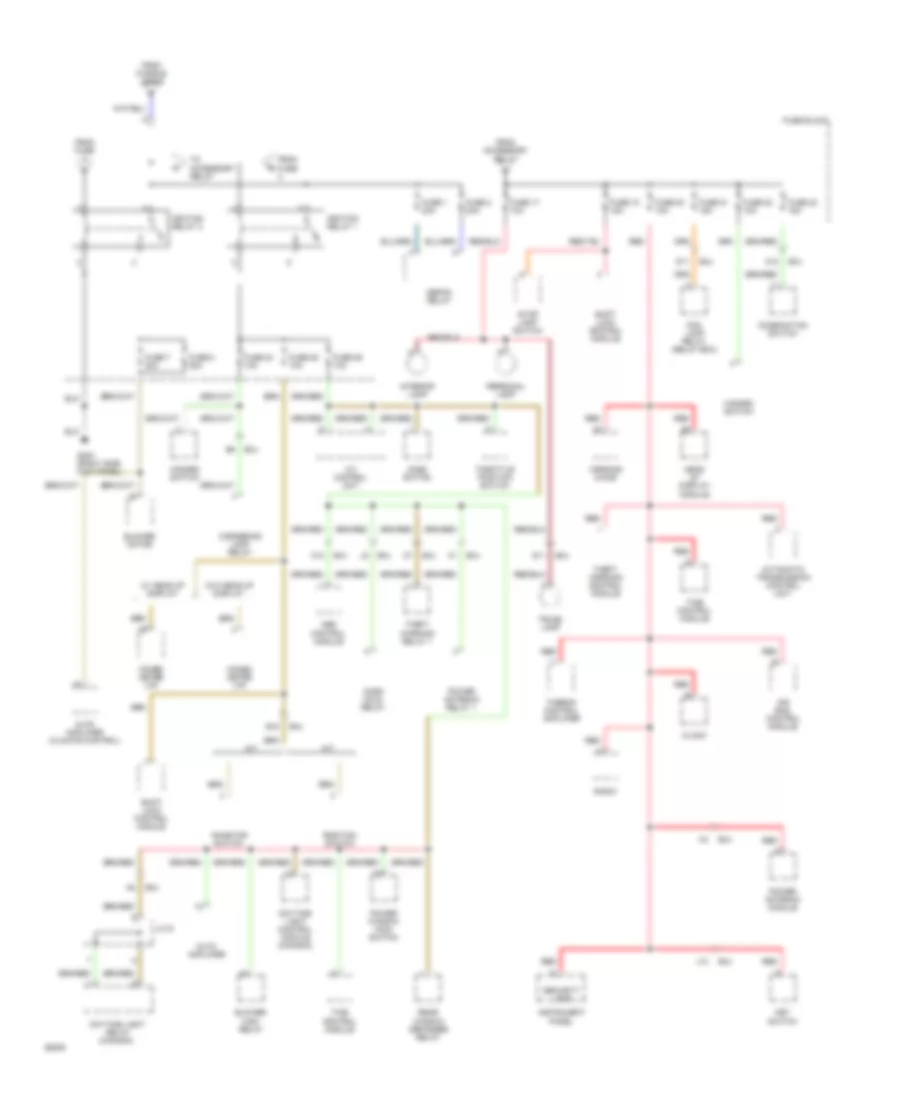
Power Distribution Wiring Diagram (1 of 3) for Nissan Altima SE 1994
List of elements for Power Distribution Wiring Diagram (1 of 3) for Nissan Altima SE 1994:
- Abs lamp relay (relay box)
- Abs motor relay (relay box)
- Abs relay box
- Alternator
- Battery
- Canada
- Circuit breaker
- Combination switch
- Cooling fan relay
- Cooling fan relay 1
- Cooling fan relay 2
- Cooling fan relay 3
- Daytime light control module
- Door lock timer
- Eccs relay
- Eccs/engine control module
- Engine compartment fuse box
- Fuel injectors
- Fuse 31 10a
- Fuse 32 10a
- Fuse 33 10a
- Fuse 34 20a
- Fuse 35 10a
- Fuse 36 15a
- Fuse 37 15a
- Fusible link a 30a
- Fusible link b 30a
- Fusible link box
- Fusible link c 30a
- Fusible link e 75a
- Fusible link f 30a
- Fusible link g 25a
- Fusible link h 30a
- H12
- Headlamp relay (canada)
- Horn relay
- Iac valve
- J/c 1
- J/c 3
- J/c 6
- Lamp relay
- Nca
- Power window main switch
- Red
- Smj
- Starter motor
- Sun roof relay
- Theft relay 2
- Theft relay 3
- To ignition relay 2
- To ignition switch
- U.s.a.
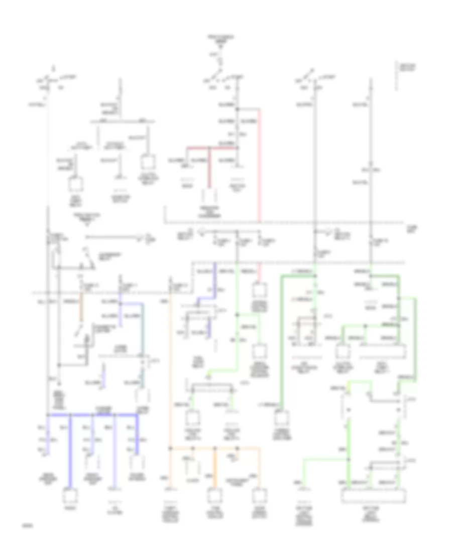
Power Distribution Wiring Diagram (2 of 3) for Nissan Altima SE 1994
List of elements for Power Distribution Wiring Diagram (2 of 3) for Nissan Altima SE 1994:
- (right side kick panel)
- A/t
- Acc
- Accessory relay
- Air bag control module
- Air conditioning relay
- Anti- theft relay
- Anti- theft relay 1
- C11
- Cd player
- Cigarette lighter
- Clock
- Clutch interlock relay
- Cooling fan relay-2
- Cooling fan relay-3
- Daytime light control module (canada)
- Daytime light relay (canada)
- Door mirror switch
- E11
- E12
- Eccs
- Egr & canister control solenoid
- From fusible link b
- From ignition relay 2
- Front speaker amp
- Fuel pump relay
- Fuse 10 15a
- Fuse 11 20a
- Fuse 12 10a
- Fuse 16 10a
- Fuse 3 15a
- Fuse 4 10a
- Fuse 5 10a
- Fuse 6 10a
- Fuse 9 10 or 15a
- Fuse box
- G203
- Ignition coil
- Ignition switch
- Inhibitor switch
- Instrument panel
- J/c 2
- J/c 3
- J/c 4
- J/c 6
- J/c 8
- J12
- K10
- K12
- M/t
- Nca
- Off
- P12
- Power antenna
- Radio
- Rear speaker amp
- Resistor and condenser
- Smj
- Start
- Theft warning control module
- Thermo control amplifier
- Time control module
- To fuse
- To ignition relay 1
- To ignition relay 2
- Washer motor
- Wiper motor
- Wiper relay
- With anti-theft
- Without anti-theft
Power Distribution Wiring Diagram (3 of 3) for Nissan Altima SE 1994
List of elements for Power Distribution Wiring Diagram (3 of 3) for Nissan Altima SE 1994:
- A/t
- A/t control unit
- A12
- Abs control module
- Acsd hold relay
- Acsd switch
- Air bag control module
- Auto amplifier
- Auto amplifier (climate control)
- Automatic transmission control unit
- B12
- Blower high relay
- Blower motor
- C12
- Clock
- Combination switch
- Combo meter (i/p)
- Cornering lamp relay
- D11
- Daytime light control module (canada)
- Daytime light relay (canada)
- Defog relay
- Fog lamp relay (relay box)
- From accessory relay
- From fuse
- From fusible link e
- Fuse 1 20a
- Fuse 17 10a
- Fuse 18 15a
- Fuse 2 20a
- Fuse 20 10a
- Fuse 21 15a
- Fuse 22 10a
- Fuse 23 15a
- Fuse 24 10a
- Fuse 25 10a
- Fuse 26 10a
- Fuse 7 20a
- Fuse 8 20a
- Fuse block
- G203 (right side kick panel)
- Hazard switch
- Head up display module
- Ignition relay 1
- Ignition relay 2
- Inhibitor switch
- Instrument panel
- Interior lamp
- J/c 6
- J10
- Key switch
- M/t
- Personal lamp
- Position switch
- Power antenna module
- Power antenna relay 1
- Power window main switch
- Q11
- Radio
- Rear window defogger relay
- Red
- Security lamp
- Shift lock control module
- Smj
- Stop lamp switch
- Theft warning control module
- Theft warning relay 1
- Thermo control amplifier
- Throttle position switch
- Time control module
- To accessory relay
- Trunk lamp
- W/ head-up display
- W/o head-up display
- Warning chime
POWER DOOR LOCKS
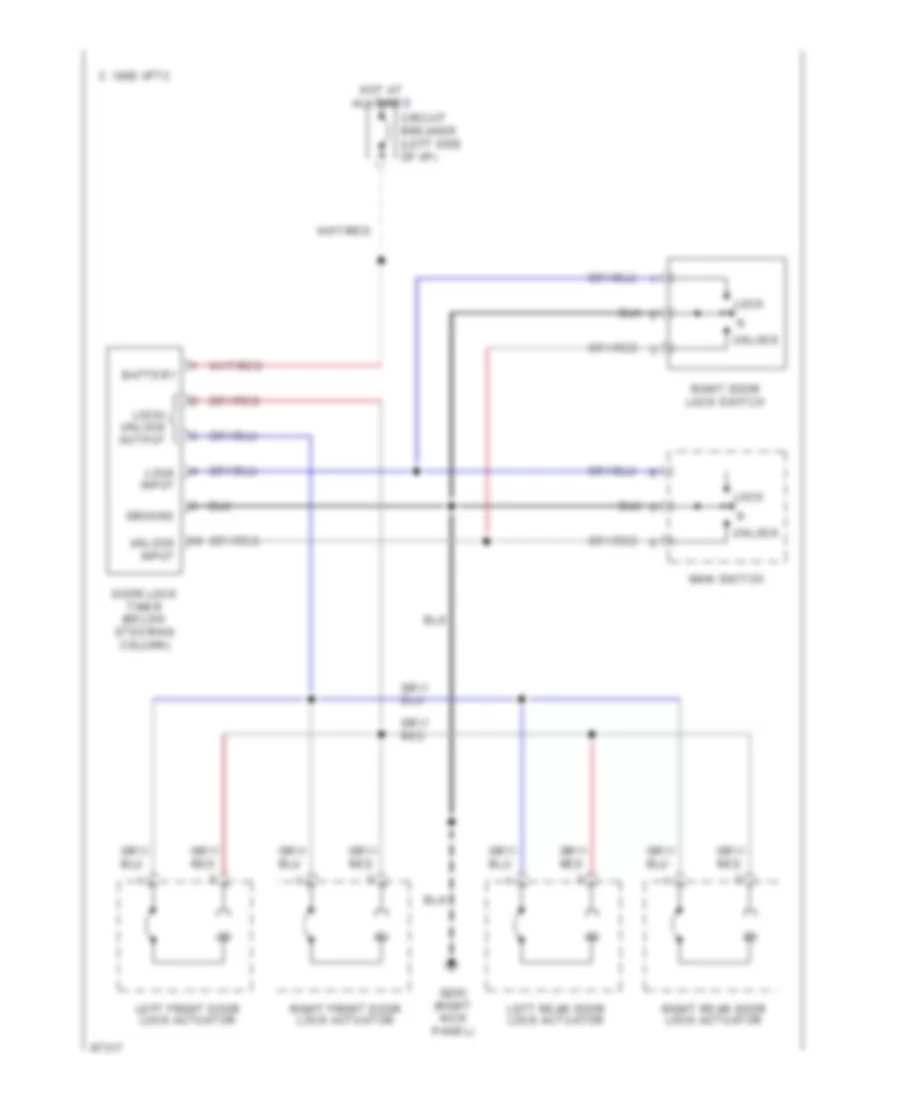
Power Door Lock Wiring Diagram for Nissan Altima SE 1994
List of elements for Power Door Lock Wiring Diagram for Nissan Altima SE 1994:
- Battery
- C 1995 vftc
- Circuit breaker (left side of i/p)
- Door lock timer (below steering column)
- G203 (right kick panel)
- Ground
- Hot at all times
- Left front door lock actuator
- Left rear door lock actuator
- Lock
- Lock input
- Lock/ unlock output
- Main switch
- Right door lock switch
- Right front door lock actuator
- Right rear door lock actuator
- Unlock
- Unlock input
POWER MIRRORS
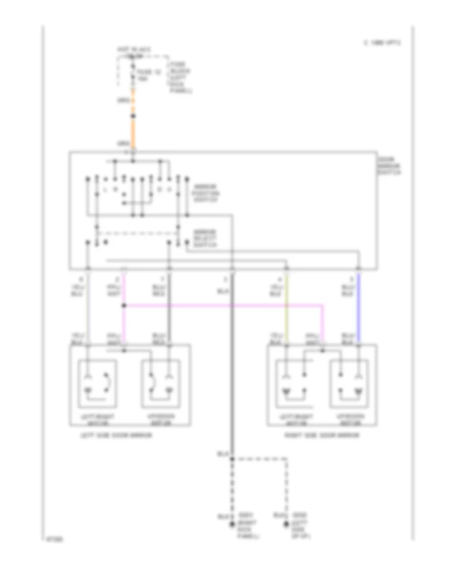
Power Mirror Wiring Diagram for Nissan Altima SE 1994
List of elements for Power Mirror Wiring Diagram for Nissan Altima SE 1994:
- (left side of i/p)
- (right kick panel)
- C 1995 vftc
- Door mirror switch
- Fuse 12 10a
- Fuse block (left kick panel)
- G202
- G203
- Hot in acc or on
- Left side door mirror
- Left/right motor
- Mirror position switch
- Mirror select switch
- Right side door mirror
- Up/down motor
POWER TOP/SUNROOF
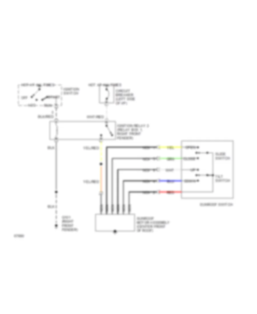
Power Top/Sunroof Wiring Diagrams for Nissan Altima SE 1994
List of elements for Power Top/Sunroof Wiring Diagrams for Nissan Altima SE 1994:
- Acc
- Circuit breaker (left side of i/p)
- Close
- Down
- G101 (right front fender)
- Hot at all times
- Ignition relay 2 (relay box 1, right front fender)
- Ignition switch
- Nca
- Off
- Open
- Red
- Run
- Slide switch
- Start
- Sunroof motor assembly (center front of roof)
- Sunroof switch
- Tilt switch
POWER WINDOWS
Power Window Wiring Diagram for Nissan Altima SE 1994
List of elements for Power Window Wiring Diagram for Nissan Altima SE 1994:
- 1995 vftc c
- Battery
- Circuit breaker (left side of i/p)
- Data sig
- Door lock
- Door lock system
- Down power
- Fuse 10a
- Fuse block (left side of i/p)
- G203 (right kick panel)
- G308 (left "b" pillar)
- Ground
- Hot at all times
- Hot in run or start
- Ignition
- Illum.
- Interior light system
- Left front power window motor
- Left rear
- Left rear power window amplifier (left rear door)
- Left rear power window motor
- Left rear power window switch
- Pnk
- Power
- Power (lock sig)
- Power window main switch
- Pwr (lock sig)
- Pwr (lock sig) up power
- Right front power window amplifier (right front door)
- Right front power window motor
- Right front power window switch
- Right rear power window amplifier (right rear door)
- Right rear power window motor
- Right rear power window switch
- Right sig
- Up power
RADIO
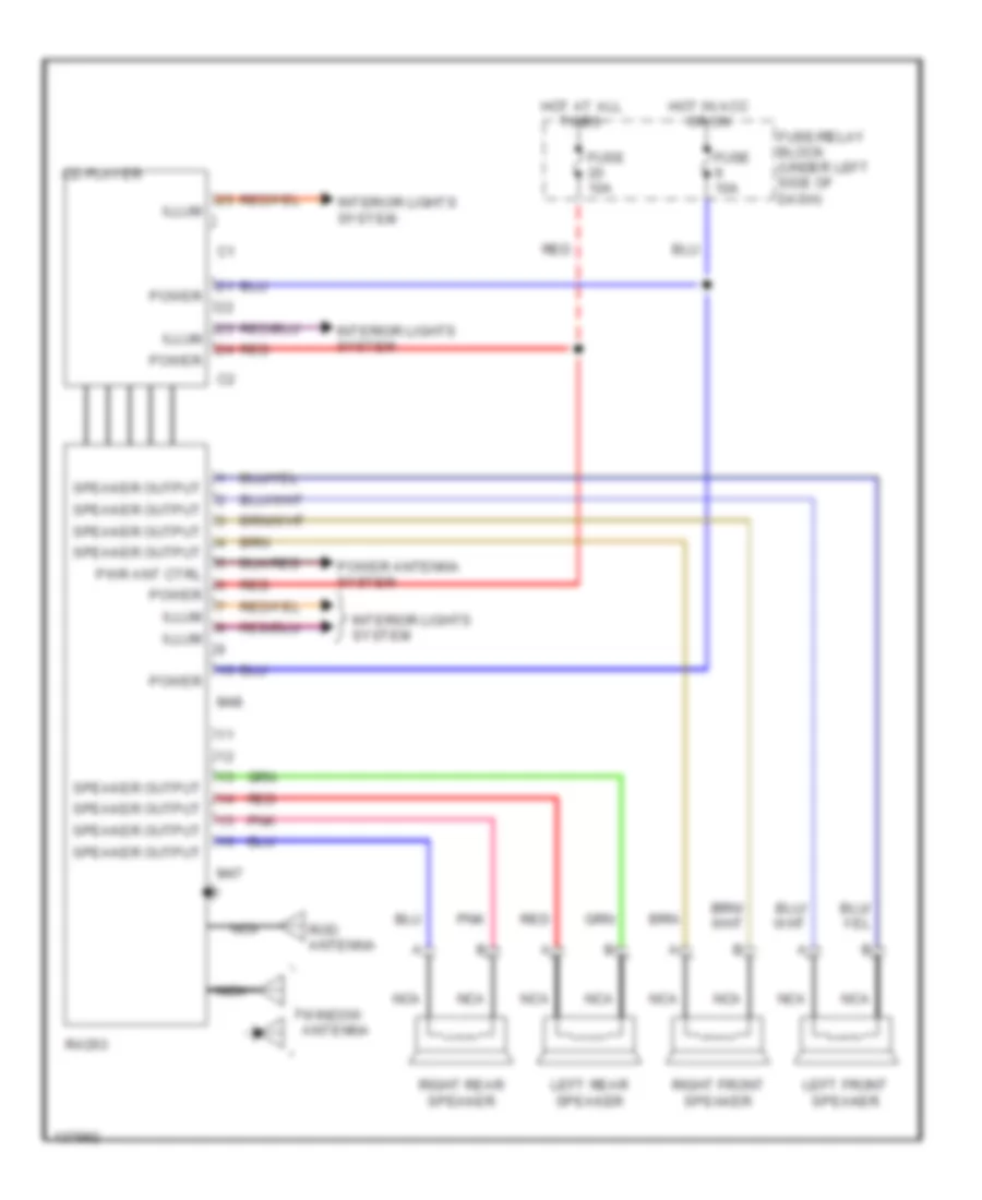
Radio Wiring Diagrams, Base Radio for Nissan Altima SE 1994
List of elements for Radio Wiring Diagrams, Base Radio for Nissan Altima SE 1994:
- Cd player
- Fuse 10a
- Fuse/relay block (under left side of dash)
- Hot at all times
- Hot in acc or on
- Illum
- Interior lights system
- Left front speaker
- Left rear speaker
- M47
- M48
- Nca
- Pnk
- Power
- Power antenna system
- Pwr ant ctrl
- Radio
- Red
- Right front speaker
- Right rear speaker
- Rod antenna
- Speaker output
- Window antenna
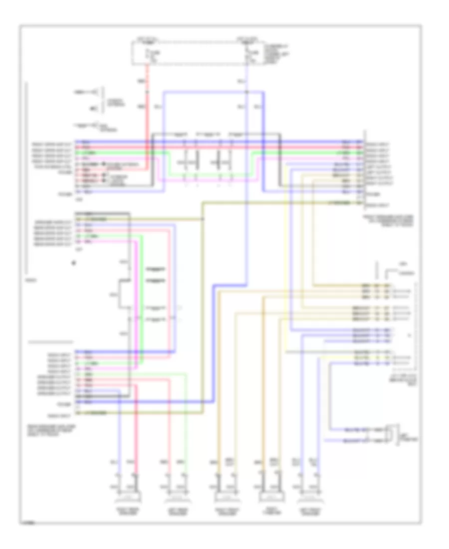
Radio Wiring Diagrams, Premium Radio for Nissan Altima SE 1994
List of elements for Radio Wiring Diagrams, Premium Radio for Nissan Altima SE 1994:
- Canada
- Front speaker amplifier (on underside of rear shelf, in trunk)
- Front spkr amp out
- Fuse 10a
- Fuse 15a
- Fuse/relay block (under left side of dash)
- Hot at all times
- Hot in acc or on
- Interior lights system
- J/c 7 (or j/c 8) (behind glove box)
- Left front speaker
- Left output
- Left rear speaker
- Left tweeter
- M47
- M48
- Nca
- Pnk
- Power
- Power antenna system
- Pwr antenna ctrl
- Radio
- Radio input
- Rear speaker amplifier (on underside of rear shelf, in trunk)
- Rear spkr amp out
- Red
- Right front speaker
- Right output
- Right rear speaker
- Right tweeter
- Rod antenna
- Speaker amps out
- Speaker output
- Usa
- Window antenna
SHIFT INTERLOCKS
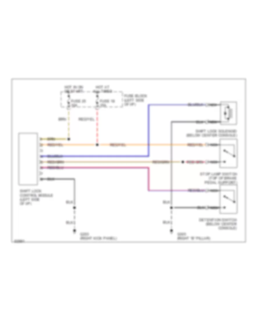
Shift Interlock Wiring Diagram for Nissan Altima SE 1994
List of elements for Shift Interlock Wiring Diagram for Nissan Altima SE 1994:
- Detention switch (below center console)
- Fuse 18 15a
- Fuse 25 10a
- Fuse block (left side of i/p)
- G203 (right kick panel)
- G305 (right "b" pillar)
- Hot at all times
- Hot in on or start
- Nca
- Shift lock control module (left side of i/p)
- Shift lock solenoid (below center console)
- Stop lamp switch (top of brake pedal support)
STARTING/CHARGING
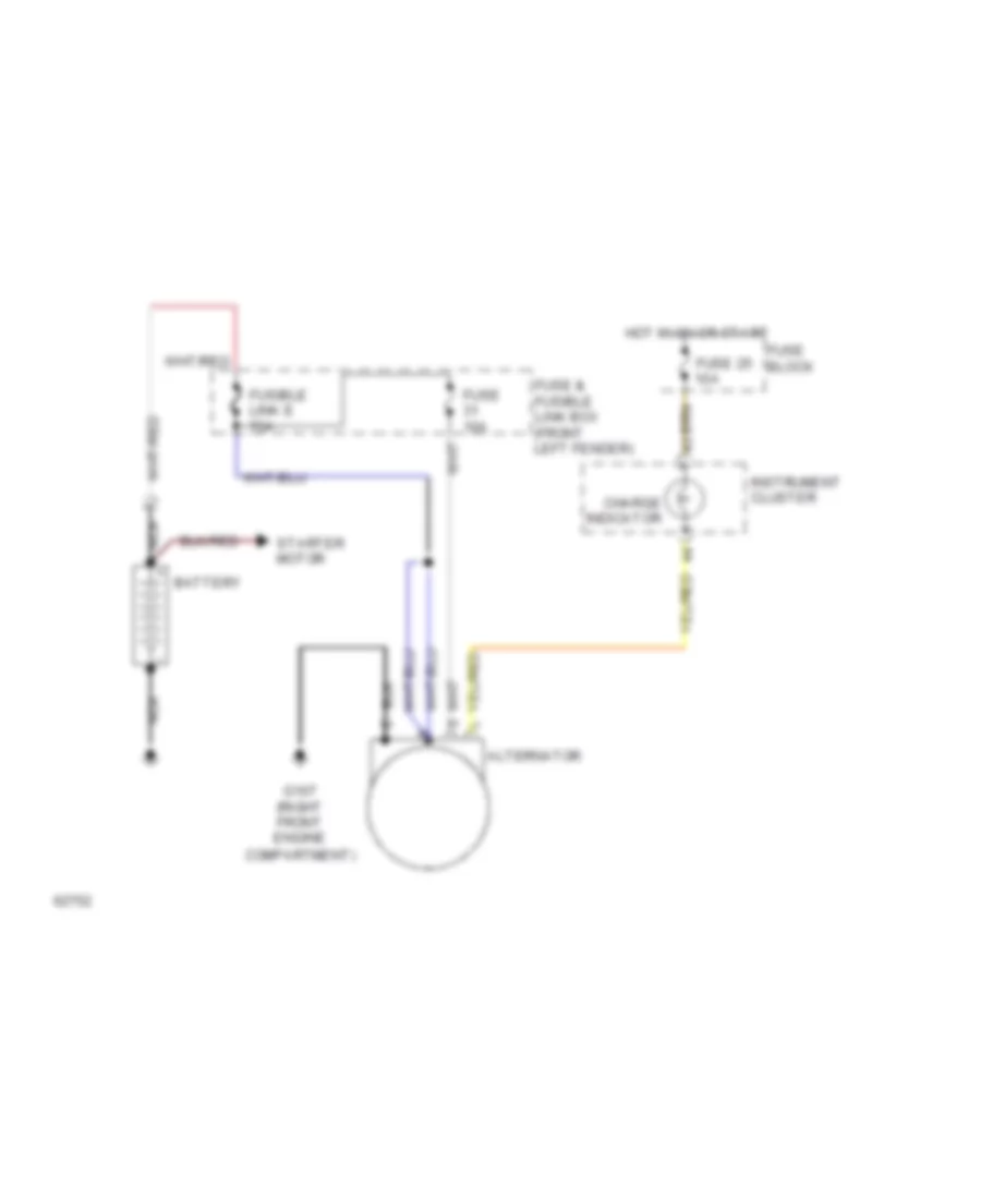
Charging Wiring Diagram for Nissan Altima SE 1994
List of elements for Charging Wiring Diagram for Nissan Altima SE 1994:
- Alternator
- Battery
- Charge indicator
- Fuse & fusible link box (front left fender)
- Fuse 10a
- Fuse 25 10a
- Fuse block
- Fusible link e 75a
- G107 (right front engine compartment)
- Hot in on or start
- Instrument cluster
- Nca
- Starter motor
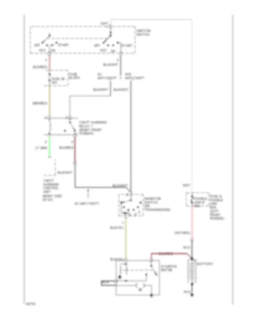
Starting Wiring Diagram, A/T for Nissan Altima SE 1994
List of elements for Starting Wiring Diagram, A/T for Nissan Altima SE 1994:
- (right side of i/p)
- Acc
- Battery
- Fuse & fusible link box (left front fender)
- Fuse 26 10a
- Fuse block
- Fusible link b 30a
- Ignition switch
- Inhibitor switch (on transmission)
- Nca
- Off
- Start
- Starter motor
- Theft warning control unit
- Theft warning relay 1 (right front fender)
- W/ anti-theft
- W/o anti-theft
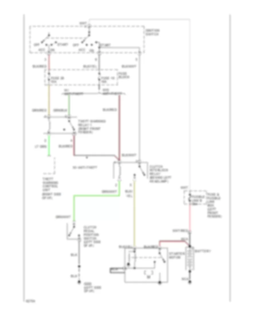
Starting Wiring Diagram, M/T for Nissan Altima SE 1994
List of elements for Starting Wiring Diagram, M/T for Nissan Altima SE 1994:
- (right side of i/p)
- Acc
- Battery
- Clutch interlock relay (behind left headlamp)
- Clutch pedal position switch (left side of i/p)
- Fuse & fusible link box (left front fender)
- Fuse 16 10a
- Fuse 26 10a
- Fuse block
- Fusible link b 30a
- G202 (left side of i/p)
- Ignition switch
- Nca
- Off
- Start
- Starter motor
- Theft warning control unit
- Theft warning relay 1 (right front fender)
- W/ anti-theft
- W/o anti-theft
SUPPLEMENTAL RESTRAINTS
Supplemental Restraint Wiring Diagram for Nissan Altima SE 1994
List of elements for Supplemental Restraint Wiring Diagram for Nissan Altima SE 1994:
- Air bag control module (below center of i/p)
- Air bag deployment circuits
- Air bag ind.
- Data link conn.
- Data link connector for consult (left side of i/p)
- Front crash zone sensor (right front fender)
- Fuse 20 10a
- Fuse 25 10a
- Fuse 5 10a
- Fuse block (left side of i/p)
- G203 (right kick panel)
- G308 (left "b" pillar)
- Ground
- Head-up display control module
- Hot at all times
- Hot in on or start
- Instrument cluster
- Left airbag module (top of steering column)
- Left front door switch
- Nca
- Power
- Red
- Right airbag module 1 (right side of i/p)
- Right airbag module 2 (right side of i/p)
- Self diag. enable
- Sensor input
- Sensor inputs
- Spiral cable
- Time control module (at base of steering column)
- Tunnel and safing sensor (below center console)
- W/ hud
- W/o hud
- Warning lamp
TRANSMISSION
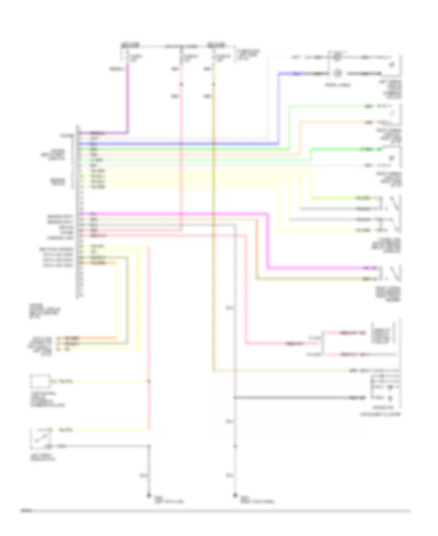
Transmission Wiring Diagram for Nissan Altima SE 1994
List of elements for Transmission Wiring Diagram for Nissan Altima SE 1994:
- 1995 vftc c
- A/t control unit (behind right kick panel)
- A/t fluid temp. sensor
- All times
- Ascd control unit (behind left side of dash)
- Automatic transaxle
- Backup lights
- Cruise
- Data link connector (for consult) (below left side of i/p)
- Dropping resistor (left front strut tower)
- Eccs control module (behind center console)
- Fuse 10a
- Fuse block (left kick panel)
- G131 (intake manifold)
- G203 (right kick panel)
- G308 (left side b pillar)
- Hot at
- Hot in on or start
- Hud control module
- Ind.
- Inhibitor switch (left transaxle)
- Instrument cluster
- Line press. sol. valve
- Nca
- O.d. off ind.
- O/d clutch sol. valve
- Overdrive switch
- Red
- Revolution sensor
- Shift sol. valve a
- Shift sol. valve b
- Speedo- meter
- Speedometer
- Tachometer
- Tcc sol. valve
- Throttle position sensor (on throttle body)
- Throttle position switch (on throttle body)
- Vehicle speed sensor (on transaxle)
- W/ head-up display
- W/o head-up display
- Wot
WARNING SYSTEMS
Warning System Wiring Diagrams for Nissan Altima SE 1994
List of elements for Warning System Wiring Diagrams for Nissan Altima SE 1994:
- "b" pillar)
- (bottom of left
- (left i/p)
- Air bag control unit
- Block (left
- Combination switch
- Fuse
- Fuse 10a
- Fuse 15a
- G200
- G308
- Head
- Head up display control module
- Hot at all times
- Hot in on or start
- I/p)
- Instrument cluster
- J/c-6 (left front wheel- well)
- Key switch
- Left front door switch
- Lighting switch
- Off
- Park
- Red
- Seat belt ind.
- Seat belt switch
- Time control unit (at base of steering column)
- Warning chime
WIPER/WASHER
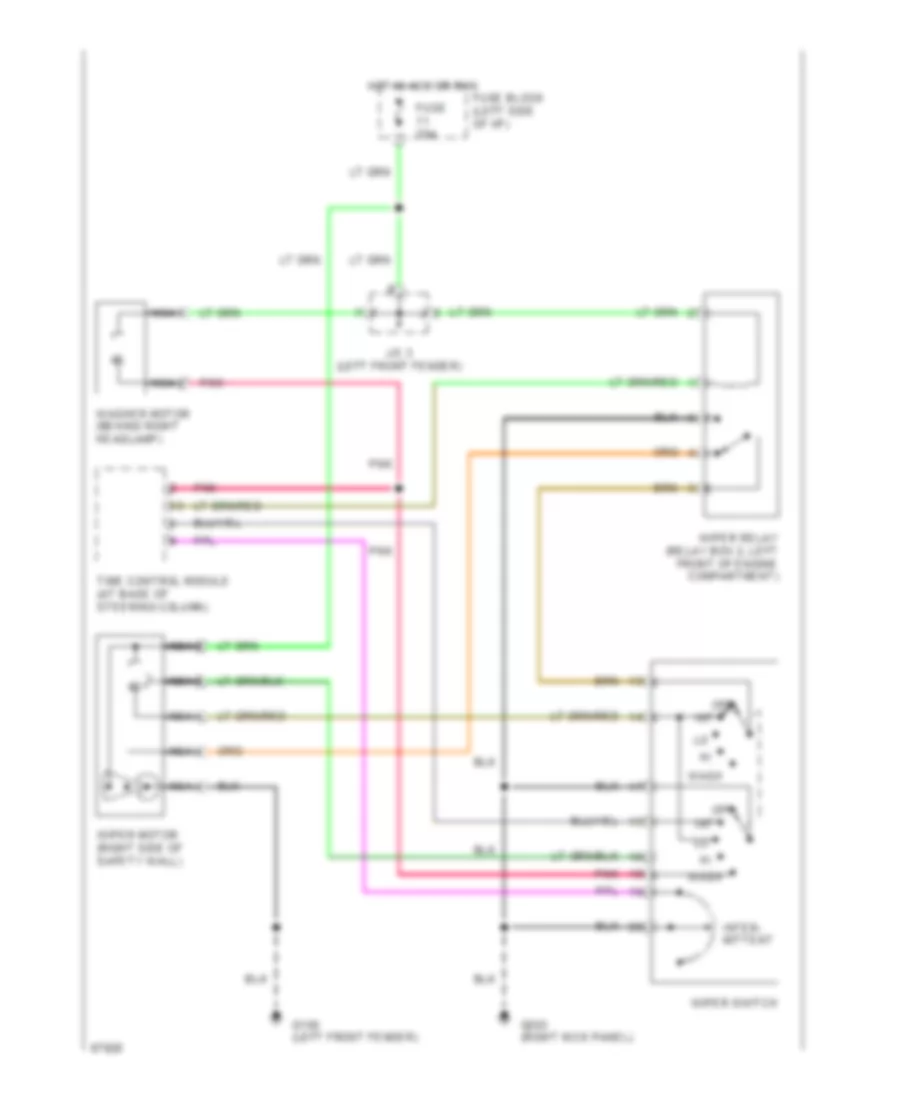
Wiper/Washer Wiring Diagram for Nissan Altima SE 1994
List of elements for Wiper/Washer Wiring Diagram for Nissan Altima SE 1994:
- Fuse 20a
- Fuse block (left side of i/p)
- G100 (left front fender)
- G203 (right kick panel)
- Hot in acc or run
- Int
- Inter- mittent
- J/c 3 (left front fender)
- Nca
- Off
- Pnk
- Time control module (at base of steering column)
- Wash
- Washer motor (behind right headlamp)
- Wiper motor (right side of safety wall)
- Wiper relay (relay box 2, left front of engine compartment)
- Wiper switch

 Čeština
 Dansk
Dansk Deutsch
 Ελληνικά
 English
 English
 Español
 Suomi
Suomi Français
 Français
 עברית
עברית Magyar
 Italiano
 日本語
日本語 한국어
한국어 Nederlands
 Polski
 Português
 Português
 Română
 Русский
 Slovenčina
 Slovenščina
 Svenska
 Türkçe
 中文 (中国)