AIR CONDITIONING
2.4L VIN 5
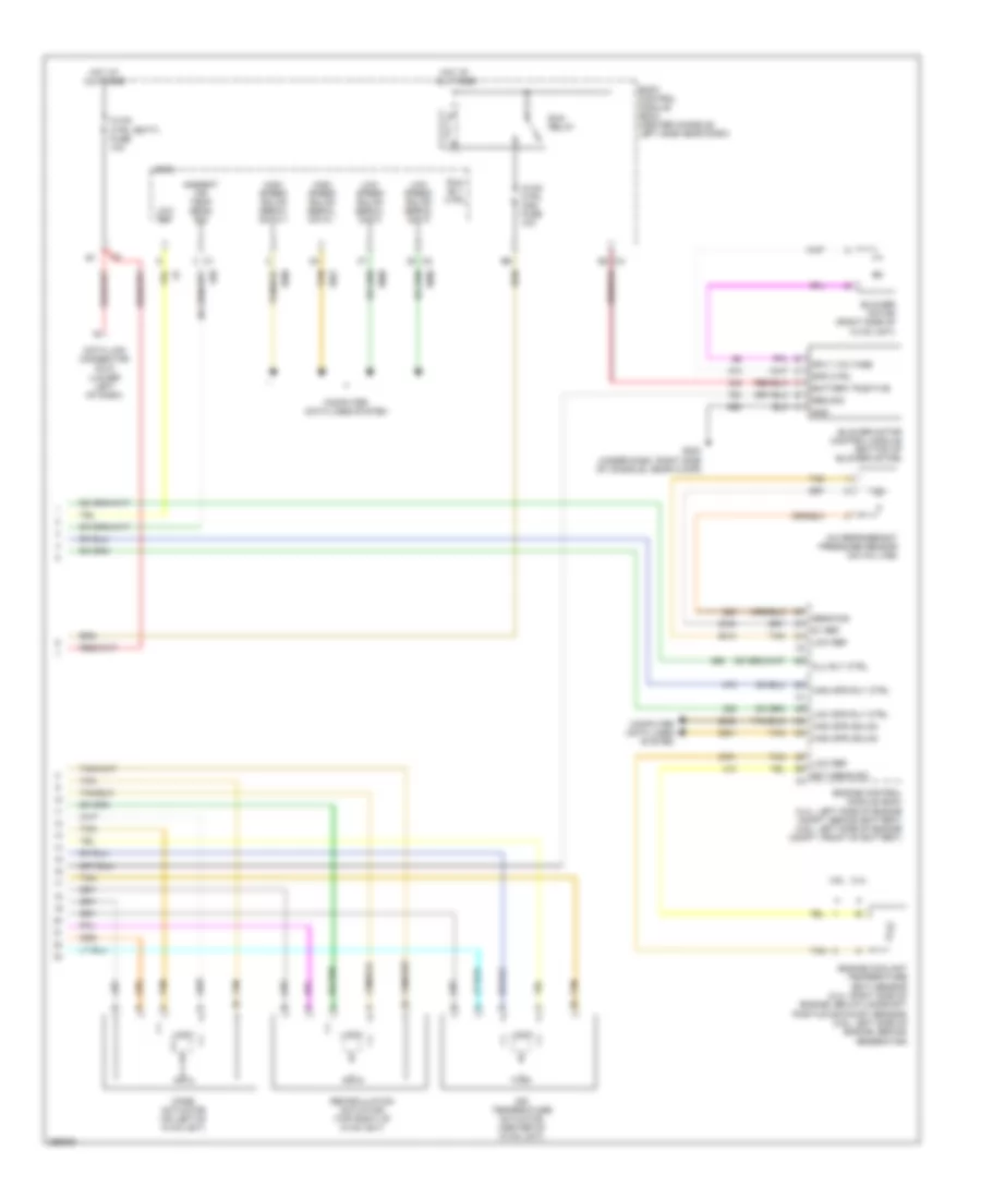
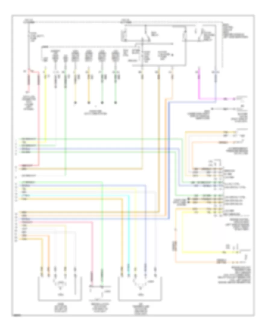
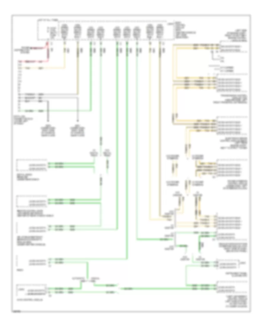
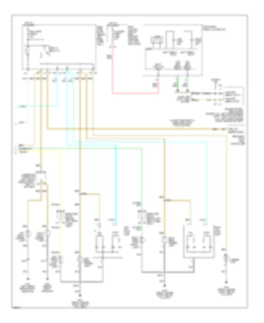
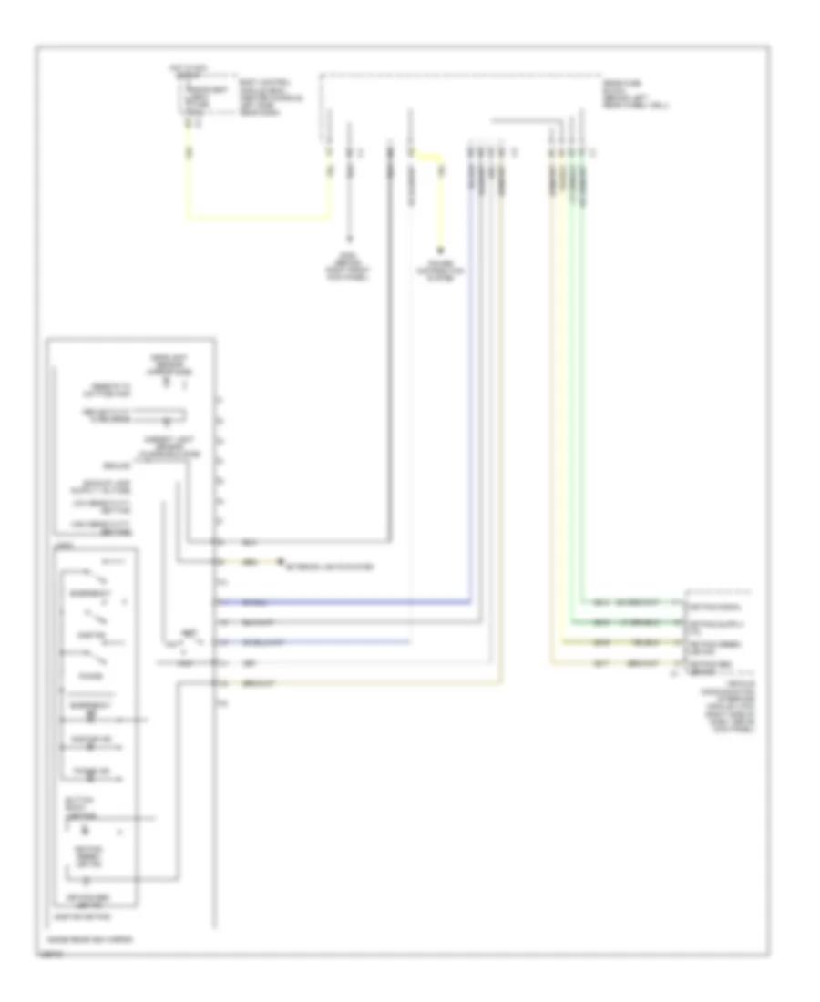
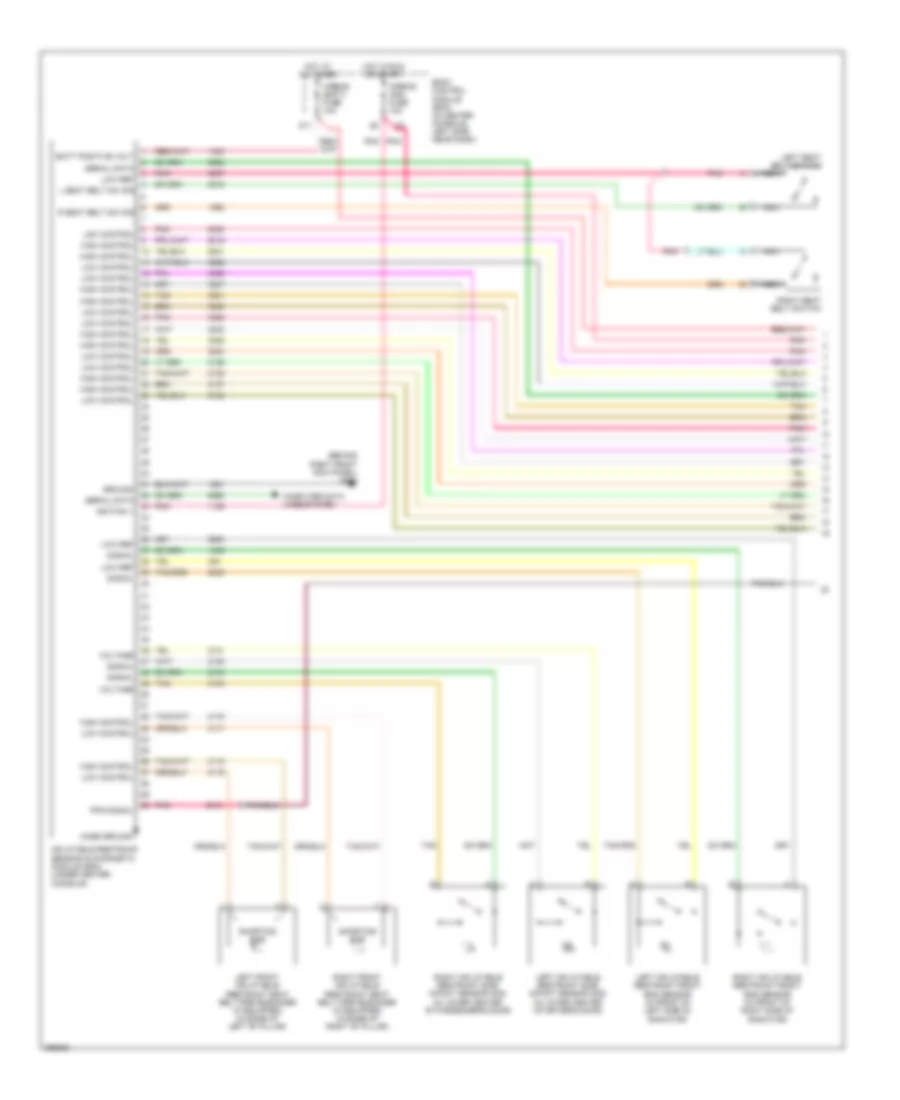
2.4L VIN 5, Automatic A/C Wiring Diagram (1 of 2) for Saturn Aura XR 2007
 https://portal-diagnostov.com/license.html
Automotive Electricians Portal FZCO
Automotive Electricians Portal FZCO
https://portal-diagnostov.com/license.html
https://portal-diagnostov.com/license.html
Automotive Electricians Portal FZCO
Automotive Electricians Portal FZCO
List of elements for 2.4L VIN 5, Automatic A/C Wiring Diagram (1 of 2) for Saturn Aura XR 2007:
- (2.4l)
- (2.4l) s150
- (2.4l) s153
- (not used)
- 5 volt ref
- A/c clu fuse 1 10a
- A/c clutch relay
- A/c compressor clutch (lower left, front of engine, part of a/c compressor)
- A/c request ind
- A/c request switch
- A11 c2
- A2 c1
- A5 c2
- Air temp dr pos sig
- Ambient air temperature sensor (left front impact bar, behind grille)
- Auto
- B10
- Bas pmp fuse 20a
- Battery positive
- C1 e3
- C2 b10
- C3 b9
- Computer data lines system
- Cool fan 1 fuse 17 30a
- Cool fan 2 fuse 18 30a
- Cool/ fan 1 relay
- Cool/ fan 2 relay
- Cool/fan ser/par relay
- Defog ind
- Defog switch
- Door position sig
- Dr ctrl a
- Dr ctrl b
- E1 c2
- E8 c1
- Fresh air ind
- Fresh air switch
- G106 (2.4l: rear of engine, near pnp switch)
- G201 (under dash, right side of console, near floor)
- Gnd
- Heater coolant pump (middle rear of engine)
- High
- Hot at all times
- Hot in run or start
- Hvac control module
- Ign 3 vol
- Left cooling fan (left rear of radiator)
- Left cooling fan diode (2.4l)
- Logic
- Low blower motor switch
- Low ref
- Lower air temperature sensor (behind right console access panel)
- Lower air temperature switch
- Mode dr pos sig
- Mode switch
- Off
- Pnk
- Power distribution system
- Recir door ctrl
- Recirculation ind
- Recirculation switch
- Req sig
- Right cooling fan (right rear of radiator)
- Right cooling fan diode (2.4l)
- Serial data
- Signal
- Starter generator control module (sgcm) (left front engine compt)
- Tan
- Underhood fuse block (left side of engine compt, next to battery)
- Upper air temperature sensor (inside left center a/c duct)
- Upper air temperature switch
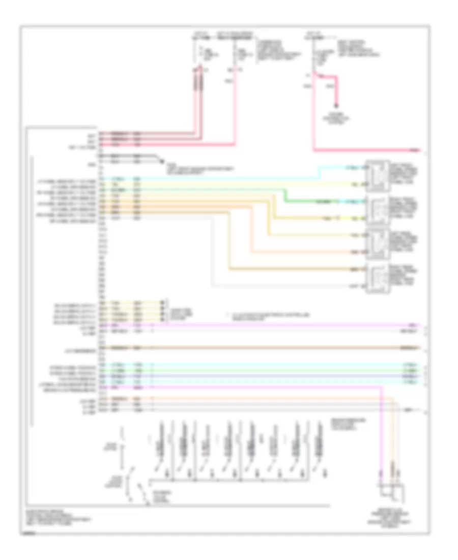
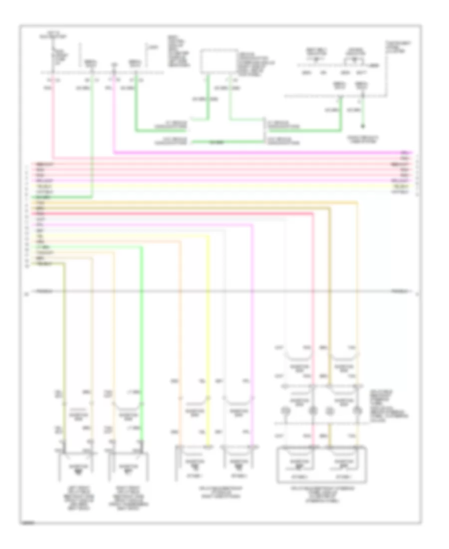
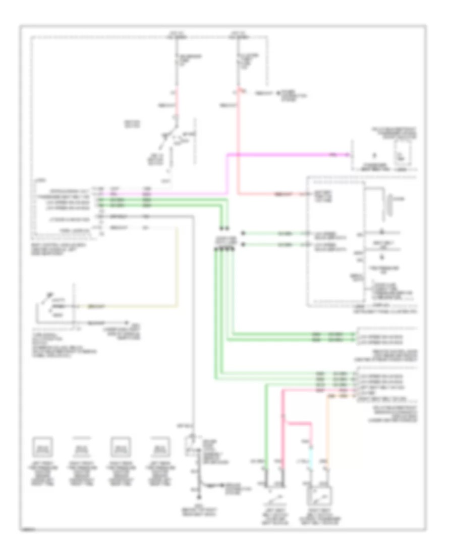
2.4L VIN 5, Automatic A/C Wiring Diagram (2 of 2) for Saturn Aura XR 2007
List of elements for 2.4L VIN 5, Automatic A/C Wiring Diagram (2 of 2) for Saturn Aura XR 2007:
- 2.4l
- 3.6l
- 5v ref
- A/c refrigerant pressure sensor (on a/c line)
- Air temperature actuator (center of hvac unit)
- Ambient air temp sens sig
- Battery positive
- Blower motor (right side of hvac unit)
- Blower motor control module (bottom of blower motor)
- Body control module (bcm) (center console, left side near dash)
- Clu rly ctrl
- Computer data lines system
- Data link connector (dlc) (lower left of dash)
- E2 c4
- Ect sens sig c3
- Engine control module (ecm) (2.4l: left side of engine compt, behind battery) (3.6l: left side of engine compt, front of battery)
- Engine coolant temperature (ect) sensor (2.4l: right side of engine, below camshaft position exhaust sensor) (3.6l: left side of engine, behind generator)
- G203 (under dash, right side of console, near floor)
- Gnd
- High spd gmlan
- High spd rly ctrl c1
- High speed gmlan serial data +
- High speed gmlan serial data -
- Hot at all times
- Hvac ctrl (batt) fuse 10a
- Hvac ctrl (ign) fuse 10a
- Logic
- Low ref
- Low ref c3
- Low spd rly ctrl
- Low speed gmlan serial data
- Mode actuator (on left of hvac unit)
- Recirculation actuator (top right of hvac unit)
- Req sig
- Run relay
- Run rly ctrl
- Sens sig
- Spd ctrl
- Sply voltage
- Tan
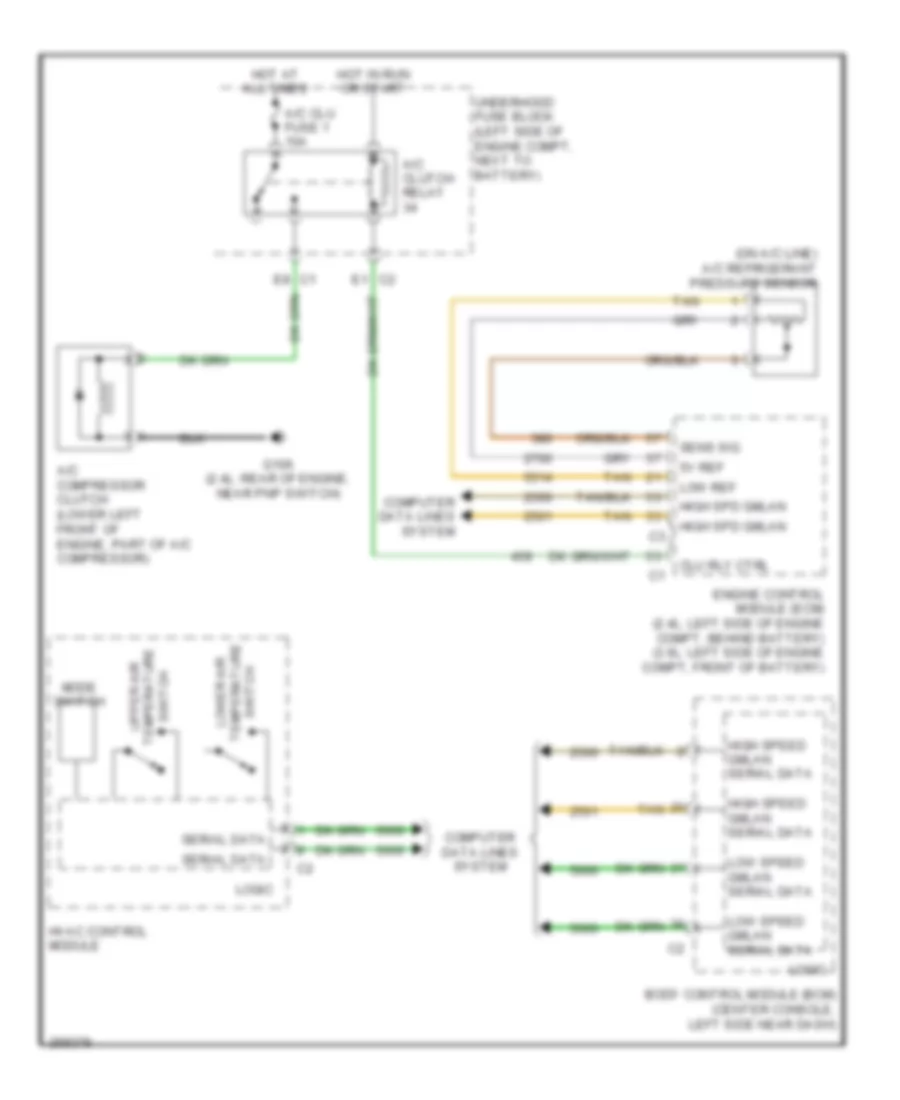
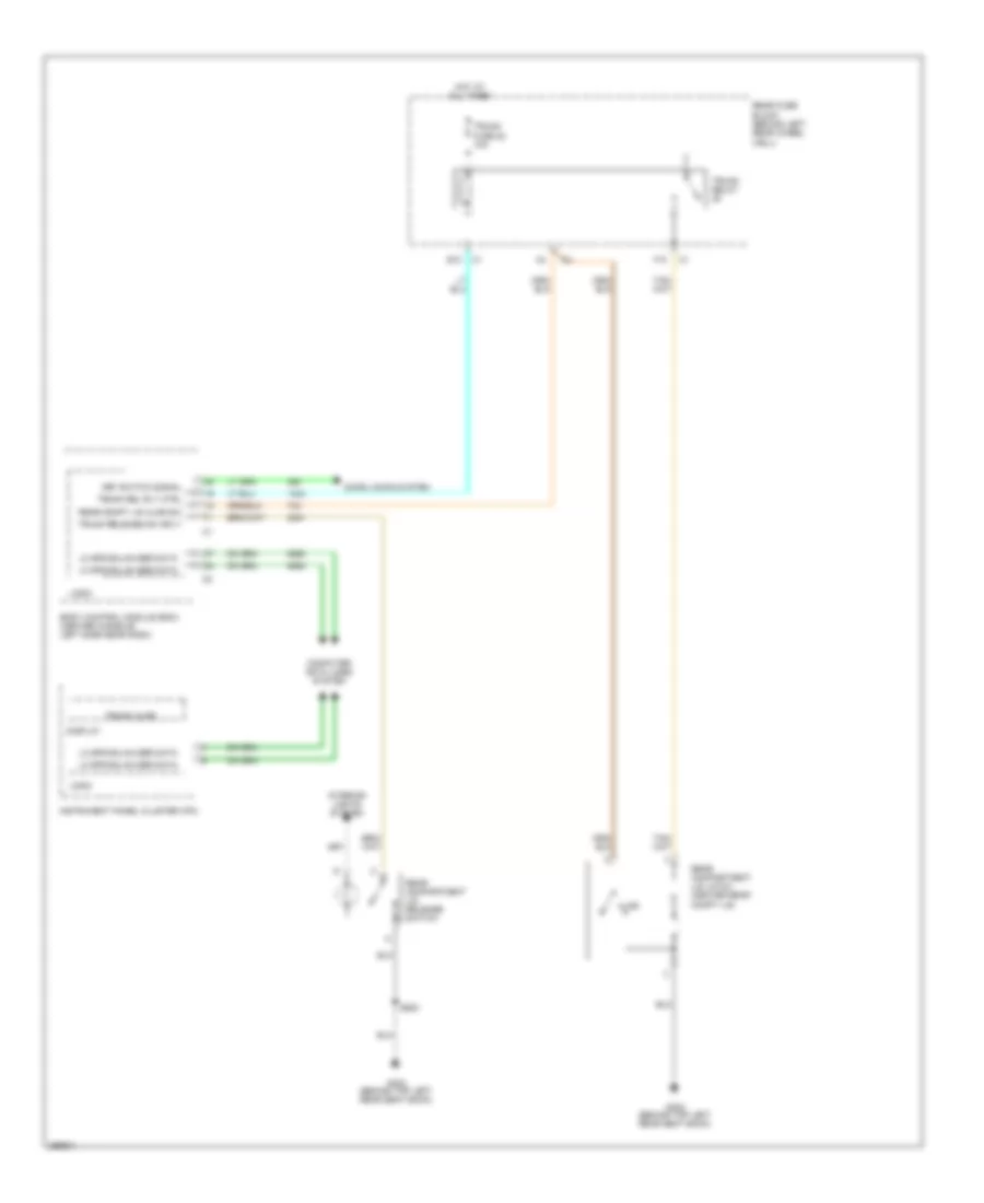
2.4L VIN 5, Compressor Wiring Diagram, with Auto A/C for Saturn Aura XR 2007
List of elements for 2.4L VIN 5, Compressor Wiring Diagram, with Auto A/C for Saturn Aura XR 2007:
- (on a/c line) a/c refrigerant pressure sensor
- 5v ref
- A/c clu fuse 1 10a
- A/c clutch relay
- A/c compressor clutch (lower left front of engine, part of a/c compressor)
- Body control module (bcm) (center console, left side near dash)
- C1 e8
- C2 e1
- Clu rly ctrl
- Computer data lines system
- Engine control module (ecm) (2.4l: left side of engine compt, behind battery) (3.6l: left side of engine compt, front of battery)
- G106 (2.4l: rear of engine, near pnp switch)
- High spd gmlan
- High speed gmlan serial data
- Hot at all times
- Hot in run or start
- Hvac control module
- Logic
- Low ref
- Low speed gmlan serial data
- Lower air
- Mode switch
- Sens sig
- Serial data
- Switch temperature upper air
- Tan
- Temperature switch
- Underhood fuse block (left side of engine compt, next to battery)
3.5L VIN N
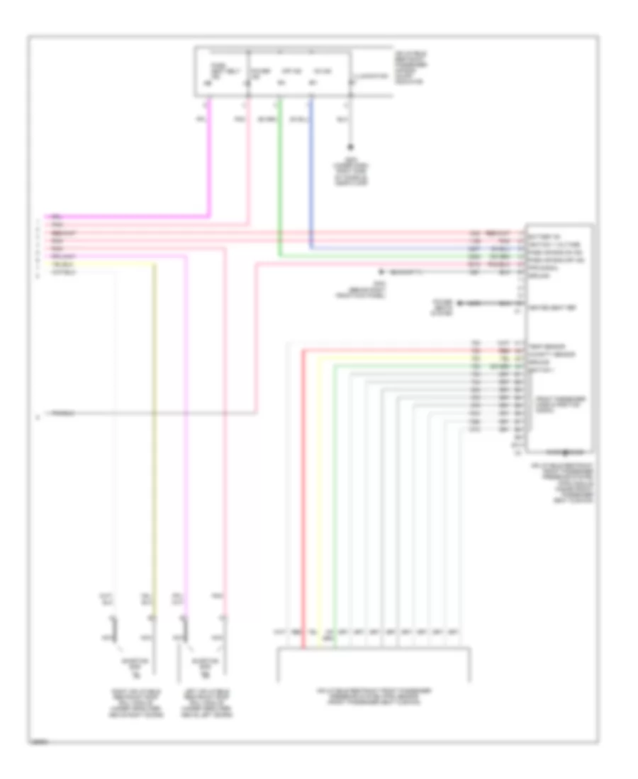
3.5L VIN N, Compressor Wiring Diagram, with Manual A/C for Saturn Aura XR 2007
List of elements for 3.5L VIN N, Compressor Wiring Diagram, with Manual A/C for Saturn Aura XR 2007:
- (on a/c line) a/c refrigerant pressure sensor
- 3.5l 3.6l
- 5v ref
- A/c clu fuse 1 10a
- A/c clutch relay
- A/c compressor clutch (lower left, front of engine, part of a/c compressor)
- A/c req sig
- A/c request ind
- A/c request switch
- Body control module (bcm) (center console, left side near dash)
- Clu rly ctrl
- Computer data lines system
- E1 c2
- E8 c1
- Engine control module (ecm) (left side of engine compt, front of battery)
- G106 (3.5l: rear of engine, above oil filter)
- High spd gmlan
- High speed gmlan serial data
- Hot at all times
- Hot in run or start
- Hvac control module
- Logic
- Low ref
- Low speed gmlan serial data
- Mode switch
- Sens sig
- Tan
- Temperature control switch
- Underhood fuse block (left side of engine compt, next to battery)
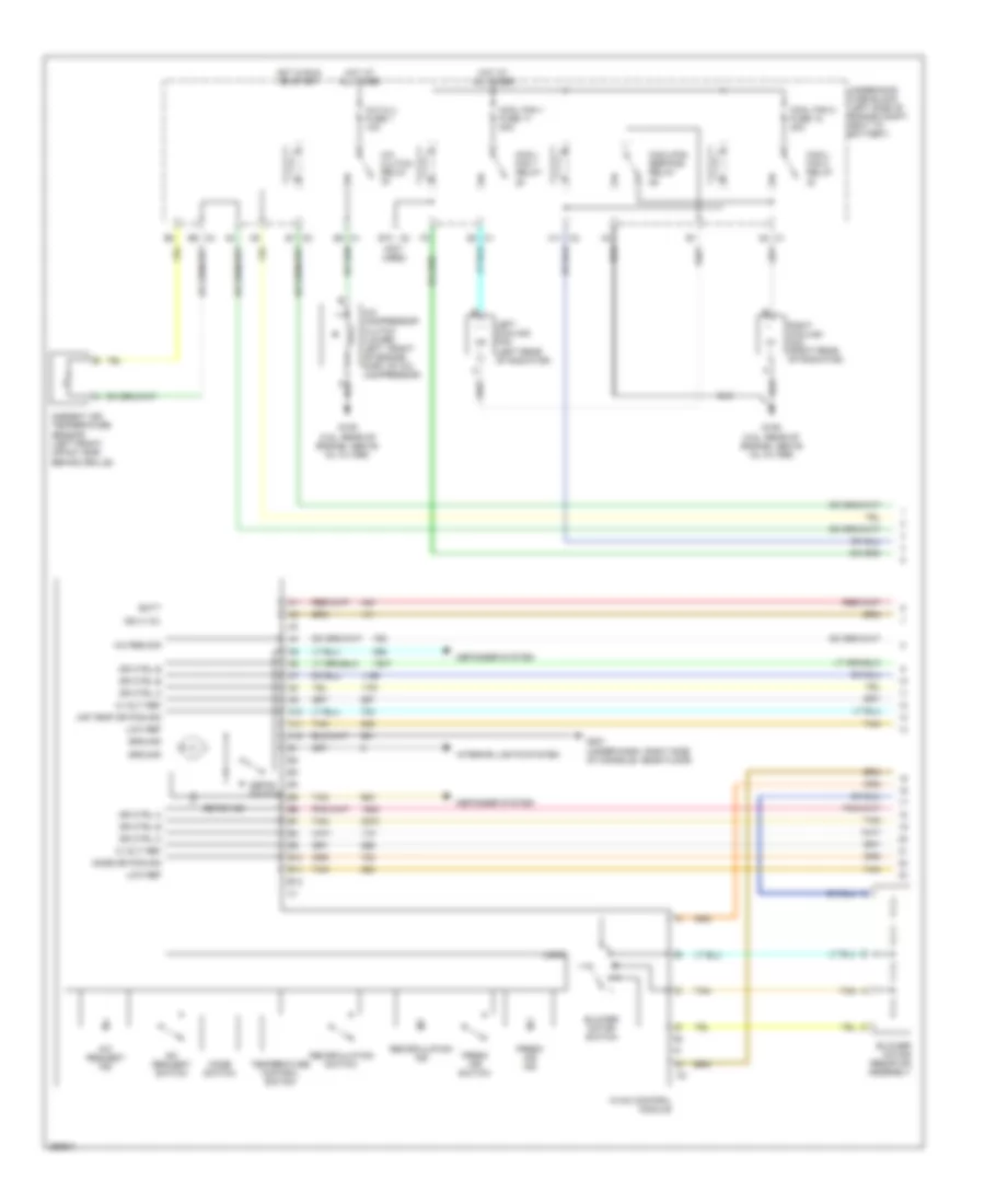
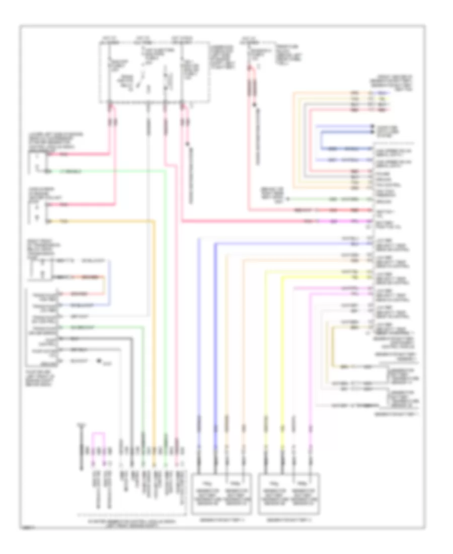
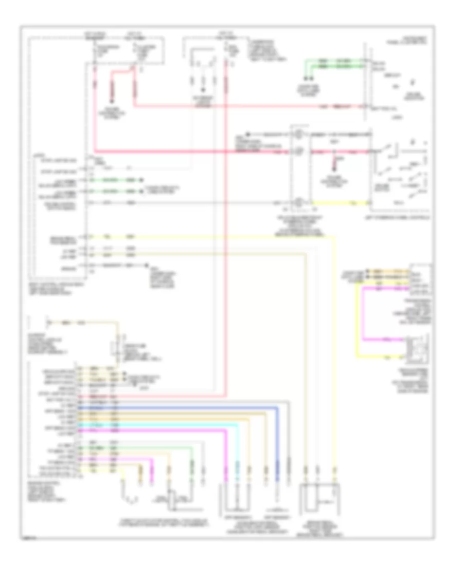
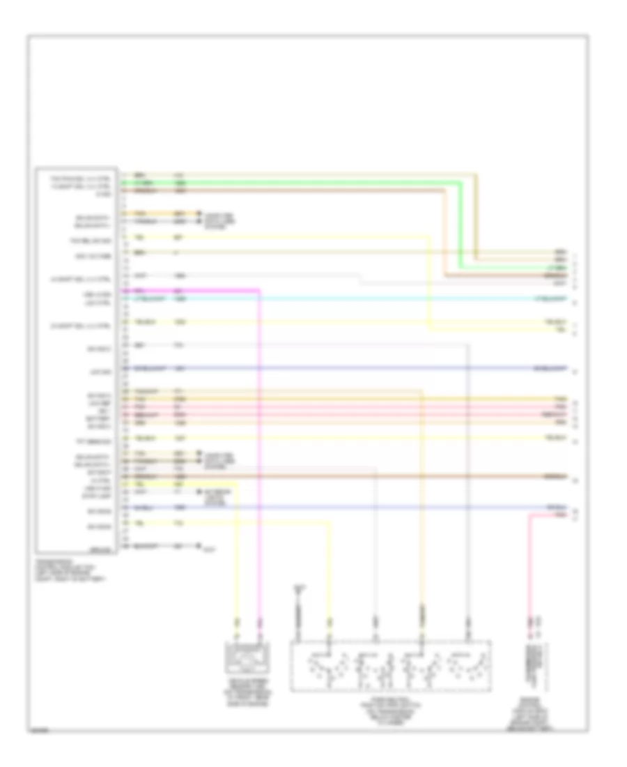
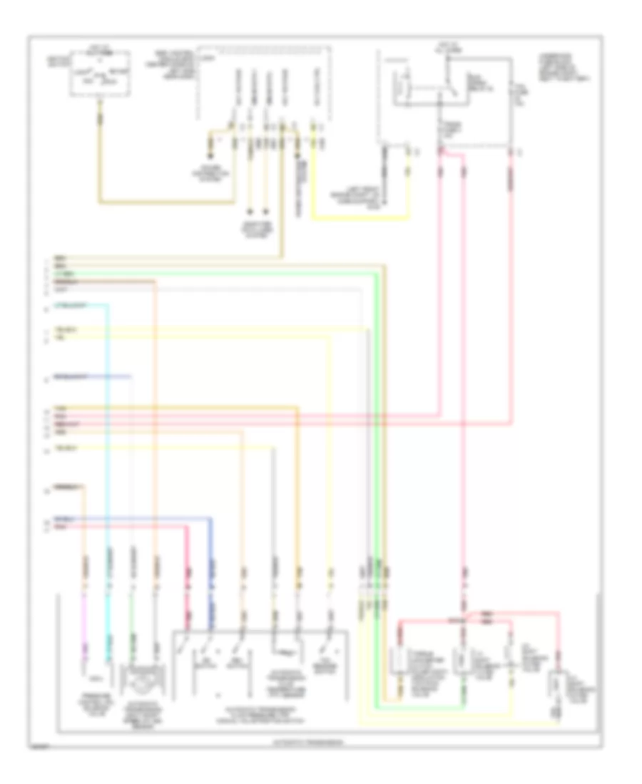
3.5L VIN N, Manual A/C Wiring Diagram (1 of 2) for Saturn Aura XR 2007
List of elements for 3.5L VIN N, Manual A/C Wiring Diagram (1 of 2) for Saturn Aura XR 2007:
- (not used)
- 5 volt ref
- A/c clu fuse 1 10a
- A/c clutch relay
- A/c compressor clutch (lower left, front of engine, part of a/c compressor)
- A/c req sig
- A/c request ind
- A/c request switch
- A10
- A11
- A11 c2
- A12
- A2 c1
- Air temp dr pos sig
- Ambient air temperature sensor (left front impact bar, behind grille)
- B10
- B10 c2
- B11
- B12
- B9 c3
- Batt
- Blower motor resistor assembly
- Blower motor switch
- C1 e3
- Cool fan 1 fuse 17 30a
- Cool fan 2 fuse 18 30a
- Cool/ fan 1 relay
- Cool/ fan 2 relay
- Cool/fan ser/par relay
- Defog ind
- Defog switch
- Defogger system
- Dr ctrl a
- Dr ctrl b
- E1 c2
- E8 c1
- Fresh air ind
- Fresh air switch
- G106 (3.5l: rear of engine, above oil filter)
- G201 (under dash, right side of console, near floor)
- Ground
- Hot at all times
- Hot in run or start
- Hvac control module
- Ign 3 vol
- Interior lights system
- Left cooling fan (left rear of radiator)
- Logic
- Low ref
- Mode dr pos sig
- Mode switch
- Recirculation ind
- Recirculation switch
- Right cooling fan (right rear of radiator)
- Tan
- Temperature control switch
- Underhood fuse block (left side of engine compt, next to battery)
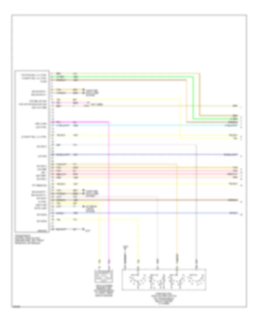
3.5L VIN N, Manual A/C Wiring Diagram (2 of 2) for Saturn Aura XR 2007
List of elements for 3.5L VIN N, Manual A/C Wiring Diagram (2 of 2) for Saturn Aura XR 2007:
- 3.5l
- 3.5l 3.6l
- 3.6l
- 5v ref
- A/c refrigerant pressure sensor (on a/c line)
- A/c req sig
- After blow
- Air temperature actuator (center of hvac unit)
- Ambient air temp sens sig
- Blower motor (right side of hvac unit)
- Body control module (bcm) (center console, left side near dash)
- Clu rly ctrl
- Computer data lines system
- Data link connector (dlc) (lower left of dash)
- E3 c4
- Ect sens sig
- Engine control module (ecm) (left side of engine compt, front of battery)
- Engine coolant temperature (ect) sensor (3.5l: in cylinder head, below coolant reservoir) (3.6l: left side of engine, behind generator)
- G203 (under dash, right side of console, near floor)
- Ground
- High spd gmlan
- High spd rly ctrl
- High speed gmlan serial data +
- High speed gmlan serial data -
- Hot at all times
- Hvac blower fuse 20a
- Hvac blower high relay
- Hvac ctrl (batt) fuse 10a
- Hvac ctrl (ign) fuse 10a
- Logic
- Low ref
- Low spd rly ctrl
- Low speed gmlan serial data
- Mode actuator (on left of hvac unit)
- Recirculation actuator (top right of hvac unit)
- Run relay
- Run rly ctrl
- Sens sig
- Tan
3.6L VIN 7
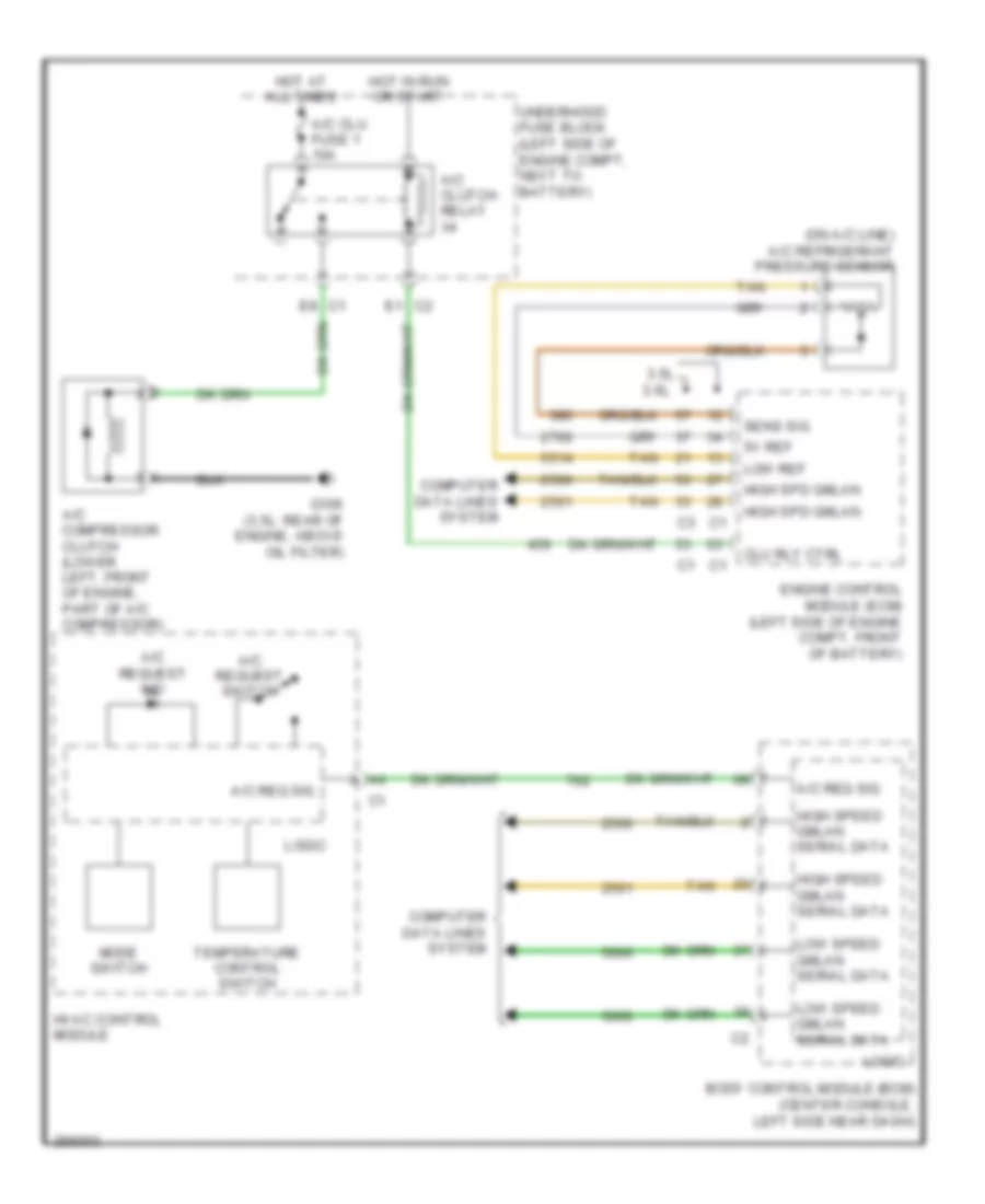
3.6L VIN 7, Compressor Wiring Diagram, with Auto A/C for Saturn Aura XR 2007
List of elements for 3.6L VIN 7, Compressor Wiring Diagram, with Auto A/C for Saturn Aura XR 2007:
- (on a/c line) a/c refrigerant pressure sensor
- 5v ref
- A/c clu fuse 1 10a
- A/c clutch relay
- A/c compressor clutch (lower left front of engine, part of a/c compressor)
- Body control module (bcm) (center console, left side near dash)
- C1 e8
- C2 e1
- Clu rly ctrl
- Computer data lines system
- Engine control module (ecm) (2.4l: left side of engine compt, behind battery) (3.6l: left side of engine compt, front of battery)
- G106 (2.4l: rear of engine, near pnp switch)
- High spd gmlan
- High speed gmlan serial data
- Hot at all times
- Hot in run or start
- Hvac control module
- Logic
- Low ref
- Low speed gmlan serial data
- Lower air
- Mode switch
- Sens sig
- Serial data
- Switch temperature upper air
- Tan
- Temperature switch
- Underhood fuse block (left side of engine compt, next to battery)
3.6L VIN 7, Compressor Wiring Diagram, with Manual A/C for Saturn Aura XR 2007
List of elements for 3.6L VIN 7, Compressor Wiring Diagram, with Manual A/C for Saturn Aura XR 2007:
- (on a/c line) a/c refrigerant pressure sensor
- 3.5l 3.6l
- 5v ref
- A/c clu fuse 1 10a
- A/c clutch relay
- A/c compressor clutch (lower left, front of engine, part of a/c compressor)
- A/c req sig
- A/c request ind
- A/c request switch
- Body control module (bcm) (center console, left side near dash)
- Clu rly ctrl
- Computer data lines system
- E1 c2
- E8 c1
- Engine control module (ecm) (left side of engine compt, front of battery)
- G106 (3.5l: rear of engine, above oil filter)
- High spd gmlan
- High speed gmlan serial data
- Hot at all times
- Hot in run or start
- Hvac control module
- Logic
- Low ref
- Low speed gmlan serial data
- Mode switch
- Sens sig
- Tan
- Temperature control switch
- Underhood fuse block (left side of engine compt, next to battery)
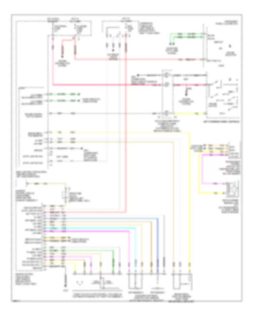
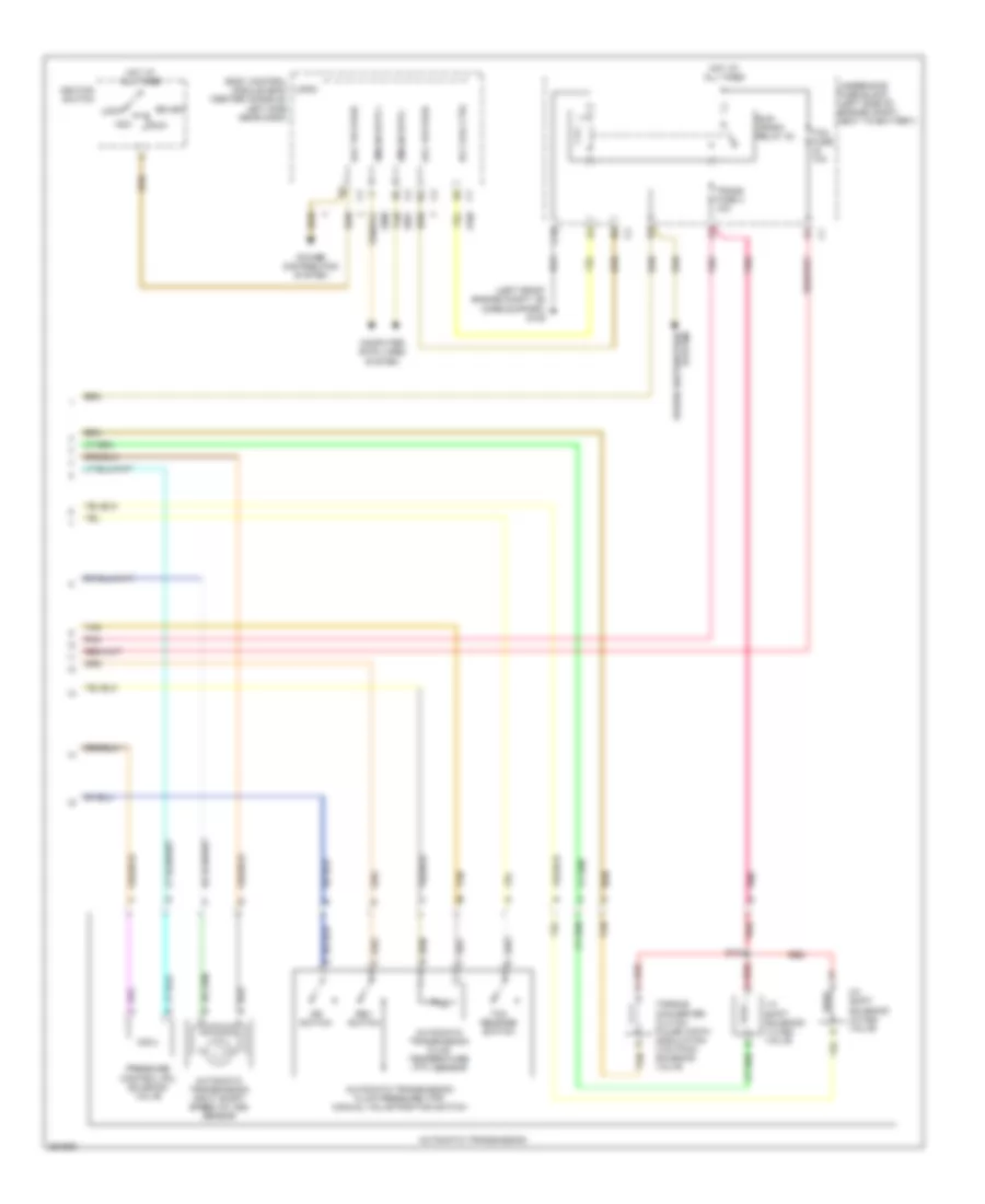
3.6L VIN 7, Manual A/C Wiring Diagram (1 of 2) for Saturn Aura XR 2007
List of elements for 3.6L VIN 7, Manual A/C Wiring Diagram (1 of 2) for Saturn Aura XR 2007:
- (not used)
- 5 volt ref
- A/c clu fuse 1 10a
- A/c clutch relay
- A/c compressor clutch (lower left, front of engine, part of a/c compressor)
- A/c req sig
- A/c request ind
- A/c request switch
- A10
- A11
- A11 c2
- A12
- A2 c1
- Air temp dr pos sig
- Ambient air temperature sensor (left front impact bar, behind grille)
- B10
- B10 c2
- B11
- B12
- B9 c3
- Batt
- Blower motor resistor assembly
- Blower motor switch
- C1 e3
- Cool fan 1 fuse 17 30a
- Cool fan 2 fuse 18 30a
- Cool/ fan 1 relay
- Cool/ fan 2 relay
- Cool/fan ser/par relay
- Defog ind
- Defog switch
- Defogger system
- Dr ctrl a
- Dr ctrl b
- E1 c2
- E8 c1
- Fresh air ind
- Fresh air switch
- G106 (3.5l: rear of engine, above oil filter)
- G201 (under dash, right side of console, near floor)
- Ground
- Hot at all times
- Hot in run or start
- Hvac control module
- Ign 3 vol
- Interior lights system
- Left cooling fan (left rear of radiator)
- Logic
- Low ref
- Mode dr pos sig
- Mode switch
- Recirculation ind
- Recirculation switch
- Right cooling fan (right rear of radiator)
- Tan
- Temperature control switch
- Underhood fuse block (left side of engine compt, next to battery)
3.6L VIN 7, Manual A/C Wiring Diagram (2 of 2) for Saturn Aura XR 2007
List of elements for 3.6L VIN 7, Manual A/C Wiring Diagram (2 of 2) for Saturn Aura XR 2007:
- 3.5l
- 3.5l 3.6l
- 3.6l
- 5v ref
- A/c refrigerant pressure sensor (on a/c line)
- A/c req sig
- After blow
- Air temperature actuator (center of hvac unit)
- Ambient air temp sens sig
- Blower motor (right side of hvac unit)
- Body control module (bcm) (center console, left side near dash)
- Clu rly ctrl
- Computer data lines system
- Data link connector (dlc) (lower left of dash)
- E3 c4
- Ect sens sig
- Engine control module (ecm) (left side of engine compt, front of battery)
- Engine coolant temperature (ect) sensor (3.5l: in cylinder head, below coolant reservoir) (3.6l: left side of engine, behind generator)
- G203 (under dash, right side of console, near floor)
- Ground
- High spd gmlan
- High spd rly ctrl
- High speed gmlan serial data +
- High speed gmlan serial data -
- Hot at all times
- Hvac blower fuse 20a
- Hvac blower high relay
- Hvac ctrl (batt) fuse 10a
- Hvac ctrl (ign) fuse 10a
- Logic
- Low ref
- Low spd rly ctrl
- Low speed gmlan serial data
- Mode actuator (on left of hvac unit)
- Recirculation actuator (top right of hvac unit)
- Run relay
- Run rly ctrl
- Sens sig
- Tan
ANTI-LOCK BRAKES
Anti-lock Brakes Wiring Diagram (1 of 2) for Saturn Aura XR 2007
List of elements for Anti-lock Brakes Wiring Diagram (1 of 2) for Saturn Aura XR 2007:
- 5v ref
- A10
- A11
- A12
- A13
- A14
- Abs fuse 15 10a
- Abs fuse 24 60a
- B10
- B11
- B12
- B13
- B14
- Bat
- Body control module (bcm) (center console, left side near dash)
- Brake fluid pressure sensor (left side engine compartment, on ebcm)
- Brake fluid pressure sig
- Brake pressure modulator valve (bpmv)
- C10
- C11
- C12
- C13
- C14
- Cluster theft fuse 10a
- Computer data lines system
- Electronic brake control module (ebcm) (left rear engine compartment, next to strut tower)
- G109 (left front engine compartment, on core support)
- Gmlan serial data (+)
- Gmlan serial data (-)
- Gnd
- Hot at all times
- Hot w/ run/ crank relay energized
- Ign 1 voltage
- Lateral accelerometer sig
- Left front wheel speed sensor (wss) (left front wheel hub)
- Left rear wheel speed sensor (wss) (left rear wheel hub)
- Lf outlet solenoid valve
- Lf wheel sens sply voltage
- Lf wheel spd sens sig
- Low ref
- Low reference
- Lr outlet solenoid valve
- Lr wheel sens sply voltage
- Lr wheel spd sens sig
- Pnk
- Power distribution system
- Pump motor
- Pump motor control
- Rf outlet solenoid valve
- Rf wheel sens sply voltage
- Rf wheel spd sens sig
- Right front wheel speed sensor (wss) (right front wheel hub)
- Right rear wheel speed sensor (right rear wheel hub)
- Rr inlet solenoid valve
- Rr outlet solenoid valve
- Rr wheel sens sply voltage
- Rr wheel spd sens sig
- Solenoid valve control
- Solenoid valve lf inlet
- Solenoid valve lr inlet
- Solenoid valve rf inlet
- Strng wheel pos sig a
- Strng wheel pos sig b
- Tan
- Underhood fuse block (left side of engine compartment, next to battery)
- W/ automatic electronic controlled ride & handling
- Yaw rate sens sig
Anti-lock Brakes Wiring Diagram (2 of 2) for Saturn Aura XR 2007
List of elements for Anti-lock Brakes Wiring Diagram (2 of 2) for Saturn Aura XR 2007:
- (2.4l) brake booster vacuum sensor
- (behind right front kick panel) g305
- (left front engine compartment, on core support) g109
- (left side engine compartment, on ebcm) (2.4l) brake fluid pressure sensor
- 2.4l/3.6l
- 3.5l
- 5v ref
- Abs ind
- Battery pos volt
- Body control module (bcm) (center console, left side near dash)
- Brake booster vacuum sensor signal
- Brake fluid
- Brake fluid level switch (under center brake fluid reservoir)
- Brake fluid pressure sensor signal
- Brake ind
- Brake pedal position sensor (right side brake pedal bracket)
- Brk pos sens sig
- Computer data lines system
- Data serial
- Ebcm
- Engine control module (ecm) (2.4l: left side of engine compartment, behind battery) (3.5l/3.6l: left side of engine compartment, front of battery)
- G201 (under dash, right side of console, near floor)
- Gmlan
- Gmlan serial data bus (+)
- Gmlan serial data bus (-)
- Ground
- High speed
- Ign
- Instrument panel cluster (ipc)
- Interior lights system
- Lat accel sig
- Level sensor
- Logic
- Low ref
- Low reference
- Low speed
- Low speed gmlan
- Pnk
- Sens sig yaw rate
- Serial data
- Serial data gmlan
- Signal
- Steering wheel position sensor (under dash, at base of steering column)
- Strng wheel pos sig a
- Strng wheel pos sig b
- Sw sig
- Tan
- Trac ctrl
- Traction control ind
- Traction control switch
- Traction off ind
- Yaw rate & lateral acceleration sensor (2.4l) (under center console)
ANTI-THEFT
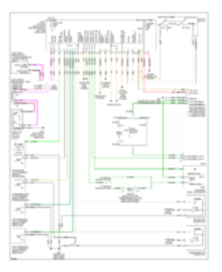
Anti-theft Wiring Diagram for Saturn Aura XR 2007
List of elements for Anti-theft Wiring Diagram for Saturn Aura XR 2007:
- (left front engine compt) starter generator control module (sgcm)
- (left side of engine compt, next to battery) underhood fuse block
- 5v ref
- Acc
- Acc run
- Acc volt
- Ajar
- Ajar sw sig rr compt lid
- Ajar switch signal
- Automatic a/c
- B10
- Batt
- Battery
- Body control module (bcm) (center console, left side near dash)
- Closed
- Cluster/ theft fuse 10a
- Cntrl
- Computer data lines system
- Crank volt off/run/
- Door lock
- Door lock fuse 15a
- Driver door latch assembly (rear of driver door)
- Driver door lock switch
- Exterior lights system
- G101 (left side of engine compt, near g109)
- G201 (under dash, right side of console, near floor)
- G301 (behind top right rear seat back)
- Ground
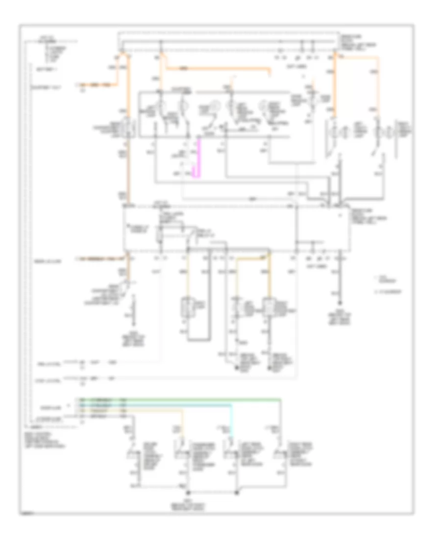
- Headlights system
- Headlp high beam rly
- Hood ajar sw sig c1
- Hood ajar switch (on hood latch)
- Hood closed sw sig
- Horn relay control
- Horns system
- Hot at all times
- Hvac control module
- Ignition switch
- Instrument panel cluster (ipc)
- Interior lights system
- Key sw sig drv dr
- Left rear door latch assembly (rear of left rear door)
- Lock
- Logic
- Low spd serial
- Low spd serial data
- Manual a/c
- Off
- Park lp relay cntrl
- Passenger door latch assembly (rear of front passenger door)
- Passenger door lock switch
- Power distribution system
- Radio
- Right rear door latch assembly (rear of right rear door)
- Run
- Security ind
- Serial data
- Signal lck/unlck
- Start
- Sw sig
- Tan
- Theft deterrent control module (left side of dash, on ignition key cylinder housing)
- Trunk, tailgate, fuel doors system
- Unlock
- Vehicle communications interface module (vcim) (right side of dash, above kick panel)
- W/ hybrid system
- W/ vehicle communications
- W/o hybrid system
- W/o vehicle communications
BODY CONTROL MODULES
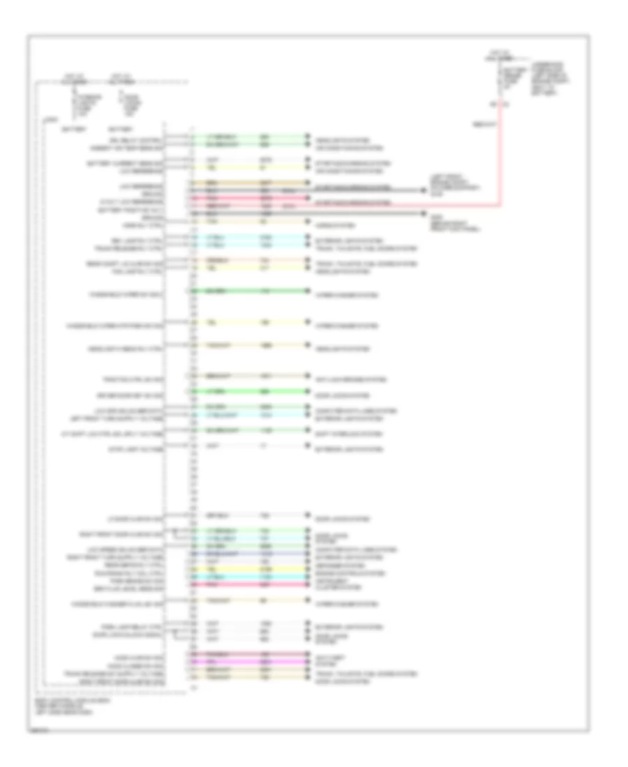
Body Control Modules Wiring Diagram (1 of 4) for Saturn Aura XR 2007
List of elements for Body Control Modules Wiring Diagram (1 of 4) for Saturn Aura XR 2007:
- (2.4l)
- (left front engine compt, on core support) g109
- 5-volt low reference
- A/t shift lck ctrl sol sply voltage
- Air conditioning system
- Ambient air temp sens sig
- Anti-lock brakes system
- Anti-theft system
- B3 c2
- Battery
- Battery current sens sig
- Battery positive volt
- Battery sense fuse 5a
- Body control module (bcm) (center console, left side near dash)
- Brk fluid level sens sig
- Computer data lines system
- Defogger system
- Door lock/unlock signal
- Door locks fuse 15a
- Door locks system
- Driver door key sw sig
- Drl relay control
- Engine controls system
- Exterior lights system
- Fog lamp rly ctrl
- G305 (behind right front kick panel)
- Ground
- Headlamp hi beam rly ctrl
- Headlights system
- Hood ajar sw sig
- Hood closed sw sig
- Horn rly ctrl
- Horns system
- Hot at all times
- Instrument cluster system
- Interior lights fuse 10a
- Lf door ajar sw sig
- Logic
- Low reference
- Low spd gmlan ser data
- Low speed gmlan ser data
- Park brake sw sig
- Park lamp relay ctrl
- Pnk
- Rear compt lid ajar sw sig
- Rear defog rly ctrl
- Rev lamp rly ctrl
- Right front door ajar sw sig
- Run/crank rly coil ctrl
- Shift interlock system
- Starting/charging system
- Stop lamp voltage
- Tan
- Traction ctrl sw sig
- Trunk release rly ctrl
- Trunk, tailgate, fuel doors system
- Underhood fuse block (left side of engine compt, next to battery)
- Windshield washer fluid lev sig
- Windshield wiper mtr park sw sig
- Windshield wiper sw sig 2
- Wiper/washer system
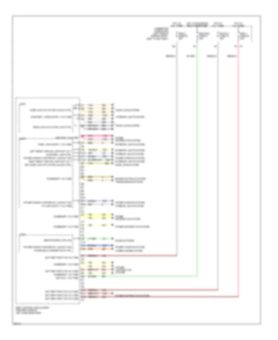
Body Control Modules Wiring Diagram (2 of 4) for Saturn Aura XR 2007
List of elements for Body Control Modules Wiring Diagram (2 of 4) for Saturn Aura XR 2007:
- A10
- A11
- A12
- Accessory voltage
- B10
- B11
- B12
- Battery positive voltage
- Body control module (bcm) (center console, left side near dash)
- C10
- C11
- C12
- Courtesy lamp ctrl
- D10
- D11
- D12
- Door lock actuator lock ctrl
- Door lock actuator unlock ctrl
- Door locks system
- Drv door lock actuator unlock ctrl
- Engine controls system
- Exterior lights system
- Hot at all times
- Hot w/ run/crank relay energized
- Ibcm (r/c) fuse 21 30a
- Ibcm 1 fuse 20 30a
- Ibcm 2 fuse 25 50a
- Ignition 1 voltage
- Interior lights system
- Left rear turn sig lamp sup volt
- Logic
- Pnk
- Power distribution system
- Power window master sw lockout sig
- Power windows system
- Remote radio ctrl sig
- Right rear turn sig lamp sup volt
- Run rly fuse 19 30a
- Sound systems
- Tan
- Transmissions system
- Underhood fuse block (left side of engine compt, next to battery)
- Windshield washer pump ctrl
- Wiper/washer system
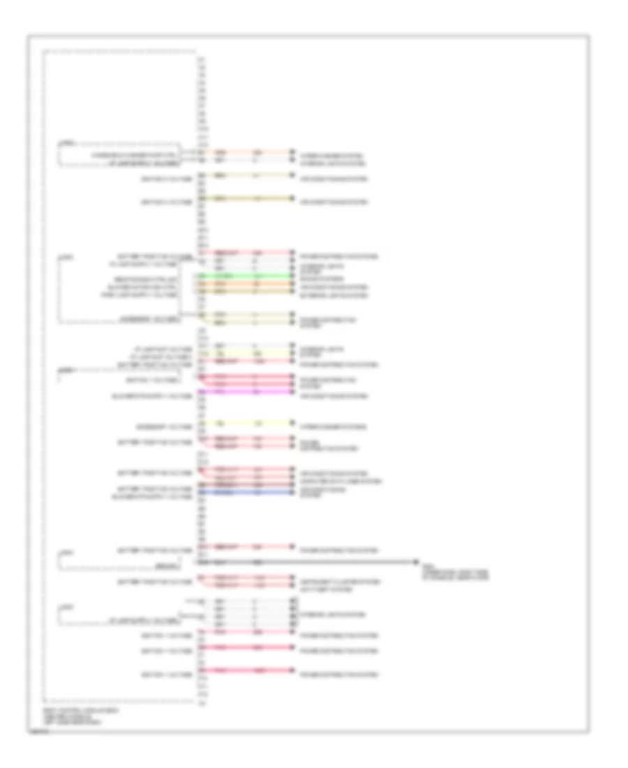
Body Control Modules Wiring Diagram (3 of 4) for Saturn Aura XR 2007
List of elements for Body Control Modules Wiring Diagram (3 of 4) for Saturn Aura XR 2007:
- A10
- A11
- A12
- Accessory voltage
- Air conditioning system
- Anti-theft system
- B10
- B11
- B12
- Battery positive voltage
- Blower motor high ctrl
- Body control module (bcm) (center console, left side near dash)
- C10
- C11
- C12
- Computer data lines system
- D10
- D11
- D12
- E10
- E11
- E12
- Exterior lights system
- F10
- F11
- F12
- G203 (under dash, right side of console, near floor)
- Ground
- I/p lamp sup voltage
- I/p lamp sup voltage 3
- Ignition 1 voltage
- Ignition 3 voltage
- Instrument cluster system
- Interior lights system
- Logic
- Pnk
- Power distribution system
- Remote radio ctrl sig
- Sound systems
- Windshield washer pump ctrl
- Wiper/washer system
- Wiper/washer systems
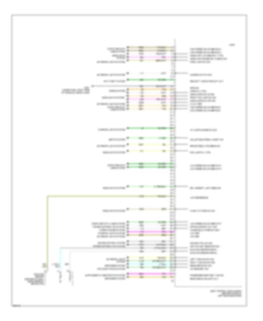
Body Control Modules Wiring Diagram (4 of 4) for Saturn Aura XR 2007
List of elements for Body Control Modules Wiring Diagram (4 of 4) for Saturn Aura XR 2007:
- 5 volt ref
- A/c request sig
- Adjustable pedal inhibit sw
- Air conditioning system
- Anti-theft system
- Body control module (bcm) (center console, left side near dash)
- Brake pedal pos sens sig
- Computer data lines system
- Cruise control system
- Cruise ctrl sw sig
- Defogger system
- Drl ambient light sens sig
- Exterior lights system
- Flash to pass sw sig
- Fog lamp rly ctrl
- Front fog lamp sw sig
- G201 (under dash, right side of console, near floor)
- Ground
- Hazard switch sig
- Headlamp dimmer sw hi beam sig
- Headlamp low beam rly ctrl
- Headlamps sw off sig
- Headlamps sw on sig
- Headlights system
- High speed gmlan ser bus +
- High speed gmlan ser bus -
- Horn rly ctrl
- Horns system
- I/p lamps dimmer sw sig
- Ignition key resistor sig
- Interior lights system
- Left turn sig sw sig
- Logic
- Low ref
- Low reference
- Low speed gmlan ser data
- Off/run/crank volt sig
- Park lamp sw sig
- Passenger seat belt ind sig
- Power distribution system
- Rear defog ind sup volt
- Rear defog sw sig
- Right turn sig sw sig
- Seats system
- Security indicator sup volt
- Sunload sensor (center of dash, near defrost deflector)
- Sunload sensor signal
- Tan
- Windshield wiper sw sig 1
- Wiper/washer system
COMPUTER DATA LINES
2.4L VIN 5
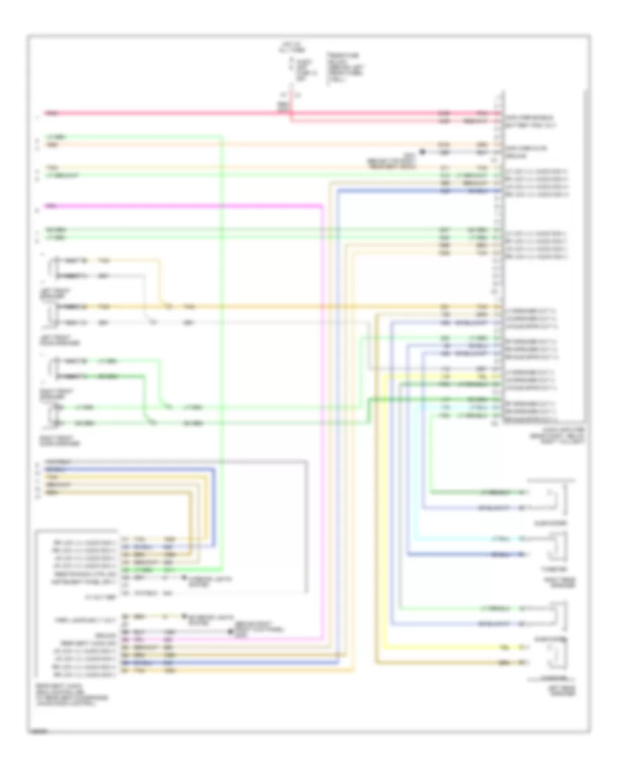
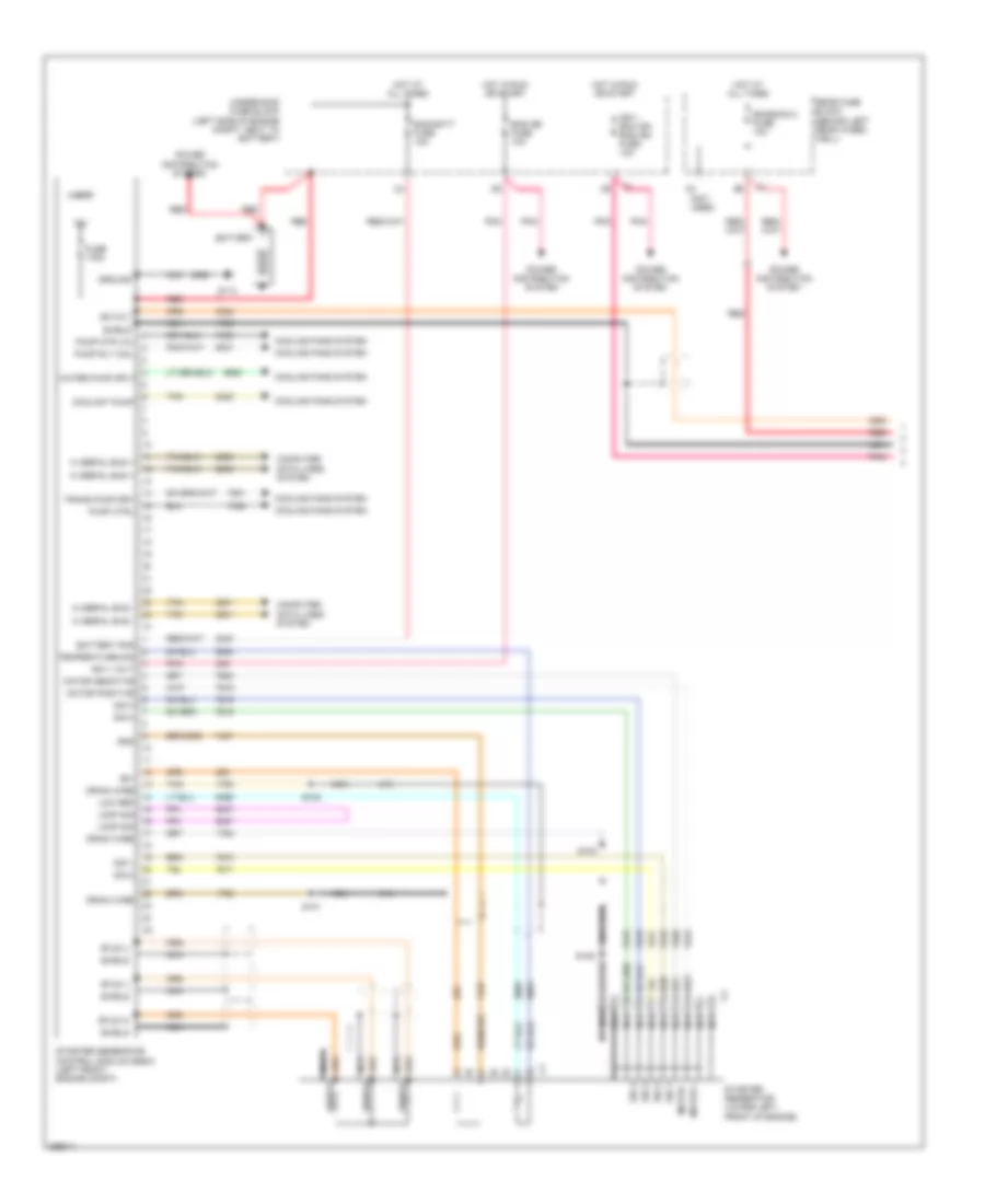
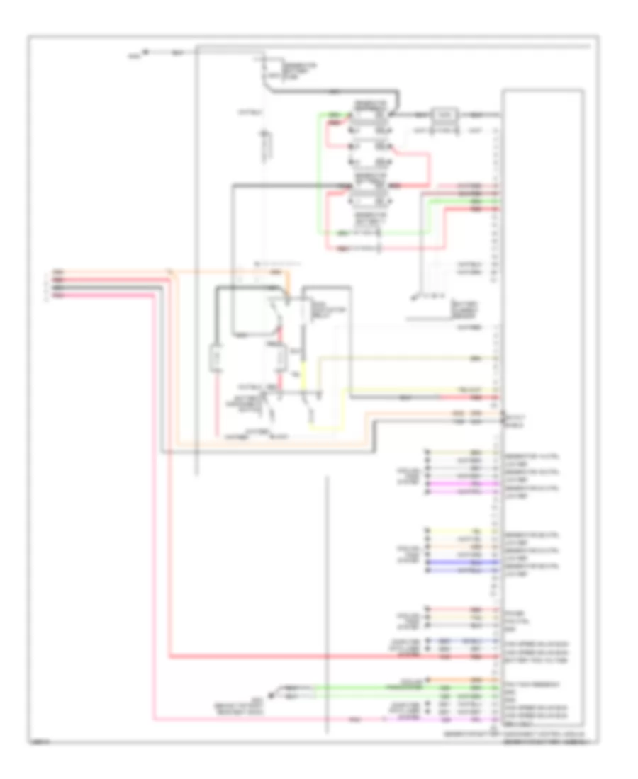
2.4L VIN 5, Computer Data Lines Wiring Diagram for Saturn Aura XR 2007
List of elements for 2.4L VIN 5, Computer Data Lines Wiring Diagram for Saturn Aura XR 2007:
- (left side of engine compt, behind battery) engine control module (ecm)
- Automatic a/c
- B10
- B11
- B12
- Body control module (bcm) (center console, left side near dash)
- Data link connector (dlc) (lower left of dash)
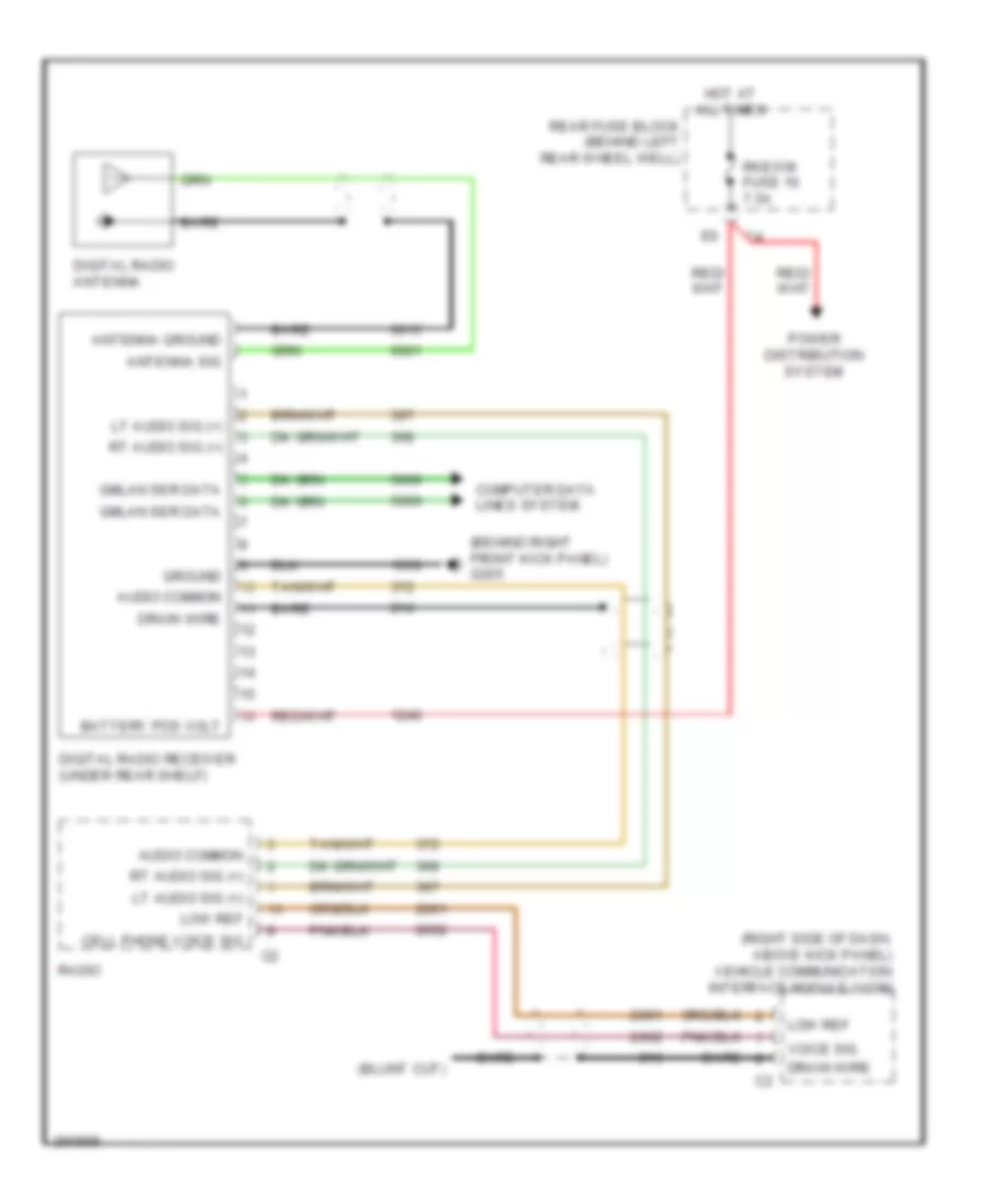
- Digital radio receiver (under rear shelf)
- Electronic brake control module (ebcm) (left rear engine compt, next to strut tower)
- G201 (under dash, right side of console, near floor)
- G203 (under dash, right side of console, near floor)
- Generator disconnect control module (behind right rear seat)
- Gmlan data bus +
- Gmlan data bus -
- High speed gmlan serial data bus +
- High speed gmlan serial data bus -
- Hot at all times
- Hs gmlan data bus +
- Hs gmlan data bus -
- Hvac control module
- Hvac ctrl (batt) fuse 10a
- Inflatable restraint sensing & diagnostic module (sdm) (under center console)
- Instrument panel cluster (ipc)
- Logic
- Low speed gmlan serial data
- Ls gmlan data
- Manual a/c
- Power distribution system
- Power steering control module (under dash, left of steering column)
- Radio
- Remote control door lock receiver (rcdlr) (center of rear window shelf)
- Starter generator control module (sgcm) (left front engine compt)
- Tan
- Theft deterrent control module (left side of dash, on ignition key cylinder housing)
- Transmission control module (tcm) (left side of engine compt, right of battery)
- Vehicle communications interface module (vcim) (right side of dash, above kick panel)
- W/ digital radio
- W/ onstar
- W/o digital radio
- W/o onstar
3.5L VIN N
3.5L VIN N, Computer Data Lines Wiring Diagram for Saturn Aura XR 2007
List of elements for 3.5L VIN N, Computer Data Lines Wiring Diagram for Saturn Aura XR 2007:
- (left side of engine compt, front of battery) engine control module (ecm)
- 3.5l
- 3.6l
- A/t 4 speed
- A/t 6 speed
- Automatic a/c
- B10
- B11
- B12
- Body control module (bcm) (center console, left side near dash)
- Data link connector (dlc) (lower left of dash)
- Digital radio receiver (under rear shelf)
- Electronic brake control module (ebcm) (left rear engine compt, next to strut tower)
- G201 (under dash, right side of console, near floor)
- G203 (under dash, right side of console, near floor)
- Gmlan data bus +
- Gmlan data bus -
- High speed gmlan serial data bus +
- High speed gmlan serial data bus -
- Hot at all times
- Hs gmlan data bus +
- Hs gmlan data bus -
- Hvac control module
- Hvac ctrl (batt) fuse 10a
- Inflatable restraint sensing & diagnostic module (sdm) (under center console)
- Instrument panel cluster (ipc)
- Logic
- Low speed gmlan serial data
- Ls gmlan data
- Manual a/c
- Power distribution system
- Power steering control module (under dash, left of steering column)
- Radio
- Remote control door lock receiver (rcdlr) (center of rear window shelf)
- Tan
- Theft deterrent control module (left side of dash, on ignition key cylinder housing)
- Transmission control module (tcm) (inboard side, left front frame rail extension)
- Vehicle communications interface module (vcim) (right side of dash, above kick panel)
- W/ digital radio
- W/ onstar
- W/ power steering
- W/o digital radio
- W/o onstar
- W/o power steering
3.6L VIN 7
3.6L VIN 7, Computer Data Lines Wiring Diagram for Saturn Aura XR 2007
List of elements for 3.6L VIN 7, Computer Data Lines Wiring Diagram for Saturn Aura XR 2007:
- (left side of engine compt, front of battery) engine control module (ecm)
- 3.5l
- 3.6l
- A/t 4 speed
- A/t 6 speed
- Automatic a/c
- B10
- B11
- B12
- Body control module (bcm) (center console, left side near dash)
- Data link connector (dlc) (lower left of dash)
- Digital radio receiver (under rear shelf)
- Electronic brake control module (ebcm) (left rear engine compt, next to strut tower)
- G201 (under dash, right side of console, near floor)
- G203 (under dash, right side of console, near floor)
- Gmlan data bus +
- Gmlan data bus -
- High speed gmlan serial data bus +
- High speed gmlan serial data bus -
- Hot at all times
- Hs gmlan data bus +
- Hs gmlan data bus -
- Hvac control module
- Hvac ctrl (batt) fuse 10a
- Inflatable restraint sensing & diagnostic module (sdm) (under center console)
- Instrument panel cluster (ipc)
- Logic
- Low speed gmlan serial data
- Ls gmlan data
- Manual a/c
- Power distribution system
- Power steering control module (under dash, left of steering column)
- Radio
- Remote control door lock receiver (rcdlr) (center of rear window shelf)
- Tan
- Theft deterrent control module (left side of dash, on ignition key cylinder housing)
- Transmission control module (tcm) (inboard side, left front frame rail extension)
- Vehicle communications interface module (vcim) (right side of dash, above kick panel)
- W/ digital radio
- W/ onstar
- W/ power steering
- W/o digital radio
- W/o onstar
- W/o power steering
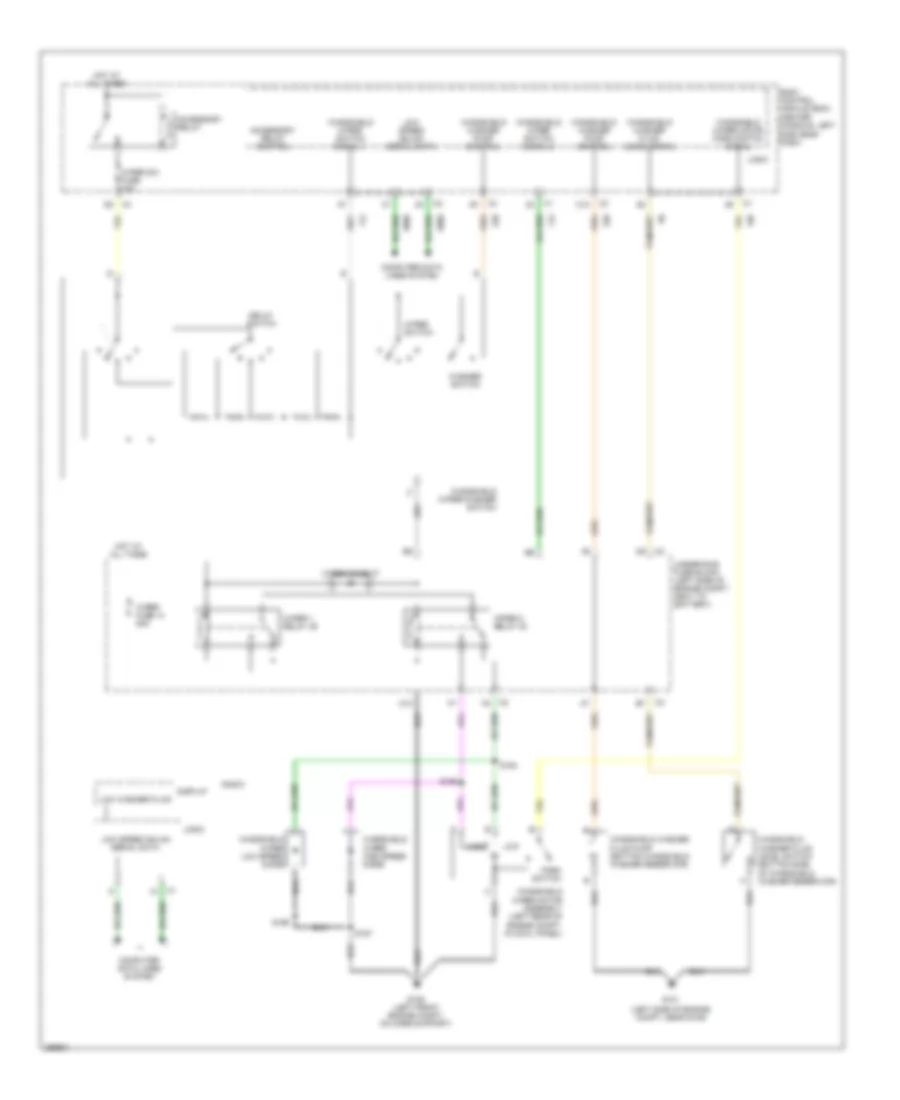
COOLING FAN
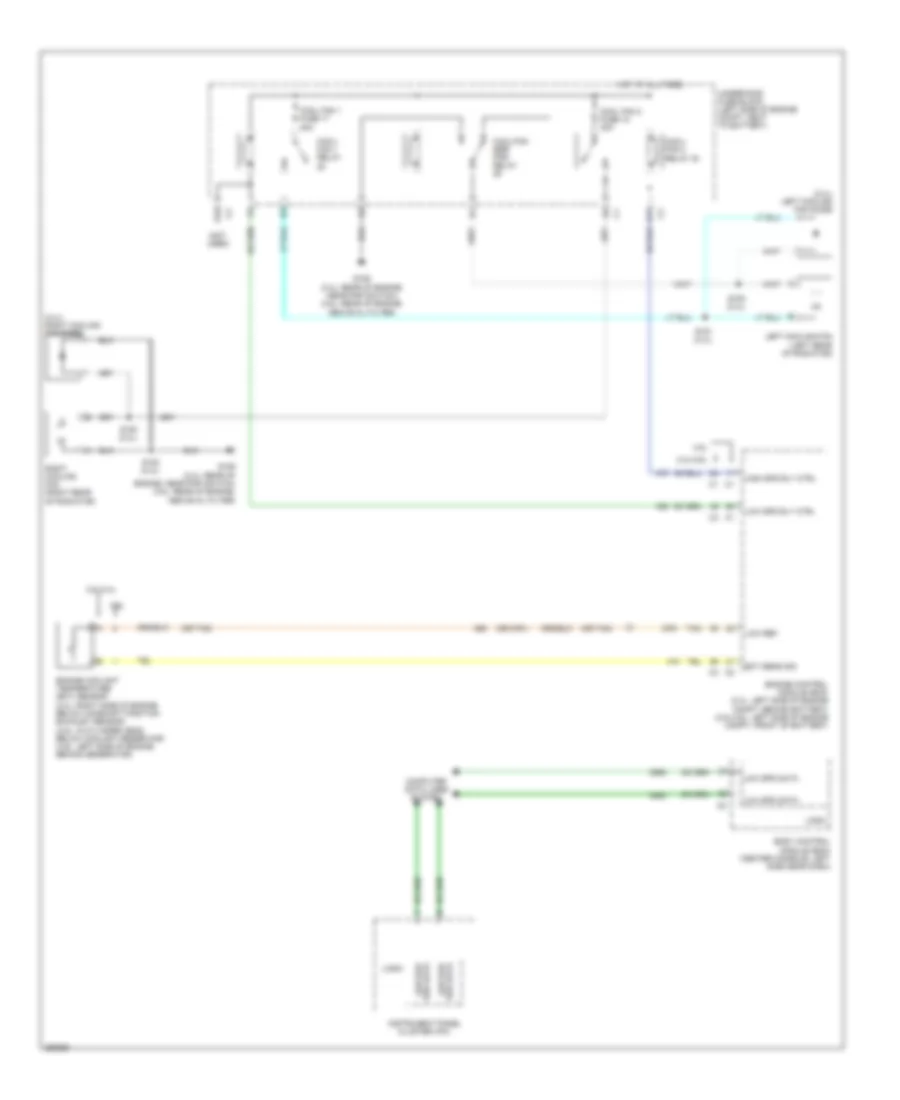
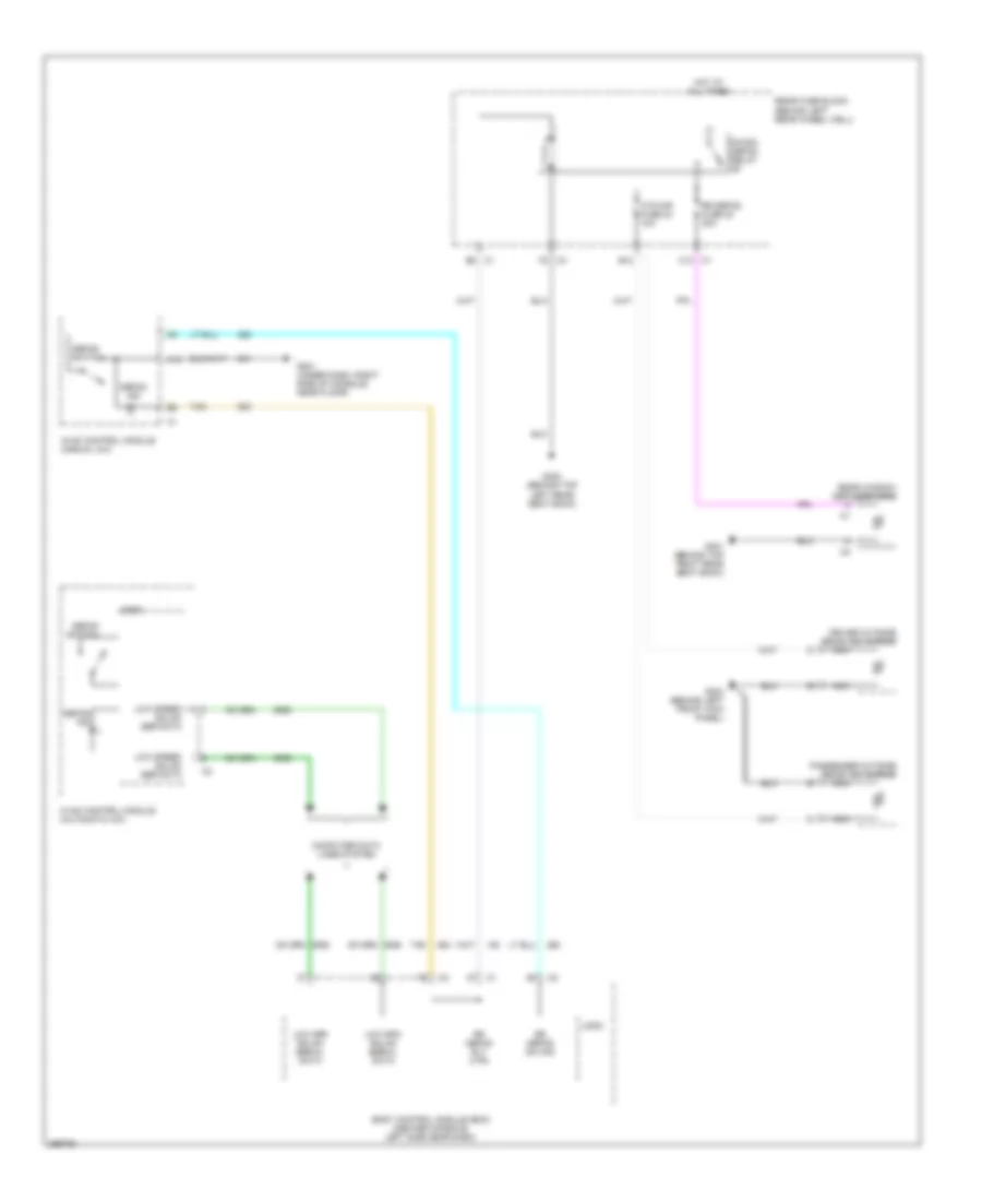
Cooling Fan Wiring Diagram, Except Hybrid for Saturn Aura XR 2007
List of elements for Cooling Fan Wiring Diagram, Except Hybrid for Saturn Aura XR 2007:
- (2.4l) left cooling fan diode
- (2.4l) right cooling fan diode
- (not used)
- (or 2761)
- (or tan)
- 2.4l/3.6l
- 3.5l
- 3.5l/2.4l
- 3.6l
- A11
- B10
- Body control module (bcm) (center console, left side near dash)
- Computer data lines system
- Cool fan 1 fuse 17 30a
- Cool fan 2 fuse 18 30a
- Cool/ fan 1 relay
- Cool/ fan 2 relay 30
- Cool/fan ser/ par relay
- Ect sens sig
- Engine control module (ecm) (2.4l: left side of engine compt, behind battery) (3.5l/3.6l: left side of engine compt, front of battery)
- Engine coolant temperature (ect) sensor (2.4l: right side of engine, below camshaft position exhaust sensor) (3.5l: in cylinder head, below coolant reservoir) (3.6l: left side of engine, behind generator)
- G106 (2.4l: rear of engine, near pnp switch) (3.5l: rear of engine, above oil filter)
- High spd rly ctrl
- Hot at all times
- Instrument panel cluster (ipc)
- Left cooling fan (left rear of radiator)
- Logic
- Low ref
- Low spd data
- Low spd rly ctrl
- Low spd ser data
- Right cooling fan (right rear of radiator)
- S150 (2.4l)
- S151 (2.4l)
- S152 (2.4l)
- S153 (2.4l)
- Ser data low spd
- Tan
- Underhood fuse block (left side of engine compt, next to battery)
Hybrid Cooling System Wiring Diagram, Hybrid for Saturn Aura XR 2007
List of elements for Hybrid Cooling System Wiring Diagram, Hybrid for Saturn Aura XR 2007:
- (behind top right rear seat back) g301
- (front center of generator battery) generator battery vent fan
- (lower left side of engine, near a/c compressor) starter generator control module (sgcm) cooling pump
- (middle rear of engine) heater coolant pump
- (right front of transmission, below sgcm) transmission pump
- A trans pump driver error
- A12
- B pump control
- B10
- Bare
- Bas pmp fuse 5 20a
- Battery positive vol
- C pump motor vol
- C12
- C2 interlock loop sig
- Computer data lines system
- Coolant pump control
- Driver error
- Emission 2 fuse 5 10a
- F trans pump low ref
- Fan control
- Fan tach feedback
- G trans pump high ref
- G107
- G114
- Gen batt temp sens 1a control
- Gen batt temp sens 1b control
- Gen batt temp sens 2a control
- Gen batt temp sens 2b control
- Gen batt temp sens 3a control
- Gen batt temp sens 3b control
- Generator battery 1
- Generator battery 2
- Generator battery 3
- Generator battery assembly
- Generator battery disconnect control module
- Generator battery temperature sensor 1a
- Generator battery temperature sensor 1b
- Generator battery temperature sensor 2a
- Generator battery temperature sensor 2b
- Generator battery temperature sensor 3a
- Generator battery temperature sensor 3b
- Ground
- H trans pump sw control
- High speed gmlan serial data +
- High speed gmlan serial data -
- High vol
- Hot at all times
- Hot in run or start
- Ign 1 ecm ign bas ign fuse 3 10a
- Ignition 1 vol
- Interlock loop sig
- Low ref
- Maf injectors bas pmps fuse 5 20a
- Motor vol
- Nca
- Pnk
- Power
- Power distribution system
- Pump
- Pump control
- Pump driver (left front of engine compt, behind sgcm)
- Rear fuse block (behind left rear wheel well)
- Red
- Starter generator control module (sgcm) (left front engine compt)
- Tan
- Trans pmp mtr relay
- Trans pump
- Trans pump rly coil control
- Underhood fuse block (left side of engine compt, next to battery)
CRUISE CONTROL
2.4L VIN 5
2.4L VIN 5, Cruise Control Wiring Diagram, Hybrid for Saturn Aura XR 2007
List of elements for 2.4L VIN 5, Cruise Control Wiring Diagram, Hybrid for Saturn Aura XR 2007:
- (not used)
- 5 vol ref 2
- 5v ref
- 5v ref 2
- Accelerator pedal position (app) sensor (accelerator pedal bracket)
- App sens 1 sig
- App sens 2 sig
- App sensor 1
- App sensor 2
- Bat pos vol
- Bat pos volt
- Body control module (bcm) (center console, left side near dash)
- Brake pedal pos sens sig
- Brake pedal position sensor (right side brake pedal bracket)
- Bus +
- Bus -
- Cluster/ theft fuse 10a
- Computer data lines system
- Cruise control switch signal
- Cruise indicator
- Cruise switch
- Ecm fuse 10a
- Engine control module (ecm) (left side of engine compt, behind battery)
- Exterior lights system
- G107
- G201 (under dash, right side of console, near floor)
- Gmlan
- Ground
- High sig
- Hot at all times
- Hot in run or start
- Ign
- Inflatable restraint steering wheel module coil (in steering column, behind steering wheel)
- Instrument panel cluster (ipc)
- Left steering wheel controls
- Logic
- Low ref
- Low sig
- Low speed gmlan serial data
- Pnk
- Pnk e
- Power distribution system
- Res +
- Run/crank fuse 2a
- S201
- S209 pnk
- Ser dat
- Ser data bus+
- Ser data bus-
- Set -
- Stop lamp sw sig
- Tac motor ctrl 1
- Tac motor ctrl 2
- Tan
- Throttle actuator control (tac) module (left side of engine, on throttle assembly)
- Tp sens 1 sig
- Tp sens 2 sig
- Transmission control module (tcm) (left side of engine compt, right of battery)
- Underhood fuse block (left side of engine compt, next to battery)
- Vehicle speed sensor (vss) (a/t) (on transmission, at front, rear side of engine)
3.5L VIN N
3.5L VIN N, Cruise Control Wiring Diagram for Saturn Aura XR 2007
List of elements for 3.5L VIN N, Cruise Control Wiring Diagram for Saturn Aura XR 2007:
- (not used)
- 5v ref
- 5v ref 2
- Accelerator pedal position (app) sensor (accelerator pedal bracket)
- App sens 1 sig
- App sens 2 sig
- App sensor 1
- App sensor 2
- Bat pos vol
- Bat pos volt
- Body control module (bcm) (center console, left side near dash)
- Brake pedal pos sens sig
- Brake pedal position sensor (right side brake pedal bracket)
- Bus +
- Bus -
- Cluster/ theft fuse 10a
- Computer data lines system
- Cruise control switch signal
- Cruise indicator
- Cruise switch
- Ecm fuse 10a
- Engine control module (ecm) (left side of engine compt, front of battery)
- Exterior lights system
- G107
- G201 (under dash, right side of console, near floor)
- Gmlan
- Ground
- High sig
- Hot at all times
- Hot in run or start
- Ign
- Inflatable restraint steering wheel module coil (in steering column, behind steering wheel)
- Instrument panel cluster (ipc)
- Left steering wheel controls
- Logic
- Low ref
- Low sig
- Low speed gmlan serial data
- Pnk
- Pnk e
- Power distribution system
- Rear fuse block (behind left rear wheel well) c1
- Res +
- Run/crank fuse 2a
- S201
- S209 pnk
- Ser dat
- Ser data bus+
- Ser data bus-
- Set -
- Stop lamp sw sig
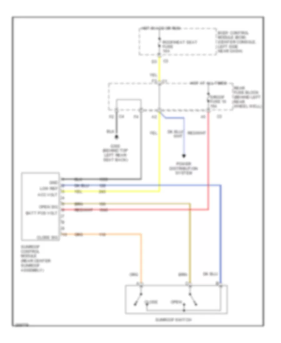
- Sunroof control module (if equipped) (rear center sunroof assembly)
- Tac motor ctrl 1
- Tac motor ctrl 2
- Tan
- Throttle actuator control (tac) module (top rear of engine, on throttle assembly)
- Tp sens 1 sig
- Tp sens 2 sig
- Tps1
- Tps2
- Transmission control module (tcm) (inboard side, left front frame rail extension)
- Underhood fuse block (left side of engine compt, next to battery)
- Vehicle spd sig
- Vehicle speed sensor (vss) (a/t) (on transmission, at front, rear side of engine)
3.6L VIN 7
3.6L VIN 7, Cruise Control Wiring Diagram for Saturn Aura XR 2007
List of elements for 3.6L VIN 7, Cruise Control Wiring Diagram for Saturn Aura XR 2007:
- (not used)
- 5v ref
- 5v ref 2
- Accelerator pedal position (app) sensor (accelerator pedal bracket)
- App sens 1 sig
- App sens 2 sig
- App sensor 1
- App sensor 2
- Bat pos vol
- Bat pos volt
- Body control module (bcm) (center console, left side near dash)
- Brake pedal pos sens sig
- Brake pedal position sensor (right side brake pedal bracket)
- Bus +
- Bus -
- Cluster/ theft fuse 10a
- Computer data lines system
- Cruise control switch signal
- Cruise indicator
- Cruise switch
- Ecm fuse 10a
- Engine control module (ecm) (left side of engine compt, front of battery)
- Exterior lights system
- G107
- G201 (under dash, right side of console, near floor)
- Gmlan
- Ground
- High sig
- Hot at all times
- Hot in run or start
- Ign
- Inflatable restraint steering wheel module coil (in steering column, behind steering wheel)
- Instrument panel cluster (ipc)
- Left steering wheel controls left steering wheel controls
- Logic
- Low ref
- Low sig
- Low speed gmlan serial data
- Pnk
- Pnk e
- Power distribution system
- Rear fuse block (behind left rear wheel well) c1
- Res +
- Run/crank fuse 2a
- S201
- S209 pnk
- Ser dat
- Ser data bus+
- Ser data bus-
- Set -
- Stop lamp sw sig
- Sunroof control module (if equipped) (rear center sunroof assembly)
- Tac motor ctrl 1
- Tac motor ctrl 2
- Tan
- Throttle actuator control (tac) module (top rear of engine, on throttle assembly)
- Tp sens 1 sig
- Tp sens 2 sig
- Tps1
- Tps2
- Transmission control module (tcm) (inboard side, left front frame rail extension)
- Underhood fuse block (left side of engine compt, next to battery)
- Vehicle spd sig
- Vehicle speed sensor (vss) (a/t) (on transmission, at front, rear side of engine)
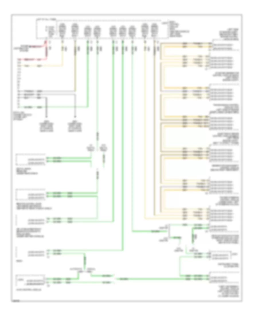
DEFOGGERS
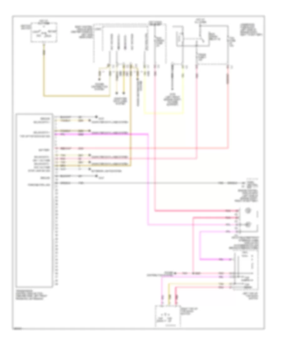
Defoggers Wiring Diagram for Saturn Aura XR 2007
List of elements for Defoggers Wiring Diagram for Saturn Aura XR 2007:
- A12
- B12
- B8 c1
- Body control module (bcm) (center console, left side near dash)
- C1 c12
- Computer data lines system
- Defog ind
- Defog switch
- Driver outside rearview mirror
- F2 c4
- G201 (under dash, right side of console, near floor)
- G301 (behind top right rear seat back)
- G302 (behind top left rear seat back)
- G303 (behind left front kick panel)
- Hot at all times
- Htd mir fuse 24 10a
- Hvac control module (automatic a/c)
- Hvac control module (manual a/c)
- Logic
- Low spd gmlan serial data
- Low speed gmlan ser data
- Nca
- Passenger outside rearview mirror
- R/wdo defog relay
- Rear fuse block (behind left rear wheel well)
- Rear window defogger grid
- Rr defog fuse 23 30a
- Rr defog rly ctrl
- Rr defog sw sig
- Tan
ELECTRONIC POWER STEERING
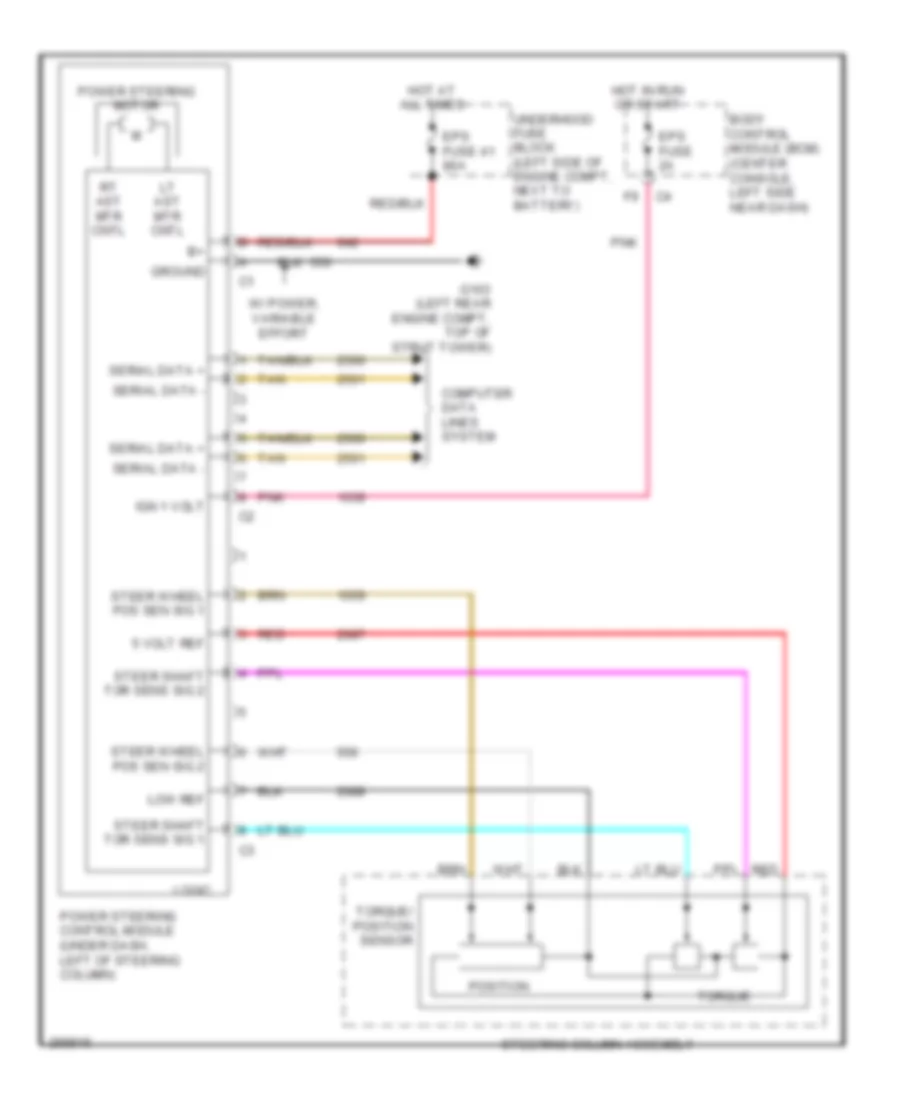
Electronic Power Steering Wiring Diagram for Saturn Aura XR 2007
List of elements for Electronic Power Steering Wiring Diagram for Saturn Aura XR 2007:
- 5 volt ref
- Body control module (bcm) (center console, left side near dash)
- Computer data lines system
- Eps fuse 2a
- Eps fuse 41 80a
- G103 (left rear engine compt, top of strut tower)
- Ground
- Hot at all times
- Hot in run or start
- Ign 1 volt
- Logic
- Low ref
- Lt ast mtr cntl
- Pnk
- Position
- Power steering control module (under dash, left of steering column)
- Power steering motor
- Red
- Rt ast mtr cntl
- Serial data +
- Serial data -
- Steer shaft tor sens sig 1
- Steer shaft tor sens sig 2
- Steer wheel pos sen sig 1
- Steer wheel pos sen sig 2
- Steering column assembly
- Tan
- Torque
- Torque/ position sensor
- Underhood fuse block (left side of engine compt, next to battery)
- W/ power, variable effort
ENGINE PERFORMANCE
2.4L VIN 5
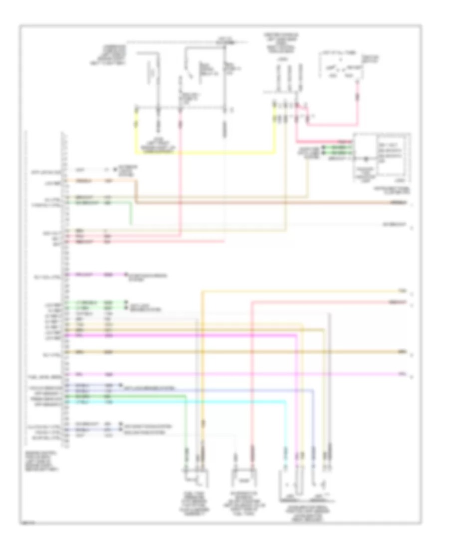
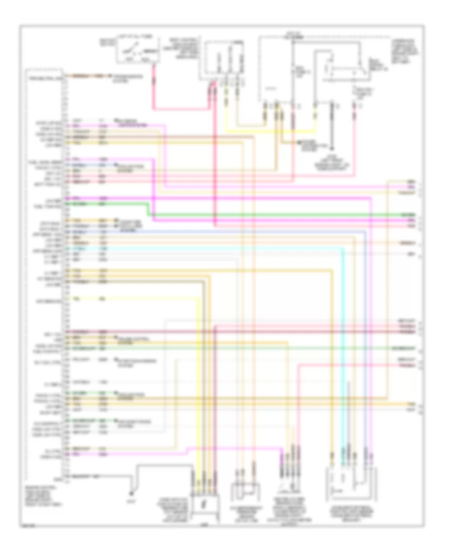
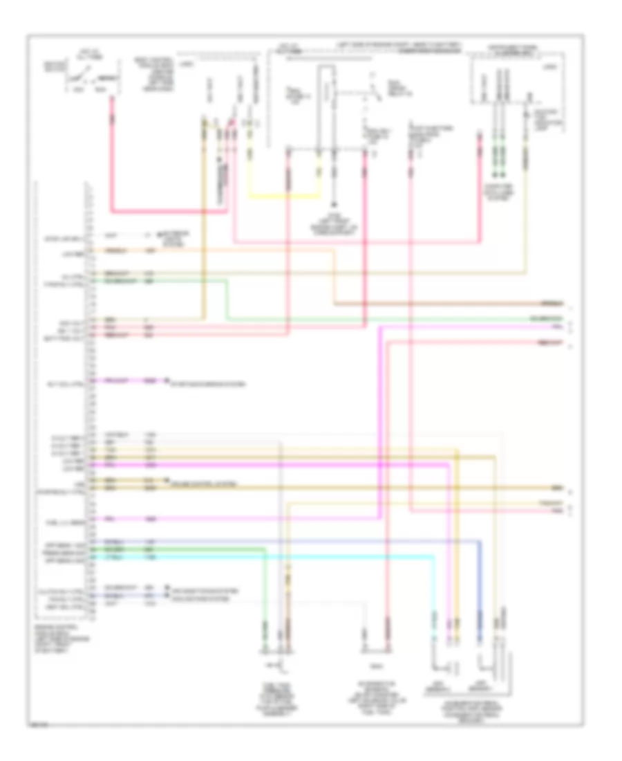
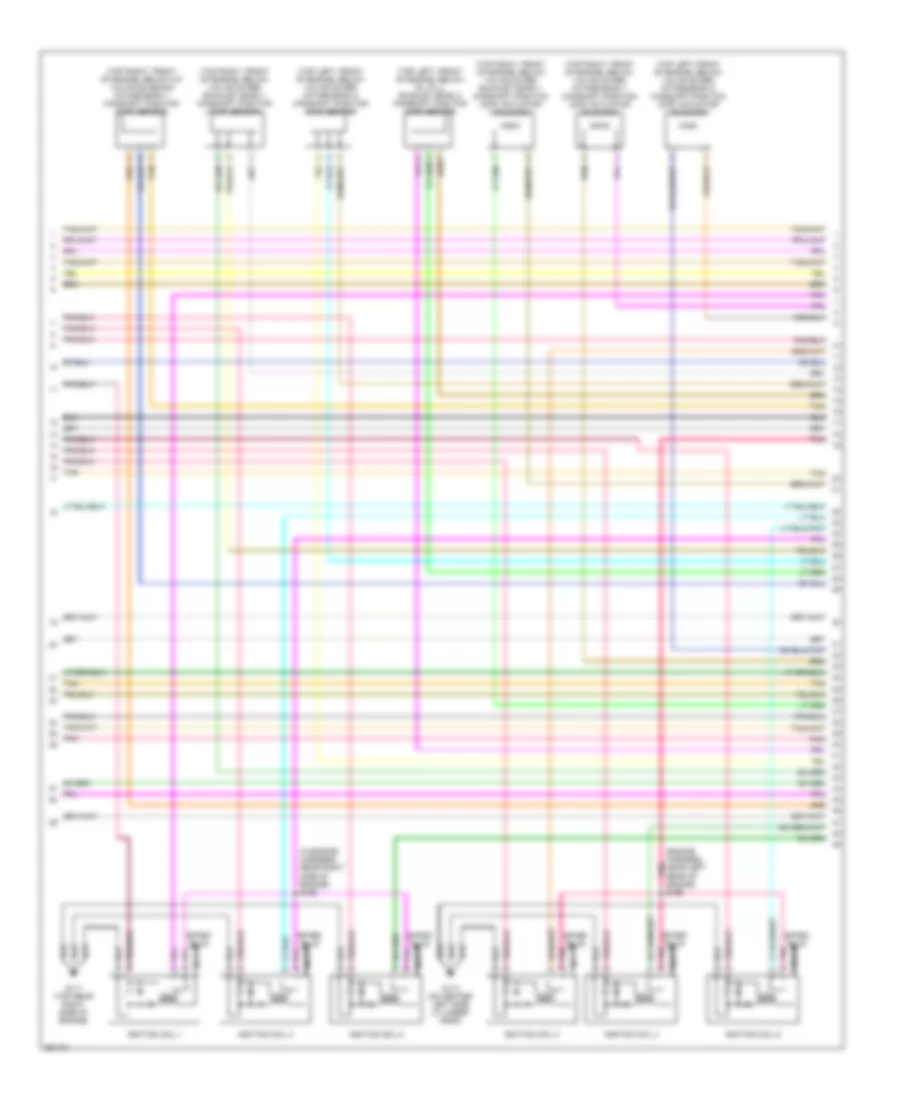
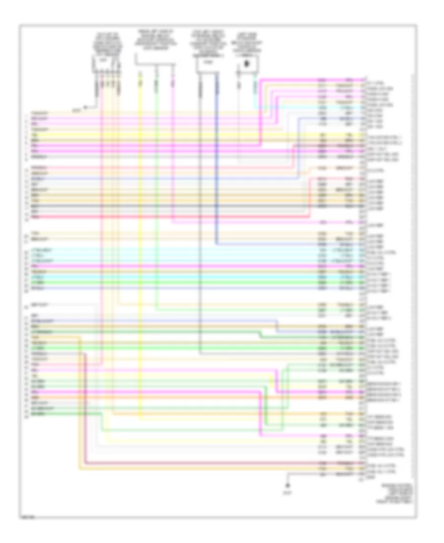
2.4L VIN 5, Engine Performance Wiring Diagram (1 of 4) for Saturn Aura XR 2007
List of elements for 2.4L VIN 5, Engine Performance Wiring Diagram (1 of 4) for Saturn Aura XR 2007:
- (center console, left side near dash) body control module (bcm)
- 5v ref
- 5v ref 1
- 5v ref 2
- Acc
- Acc volt
- Acc voltage
- Accelerator pedal position (app) sensor (accelerator pedal bracket)
- Air conditioning system
- Anti-lock brakes system
- App sensor 1
- App sensor 2
- Bat
- C10
- Clutch rly ctrl
- Computer data lines system
- Cooling fans system
- Ecm fuse 13 10a
- Ecm ign 1 fuse 16 10a
- Engine control module (ecm) (left side of engine compt, behind battery)
- Evap sol ctrl
- Evaporative emission (evap) canister vent solenoid valve (right side of fuel tank)
- Exterior lights system
- F pmp rly ctrl
- Fan rly ctrl
- Fuel level sens
- Fuel tank pressure (ftp) sensor (top of fuel pump & sender assembly)
- G109 (left front engine compt, on core support)
- Gmlan data
- Hot at all times
- Ign
- Ign 1
- Ign 1 volt
- Ign 1 voltage
- Ignition switch
- Instrument panel cluster (ipc)
- Logic
- Low ref
- Malfunc- tion indicator lamp
- Mil ctrl
- Off
- Pnk
- Press sens sig
- Rly coil ctrl
- Rly ctrl
- Run
- Run/ crank relay 32
- Start
- Starting/charging system
- Stp lmp sw sig
- Tan
- Underhood fuse block (left side of engine compt, next to battery)
- Vacuum sens sig
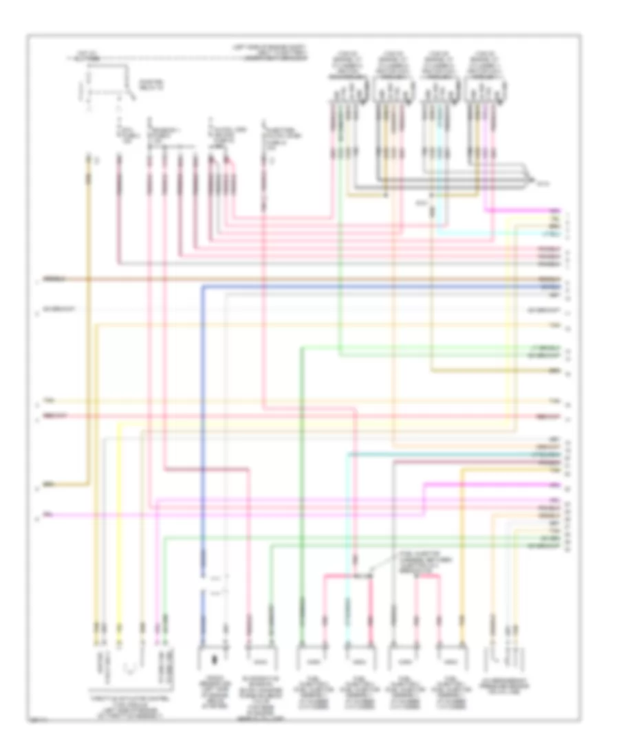
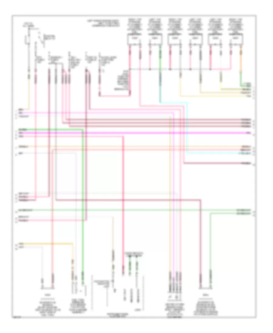
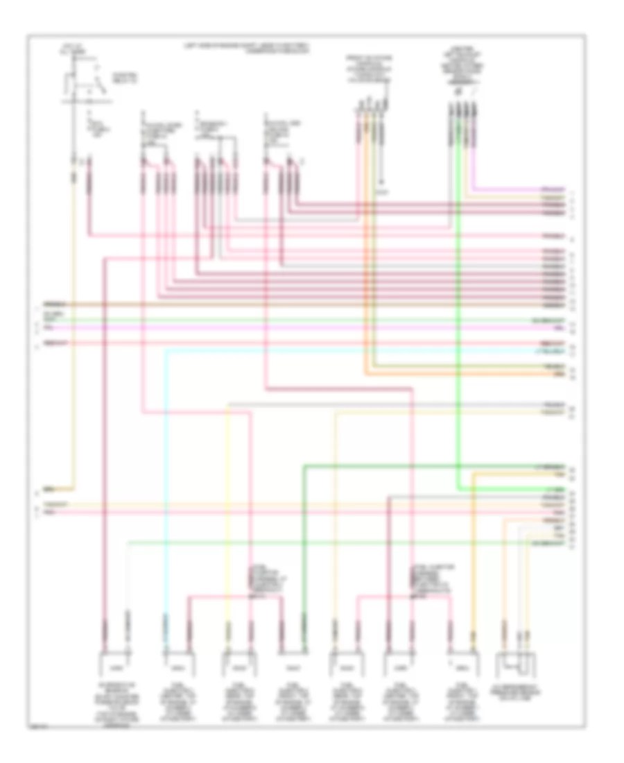
2.4L VIN 5, Engine Performance Wiring Diagram (2 of 4) for Saturn Aura XR 2007
List of elements for 2.4L VIN 5, Engine Performance Wiring Diagram (2 of 4) for Saturn Aura XR 2007:
- (fuel injector harness, between injector 2 & 3 breakouts)
- (left side of engine compt, next to battery) underhood fuse block
- (top of engine, at cylinder 1) ignition coil/ module 1
- (top of engine, at cylinder 2) ignition coil/ module 2
- (top of engine, at cylinder 3) ignition coil/ module 3
- (top of engine, at cylinder 4) ignition coil/module 4
- 5 volt ref 2
- A/c refrigerant pressure sensor (on a/c line)
- A10
- B11
- C11
- Cs gnd
- Ctrl
- D11
- E11
- Emission 1 fuse 6 10a
- Etc fuse 2 15a
- Evaporative emission (evap) canister purge solenoid valve (top rear of engine, near oil fill cap)
- Fuel injector 1 (fuel injector assembly, at number 1 cylinder)
- Fuel injector 2 (fuel injector assembly, at number 2 cylinder)
- Fuel injector 3 (fuel injector assembly, at number 3 cylinder)
- Fuel injector 4 (fuel injector assembly, at number 4 cylinder)
- Fuse 44 10a
- G110
- Gnd
- Hot at all times
- Ign
- Inj/coil odd/ ign mod fuse 43 15a
- Injectors inj/coil even
- Knock sensor (ks) (left side of engine, above starter)
- Lo ref
- Low ref
- Pnk
- Pwr/trn relay 33
- S121
- S130
- Tan
- Throttle actuator control (tac) module (left side of engine, on throttle assembly)
- Tp sen 1 sig
- Tp sen 2 sig
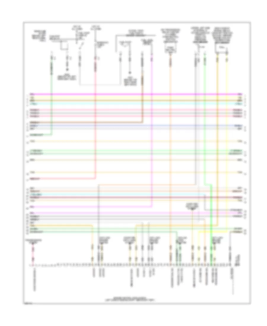
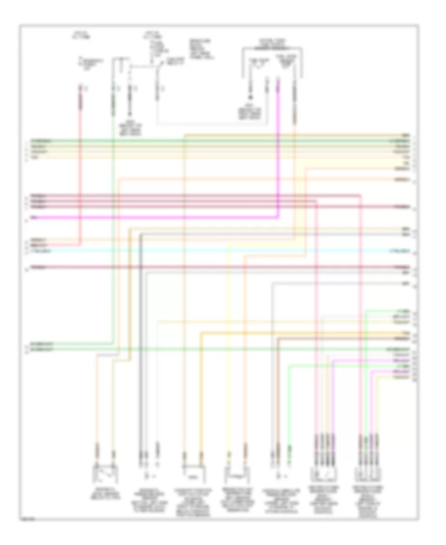
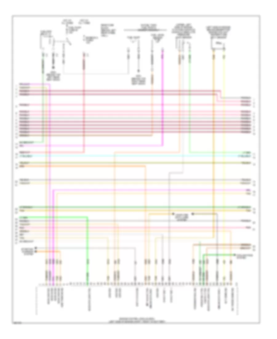
2.4L VIN 5, Engine Performance Wiring Diagram (3 of 4) for Saturn Aura XR 2007
List of elements for 2.4L VIN 5, Engine Performance Wiring Diagram (3 of 4) for Saturn Aura XR 2007:
- (in fuel tank) fuel pump & sender assembly
- (on transmission, below master cylinder) park/neutral position (pnp) switch
- (right side of engine, below camshaft position exhaust sensor) engine coolant temperature (ect) sensor
- (upper, left side of engine, in intake manifold) manifold absolute pressure (map) sensor
- 5v ref
- 5v ref 1
- 5v ref 2
- A10
- Anti-lock brakes system
- C3 oil press
- Computer data lines system
- Cooling fans system
- Ect sens sig
- Emission 2 fuse 5 10a
- Engine control module (ecm) (left side of engine compt, behind battery)
- Fan rly ctrl
- Fluid press sw sig a
- Fuel level sensor
- Fuel pump
- Fuel pump fuse 25 15a
- Fuel/pmp relay 37
- G301 (behind top right rear seat back)
- G302 (behind top left rear seat back)
- Gmlan data bus +
- Gmlan data bus -
- Hot at all times
- Low ref
- Map sens sig
- Not used) (66 to 73
- Park/ neutral sig
- Park/neutral sig
- Pnk
- Press sens sig
- Purge sol ctrl
- Rear fuse block (behind left rear wheel well)
- Tan
- Transmissions system
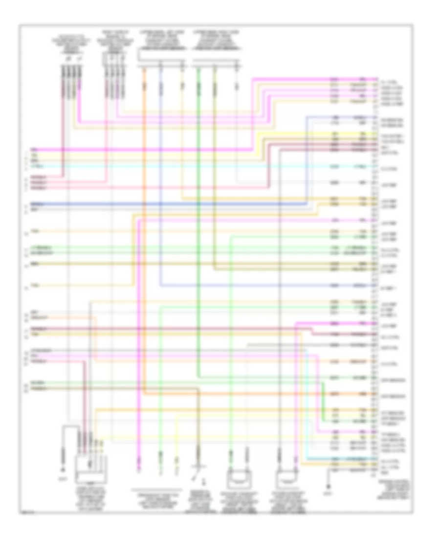
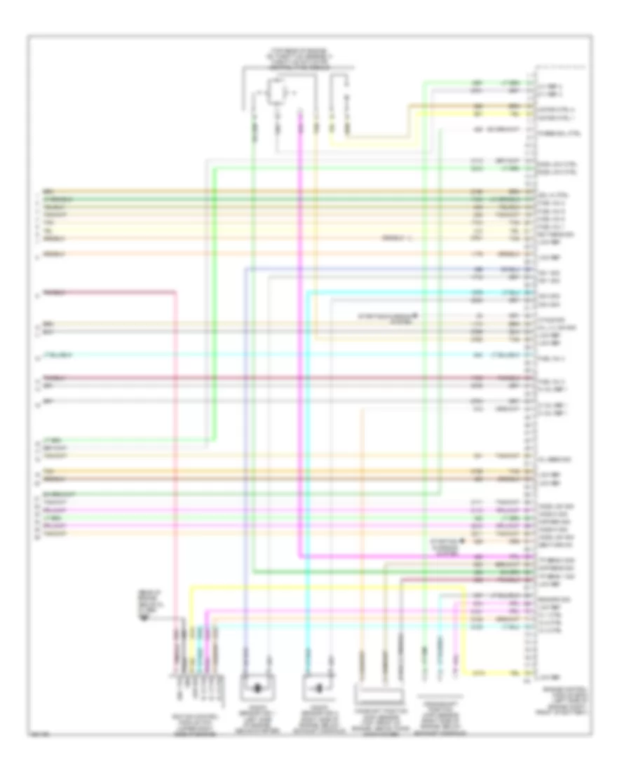
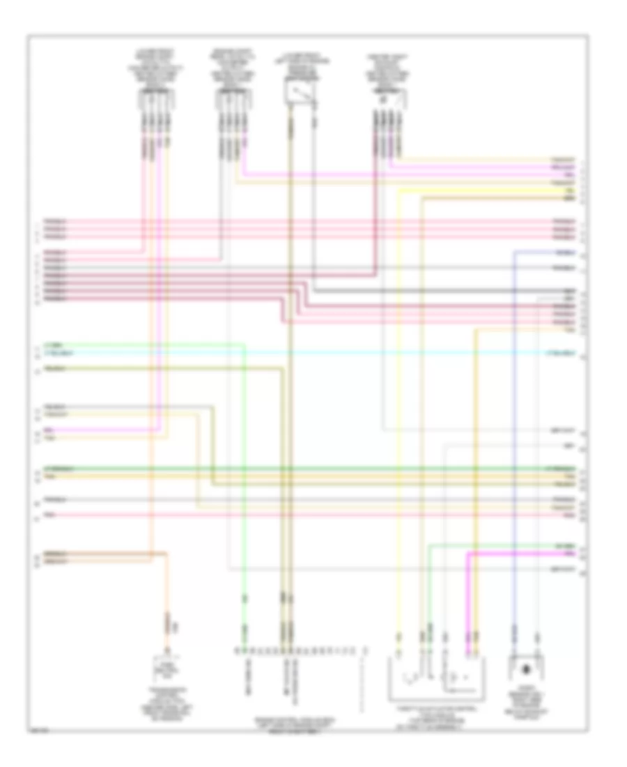
2.4L VIN 5, Engine Performance Wiring Diagram (4 of 4) for Saturn Aura XR 2007
List of elements for 2.4L VIN 5, Engine Performance Wiring Diagram (4 of 4) for Saturn Aura XR 2007:
- (in catalytic converter output) heated oxygen sensor (ho2s) 2
- (right side of engine, in exhaust manifold) heated oxygen sensor (ho2s) 1
- (upper rear, left side of engine, near camshaft cover)
- (upper rear, right side of engine, near camshaft cover) exhaust camshaft position (cmp) sensor
- 5v ref
- 5v ref 1
- 5v ref 2
- Ckp sens sig
- Cmp ctrl
- Cmp sens sig
- Crankshaft position (ckp) sensor (left side of engine above starter)
- Engine control module (ecm) (left side of engine compt, behind battery)
- Engine oil pressure (eop) switch (left side of engine, above starter)
- Exhaust camshaft position (cmp) actuator solenoid (front, top of engine, between camshaft covers)
- G107
- Gnd
- Ho2s hi sig
- Ho2s lo ctrl
- Ho2s lo ref
- Ho2s lo sig
- Iat
- Iat sens sig
- Ic 1 ctrl
- Ic 2 ctrl
- Ic 3 ctrl
- Ic 4 ctrl
- Ign 1
- Inj 1 ctrl
- Inj 2 ctrl
- Inj 3 ctrl
- Inj 4 ctrl
- Intake camshaft position (cmp) actuator solenoid (front, top of engine, between camshaft covers)
- Intake camshaft position (cmp) sensor
- Ks sens sig
- Low ref
- Maf
- Maf sens sig
- Mass air flow (maf)/intake air temperature (iat) sensor (maf: outlet of air cleaner)
- Nca
- Tac motor 1
- Tac motor 2
- Tan
- Tp sens 1
- Tp sens 2
3.5L VIN N
3.5L VIN N, Engine Performance Wiring Diagram (1 of 4) for Saturn Aura XR 2007
List of elements for 3.5L VIN N, Engine Performance Wiring Diagram (1 of 4) for Saturn Aura XR 2007:
- 5 v ref 1
- 5 v ref 2
- A/c compr rly
- A/c ref sig
- A/c refrigerant pressure sensor (on a/c line)
- Acc
- Acc vol
- Acc volt
- Accelerator pedal position (app) sensor (accelerator pedal bracket)
- Air conditioning system
- App sens 1 sig
- App sens 2 sig
- Batt pos vol
- Body control module (bcm) (center console, left side near dash)
- C10
- Computer data lines system
- Cooling fans system
- Cruise control system
- Data bus +
- Data bus -
- Ecm fuse 13 10a
- Ecm ign 1 fuse 16 10a
- Engine control module (ecm) (left side of engine compt, front of battery)
- Evap vent
- Exterior lights system
- Fan rly ctrl
- Fuel level sens
- Fuel pump rly
- Fuel tank sig
- G107
- G109 (left front engine compt, on core support)
- Gnd
- Heated oxygen sensor (ho2s) bank 2 sensor 2 (lower front of engine compt, catalytic converter output)
- Ho2s hi sig
- Ho2s low ctrl
- Ho2s low sig
- Hot at all times
- Iat
- Iat sens sig
- Ign 1 vol
- Ign 1 volt
- Ignition switch
- Logic
- Low ref
- Maf
- Maf sens sig
- Mass air flow (maf)/intake air temperature (iat) sensor (outlet of air cleaner)
- Mil ctrl
- Nca
- Off
- Pnk
- Power distribution system
- Prk/neutral sig
- Pwr rly ctrl
- Rly coil ctrl
- Run
- Run/ crank relay 32
- Start
- Starting/charging system
- Stop lmp sig
- Tan
- Tan a
- Transmissions system
- Underhood fuse block (left side of engine compt, next to battery)
- Vss
3.5L VIN N, Engine Performance Wiring Diagram (2 of 4) for Saturn Aura XR 2007
List of elements for 3.5L VIN N, Engine Performance Wiring Diagram (2 of 4) for Saturn Aura XR 2007:
- (left side of engine compt, next to battery) underhood fuse block
- (left, top of engine, at number 4 cylinder intake port) fuel injector 4
- (left, top of engine, at number 5 cylinder intake port) fuel injector 5
- (left, top of engine, at number 6 cylinder intake port) fuel injector 6
- (right, top of engine, at number 1 cylinder intake port) fuel injector 1
- (right, top of engine, at number 2 cylinder intake port) fuel injector 2
- (right, top of engine, at number 3 cylinder intake port) fuel injector 3
- A10
- B11
- C11
- Computer data lines system
- D11
- Emission 1 fuse 6 10a
- Etc fuse 2 15a
- Evaporative emission (evap) canister purge solenoid valve (top rear of engine, on intake manifold)
- Evaporative emission (evap) canister vent solenoid valve (right side of fuel tank)
- Fuel tank pressure (ftp) sensor (top of fuel pump & sender assembly)
- Gmlan data
- Heated oxygen sensor (ho2s) bank 1 sensor 2 (in outlet of catalytic converter)
- Hot at all times
- Ign
- Ign 1 ecm ign 1 bas ign fuse 3 15a
- Ign 1 volt
- Inj/coil even injectors fuse 44 10a
- Instrument panel cluster (ipc)
- Logic
- Malfunction indicator lamp
- Nca
- Pnk
- Post o2 fuse 45 10a
- Pwr/trn relay 33
- S130 (fuel injector harness, between injector 2 & 3 breakouts) pnk
- Tan
3.5L VIN N, Engine Performance Wiring Diagram (3 of 4) for Saturn Aura XR 2007
List of elements for 3.5L VIN N, Engine Performance Wiring Diagram (3 of 4) for Saturn Aura XR 2007:
- (in fuel tank) fuel pump & sender assembly
- A10
- Camshaft position (cmp) actuator solenoid (lower left front of engine, below camshaft position sensor)
- Emission 2 fuse 5 10a
- Engine coolant temperature (ect) sensor (in cylinder head, below coolant reservoir)
- Engine oil level sensor (below oil pan)
- Engine oil pressure (eop) sensor (bottom, left side of engine, on oil filter housing)
- Fuel level sensor
- Fuel pump
- Fuel pump fuse 25 15a
- Fuel/pmp relay 37
- G301 (behind top right rear seat back)
- G302 (behind top left rear seat back)
- Heated oxygen sensor (ho2s) bank 1 sensor 1 (center, rear exhaust manifold)
- Heated oxygen sensor (ho2s) bank 2 sensor 1 (left side of engine, in exhaust manifold)
- Hot at all times
- Manifold absolute pressure (map) sensor (upper, left side of engine, in intake manifold)
- Nca
- Rear fuse block (behind left rear wheel well)
- Tan
3.5L VIN N, Engine Performance Wiring Diagram (4 of 4) for Saturn Aura XR 2007
List of elements for 3.5L VIN N, Engine Performance Wiring Diagram (4 of 4) for Saturn Aura XR 2007:
- (rear of engine, above oil filter) g106
- (top rear of engine, on throttle assembly) throttle actuator control (tac) module
- 5 v ref 2
- 5 vol ref 1
- Camshaft position (cmp) sensor (top, front of engine, above timing chain cover)
- Cmp sens sig
- Crankshaft position (ckp) sensor (right side of engine, below exhaust manifold)
- Cycle sig
- Ect sens sig
- Eng spd sig
- Engine control module (ecm) (left side of engine compt, front of battery)
- Fuel inj 1
- Fuel inj 2
- Fuel inj 3
- Fuel inj 4
- Fuel inj 5
- Fuel inj 6
- Gen turn on
- Gnd
- Ho2s hi sig
- Ho2s low ctrl
- Ho2s low sig
- Ic 1 ctrl
- Ic 2 ctrl
- Ic 3 ctrl
- Ign 1 vol
- Ignition control module (icm) (upper right side of engine)
- Knock sensor (ks) 1 (left side of engine, above starter)
- Knock sensor (ks) 2 (right side of engine, below exhaust manifold)
- Ks 1 sig
- Ks 2 sig
- Low ref
- Map sen sig
- Motor ctrl 1
- Motor ctrl 2
- Oil lvl sw sig
- Oil sens sig
- Purge sol ctrl
- Sol hi ctrl
- Starting/ charging system
- Starting/charging system
- Tan
- Tp sens 1 sig
- Tp sens 2 sig
3.6L VIN 7
3.6L VIN 7, Engine Performance Wiring Diagram (1 of 6) for Saturn Aura XR 2007
List of elements for 3.6L VIN 7, Engine Performance Wiring Diagram (1 of 6) for Saturn Aura XR 2007:
- (left side of engine compt, near to battery) underhood fuse block
- 5-volt ref 1
- 5-volt ref 2
- Acc
- Acc volt
- Accelerator pedal position (app) sensor (accelerator pedal bracket)
- Air conditioning system
- App sens 1 sig
- App sens 2 sig
- App sensor 1
- App sensor 2
- B10
- Batt pos volt
- Body control module (bcm) (center console, left side near dash)
- C10
- Clutch rly ctrl
- Computer data lines system
- Cooling fans system
- Cruise control system
- Ecm fuse 13 10a
- Ecm ign 1 fuse 16 10a
- Engine control module (ecm) (left side of engine compt, front of battery)
- Evaporative emission (evap) canister vent solenoid valve (right side of fuel tank)
- Exterior lights system
- F pmp rly ctrl
- Fan rly ctrl
- Fuel lvl sens
- Fuel tank pressure (ftp) sensor (top of fuel pump & sender assembly)
- G109 (left front engine compt, on core support)
- Gmlan data
- Hot at all times
- Ign
- Ign 1 volt
- Ignition switch
- Instrument panel cluster (ipc)
- Logic
- Low ref
- Maf injectors bas pmps fuse 5 10a
- Malfunc- tion indicator lamp
- Mil ctrl
- Off
- Pnk
- Press sens sig
- Pwrtrn rly ctrl
- Rly coil ctrl
- Run
- Run/ crank relay 32
- Start
- Starting/charging system
- Stop lmp sply
- Tan
- Transmissions system
- Vent sol ctrl
- Vss
3.6L VIN 7, Engine Performance Wiring Diagram (2 of 6) for Saturn Aura XR 2007
List of elements for 3.6L VIN 7, Engine Performance Wiring Diagram (2 of 6) for Saturn Aura XR 2007:
- (center, left exhaust manifold) heated oxygen sensor (ho2s) bank 2 sensor 1
- (front of intake manifold) intake manifold tuning (imt) valve solenoid
- (left side of engine compt, near to battery) underhood fuse block
- A/c refrigerant pressure sensor (on a/c line)
- A10
- B11
- C11
- Ctrl c
- D11
- Emission 1 fuse 6 10a
- Etc fuse 2 15a
- Evaporative emission (evap) canister purge solenoid valve (top of engine, on right intake manifold)
- Fuel injector 1 (front, top of engine, at number 1 cylinder intake port)
- Fuel injector 2 (front, top of engine, at number 2 cylinder intake port)
- Fuel injector 3 (center, top of engine, at number 3 cylinder intake port)
- Fuel injector 4 (center, top of engine, at number 4 cylinder intake port)
- Fuel injector 5 (rear, top of engine, at number 5 cylinder intake port)
- Fuel injector 6 (rear, top of engine, at number 6 cylinder intake port)
- G107
- Gnd b
- Hot at all times
- Ign a
- Inj/coil even injectors fuse 44 15a
- Inj/coil odd ign mod fuse 43 15a
- Nca
- Pnk
- Pwr/trn relay 33
- S114
- S130
- Sig d
- Tan
3.6L VIN 7, Engine Performance Wiring Diagram (3 of 6) for Saturn Aura XR 2007
List of elements for 3.6L VIN 7, Engine Performance Wiring Diagram (3 of 6) for Saturn Aura XR 2007:
- (in fuel tank) fuel pump & sender assembly
- (left side of engine, behind generator) engine coolant temperature (ect) sensor
- (upper, left side of engine, in intake manifold) manifold absolute pressure (map) sensor
- 5-volt ref 1
- A10
- C3 a/c press sens sig
- Computer data lines system
- Cooling fans system
- Duty cycle sig
- Ect sens sig
- Emission 2 fuse 5 10a
- Engine control module (ecm) (left side of engine compt, front of battery)
- Fan rly ctrl
- Fuel level sensor
- Fuel pump
- Fuel pump fuse 25 15a
- Fuel/pmp relay 37
- G301 (behind top right rear seat back)
- G302 (behind top left rear seat back)
- Gen turn on sig
- Gmlan data bus +
- Gmlan data bus -
- Ho2s hi sig
- Ho2s htr low ctrl
- Ho2s low ref
- Ho2s low sig
- Hot at all times
- Imt valve ctrl
- Low ref
- Park/neutral sig
- Pnk
- Purge sol ctrl
- Rear fuse block (behind left rear wheel well)
- Starting/ charging system
- Tan
3.6L VIN 7, Engine Performance Wiring Diagram (4 of 6) for Saturn Aura XR 2007
List of elements for 3.6L VIN 7, Engine Performance Wiring Diagram (4 of 6) for Saturn Aura XR 2007:
- (center, right exhaust manifold) heated oxygen sensor (ho2s) bank 1 sensor 1
- (engine compt rear, catalytic converter output) heated oxygen sensor (ho2s) bank 1 sensor 2
- (lower front engine compt, catalytic converter output) heated oxygen sensor (ho2s) bank 2 sensor 2
- (lower front, left side of engine) engine oil pressure (eop) switch
- Engine control module (ecm) (left side of engine compt, front of battery)
- Imt valve sig
- Knock sensor (ks) 1 (right side of engine, below exhaust manifold)
- Map sens sig
- Nca
- Oil press sw sig
- On throttle assembly)
- Park neutral sig
- Pnk
- Tan
- Throttle actuator control (tac) module (top rear of engine,
- Transmission control module (tcm) (inboard side, left front frame rail extension)
3.6L VIN 7, Engine Performance Wiring Diagram (5 of 6) for Saturn Aura XR 2007
List of elements for 3.6L VIN 7, Engine Performance Wiring Diagram (5 of 6) for Saturn Aura XR 2007:
- (engine harness, near left rear of pnk engine) s199
- (in engine harness, rear right side of engine) s198
- (top left, front of engine, below oil fill) exhaust bank 2 camshaft position (cmp) sensor
- (top left, front of engine, below valve cover) intake bank 2 camshaft position (cmp) actuator solenoid
- (top left, front of engine, below valve cover) intake bank 2 camshaft position (cmp) sensor
- (top right, front of engine, below imt valve solenoid) intake bank 1 camshaft position (cmp) sensor
- (top right, front of engine, below valve cover) exhaust bank 1 camshaft position (cmp) actuator solenoid
- (top right, front of engine, below valve cover) exhaust bank 1 camshaft position (cmp) sensor
- (top right, front of engine, below valve cover) intake bank 1 camshaft position (cmp) actuator solenoid
- G111 (top rear right side of engine)
- G113 (on center left side cylinder head)
- Ignition coil 1
- Ignition coil 2
- Ignition coil 3
- Ignition coil 4
- Ignition coil 5
- Ignition coil 6
- Nca
- Pnk
- Pnk b
- Spark plug
- Tan
3.6L VIN 7, Engine Performance Wiring Diagram (6 of 6) for Saturn Aura XR 2007
List of elements for 3.6L VIN 7, Engine Performance Wiring Diagram (6 of 6) for Saturn Aura XR 2007:
- (left side of engine, below exhaust manifold) knock sensor (ks) 2
- (outlet of air cleaner) mass air flow (maf)/intake air temperature (iat) sensor
- (rear left side of engine, below exhaust manifold) crankshaft position (ckp) sensor
- (top left, front of engine, below valve cover) camshaft position (cmp) actuator solenoid exhaust bank 2
- 5-volt ref
- 5-volt ref 1
- 5-volt ref 2
- Ckp sens sig
- Cmp act sol sig
- Engine control module (ecm) (left side of engine compt, front of battery)
- Fuel inj 1 ctrl
- Fuel inj 2 ctrl
- Fuel inj 3 ctrl
- Fuel inj 4 ctrl
- Fuel inj 5 ctrl
- Fuel inj 6 ctrl
- G107
- Gnd
- Ho2s hi sig
- Ho2s htr low ctrl
- Ho2s low sig
- Iat
- Iat sens sig
- Ic 1 ctrl
- Ic 2 ctrl
- Ic 3 ctrl
- Ic 4 ctrl
- Ic 5 ctrl
- Ic 6 ctrl
- Ign 1 volt
- Ks 1 sig
- Ks 2 sig
- Low ref
- Maf
- Maf sens sig
- Pnk
- Sens sig exh bk 1
- Sens sig exh bk 2
- Sens sig int bk 1
- Sens sig int bk 2
- Tac motor ctrl 1
- Tac motor ctrl 2
- Tan
- Tp sens 1 sig
- Tp sens 2 sig
EXTERIOR LIGHTS
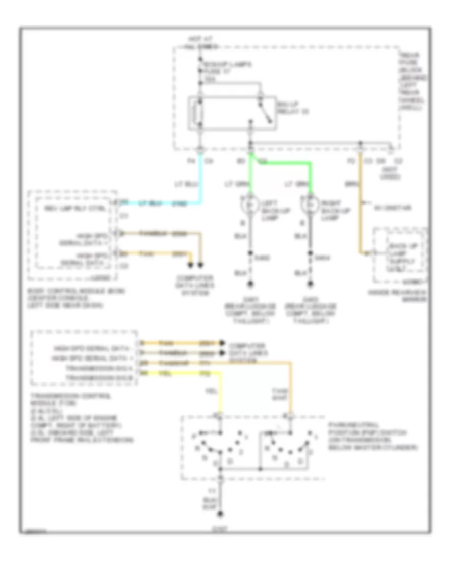
Back-up Lamps Wiring Diagram for Saturn Aura XR 2007
List of elements for Back-up Lamps Wiring Diagram for Saturn Aura XR 2007:
- (not used)
- B/u lp relay 33
- Bck/up lamps fuse 17 10a
- Body control module (bcm) (center console, left side near dash)
- Computer data lines system
- G107
- G401 (rear luggage compt, below taillight)
- G403 (rear luggage compt, below taillight)
- High spd serial data +
- High spd serial data -
- Hot at all times
- Inside rearview mirror
- Left back-up lamp
- Logic
- Park/neutral position (pnp) switch (on transmission, below master cylinder)
- Rear fuse block (behind left rear wheel well)
- Rev lmp rly ctrl
- Right back-up lamp
- S402
- S404
- Tan
- Transmission control module (tcm) (2.4l/3.5l) (2.4l: left side of engine compt, right of battery) (3.5l: inboard side, left front frame rail extension)
- Transmission sig a
- Transmission sig b
- W/ onstar
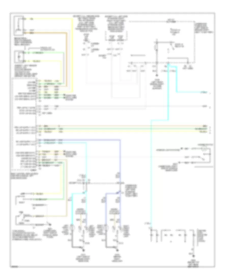
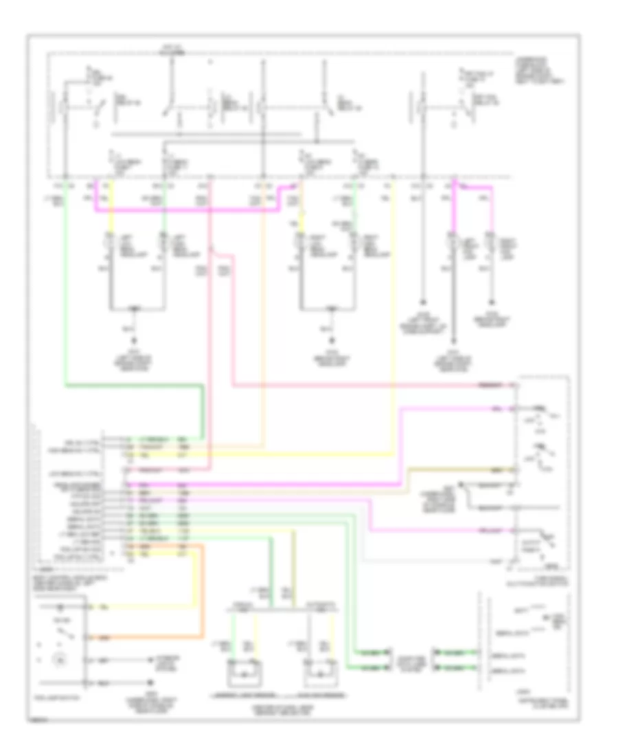
Exterior Lamps Wiring Diagram (1 of 2) for Saturn Aura XR 2007
List of elements for Exterior Lamps Wiring Diagram (1 of 2) for Saturn Aura XR 2007:
- (except 2.4l: inboard side, left front frame rail extension) (2.4l: left side of engine compt, right of battery) transmission control module (tcm)
- (except 2.4l: left side of engine compt, front of battery) (2.4l: left side of engine compt, behind battery) engine control module (ecm)
- (not used)
- 3.5l
- 4 speed a/t
- 5v ref
- 6 speed a/t
- A left front turn signal lamp
- A right front turn signal b lamp
- A12
- Ambient light sensor (manual a/c) sunload sensor (automatic a/c) (center of dash, near defrost deflector)
- Auto
- B3 (except 2.4l)
- Body control module (bcm) (center console, left side near dash)
- Brake pedal position sensor (right side brake pedal bracket)
- Brk pos sens sig
- C10
- Center high mounted stop lamp (chmsl)
- Computer data lines system
- D3 (2.4l)
- Except 3.5l
- G101 (left side of engine compt, near g109)
- G102 (behind right headlamp)
- G109 (left front engine compt, on core support)
- G201 (under dash, right side of console, near floor)
- G203 (under dash, right side of console near floor)
- G302 (behind top left rear seat back)
- Hazard sw sig
- Hazard switch
- Head
- High spd ser data +
- High spd ser data -
- Hot at all times
- Inform- ation not available
- Interior lights system
- Left
- Left front park/ turn signal lamp
- Logic
- Low ref
- Low spd serial data
- Lt turn sw sig
- Manual a/c automatic a/c
- Off
- Park
- Prk lmp rly cntrl
- Prk lmp sw sig
- Right
- Right front park/ turn signal lamp
- Rt turn sw sig
- S109
- S110
- Sens sig
- Stop lmp sw sig
- Stop lp fuse 47 10a
- Stop lp relay 49
- Tan
- Turn signal/ multifunction switch (steering column, below inflatable restraint steering wheel module coil)
- Underhood fuse block (left side of engine compt, next to battery)
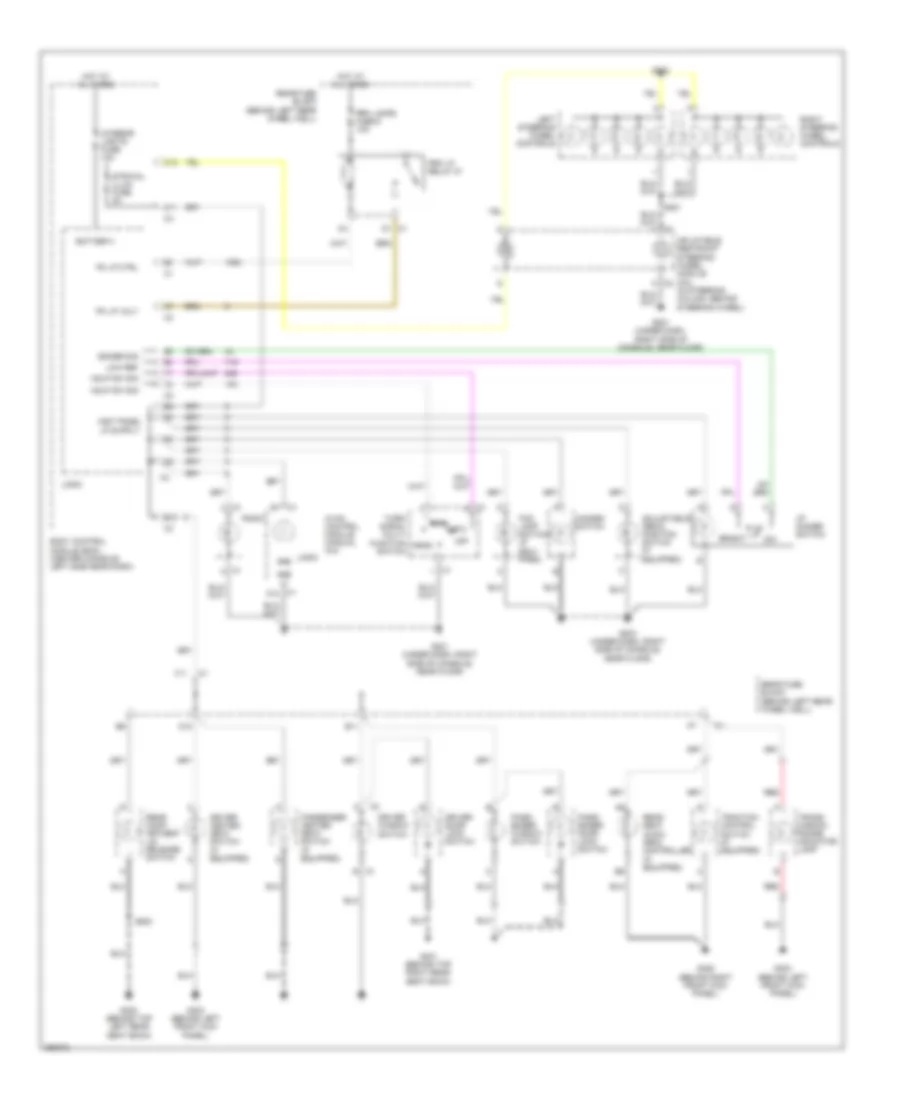
Exterior Lamps Wiring Diagram (2 of 2) for Saturn Aura XR 2007
List of elements for Exterior Lamps Wiring Diagram (2 of 2) for Saturn Aura XR 2007:
- 3.5l
- Batt
- Batt positive volt
- Body control module (bcm) (center console, left side near dash)
- C11
- C12
- C4 f1
- Chime
- Cluster/ theft fuse 10a
- Computer data lines system
- Engine control module (ecm) (except 2.4l: left side of engine compt, front of battery) (2.4l: left side of engine compt, behind battery)
- Except 3.5l
- G101 (left side of engine compt, near g109)
- G102 (behind right headlamp)
- G401 (rear luggage compt, below taillight)
- G403 (rear luggage compt, below taillight)
- High spd serial data +
- High spd serial data -
- Hot at all times
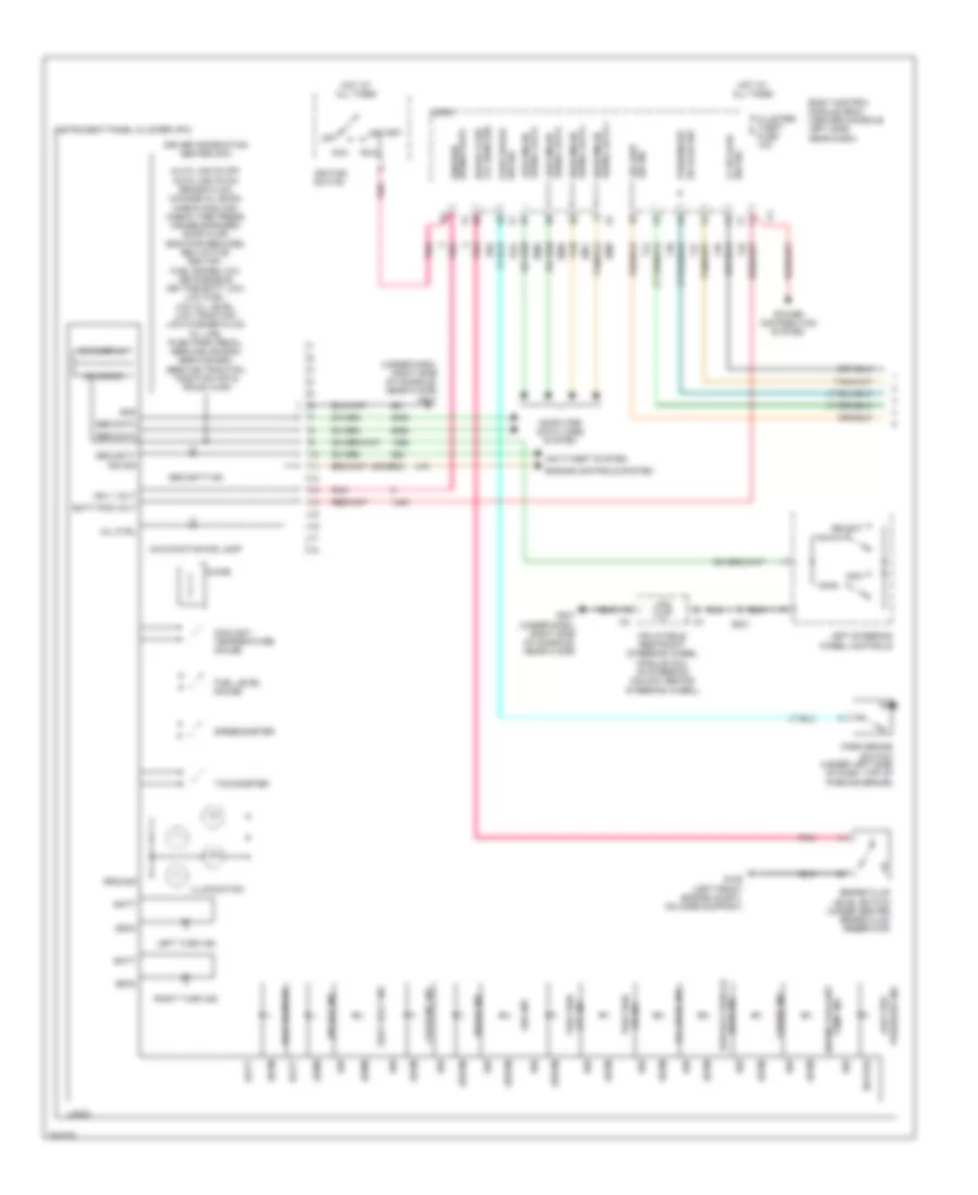
- Instrument panel cluster (ipc)
- Left front marker lamp
- Left rear marker lamp
- Left rear turn signal lamp
- Left tail/ stop lamp
- Left turn ind
- License lamp
- Logic
- Low spd serial data
- Prk lamps fuse 6 10a
- Prk lp relay 27
- Rear fuse block (behind left rear wheel well)
- Rear seat audio (rsa) controller
- Right front marker lamp
- Right rear marker lamp
- Right rear turn signal lamp
- Right tail/ stop lamp
- Right turn ind
- S109
- S110
- S402
- S404
- S406
- S407
- Serial data
- Stop
- Tail
- Tan
- Underhood fuse block (left side of engine compt, next to battery)
- W/ right rear seat & earphone jacks radio control
GROUND DISTRIBUTION
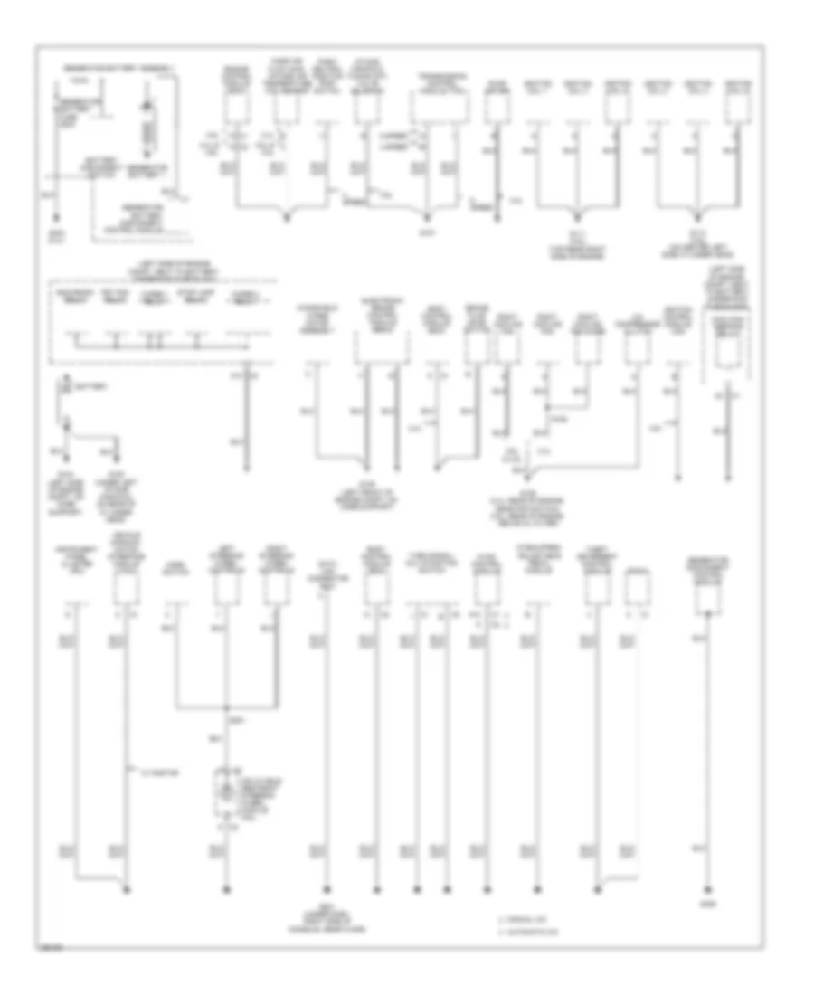
Ground Distribution Wiring Diagram (1 of 3) for Saturn Aura XR 2007
List of elements for Ground Distribution Wiring Diagram (1 of 3) for Saturn Aura XR 2007:
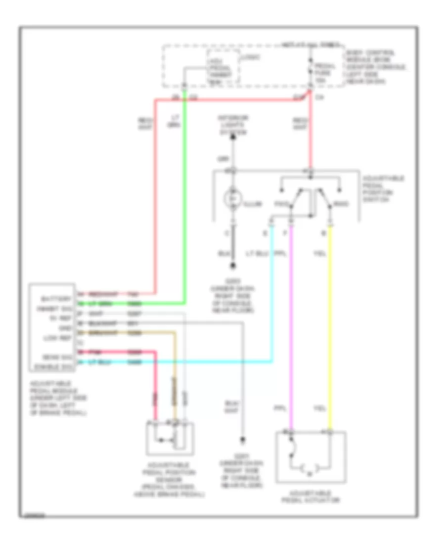
- (if equipped) adjustable pedal module
- (left side of engine compt, next to battery) underhood fuse block
- 2.4l
- 2.4l & 3.6l
- 3.5l
- 3.6l
- 3.6l & 3.5l
- 4 speed
- 6 speed
- A/c compressor clutch
- A12
- Automatic a/c
- Battery
- Battery disconnect control module
- Battery disconnect switch
- Body control module (bcm)
- Brake fluid level switch
- C10
- Cool/fan ser/par relay
- Data link connector (dlc)
- Electronic brake control module (ebcm)
- Engine control module (ecm)
- Frt fog relay
- G104 (left side of engine compt, on core support)
- G105 (under left intake manifold, on rear of cylinder head)
- G106 (2.4l: rear of engine, near pnp switch) (3.5l: rear of engine, above oil filter)
- G107
- G109 (left front of engine compt, on core support)
- G111 (3.6l) (top rear right side of engine)
- G113 (3.6l) (on center left side cylinder head)
- G201 (under dash, right side of console, near floor)
- G306
- G402 (2.4l)
- Generator
- Generator battery 1
- Generator battery assembly
- Generator battery fuse 200a
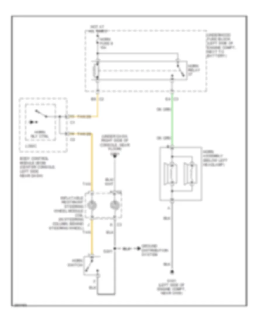
- Generator disconnect control module
- Horn switch
- Hvac control module
- Ignition coil 1
- Ignition coil 2
- Ignition coil 3
- Ignition coil 4
- Ignition coil 5
- Ignition coil 6
- Ignition control module (icm)
- Inflatable restraint steering wheel module coil
- Instrument panel cluster (ipc)
- Intake manifold tuning (imt) valve solenoid
- Left steering wheel controls
- Manual a/c
- Mass air flow (maf) /intake air temperature (iat) sensor
- Park/ neutral position (pnp) switch
- Pump driver
- Radio
- Right cooling fan
- Right cooling fan diode
- Right steering wheel controls
- Run/crank relay
- S152
- S201
- Speed
- Stop lamp relay
- Theft deterrent control module
- Transmission control module (tcm)
- Turn signal/ multifunction switch
- Vehicle communi- cation interface module (vcim)
- W/ onstar
- Windshield wiper motor assembly
- Wiper 1 relay
- Wiper 2 relay
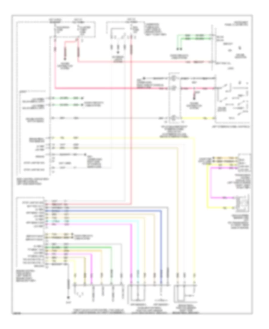
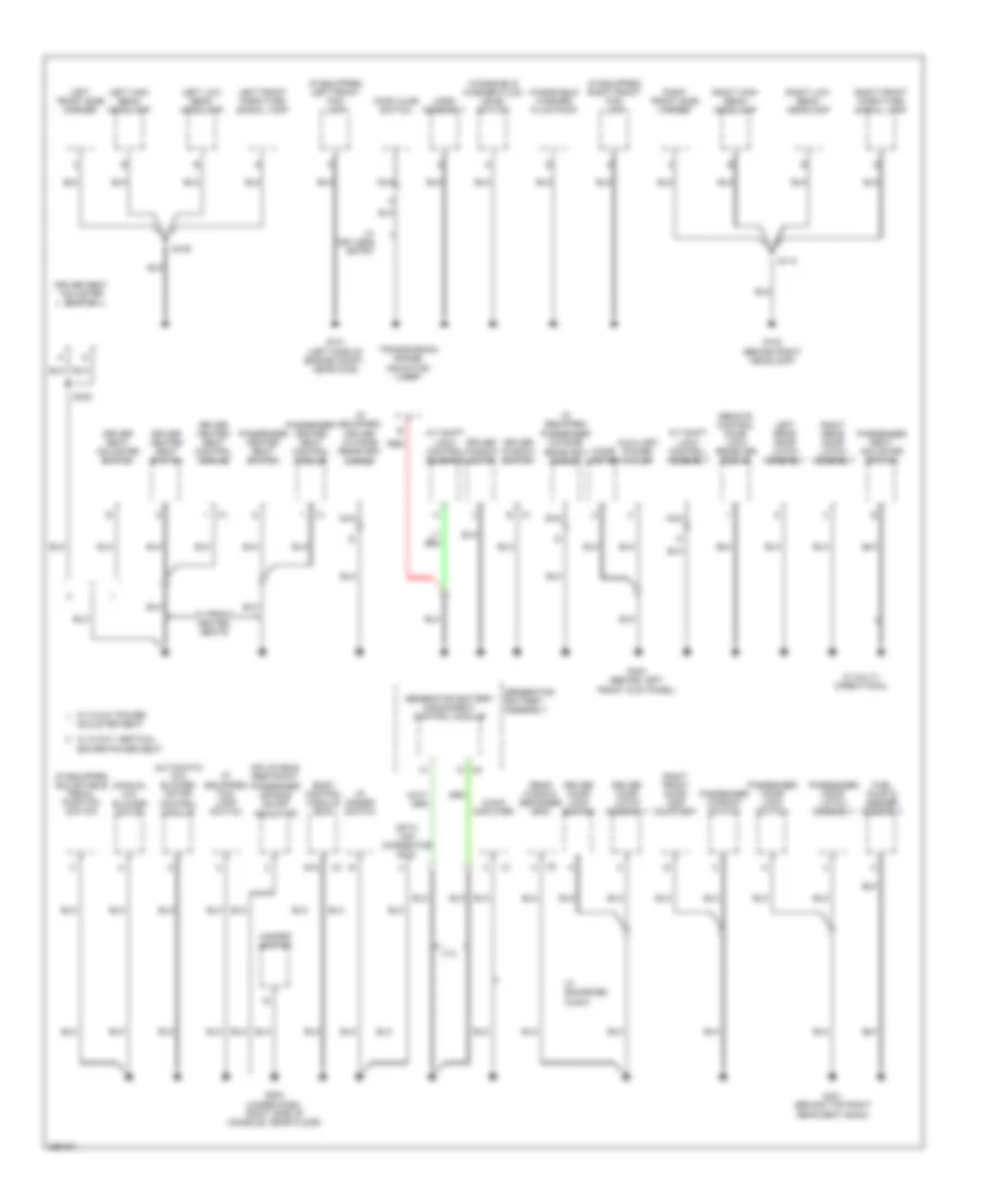
Ground Distribution Wiring Diagram (2 of 3) for Saturn Aura XR 2007
List of elements for Ground Distribution Wiring Diagram (2 of 3) for Saturn Aura XR 2007:
- (automatic a/c) blower motor control module
- (if equipped) adjustable pedal position switch
- (if equipped) driver outside rearview mirror
- (if equipped) fog lamp switch
- (if equipped) left front fog lamp
- (if equipped) passenger outside rearview mirror
- (if equipped) right front fog lamp
- (manual a/c) blower motor
- 2.4l
- A/t shift lock control assembly
- A/t shift lock control solenoid
- Adjuster seat
- Audio amplifier
- Auxiliary power outlet
- Body control module (bcm)
- Cigar lighter
- Data link connector (dlc)
- Driver door latch assembly
- Driver door lock switch
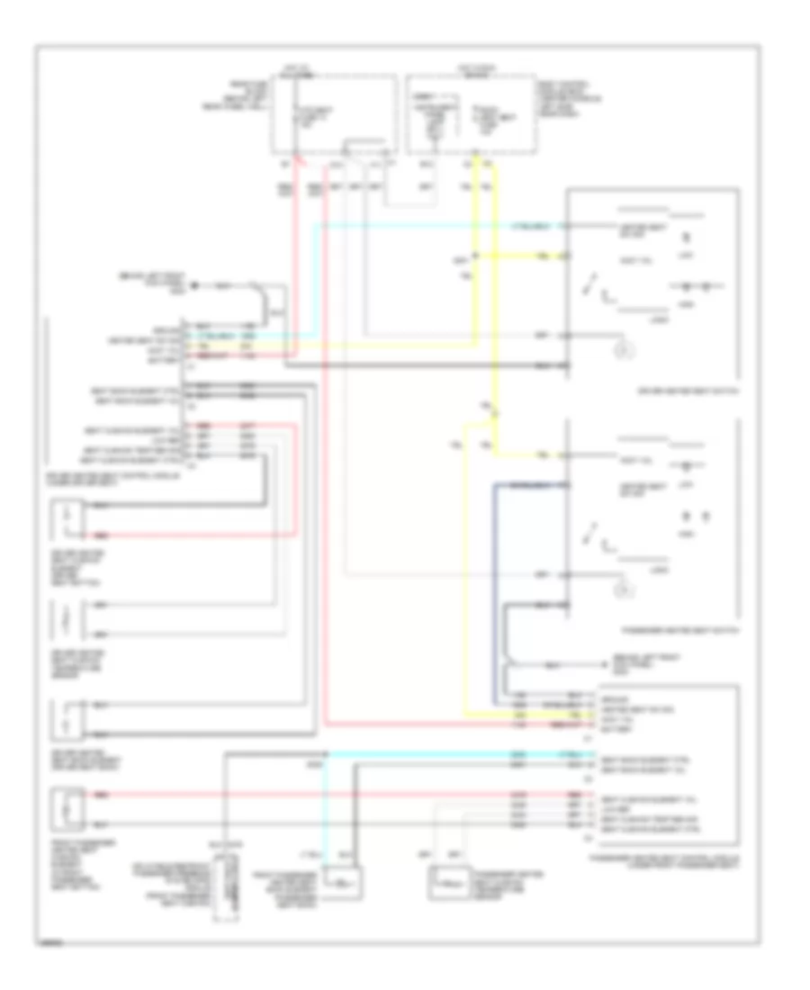
- Driver heated seat control module
- Driver heated seat switch
- Driver seat adjuster switch
- Driver window motor
- Driver window switch
- E12
- Fuel pump & sender assembly
- G101 (left side of engine compt, near g109)
- G102 (behind right headlamp)
- G203 (under dash, right side of console, near floor)
- G301 (behind top right rear seat back)
- G303 (behind left front kick panel)
- Generator battery assembly
- Generator battery disconnect control module
- Hazard switch
- Hood ajar switch
- Horn assembly
- I/p dimmer switch
- Inflatable restraint passenger air bag on/off indicator
- Left front park/turn signal lamp
- Left front side marker
- Left high beam headlamp
- Left low beam headlamp
- Left rear door latch assembly
- Nca
- Passenger door latch assembly
- Passenger door lock switch
- Passenger heated seat control module
- Passenger heated seat switch
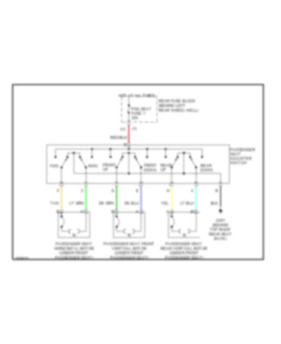
- Passenger seat adjuster switch
- Passenger window switch
- Rear window defogger grid
- Red
- Remote control door lock receiver (rcdlr)
- Right front door lamp courtesy
- Right front park/turn signal lamp
- Right front side marker
- Right high beam headlamp
- Right low beam headlamp
- Right rear door latch assembly
- S109
- S110
- S302
- Transmission range indicator lamp
- W/ 2-way vertical driver power seat
- W/ 8-way power
- W/ enhanced audio
- W/ front heated seats
- W/ keyless entry
- W/ multi- directional
- Windshield washer fluid level switch
- Windshield washer fluid pump
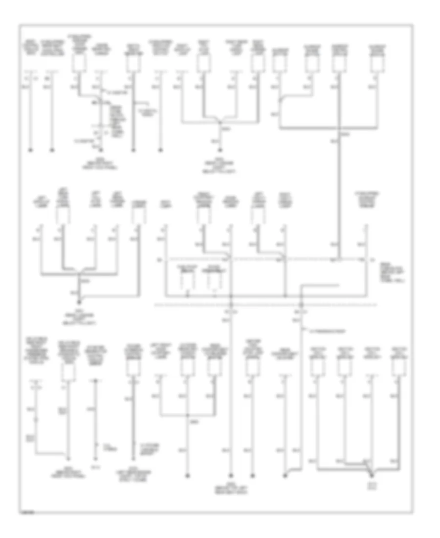
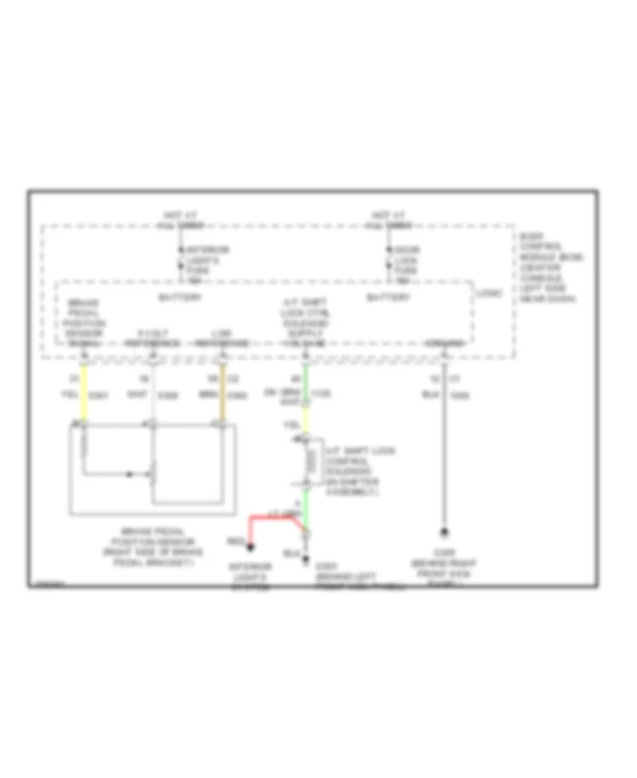
Ground Distribution Wiring Diagram (3 of 3) for Saturn Aura XR 2007
List of elements for Ground Distribution Wiring Diagram (3 of 3) for Saturn Aura XR 2007:
- (if equipped) garage door opener (gdo)
- (if equipped) rear seat audio (rsa) controller
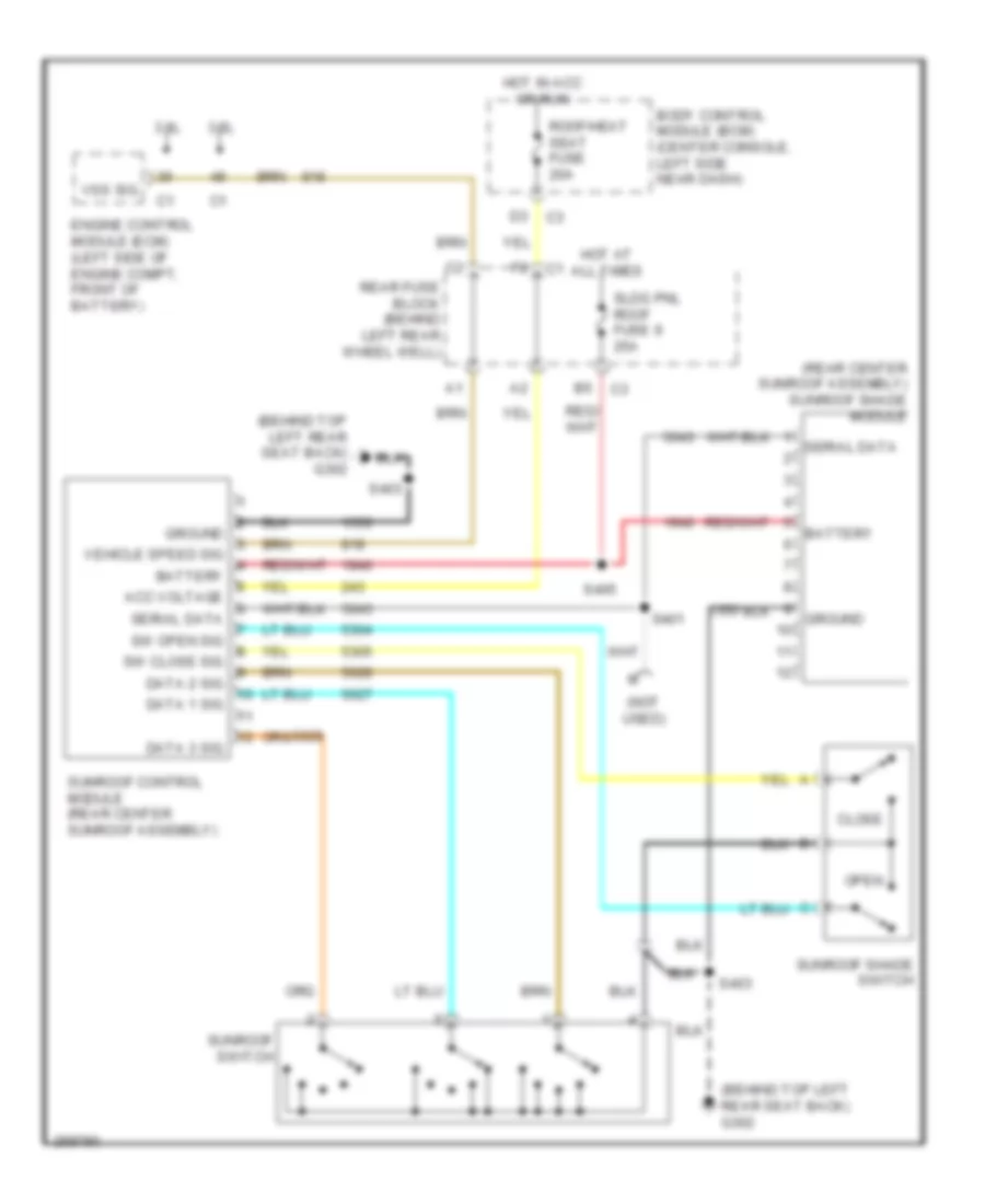
- (if equipped) sunroof control module
- (if equipped) traction control switch
- 2.4l hybrid
- Body control module (bcm)
- Center high mounted stop lamp (chmsl)
- Digital radio receiver
- Dome/ reading lamp
- Front courtesy/ reading lamps
- Fuel/pump relay
- G103 (left rear engine compt, top of strut tower)
- G110 (2.4l)
- G114
- G302 (behind top left rear seat back)
- G304 (behind right front kick panel)
- G305 (behind right front kick panel)
- G401 (rear luggage compt, below taillight)
- G403 (rear luggage compt, below taillight)
- Ignition coil/ module 1
- Ignition coil/ module 2
- Ignition coil/ module 3
- Ignition coil/ module 4
- Inflatable restraint front passenger presence system (pps) module
- Inflatable restraint sensing & diagnostic module (sdm)
- Inside rearview mirror
- Left back-up lamp
- Left front door courtesy lamp
- Left rear marker lamp
- Left rear turn signal lamp
- Left tail/ stop lamp
- Left vanity mirror lamp
- License lamp
- Nca
- Outside rearview window switch
- Power steering control module
- R/wdo defog relay
- Rear compartment lid latch
- Rear compartment lid release switch
- Rear fuse block (behind left rear wheel c1 well)
- Rear fuse block (behind left rear wheel well)
- Right back-up lamp
- Right rear marker lamp
- Right rear turn signal lamp
- Right tail/ stop lamp
- Right vanity mirror lamp
- S402
- S403
- S404
- S500
- Spot lamp
- Starter generator control module (sgcm)
- Sunroof control module
- Sunroof shade module
- Sunroof shade switch
- Sunroof switch
- W/ digital radio
- W/ onstar
- W/ panoramic roof
- W/ power variable effort
HEADLIGHTS
Headlights Wiring Diagram for Saturn Aura XR 2007
List of elements for Headlights Wiring Diagram for Saturn Aura XR 2007:
- (center of dash, near defrost deflector)
- A12
- Ambient light sensor
- Auto
- Automatic a/c
- B12
- Batt
- Body control module (bcm) (center console, left side near dash)
- C10
- Computer data lines system
- D10
- Drl fuse 46 15a
- Drl relay 46
- Drl rly ctrl
- F f
- F12
- Fog lamp switch
- Fog lmp rly ctrl
- Fog lmp sw sig
- Frt fog lp fuse 10 15a
- Frt fog relay 36
- Ftp
- Ftp sw sig
- G101 (left side of engine compt, near g109)
- G102 (behind right headlamp)
- G109 (left front engine compt, on core support)
- G201 (under dash, right side of console, near floor)
- G203 (under dash, right side of console, near floor)
- Hdlmps off
- Hdlmps on
- Head
- Headlamp dimmer sw hi beam sig
- Hi/ beam relay 35
- High
- High beam ind
- High beam rly ctrl
- Hot at all times
- Instrument panel cluster (ipc)
- Interior lights system
- Left front fog lamp
- Left high beam headlamp
- Left low beam headlamp
- Lo/ beam relay 38
- Logic
- Low
- Low beam rly ctrl
- Lt hi beam fuse 11 10a
- Lt low beam fuse 7 10a
- Lt sen low ref
- Lt sen sig
- Manual a/c
- Off
- On ind
- Park
- Right front fog lamp
- Right high beam headlamp
- Right low beam headlamp
- Rt hi beam fuse 12 10a
- Rt low beam fuse 9 10a
- S109
- S110
- Serial data
- Sunload sensor
- Turn signal/ multi-function switch
- Underhood fuse block (left side of engine compt, next to battery)
HORN
Horn Wiring Diagram for Saturn Aura XR 2007
List of elements for Horn Wiring Diagram for Saturn Aura XR 2007:
- (under dash, right side of console, near floor)
- B9 c2
- Body control module (bcm) (center console, left side near dash)
- C2 k
- C3 k
- E4 c3
- G101 (left side of engine compt, near g109)
- G201
- Ground distribution system
- Horn assembly (below left headlamp)
- Horn fuse 8 15a
- Horn relay
- Horn rly ctrl
- Horn switch
- Hot at all times
- Inflatable restraint steering wheel module coil (in steering column, behind steering wheel)
- Logic
- S201
- Tan
- Underhood fuse block (left side of engine compt, next to battery)
INSTRUMENT CLUSTER
Instrument Cluster Wiring Diagram (1 of 2) for Saturn Aura XR 2007
List of elements for Instrument Cluster Wiring Diagram (1 of 2) for Saturn Aura XR 2007:
- (bcm)
- (ebcm)
- (ecm)
- (rcdlr)
- (sdm)
- (under dash, right side of console, near floor) g201
- Abs ind
- Acc
- Air bag ind
- Anti-theft system
- Auto lights off, auto lights on, brake fluid, change oil soon, check gas cap, check tire press, cruise engaged, door ajar, eng pwr reduced, esc active, esc off, fuel range low, ice possible, key fob batt low, low fuel, low oil level, low traction, low washer fluid, oil life, push park pedal, service air bag, service esc, service traction, traction off & trunk ajar
- Batt
- Batt pos volt
- Body control module (bcm) (center console, left side near dash)
- Brake fluid level switch (under center brake fluid reservoir)
- Brake fluid lvl sens sig
- Brake ind
- Charging ind
- Chime
- Cluster/ theft fuse 10a
- Computer data lines system
- Coolant temperature gauge
- Cruise ind
- Dic display
- Driver information center (dic)
- Engine controls system
- Fuel level gauge
- G109 (left front engine compt, on core support)
- G201 (under dash, right side of console, near floor)
- Gnd
- Ground
- High beam ind
- High gmlan serial data -
- Hot at all times
- Ign
- Ign 1 volt
- Ignition (run/start)
- Ignition switch
- Illumination
- Inflatable restraint steering wheel module coil (in steering column, behind steering wheel)
- Info
- Instrument panel cluster (ipc)
- Km 000000
- Left steering wheel controls
- Left turn ind
- Lf dr ajar sw sig
- Logic
- Malfunction ind lamp
- Mil ctrl
- Off
- Oil level ind
- Park brake switch (under left side of dash, top of parking brake)
- Passenger dr ajar sw
- Pnk
- Power distribution system
- Pressure ind low tire
- Right turn ind
- Run
- S201
- Seat belt ind
- Security ind
- Security ind sig
- Select
- Ser data
- Serial data + high gmlan
- Serial data low gmlan
- Service vehicle soon ind
- Speedometer
- Start
- Sw sig lid ajar
- Sw sig park brake
- Tachometer
- Tan
- Temp ind engine coolant
- Traction off ind
- Traction on ind
Instrument Cluster Wiring Diagram (2 of 2) for Saturn Aura XR 2007
List of elements for Instrument Cluster Wiring Diagram (2 of 2) for Saturn Aura XR 2007:
- (3.5l) (bottom, left side of engine, on oil filter housing)
- (behind left rear wheel well) rear fuse block
- (center rear compartment lid) rear compartment lid latch
- (left side of engine, above starter)
- (rear of driver door) driver door latch assembly
- (rear of front passenger door) passenger door latch assembly
- (rear of left rear door) left rear door latch assembly
- (rear of right rear door) right rear door latch assembly
- 2.4l
- 3.5l
- 3.6l
- 5v ref 1
- Computer data lines system
- Engine control module (ecm) (2.4l: left side of engine compt, behind battery) (3.5l & 3.6l: left side of engine compt, front of battery)
- Engine oil level sensor (3.5l) (below oil pan)
- Engine oil pressure (eop) sensor
- Engine oil pressure (eop) switch
- Engine oil pressure (eop) switch (3.6l) (lower front, left side of engine)
- Fuel lvl sens sig
- Fuel pump & sender assembly (in fuel tank)
- G301 (behind top right rear seat back)
- G302 (behind top left rear seat back)
- Ground distribution system
- Low ref
- Oil level sw sig
- Oil pres sens sig
- Oil pressure sw
- Serial data +
- Serial data -
- Tan
INTERIOR LIGHTS
Courtesy Lamps Wiring Diagram for Saturn Aura XR 2007
List of elements for Courtesy Lamps Wiring Diagram for Saturn Aura XR 2007:
- (behind top right rear seat back) g301
- (not used)
- (rear of left rear door)
- (rear of right rear door)
- A10
- A5 c4
- Ajar
- Assembly (rear of driver door)
- Battery +
- Body control module (bcm) (center console, left side near dash)
- C1 e6
- Cargo lp diode 38
- Courtesy lamp
- Courtesy volt
- Ctsy lp ctrl
- D9 c1
- Dome lamp
- Dome/ reading lamp
- Door
- Door ajar
- Driver door latch ajar
- F2 c4
- F5 c3
- G301 (behind top right rear seat back)
- G302 (behind top left rear seat back)
- Hot at all times
- Interior lights fuse 10a
- Left door courtesy lamp
- Left reading lamp
- Left rear door latch assembly ajar
- Left rear reading lamp (if equipped)
- Left vanity mirror lamp
- Lf door ajar
- Logic
- Off
- Passenger door latch assembly (rear of front passenger door)
- Prk lamps fuse 6 10a
- Prk lp ctrl
- Prk lp relay 27
- Rear compartment courtesy lamp
- Rear compartment lid latch (center rear compartment lid)
- Rear fuse block (behind left rear wheel well)
- Rear lid ajar
- Right door courtesy lamp
- Right reading lamp
- Right rear door latch assembly ajar
- Right rear reading lamp (if equipped)
- Right vanity mirror lamp
- S500
- Spot lamp
- Sunroof
- W/ sunroof
- W/o
Instrument Illumination Wiring Diagram for Saturn Aura XR 2007
List of elements for Instrument Illumination Wiring Diagram for Saturn Aura XR 2007:
- Adjustable pedal position switch (if equipped)
- Auto
- B c1
- B1 c1
- B12
- Battery+
- Body control module (bcm) (center console, left side near dash)
- Bright
- C1 a12
- C11
- C12
- C2 k
- D1 c1
- D10
- Dim
- Dimmer sig
- Driver door lock switch
- Driver heated seat switch (if equipped)
- Driver window switch
- E11
- F11
- Fog lamp switch (if equi- pped)
- G201 (under dash, right side of console, near floor)
- G203 (under dash, right side of console, near floor)
- G301 (behind top right rear seat back)
- G302 (behind top left rear seat back)
- G303 (behind left front kick panel)
- G305 (behind right front kick panel)
- Gnd
- Hazard switch
- Hdlp sw sig
- Head
- Hot at all times
- Hvac control module (manual a/c)
- I/p dimmer switch
- Inflatable restraint steering wheel module coil (in steering column, behind steering wheel)
- Inst panel
- Interior lights fuse 10a
- Left steering wheel controls
- Logic
- Low ref
- Off
- Park
- Pass- enger door lock switch
- Pass- enger window switch
- Passenger heated seat switch (if equipped)
- Pk lp ctrl
- Pk lp volt
- Prk lamps fuse 6 10a
- Prk lp relay 27
- Radio
- Rear comp- artment lid release switch
- Rear fuse block (behind left rear wheel well)
- Rear seat audio (rsa) controller (if equipped)
- Red
- Right steering wheel controls
- S201
- S202
- S500
- Str/whl illum fuse 2a
- Traction control switch (if equipped)
- Trans- mission range indicator lamp
- Turn/ signal multi- function switch
POWER DISTRIBUTION
Power Distribution Wiring Diagram (1 of 5) for Saturn Aura XR 2007
List of elements for Power Distribution Wiring Diagram (1 of 5) for Saturn Aura XR 2007:
- (4 speed a/t)
- (6 speed a/t)
- (not used)
- (w/ front heated seats)
- 2.4l
- 3.5l/3.6l
- Abs fuse 24 60a
- Audio amp fuse 13 25a
- Audio amplifier
- B/u lp relay 33
- Batt
- Battery
- Bck/up lamps fuse 17 10a
- C3 d6
- Cig/aux fuse 20 20a
- Cigar lighter
- Console auxiliary power outlet
- Digital radio receiver (if equipped)
- Driver heated seat control module
- Drl fuse 46 15a
- Drl relay
- Ecm fuse 13 (2.4l/3.6l) 10a
- Electronic brake control module (ebcm)
- Engine control module (ecm)
- Eps fuse 41 80a
- From htd b seat fuse 14 (diagram 1 of 5)
- G303 (behind left front kick panel)
- Garage door opener (gdo) (if equipped)
- Generator
- Htd seat fuse 14 15a
- Passenger heated seat control module
- Power steering control module
- R/ wdo defog relay 26
- Rbec 1 fuse 22 60a
- Rear fuse block (behind left rear wheel well)
- Red
- Remote control door lock receiver (rcdlr)
- Rke/xm fuse 16 7.5a
- S/roof fuse 10 15a
- Starter generator control module (sgcm)
- Starter solenoid
- Sunroof control module (if equipped)
- Tcm fuse 42 10a
- To back-up lamps fuse 17 (diagram 1 of 5)
- To emission 2 fuse 5 (diagram 4 of 5)
- To ibcm 2 fuse 25 (diagram 2 of 5)
- Transmission control module (tcm)
- Underhood fuse block (left side of engine compt, next to battery)
Power Distribution Wiring Diagram (2 of 5) for Saturn Aura XR 2007
List of elements for Power Distribution Wiring Diagram (2 of 5) for Saturn Aura XR 2007:
- (w/ front heated seat)
- 2.4l
- A/c clu fuse 1 10a
- A/c clutch relay 34
- Accessory relay
- Battery sense fuse 54 5a
- Body control module (bcm) (center console, left side near dash)
- Cool fan 1 fuse 17 30a
- Cool/fan ser/par relay 29
- Cooling fan 1 relay 28
- Door lock fuse 15a
- Driver heated seat control module
- Driver heated seat switch
- Driver window switch
- From eps a fuse 41 (diagram 1 of 5)
- Ibcm 2 fuse 25 50a
- Inside rearview mirror (if equipped)
- Interior lights fuse 10a
- Logic
- Passenger heated seat control module
- Passenger heated seat switch
- Passenger window switch
- Power windows fuse 30a
- Pwr/trn relay 33
- Rear fuse block (behind left rear wheel well)
- Rly ctrl
- Roof/ heat seat fuse 10a
- S301
- Sunroof control module
- To ibcm 1 fuse 20 (diagram 3 of 5)
- To power mirrors fuse (diagram 4 of 5)
- Underhood fuse block (left side of engine compt, next to battery)
- W/ panoramic sunroof
- W/ standard sunroof
- Windshield wiper/ washer switch
- Wiper sw fuse 10a
Power Distribution Wiring Diagram (3 of 5) for Saturn Aura XR 2007
List of elements for Power Distribution Wiring Diagram (3 of 5) for Saturn Aura XR 2007:
- (not used)
- 5v ref
- Acc run
- Acc volt
- Air bag (batt) fuse 10a
- Body control module (bcm)
- Body control module (bcm) (center console, left side near dash)
- C1 (manual a/c)
- C2 (automatic a/c)
- Cluster/ theft fuse 10a
- Crank volt off/run/
- D11
- D12
- Data link connector (dlc)
- From cooling fan 1 fuse 17 (diagram 2 of 5)
- Hi/ beam relay 35
- Horn fuse 8 15a
- Horn relay
- Hvac control module
- Hvac ctrl (batt) fuse 10a
- Ibcm 1 fuse 20 30a
- Ign 1 volt
- Ign sensor fuse 2a
- Ignition switch
- Inflatable restraint sensing & diagnostic module (sdm)
- Instrument panel cluster (ipc)
- Key in ignition switch
- Lo/ beam relay 38
- Logic
- Off
- Pnk
- Radio
- Radio fuse 10a
- Start
- Theft deterrent control module
- To run rly fuse 19 (diagram 4 of 5)
- Underhood fuse block (left side of engine compt, next to battery)
Power Distribution Wiring Diagram (4 of 5) for Saturn Aura XR 2007
List of elements for Power Distribution Wiring Diagram (4 of 5) for Saturn Aura XR 2007:
- (automatic a/c)
- (behind left rear wheel well) rear fuse block
- (manual a/c)
- (not used)
- Adjustable pedal module (if equipped)
- Adjustable pedal position switch (if equipped)
- Blower motor control module
- Body control module (bcm) (center console, left side near dash)
- Cool fan 2 fuse 18 30a
- Cool/ fan 2 relay 30
- D10
- Driver seat adjuster switch
- Drv seat fuse 2 30a
- E10
- Emission 2 fuse 5 10a
- Evaporative emission (evap) canister vent solenoid valve
- From door d lock fuse (diagram 2 of 5)
- From horn fuse 8 e (diagram 3 of 5)
- From r/wdo defog relay 26 (diagram 1 of 5)
- Frt fog lp fuse 10 15a
- Frt fog relay
- Fuel pump fuse 25 15a
- Fuel/ pump relay
- Genrator battery assembly
- Genrator battery disconnect control module
- Hvac blower fuse (manual a/c) 20a
- Hvac blower high relay (manual a/c)
- Hvac control module
- Hvac ctrl (ign) fuse 10a
- Logic
- Onstar fuse 10a
- Outside rearview mirror switch
- Passenger seat adjuster switch (if equipped)
- Pedal fuse 10a
- Power mirrors fuse 2a
- Prk lamps fuse 6 10a
- Prk lp relay
- Psg seat fuse 1 30a
- Rbec 2 fuse 23 60a
- Red
- Rly ctrl
- Run relay
- Run rly fuse 19 30a
- S405
- Sldg pnl roof fuse 9 25a
- Stop lp fuse 47 10a
- Stop lp relay 49
- Sunroof control module
- Sunroof shade module
- To strtr fuse 26 (diagram 5 of 5)
- Trunk fuse 22 10a
- Trunk relay
- Underhood fuse block (left side of engine compt, next to battery)
- Vehicle communication interface module (vcim) (w/ onstar)
- W/ 2 way vertical driver power seat adjuster
- W/ 8 way front power seat adjuster
- Wpr 1 relay
- Wpr fuse 14 25a
Power Distribution Wiring Diagram (5 of 5) for Saturn Aura XR 2007
List of elements for Power Distribution Wiring Diagram (5 of 5) for Saturn Aura XR 2007:
- (2.4l)
- (2.4l) (3.6l)
- (3.5l) (2.4l)
- (3.6l)
- (4 speed a/t)
- (6 speed a/t)
- (left side of engine compt, next to battery) underhood fuse block
- (not used)
- 1-2 shift solenoid (1-2 ss) valve
- 2-3 shift solenoid (2-3 ss) valve
- 2.4l
- 3.5l
- 3.6l
- 4 speed a/t
- 4 speed a/t fwd w/ hybrid
- 4-3 shift solenoid (4-3 ss) valve
- Abs fuse 15 10a
- Air bag (ign) fuse 10a
- Automatic transmission
- B10
- Bas pmp maf fuse 5 20a 10a
- Body control module
- Body control module (bcm) (center console, left side near dash)
- C10
- C2 f6
- Ecm ign 1 fuse 16 10a
- Electronic brake control module (ebcm)
- Energy storage control module (escm)
- Engine control module (ecm)
- Engine control module (ecm) (2.4l/3.6l)
- Eps fuse 2a
- From wpr fuse 14 (diagram 4 of 5)
- G109 (left front engine compt, on core support)
- Generator battery assembly
- Generator battery disconnect control module
- Heater coolant pump
- Ibcm (run/crank) fuse 21 30a
- If equipped
- Ign 1 ecm ign 1 bas ign fuse 3 15a 10a
- Inflatable restraint front passenger presence system (pps) module
- Inflatable restraint passenger air bag on/off indicator
- Inflatable restraint sensing & diagnostic module (sdm)
- Inflatable restraint steering wheel module coil
- Left steering wheel controls
- Left top up/ top down switch
- Mass air flow (maf)/ intake air temperature (iat) sensor
- Pnk
- Power steering control module (if equipped)
- R/c rly coil ctrl
- Red
- Run/ crank fuse 2a
- Run/ crank relay 32
- S103
- S209
- Start relay 31
- Starter generator control module (sgcm)
- Starter generator control module (sgcm) cooling pump
- Strtr fuse 26 30a
- Torque converter clutch pulse width modulation (tcc pwm) solenoid valve
- Trans fuse 4 10a
- Transmission control module (tcm)
POWER DOOR LOCKS
Power Door Locks Wiring Diagram for Saturn Aura XR 2007
List of elements for Power Door Locks Wiring Diagram for Saturn Aura XR 2007:
- (center console, left side near dash) body control module (bcm)
- Ajar
- Ajar switch pass dr
- Antenna
- Cntrl act unlock door lock
- Computer data lines system
- Door lock
- Door lock act lock cntrl
- Door lock fuse 15a
- Driver door latch assembly (rear of driver door)
- Driver door lock switch
- Drv dr ajar switch signal
- G301 (behind top right rear seat back)
- Ground
- Hot at all times
- Instrument panel cluster (ipc)
- Interior lights system
- Left rear door latch assembly (rear of left rear door)
- Lock
- Logic
- Low spd gmlan
- Nca
- Passenger door latch assembly (rear of front passenger door)
- Passenger door lock switch
- Power distribution system
- Radio
- Rear fuse block (behind left rear wheel well)
- Remote control door lock receiver (rcdlr) (center of rear window shelf)
- Right rear door latch assembly (rear of right rear door)
- Rke/xm fuse 16 7.5a
- Serial
- Serial data
- Serial data c1
- Serial data gmlan low spd
- Signal
- Signal key switch drv dr
- Signal lck/unlck
- Tan
- Trunk rel relay control
- Trunk, tailgate, fuel doors system
- Unlk cntrl lock act drv dr
- Unlock
- Vehicle communications data interface module (vcim) (right side of c3 dash, above kick panel)
- W/ vehicle communications
- W/o driver door unlock relay
- W/o vehicle communi- cations
POWER MIRRORS
Electrochromic Mirror Wiring Diagram for Saturn Aura XR 2007
List of elements for Electrochromic Mirror Wiring Diagram for Saturn Aura XR 2007:
- Ambient light sensor (windshield side)
- Body control module (bcm) (center console, left side near dash)
- Button back- lighting
- Emergency
- Emergency ind
- Exterior lights system
- G305 (behind right front kick panel)
- Ground
- Headlight sensor (mirror side)
- High sensitivity setting
- Hot in acc or run
- Inside rearview mirror
- Keypad green led ind
- Keypad green led sig
- Keypad red led ind
- Keypad red led sig
- Keypad signal
- Logic
- Low sensitivity setting
- Max
- Min
- Off
- Onstar
- Onstar ind
- Onstar keypad
- Phone
- Phone ind
- Power distribution system
- Rear fuse block (behind left rear wheel well)
- Reflectivity in reverse
- Resets to daytime high
- Roof/heat seat fuse 10a
- Vehicle communication interface module (vcim) (right side of dash, above kick panel)
Power Mirrors Wiring Diagram for Saturn Aura XR 2007
List of elements for Power Mirrors Wiring Diagram for Saturn Aura XR 2007:
- Body control module (bcm) (center console, left side near dash)
- Defogger system
- Down
- Driver outside rearview mirror
- Driver/ passenger select switch
- G302 (behind top left rear seat back)
- Hot at all times
- Left
- Left/ right
- Nca
- Outside rearview mirror switch
- Passenger outside rearview mirror
- Power mirrors fuse 2a
- Right
- Up/ down
POWER SEATS
2-Way Adjustable Power Seat Wiring Diagram for Saturn Aura XR 2007
List of elements for 2-Way Adjustable Power Seat Wiring Diagram for Saturn Aura XR 2007:
- Down
- Driver seat adjuster switch (2-way)
- Driver seat vertical motor (under driver seat)
- Drv seat fuse 2 30a
- G303 (behind left front kick panel)
- Hot at all times
- Rear fuse block (behind left rear wheel well)
- S302
8-Way Adjustable Power Seat Wiring Diagram for Saturn Aura XR 2007
List of elements for 8-Way Adjustable Power Seat Wiring Diagram for Saturn Aura XR 2007:
- Driver seat adjuster switch (8-way)
- Driver seat front vertical motor (under driver seat)
- Driver seat horizontal motor (under driver seat)
- Driver seat rear vertical motor (driver seat back)
- Driver seat recline motor (driver seat back)
- Drv seat fuse 2 30a
- Front down
- Front up
- Fwd
- G303 (behind left front kick panel)
- Hot at all times
- Rear down
- Rear fuse block (behind left rear wheel well)
- Rear up
- Rwd
- Tan
Adjustable Pedal Wiring Diagram for Saturn Aura XR 2007
List of elements for Adjustable Pedal Wiring Diagram for Saturn Aura XR 2007:
- 5v ref
- Adj pedal inhibit sw
- Adjustable pedal actuator
- Adjustable pedal module (under left side of dash, left of brake pedal)
- Adjustable pedal position sensor (pedal chassis, above brake pedal)
- Adjustable pedal position switch
- Battery
- Body control module (bcm) (center console, left side near dash)
- D10
- Enable sig
- Fwd
- G201 (under dash, right side of console, near floor)
- G203 (under dash, right side of console, near floor)
- Gnd
- Hot at all times
- Illum
- Inhibit sig
- Interior lights system
- Logic
- Low ref
- Pedal fuse 10a
- Pnk
- Rwd
- Sens sig
Heated Seats Wiring Diagram for Saturn Aura XR 2007
List of elements for Heated Seats Wiring Diagram for Saturn Aura XR 2007:
- (behind left front kick panel) g303
- Accy vol
- B12
- Battery
- Body control module (bcm) (center console, left side near dash)
- C1 element ctrl
- C1 f11
- D10
- Driver heated seat back element (driver seat back)
- Driver heated seat control module (under driver seat)
- Driver heated seat cushion element (driver seat bottom)
- Driver heated seat cushion temperature sensor
- Driver heated seat switch
- Front passenger heated seat back element (passenger seat back)
- Front passenger heated seat cushion element (in front passenger seat bottom)
- Ground
- Heated seat sw sig
- High
- Hot at all times
- Hot in run or acc
- Htd seat fuse 14 15a
- Inflatable restraint passenger presence system (pps) module (front passenger seat cushion)
- Instrument panel lamp sply volt
- Logic
- Low
- Low ref
- Passenger heated seat control module (under front passenger seat)
- Passenger heated seat cushion temperature sensor
- Passenger heated seat switch
- Rear fuse block (behind left rear wheel well)
- Red
- Roof/ heat seat fuse 10a
- S301
- S305
- Seat back
- Seat back element ctrl
- Seat back element vol
- Seat cushion element ctrl
- Seat cushion element vol
- Seat cushion temp sen sig
Passenger Power Seat Wiring Diagram for Saturn Aura XR 2007
List of elements for Passenger Power Seat Wiring Diagram for Saturn Aura XR 2007:
- Front down
- Front up
- Fwd
- G301 (behind top right rear seat back)
- Hot at all times
- Passenger seat adjuster switch
- Passenger seat front vertical motor (under front passenger seat)
- Passenger seat horizontal motor (under front passenger seat)
- Passenger seat rear vertical motor (under front passenger seat)
- Psg seat fuse 1 30a
- Rear down
- Rear fuse block (behind left rear wheel well)
- Rear up
- Rwd
- Tan
POWER TOP/SUNROOF
Panoramic Roof Wiring Diagram for Saturn Aura XR 2007
List of elements for Panoramic Roof Wiring Diagram for Saturn Aura XR 2007:
- (behind top left rear seat back) g302
- (not used)
- (rear center sunroof assembly) sunroof shade module
- 3.5l
- 3.6l
- Acc voltage
- Battery
- Body control module (bcm) (center console, left side near dash)
- Close
- Data 1 sig
- Data 2 sig
- Data 3 sig
- Engine control module (ecm) (left side of engine compt, front of battery)
- Ground
- Hot at all times
- Hot in acc or run
- Open
- Rear fuse block (behind left rear wheel well)
- Roof/heat seat fuse 20a
- S401
- S403
- S405
- Serial data
- Sldg pnl roof fuse 9 25a
- Sunroof control module (rear center sunroof assembly)
- Sunroof shade switch
- Sunroof switch
- Sw close sig
- Sw open sig
- Vehicle speed sig
- Vss sig
Sunroof Wiring Diagram for Saturn Aura XR 2007
List of elements for Sunroof Wiring Diagram for Saturn Aura XR 2007:
- (rear center sunroof assembly)
- Acc volt
- Batt pos volt
- Body control module (bcm) (center console, left side near dash)
- Close
- Close sig
- G302 (behind top left rear seat back)
- Gnd
- Hot at all times
- Hot in acc or run
- Low ref
- Open
- Open sig
- Power distribution system
- Rear fuse block (behind left rear wheel well)
- Roof/heat seat fuse 10a
- S/roof fuse 10 15a
- Sunroof control module
- Sunroof switch
POWER WINDOWS
Power Windows Wiring Diagram for Saturn Aura XR 2007
List of elements for Power Windows Wiring Diagram for Saturn Aura XR 2007:
- A11
- B11
- Body control module (bcm) (center console, left side near dash)
- C11
- Down
- Driver
- Driver window motor (center of driver door)
- Driver window switch
- Express down
- Express logic
- Express up
- G303 (behind left front kick panel)
- Ground
- Hot w/ accessory relay energized
- Illumination lamp
- Interior lights system
- Left rear
- Left rear window motor (center left rear door)
- Left rear window switch
- Lock out switch
- Logic
- Passenger
- Passenger window motor (center of passenger door)
- Passenger window switch
- Power distribution system
- Power window driver fuse 20a
- Power windows fuse 30a
- Pwr window mtr left front down ctrl
- Pwr window mtr left front up ctrl
- Right rear
- Right rear window motor (center right rear door)
- Right rear window switch
- Roof/heat seat fuse 10a
- Tan
- Voltage accessory
- Voltage battery positive
RADIO
Radio Wiring Diagram, Base for Saturn Aura XR 2007
List of elements for Radio Wiring Diagram, Base for Saturn Aura XR 2007:
- 10 volt ref
- Antenna 12v sw sply volt
- Antenna amplifier module
- Antenna sig
- Audio common
- B tan
- Bare
- Battery pos volt
- Body control module (bcm) (center console, left side near dash)
- C c3
- C2 c
- Case ground
- Computer data lines system
- Drain wire
- G201 (under dash, right side of console, near floor)
- Ground
- Hot at all times
- Inflatable restraint steering wheel module coil (in steering column, behind steering wheel)
- Instrument panel lamp sply
- Interior lights system
- Left audio sig (+)
- Left front door speaker
- Left front tweeter speaker
- Left rear speaker
- Lf speaker (+)
- Lf speaker (-)
- Logic
- Low ref
- Low spd gmlan ser data
- Lr speaker output (+)
- Lr speaker output (-)
- Mute
- Nca
- Pnk
- Radio
- Radio antenna
- Radio fuse 10a
- Rear window antenna module
- Rf speaker (+)
- Rf speaker (-)
- Right audio sig (+)
- Right front door speaker
- Right front tweeter speaker
- Right rear speaker
- Right steering wheel controls
- Rr speaker output (+)
- Rr speaker output (-)
- Satellite radio circuit
- Seek dn
- Seek up
- Shield
- Steering wheel ctrl sig
- Tan
- Vehicle communication interface module (vcim) (right side of dash, above kick panel)
- Voice sig
- Vol dn -
- Vol up +
Radio Wiring Diagram, Enhanced (1 of 2) for Saturn Aura XR 2007
List of elements for Radio Wiring Diagram, Enhanced (1 of 2) for Saturn Aura XR 2007:
- 10 volt ref
- Amplifier mute
- Antenna 12v sw sply volt
- Antenna amplifier module
- Antenna sig
- Audio common
- Bare
- Battery pos volt
- Body control module (bcm) (center console, left side near dash)
- C2 c
- C3 c
- Case ground
- Computer data lines system
- Drain wire
- G201 (under dash, right side of console, near floor)
- Ground
- Hot at all times
- Inflatable restraint steering wheel module coil (in steering column, behind steering wheel)
- Instrument panel lamp sply
- Interior lights system
- Jacks radio control
- Left audio sig (+)
- Lf low lvl audio sig (+)
- Lf low lvl audio sig (-)
- Logic
- Low ref
- Low spd gmlan ser data
- Lr low lvl audio sig (+)
- Lr low lvl audio sig (-)
- Mute
- Nca
- Pnk
- Radio
- Radio antenna
- Radio fuse 10a
- Rear seat audio sig
- Rear window antenna module
- Remote radio ctrl sig
- Rf low lvl audio sig (+)
- Rf low lvl audio sig (-)
- Right audio sig (+)
- Right steering wheel controls
- Rr low lvl audio sig (+)
- Rr low lvl audio sig (-)
- Satellite radio circuit
- Seek dn
- Seek up
- Shield
- Steering wheel ctrl sig
- Tan
- Vehicle communication interface module (vcim) (right side of dash, above kick panel)
- Voice sig
- Vol dn -
- Vol up +
- W/ rear seat & earphone
- W/o rear seat & earphone
Radio Wiring Diagram, Enhanced (2 of 2) for Saturn Aura XR 2007
List of elements for Radio Wiring Diagram, Enhanced (2 of 2) for Saturn Aura XR 2007:
- (behind right front kick panel) g305
- 10 volt ref
- Amplifier enable
- Amplifier mute
- Audio amp fuse 13 25a
- Audio amplifier (rear compt, below right taillight)
- Battery pos volt
- Exterior lights system
- G301 (behind top right rear seat back)
- Ground
- Hot at all times
- Instrument panel sply
- Interior lights system
- Left front door speaker
- Left front speaker
- Left rear speaker
- Lf low lvl audio sig (+)
- Lf low lvl audio sig (-)
- Lf speaker out (+)
- Lf speaker out (-)
- Lr low lvl audio sig (+)
- Lr low lvl audio sig (-)
- Lr speaker out (+)
- Lr speaker out (-)
- Lr sub spkr out (+)
- Lr sub spkr out (-)
- Nca
- Park lamps sply volt
- Pnk
- Rear fuse block (behind left rear wheel well)
- Rear seat audio (rsa) controller (w/ rear seat & earphone jacks radio control)
- Rear seat audio sig
- Remote radio ctrl sig
- Rf low lvl audio sig (+)
- Rf low lvl audio sig (-)
- Rf speaker out (+)
- Rf speaker out (-)
- Right front door speaker
- Right front speaker
- Right rear speaker
- Rr low lvl audio sig (+)
- Rr low lvl audio sig (-)
- Rr speaker out (+)
- Rr speaker out (-)
- Rr sub spkr out (+)
- Rr sub spkr out (-)
- Subwoofer
- Tan
- Tweeter
Satellite Radio Wiring Diagram for Saturn Aura XR 2007
List of elements for Satellite Radio Wiring Diagram for Saturn Aura XR 2007:
- (behind right front kick panel) g305
- (right side of dash, above kick panel) vehicle communication interface module (vcim)
- Antenna ground
- Antenna sig
- Audio common
- Bare
- Battery pos volt
- Cell phone voice sig
- Computer data lines system
- Digital radio antenna
- Digital radio receiver (under rear shelf)
- Drain wire
- Gmlan ser data
- Ground
- Hot at all times
- Low ref
- Lt audio sig (+)
- Power distribution system
- Radio
- Rear fuse block (behind left rear wheel well)
- Rke/xm fuse 16 7.5a
- Rt audio sig (+)
- Voice sig
SHIFT INTERLOCK
Shift Interlock Wiring Diagram for Saturn Aura XR 2007
List of elements for Shift Interlock Wiring Diagram for Saturn Aura XR 2007:
- 5 volt reference
- A/t shift lock control solenoid (in shifter assembly)
- Battery
- Body control module (bcm) (center console, left side near dash)
- Brake pedal position sensor (right side of brake pedal bracket)
- Brake pedal position sensor signal
- Door lock fuse 15a
- G303 (behind left front kick panel)
- G305 (behind right front kick panel)
- Ground
- Hot at all times
- Interior lights fuse 10a
- Interior lights system
- Logic
- Low reference
- Red
STARTING/CHARGING
2.4L VIN 5
2.4L VIN 5, Hybrid Wiring Diagram (1 of 2) for Saturn Aura XR 2007
List of elements for 2.4L VIN 5, Hybrid Wiring Diagram (1 of 2) for Saturn Aura XR 2007:
- (not used)
- 12v
- 36-volt
- 36v
- Bas batt fuse 10a
- Bas ign fuse 10a
- Battery
- Battery pos
- Computer data lines system
- Coolant pump
- Cooling fans system
- Drain wire
- Emission 2 fuse 10a
- Fuse 175a
- G114
- Gnd
- Ground
- Hi serial bus +
- Hi serial bus -
- Hot at all times
- Hot in run or start
- Ign 1 ecm ign bas ign fuse 10a
- Ign 1 volt
- Logic
- Loop sig
- Low ref
- Motor +
- Motor -
- Motor positive
- Nca
- Pnk
- Power distribution system
- Pump ctrl
- Pump mtr vol
- Pump rly coil
- Rear fuse block (behind left rear wheel well)
- Red
- S101
- S102
- S103
- S105
- Shield
- Sig 1
- Sig 2
- Sig 3
- Sig 4
- Starter generator (lower left, front of engine)
- Starter generator control module (sgcm) (left front engine compt)
- Stud u
- Stud v
- Stud w
- Tan
- Temperature sig
- Trans pump drv
- Underhood fuse block (left side of engine compt, next to battery)
- Water pump sply
2.4L VIN 5, Hybrid Wiring Diagram (2 of 2) for Saturn Aura XR 2007
List of elements for 2.4L VIN 5, Hybrid Wiring Diagram (2 of 2) for Saturn Aura XR 2007:
- 200a
- 36-volt
- Battery current sensor
- Battery disconnect switch
- Battery pos voltage
- Computer data lines system
- Cooling fans system
- Fan ctrl
- Fan tach feedback
- G301 (behind top right rear seat back)
- G402
- Generator 1a ctrl
- Generator 1b ctrl
- Generator 2a ctrl
- Generator 2b ctrl
- Generator 3a ctrl
- Generator 3b ctrl
- Generator battery 1
- Generator battery 2
- Generator battery 3
- Generator battery assembly
- Generator battery disconnect control module
- Generator battery fuse
- Gnd
- High speed gmlan bus+
- High speed gmlan bus-
- Ign 1 volt
- J4xx
- Low ref
- Main contactor relay
- Nca
- Pnk
- Power
- Red
- Shield
- Tan
2.4L VIN 5, Starting Wiring Diagram for Saturn Aura XR 2007
List of elements for 2.4L VIN 5, Starting Wiring Diagram for Saturn Aura XR 2007:
- (center console, left side near dash)
- (left side of engine compt, next to battery)
- 5-volt ref
- Acc
- Battery
- Battery current sensor
- Body control module (bcm)
- C1 c2
- C10
- Computer data lines system
- Current sens isg
- Current sensor sig
- D1 c4
- D12 c1
- Door lock/ unlock sig
- Door locks system
- Ecm ign 1 fuse 10a
- Engine control module (ecm) (left side of engine compt, behind battery)
- Exterior lights system
- G104 (left side of engine compt, on core support)
- G105 (under left intake manifold, on rear of cylinder head)
- G109 (left front engine compt, on core support)
- Hazard switch sig
- High speed gmlan serial data bus +
- High speed gmlan serial data bus -
- Hot at all times
- Ign 1
- Ign sensor fuse 2a
- Ignition 1
- Ignition switch
- Key in ignition switch
- Logic
- Low ref
- Off
- Off/run crank voltage 5v ref
- Park/neutral position (pnp) switch (on transmission, below master cylinder)
- Park/neutral sig
- Pnk
- Power distribution system
- Red
- Run
- Run/crank relay
- Run/crank relay coil control
- Start
- Start relay
- Starter rly coil ctrl
- Starter solenoid
- Strtr fuse 30a
- Tan
- Underhood fuse block
3.5L VIN N
3.5L VIN N, Charging Wiring Diagram for Saturn Aura XR 2007
List of elements for 3.5L VIN N, Charging Wiring Diagram for Saturn Aura XR 2007:
- (not used)
- 3.5l
- 3.6l
- B+ s
- Battery
- Battery position voltage
- Body control module (bcm) (center console, left side near dash)
- Charge ind
- Cluster/ theft fuse 10a
- Computer data lines system
- Engine control module (ecm) (left side of engine compt, front of battery)
- F1 c4
- G104 (left side of engine compt, on core support)
- G105 (under left intake manifold, on rear of cylinder head)
- Generator
- Generator field duty cycle signal
- Generator turn on signal
- High speed gmlan serial data bus +
- High speed gmlan serial data bus -
- Hot at all times
- Ign
- Instrument panel cluster (ipc)
- Logic
- Low speed gmlan serial data
- Power distribution system
- Red
- Serial data
- Starter solenoid
- Tan
3.5L VIN N, Starting Wiring Diagram for Saturn Aura XR 2007
List of elements for 3.5L VIN N, Starting Wiring Diagram for Saturn Aura XR 2007:
- (3.5l)
- (3.6l)
- (center console, left side near dash)
- (left side of engine compt, next to battery)
- 3.5l
- 3.6l
- 5v ref
- A3 c2
- Acc
- Anti-theft system
- Battery
- Body control module (bcm)
- C1 d8
- C10
- C2 f6
- Charging circuit
- Computer data lines system
- D1 c4
- D12 c1
- Door locks system
- Door/lock/ unlock signal
- E12 c1
- Ecm ign 1 fuse 10a
- Engine control module (ecm) (left side of engine compt, front of battery)
- Exterior lights system
- G104 (left side of engine compt, on core support)
- G105 (under left intake manifold, on rear of cylinder head)
- G109 (left front engine compt, on core support)
- Hazard switch signal
- High speed gmlan serial data bus +
- High speed gmlan serial data bus -
- Hood ajar switch signal
- Hot at all times
- Ign 1
- Ign sensor fuse 2a
- Ignition 1
- Ignition switch
- Key in ignition switch
- Logic
- Off
- Off/run crank voltage
- Park/neutral position (pnp) switch (on transmission, below master cylinder)
- Park/neutral signal
- Pnk
- Power distribution system
- Red
- Run
- Run/crank relay
- Run/crank relay coil control
- Start
- Start relay
- Starter rly coil ctrl
- Starter solenoid
- Strtr fuse 30a
- Tan
- Transmission control module (tcm) (inboard side, left front frame rail extension)
- Underhood fuse block
3.6L VIN 7
3.6L VIN 7, Charging Wiring Diagram for Saturn Aura XR 2007
List of elements for 3.6L VIN 7, Charging Wiring Diagram for Saturn Aura XR 2007:
- (not used)
- 3.5l
- 3.6l
- B+ s
- Battery
- Battery position voltage
- Body control module (bcm) (center console, left side near dash)
- Charge ind
- Cluster/ theft fuse 10a
- Computer data lines system
- Engine control module (ecm) (left side of engine compt, front of battery)
- F1 c4
- G104 (left side of engine compt, on core support)
- G105 (under left intake manifold, on rear of cylinder head)
- Generator
- Generator field duty cycle signal
- Generator turn on signal
- High speed gmlan serial data bus +
- High speed gmlan serial data bus -
- Hot at all times
- Ign
- Instrument panel cluster (ipc)
- Logic
- Low speed gmlan serial data
- Power distribution system
- Red
- Serial data
- Starter solenoid
- Tan
3.6L VIN 7, Starting Wiring Diagram for Saturn Aura XR 2007
List of elements for 3.6L VIN 7, Starting Wiring Diagram for Saturn Aura XR 2007:
- (3.5l)
- (3.6l)
- (center console, left side near dash)
- (left side of engine compt, next to battery)
- 3.5l
- 3.6l
- 5v ref
- A3 c2
- Acc
- Anti-theft system
- Battery
- Body control module (bcm)
- C1 d8
- C10
- C2 f6
- Charging circuit
- Computer data lines system
- D1 c4
- D12 c1
- Door locks system
- Door/lock/ unlock signal
- E12 c1
- Ecm ign 1 fuse 10a
- Engine control module (ecm) (left side of engine compt, front of battery)
- Exterior lights system
- G104 (left side of engine compt, on core support)
- G105 (under left intake manifold, on rear of cylinder head)
- G109 (left front engine compt, on core support)
- Hazard switch signal
- High speed gmlan serial data bus +
- High speed gmlan serial data bus -
- Hood ajar switch signal
- Hot at all times
- Ign 1
- Ign sensor fuse 2a
- Ignition 1
- Ignition switch
- Key in ignition switch
- Logic
- Off
- Off/run crank voltage
- Park/neutral position (pnp) switch (on transmission, below master cylinder)
- Park/neutral signal
- Pnk
- Power distribution system
- Red
- Run
- Run/crank relay
- Run/crank relay coil control
- Start
- Start relay
- Starter rly coil ctrl
- Starter solenoid
- Strtr fuse 30a
- Tan
- Transmission control module (tcm) (inboard side, left front frame rail extension)
- Underhood fuse block
SUPPLEMENTAL RESTRAINTS
Supplemental Restraints Wiring Diagram (1 of 3) for Saturn Aura XR 2007
List of elements for Supplemental Restraints Wiring Diagram (1 of 3) for Saturn Aura XR 2007:
- (behind right front kick panel) g304
- Airbag (batt) fuse 10a
- Airbag (ign) fuse 10a
- Batt positive volt
- Body control module (bcm) (in center console, left side near dash)
- Case ground
- Computer data lines system
- D11
- Ground
- High control
- Hot at all times
- Hot in run or start
- Ignition 1
- Inflatable restraint sensing & diagnostic module (sdm) (under center console)
- L seat belt sw sig
- Left front inflatable restraint seat belt pretensioner (if equipped) (in base of left "b" pillar)
- Left inflatable restraint front end sensor (in front of left side of radiator)
- Left inflatable restraint side impact sensor (sis) (in lower center of driver's door)
- Left seat belt switch
- Low control
- Low ref
- Nca
- Pnk
- Pps signal
- R seat belt sw sig
- Right front inflatable restraint seat belt pretensioner (if equipped) (in base of right "b" pillar)
- Right inflatable restraint front end sensor (in front of right side of radiator)
- Right inflatable restraint side impact sensor (sis) (in lower center of passenger's door)
- Right seat belt switch
- Serial data
- Shorting bar
- Signal
- Tan
- Voltage
Supplemental Restraints Wiring Diagram (2 of 3) for Saturn Aura XR 2007
List of elements for Supplemental Restraints Wiring Diagram (2 of 3) for Saturn Aura XR 2007:
- (sdm)
- A c1
- Air bag indicator
- B c2
- Batt
- Body control module (bcm) (in center console, left side near dash)
- Computer data lines system
- Hot in run or start
- Ign
- Ind
- Inflatable restraint i/p module (right side of dash)
- Inflatable restraint steering wheel module (in center of steering wheel)
- Inflatable restraint steering wheel module coil (behind steering wheel, in steering column)
- Instrument panel cluster
- Left front inflatable restraint side impact module (driver's seat back)
- Logic
- Nca
- Pnk
- Right front inflatable restraint side impact module (front passenger's seat back)
- Run/ crank fuse 2a
- Seat belt indicator
- Serial data
- Shorting bar
- Stage 1
- Stage 2
- Tan
- Vehicle communication interface module (right side of dash, above kick panel)
- W/ vehicle communications
- W/o vehicle communications
Supplemental Restraints Wiring Diagram (3 of 3) for Saturn Aura XR 2007
List of elements for Supplemental Restraints Wiring Diagram (3 of 3) for Saturn Aura XR 2007:
- B10
- Battery b+
- Case ground
- Front passenger mass & position signal
- G203 (under dash, right side of console, near floor
- G304 (behind right front kick panel)
- Ground
- Heated seat ref
- Humidity sensor
- Ignition 1
- Ignition 1 voltage
- Illumination
- Inflatable restraint front passenger presence system (pps) module (inside front) passenger seat cushion)
- Inflatable restraint front passenger presence system (pps) sensor (front passenger seat cushion)
- Inflatable restraint passenger air bag on/off indicator
- Left inflatable restraint roof rail module (under headliner, above left doors)
- Nca
- Off ind
- On ind
- Pass air bag off ind
- Pass air bag on ind
- Pass seat belt ind
- Pnk
- Power ind
- Power seats system
- Pps signal
- Red
- Right inflatable restraint roof rail module (under headliner, above right doors)
- Shorting bar
- Temp sensor
TRANSMISSION
2.4L VIN 5
2.4L VIN 5, A/T Wiring Diagram (1 of 2) for Saturn Aura XR 2007
List of elements for 2.4L VIN 5, A/T Wiring Diagram (1 of 2) for Saturn Aura XR 2007:
- 1-2 shift sol vlv ctrl
- 2-3 shift sol vlv ctrl
- 4-3 shift sol vlv ctrl
- Acc voltage
- Battery
- Computer data lines system
- Engine control module (ecm) (left side of engine compt, behind battery)
- Exterior lights system
- Fluid pressure transmission
- G107
- Gmlan data +
- Gmlan data -
- Ground
- Hi ctrl
- Hi sig
- Ign 1
- Low ctrl
- Low ref
- Low sig
- Park/neutral position (pnp) switch (on transmission, below master cylinder)
- Pnk
- Stop lamp
- Sw sig a
- Sw sig b
- Sw sig c
- Sw sig p
- Tan
- Tcc pwm sol vlv ctrl
- Tcc rel sw sig
- Tft sens sig
- Transmission control module (tcm) (left side of engine compt, right of battery)
- Vehicle speed sensor (vss) (on transmission, at front, rear side of engine)
- Vss hi sig
- Vss lo sig
2.4L VIN 5, A/T Wiring Diagram (2 of 2) for Saturn Aura XR 2007
List of elements for 2.4L VIN 5, A/T Wiring Diagram (2 of 2) for Saturn Aura XR 2007:
- (left front engine compt, on core support) g109
- 1-2 shift solenoid (1-2 ss) valve
- 2-3 shift solenoid (2-3 ss) valve
- 4-3 shift solenoid (4-3 ss) valve
- Acc
- Acc voltage
- Automatic transmission
- Automatic transmission fluid pressure (tfp) manual valve position switch
- Automatic transmission fluid temperature (tft) sensor
- Automatic transmission input shaft speed (at iss) sensor
- Body control module (bcm) (center console, left side near dash)
- C10
- Computer data lines system
- Dr switch
- Gmlan data +
- Gmlan data -
- Hot at all times
- Ignition switch
- Lock
- Logic
- Pnk
- Power distribution system
- Pressure control (pc) solenoid valve
- Red
- Red a
- Rev switch
- Rly coil ctrl
- Run
- Run/ crank relay 32
- S103
- Start
- Tan
- Tcc release switch
- Tcm fuse 10a
- Torque converter clutch pulse width modulation (tcc pwm) solenoid valve
- Trans fuse 4 10a
- Underhood fuse block (left side of engine compt, next to battery)
3.5L VIN N
3.5L VIN N, A/T Wiring Diagram (1 of 2) for Saturn Aura XR 2007
List of elements for 3.5L VIN N, A/T Wiring Diagram (1 of 2) for Saturn Aura XR 2007:
- 1-2 shift sol vlv ctrl
- 2-3 shift sol vlv ctrl
- Acc voltage
- Battery
- Computer data lines system
- E (not used) c103
- Exterior lights system
- G107
- Gmlan data +
- Gmlan data -
- Ground
- Hi ctrl
- Hi sig
- Ign 1
- Low ctrl
- Low ref
- Low sig
- Park/neutral position (pnp) switch (on transmission, below master cylinder)
- Pnk
- Stop lamp
- Sw sig a
- Sw sig b
- Sw sig c
- Sw sig p
- Tan
- Tap up/tap down sw sig
- Tcc pwm sol vlv ctrl
- Tcc rel sw sig
- Tft sens sig
- Transmission control module (tcm) (inboard side, left front frame rail extension)
- Vehicle speed sensor (vss) (on transmission, at front, rear side of engine)
- Vss hi sig
- Vss lo sig
3.5L VIN N, A/T Wiring Diagram (2 of 2) for Saturn Aura XR 2007
List of elements for 3.5L VIN N, A/T Wiring Diagram (2 of 2) for Saturn Aura XR 2007:
- (left front engine compt, on core support) g109
- 1-2 shift solenoid (1-2 ss) valve
- 2-3 shift solenoid (2-3 ss) valve
- Acc
- Acc voltage
- Automatic transmission
- Automatic transmission fluid pressure (tfp) manual valve position switch
- Automatic transmission fluid temperature (tft) sensor
- Automatic transmission input shaft speed (at iss) sensor
- Body control module (bcm) (center console, left side near dash)
- C10
- Computer data lines system
- Dr switch
- Gmlan data +
- Gmlan data -
- Hot at all times
- Ignition switch
- Lock
- Logic
- Pnk
- Power distribution system
- Pressure control (pc) solenoid valve
- Red
- Red a
- Rev switch
- Rly coil ctrl
- Run
- Run/ crank relay 32
- S103
- Start
- Tan
- Tcc release switch
- Tcm fuse 10a
- Torque converter clutch pulse width modulation (tcc pwm) solenoid valve
- Trans fuse 4 10a
- Underhood fuse block (left side of engine compt, next to battery)
3.6L VIN 7
3.6L VIN 7, A/T Wiring Diagram for Saturn Aura XR 2007
List of elements for 3.6L VIN 7, A/T Wiring Diagram for Saturn Aura XR 2007:
- Acc
- Acc voltage
- Battery
- Body control module (bcm) (center console, left side near dash)
- C10
- Computer data lines system
- Engine control module (ecm) (left side of engine compt, front of battery)
- Exterior lights system
- G107
- G109 (left front engine compt, on core support)
- Gmlan data +
- Gmlan data -
- Ground
- Hot at all times
- Hot in run or start
- Ign 1 voltage
- Ignition switch
- Inflatable restraint steering wheel module coil (in steering column, behind steering wheel)
- Left tap up/ tap down switch
- Lock
- Logic
- Neutral sig
- Park/
- Park/neutral sig
- Pnk
- Power distribution system
- Right tap up/ tap down switch
- Rly coil ctrl
- Run
- Run/ crank fuse 2a
- Run/ crank relay 32
- S209
- Start
- Stop lamp sw sig
- System power distribution
- Tan
- Tap down
- Tap up
- Tap up/tap down sw sig
- Tcm fuse 10a
- Trans fuse 4 10a
- Transmission control module (tcm) (inboard side, left front frame rail extension)
- Underhood fuse block (left side of engine compt, next to battery)
TRUNK, TAILGATE, FUEL DOOR
Trunk Release Wiring Diagram for Saturn Aura XR 2007
List of elements for Trunk Release Wiring Diagram for Saturn Aura XR 2007:
- Ajar
- Body control module (bcm) (center console, left side near dash)
- Computer data lines system
- Display
- Door locks system
- E10
- F10
- G302 (behind top left rear seat back)
- Hot at all times
- Instrument panel cluster (ipc)
- Interior lights system
- Key switch signal
- Lo spd gmlan ser data
- Logic
- Rear compartment lid latch (center rear compt lid)
- Rear compartment lid release switch
- Rear compt lid ajar sw
- Rear fuse block (behind left rear wheel well)
- S500
- Trunk ajar
- Trunk fuse 22 10a
- Trunk rel rly ctrl
- Trunk relay
- Trunk release sw sply
WARNING SYSTEMS
Warning Systems Wiring Diagram for Saturn Aura XR 2007
List of elements for Warning Systems Wiring Diagram for Saturn Aura XR 2007:
- (sdm)
- 5v ref
- Acc
- Ajar
- Auto
- Battery positive voltage
- Body control module (bcm) (center console, left side near dash)
- Chime
- Cluster/ theft fuse 10a
- Computer data lines system
- Display
- Door ajar check tire pressure service tire monitor
- Driver door latch assembly (rear of driver door)
- G201 (under dash, right side of console, near floor)
- G301 (behind top right rear seat back)
- Ground distribution system
- Head
- Hot at all times
- Ign
- Ign sensor fuse 2a
- Ignition switch
- Inflatable restraint passenger air bag on/off indicator
- Inflatable restraint sensing & diagnostic module (sdm) (under center console)
- Instrument panel cluster (ipc)
- Key in ignition switch
- Left front tire pressure monitor sensor (inside left front tire)
- Left rear tire pressure monitor sensor (inside left rear tire)
- Left seat belt sw sig
- Left seat belt switch (in driver seat buckle)
- Lf door ajar sw sig
- Logic
- Low ref
- Low speed gmlan bus
- Low speed gmlan ser data
- Nca
- Off
- Off/run/crank volt
- Park
- Park lamps on
- Passenger seat belt ind
- Pnk
- Power distribution system
- Remote control door lock receiver (rcdlr) (center of rear window shelf)
- Right front tire pressure monitor sensor (inside right front tire)
- Right rear tire pressure monitor sensor (inside right rear tire)
- Right seat belt sw sig
- Right seat belt switch (in front passenger seat belt buckle)
- Run
- Seat belt ind
- Serial data
- Solid state
- Start
- Tire pressure ind
- Turn signal/ multi-function switch (steering column, below inflatable restraint steering wheel module coil)
WIPER/WASHER
Wiper/Washer Wiring Diagram for Saturn Aura XR 2007
List of elements for Wiper/Washer Wiring Diagram for Saturn Aura XR 2007:
- (left side of engine compt, near g109)
- Accessory relay
- Accessory relay control
- Body control module (bcm) (center console, left side near dash)
- C10
- C12
- Computer data lines system
- Delay switch
- Display
- G101
- G109 (left front engine compt, on core support)
- High
- Hot at all times
- Logic
- Low
- Low speed gmlan serial data
- Low washer fluid
- Park switch
- Radio
- S154
- S155
- S156
- S157
- Underhood fuse block (left side of engine compt, next to battery)
- Washer switch
- Windshield washer fluid level signal
- Windshield washer fluid level switch (bottom side of windshield washer reservoir)
- Windshield washer fluid pump (bottom windshield washer reservoir)
- Windshield washer pump control
- Windshield wiper high speed diode
- Windshield wiper low speed diode
- Windshield wiper motor assembly (left rear of engine compt, in cowl panel)
- Windshield wiper motor park switch signal
- Windshield wiper switch signal 1
- Windshield wiper switch signal 2
- Windshield wiper/washer switch
- Wiper 1 relay 39
- Wiper 2 relay 40
- Wiper diode 27
- Wiper fuse 14 25a
- Wiper sw fuse 10a
- Wiper switch

 Čeština
 Dansk
Dansk Deutsch
 Ελληνικά
 English
 English
 Español
 Suomi
Suomi Français
 Français
 עברית
עברית Magyar
 Italiano
 日本語
日本語 한국어
한국어 Nederlands
 Polski
 Português
 Português
 Română
 Русский
 Slovenčina
 Slovenščina
 Svenska
 Türkçe
 中文 (中国)