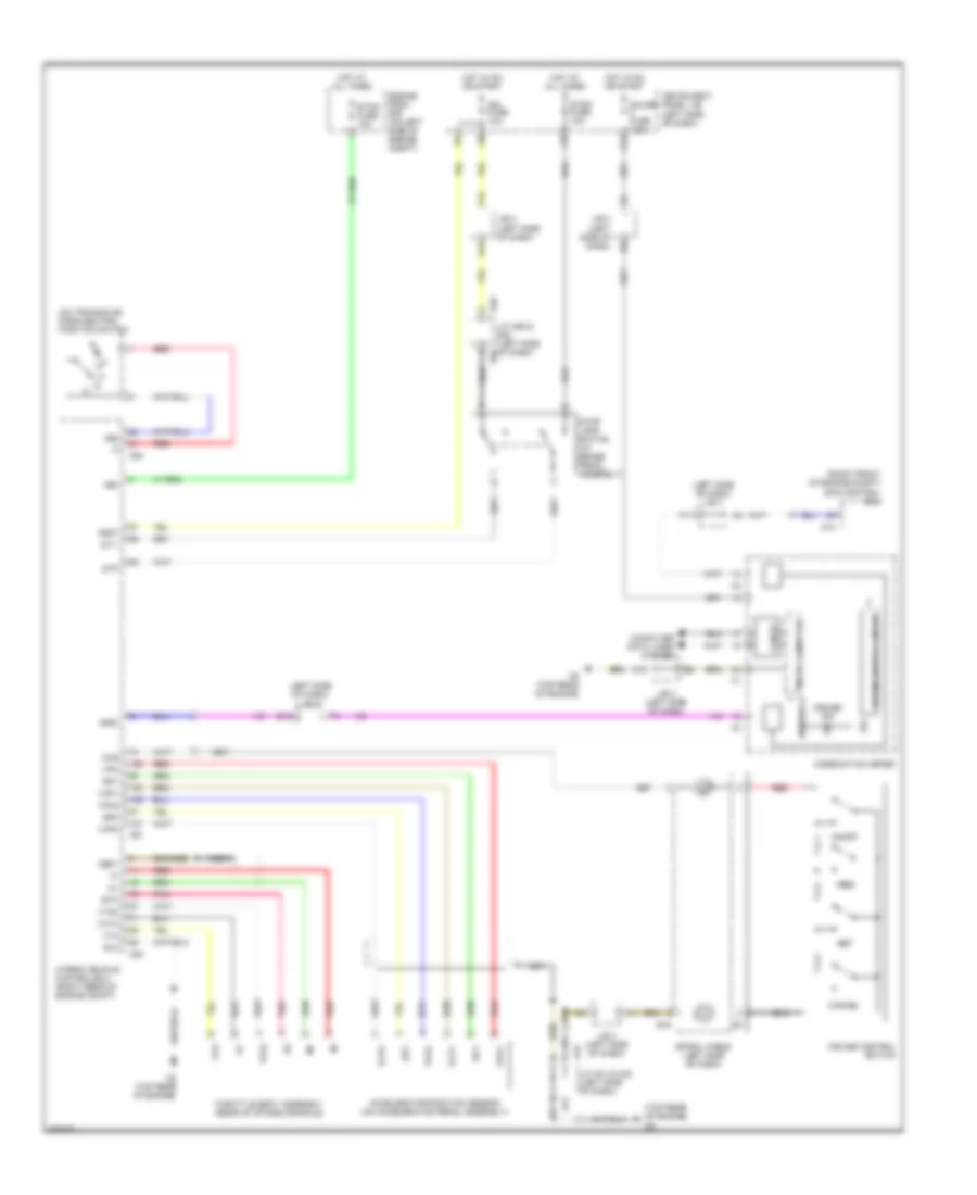
AIR CONDITIONING
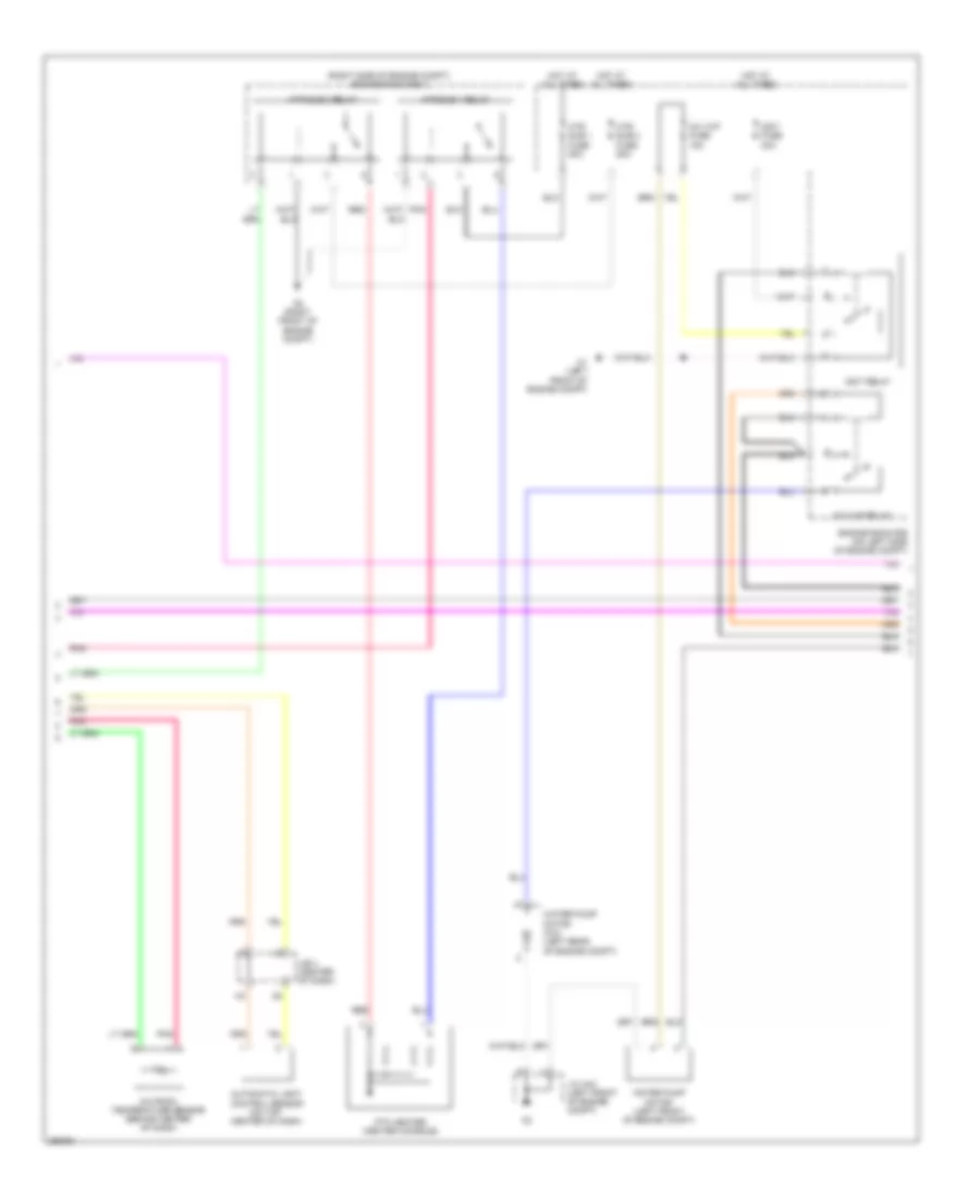
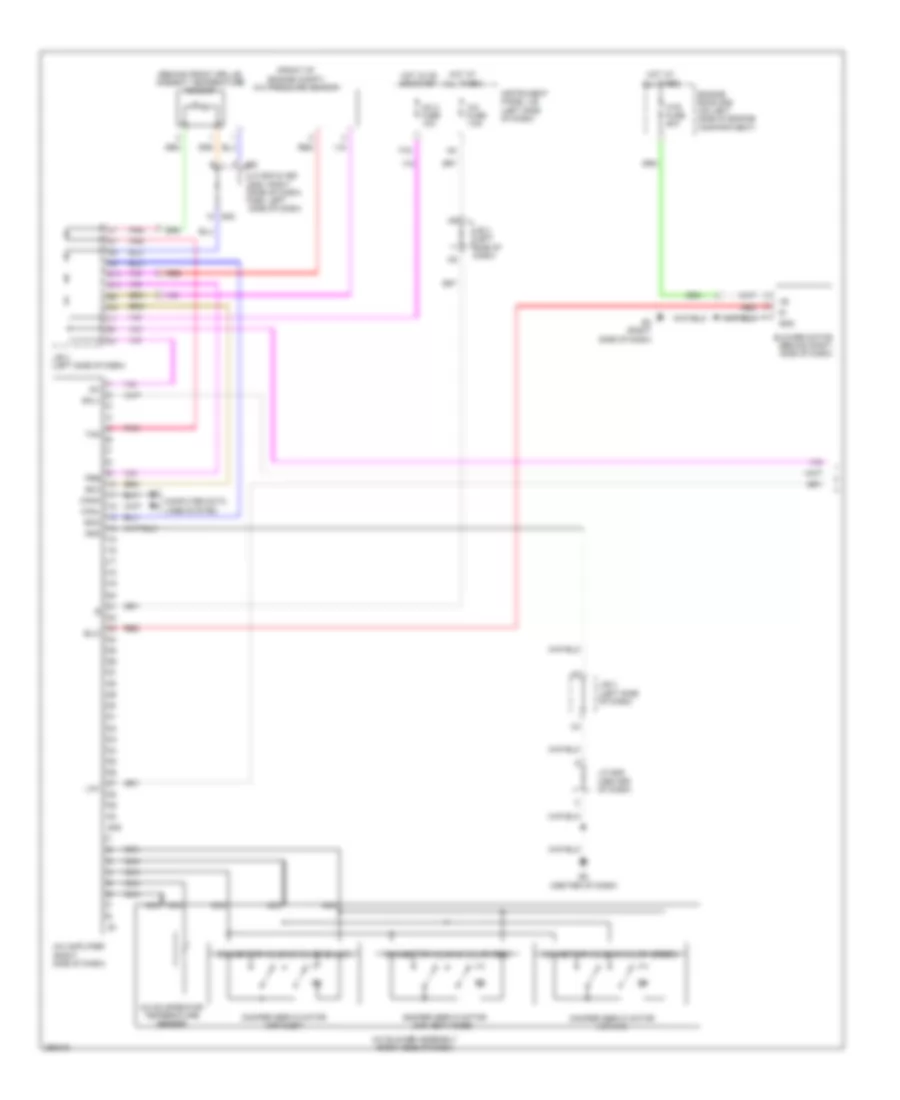
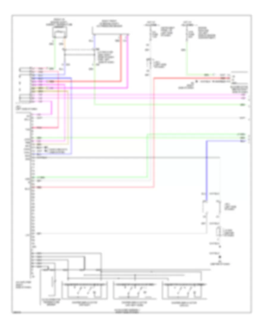
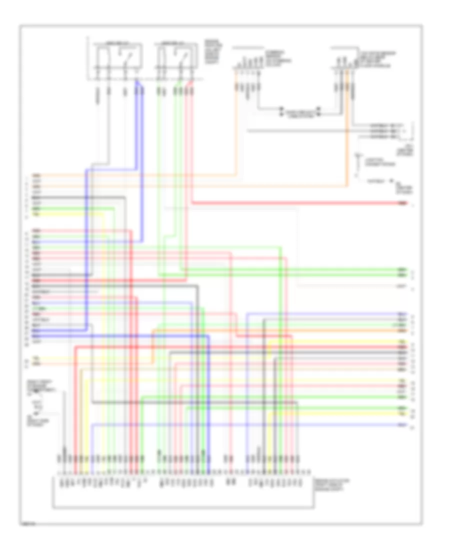
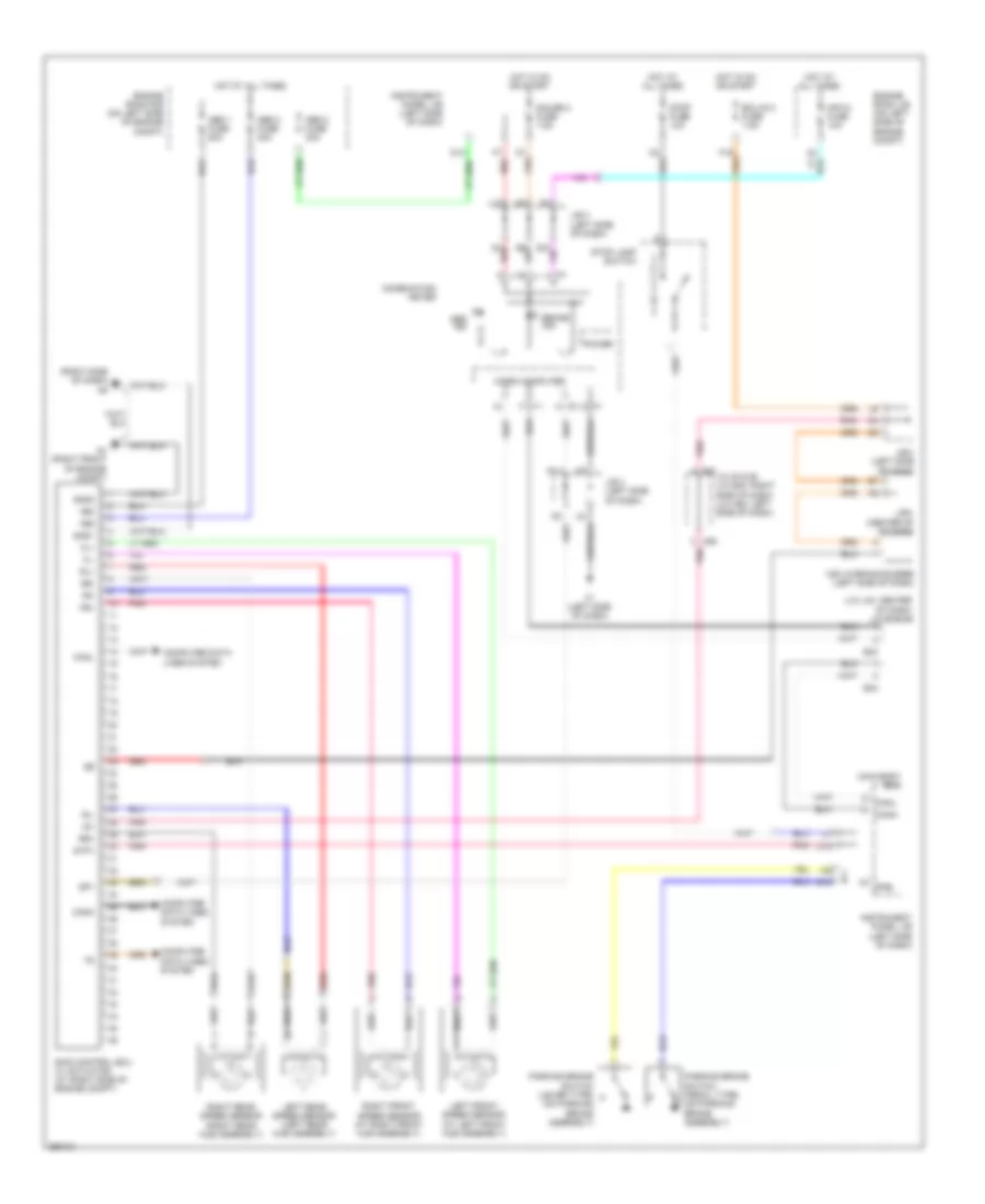
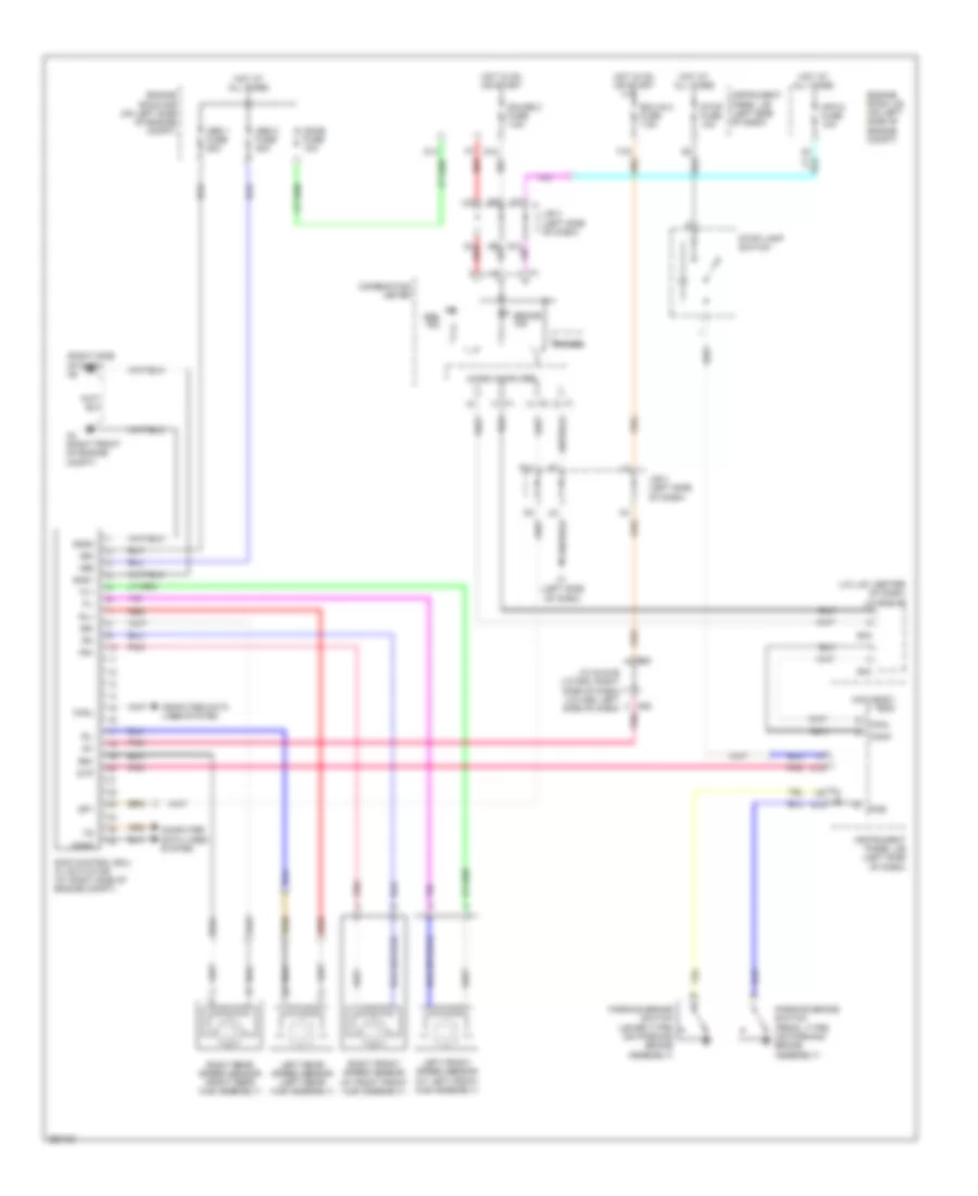
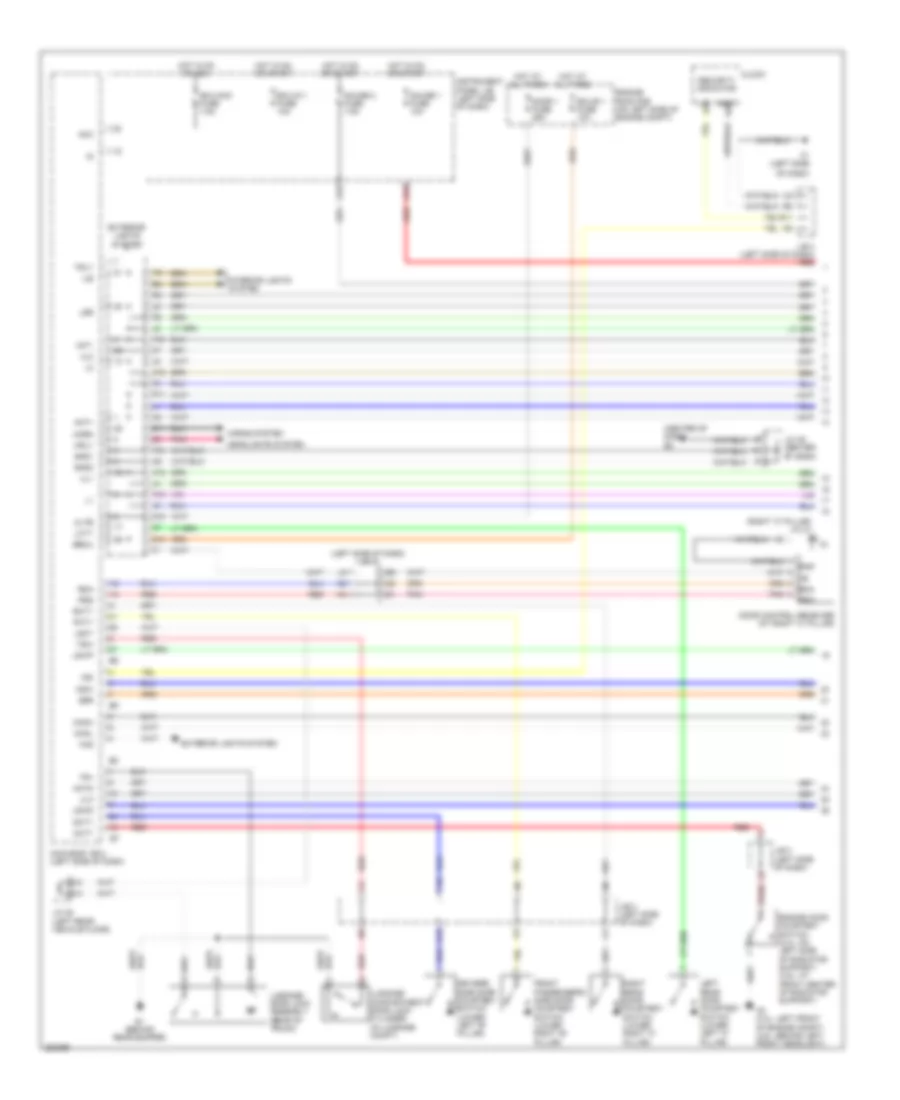
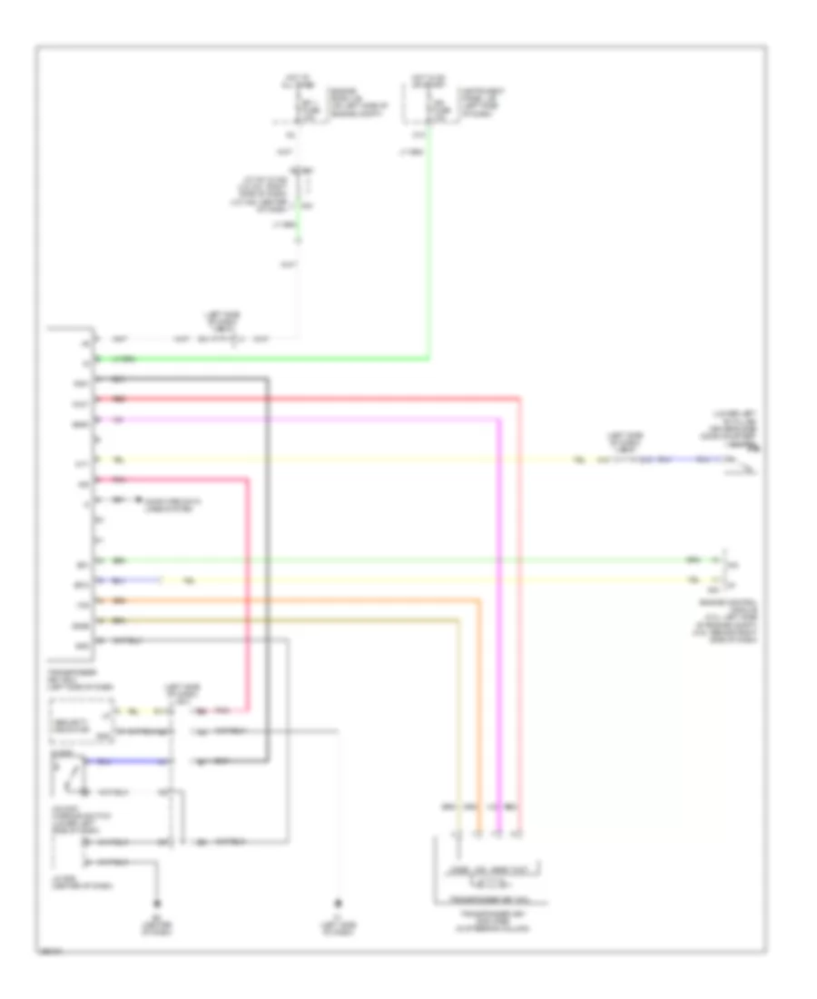
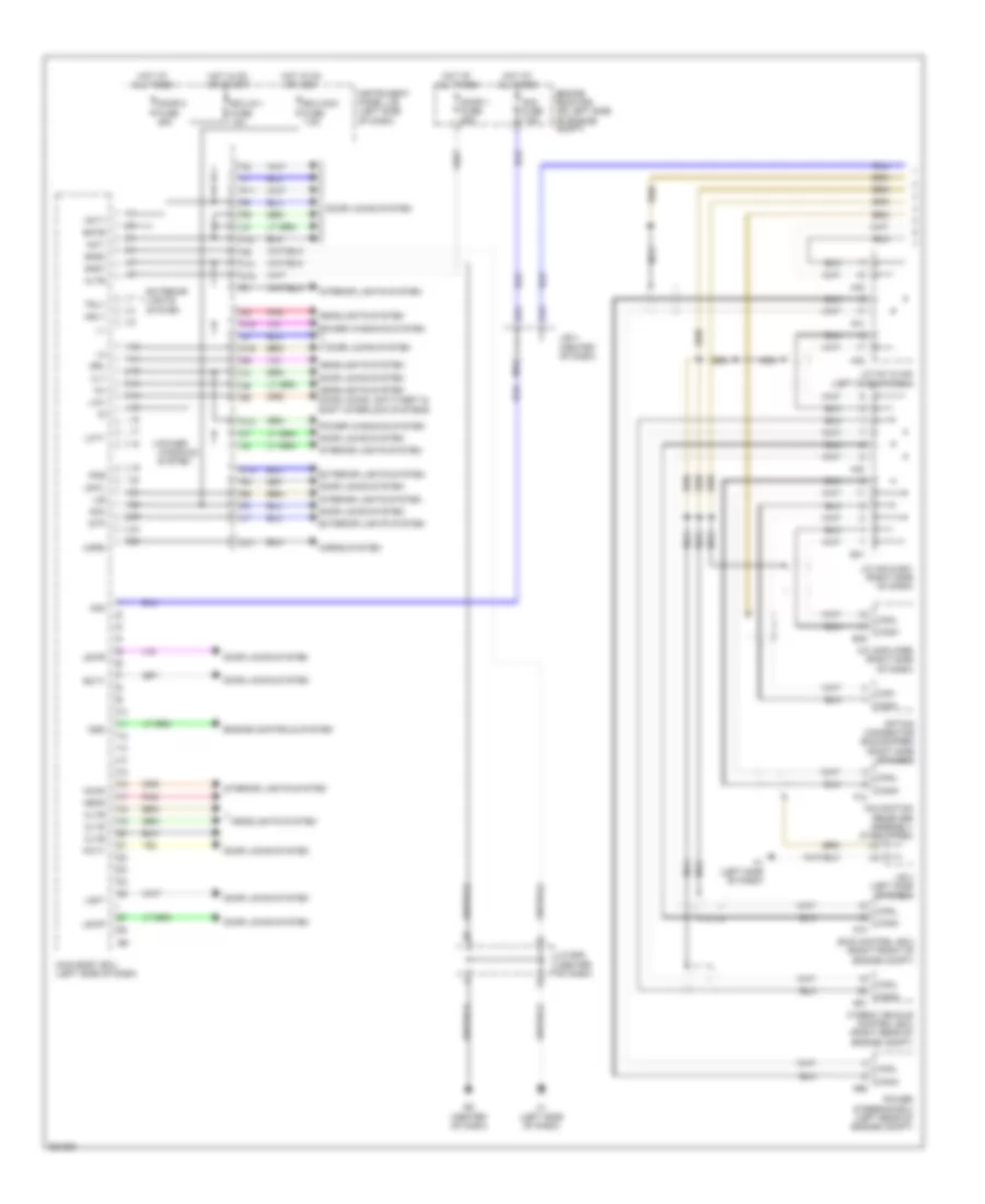
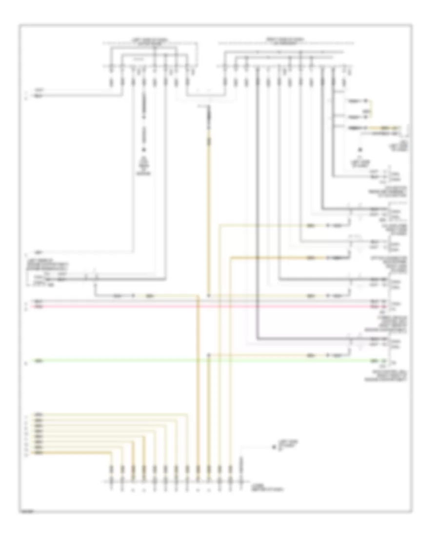
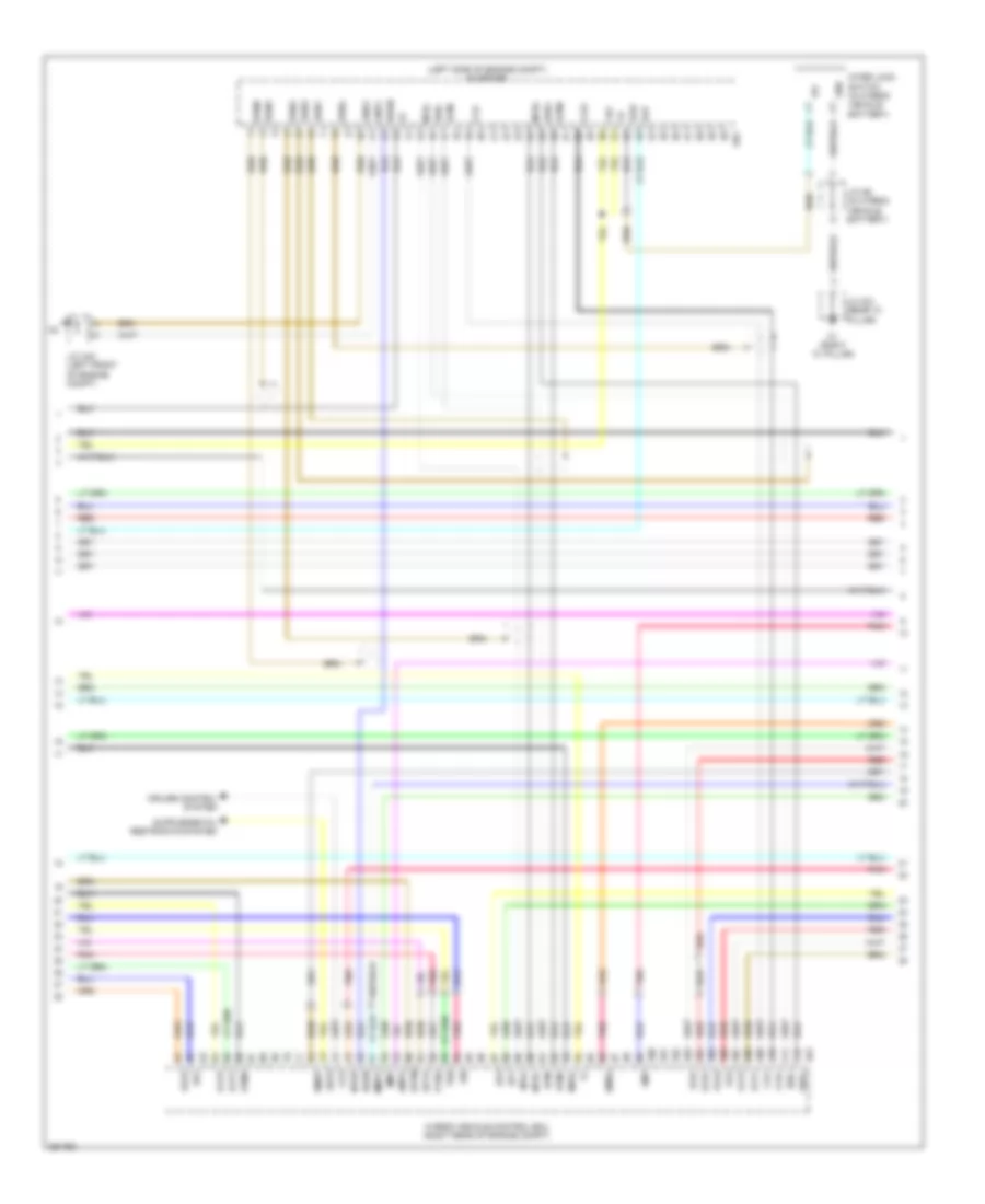
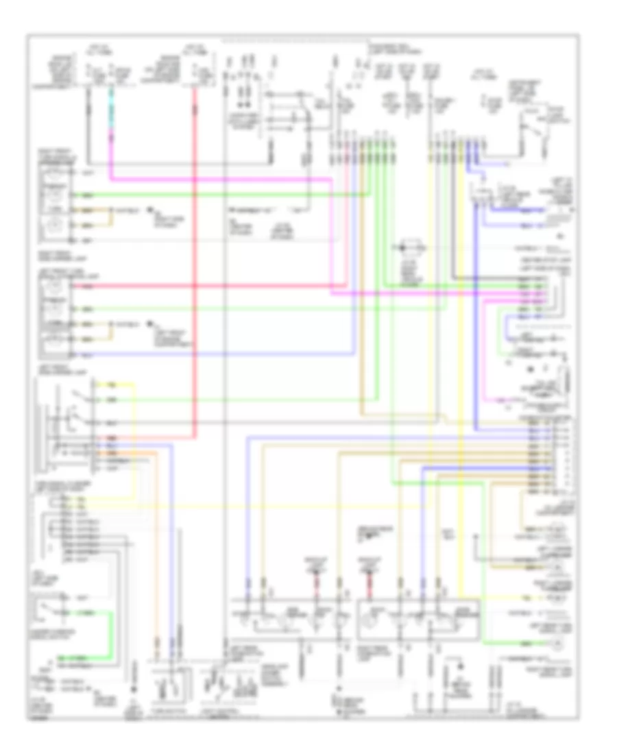
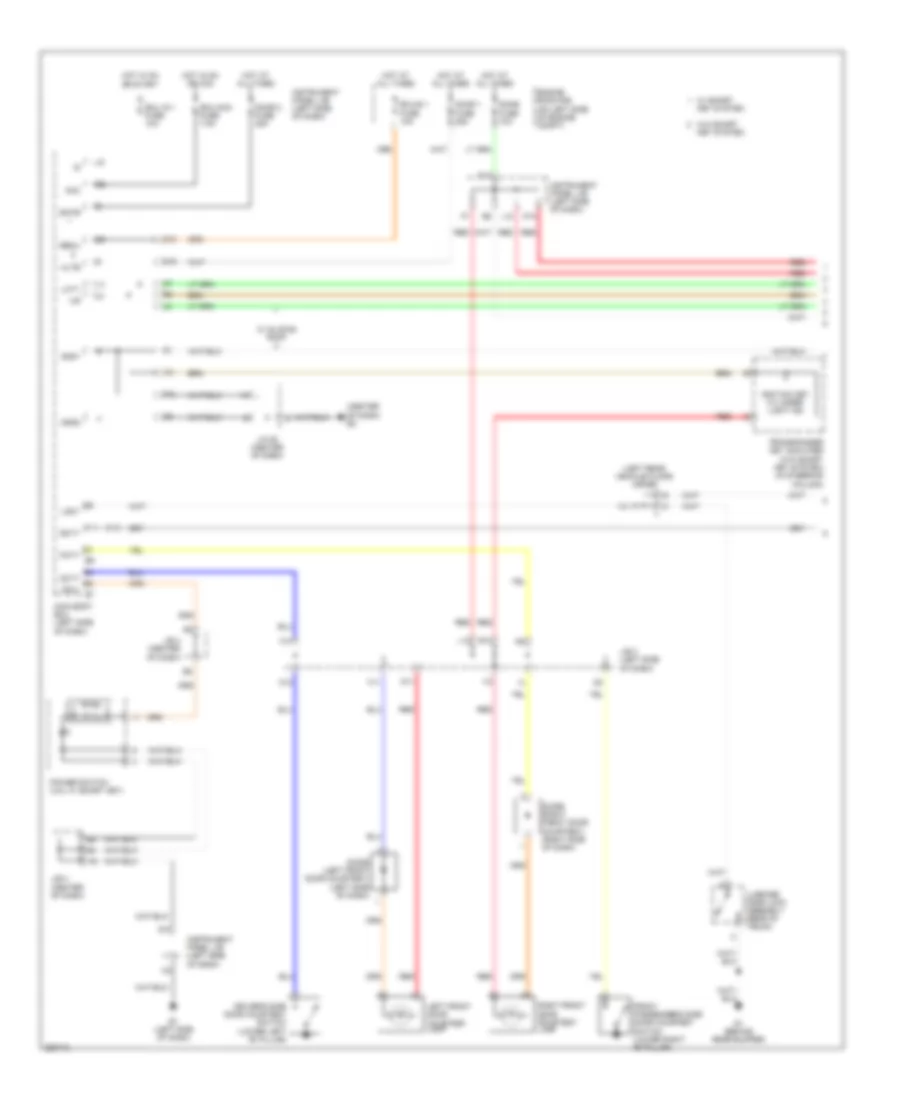
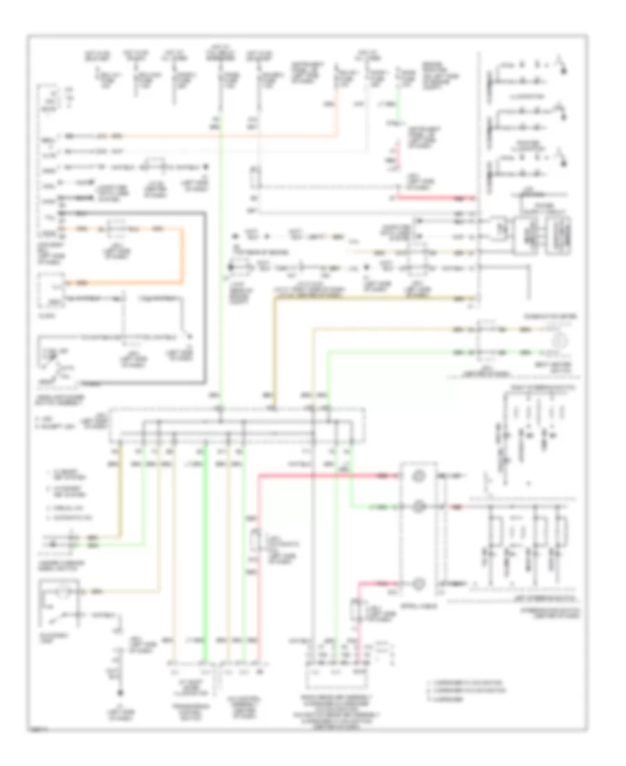
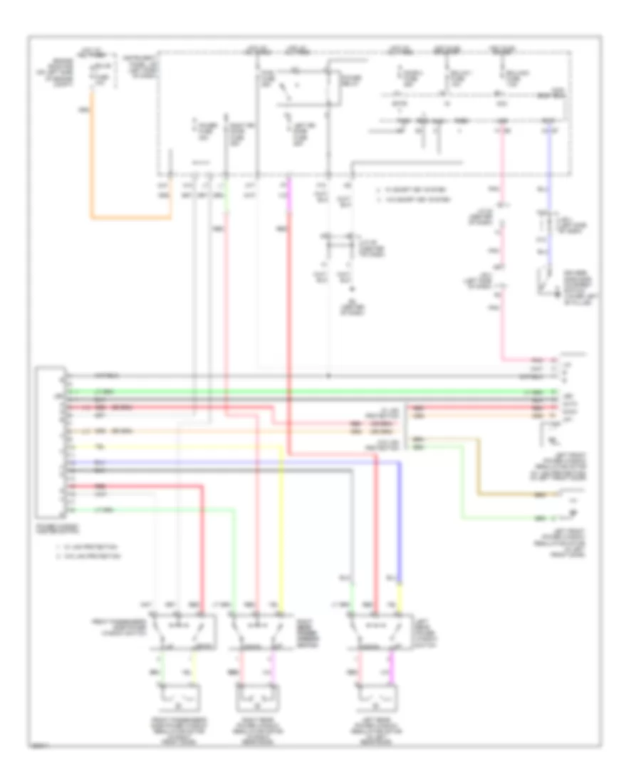
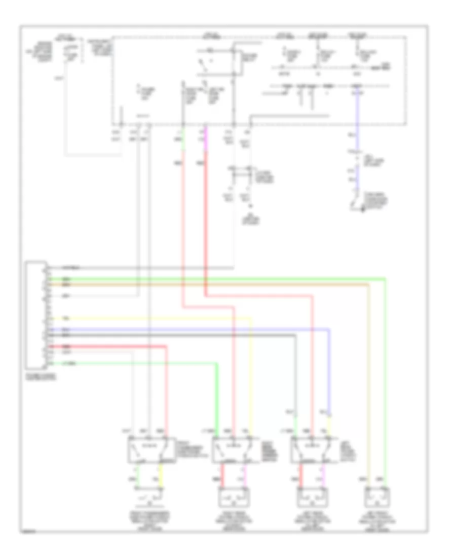
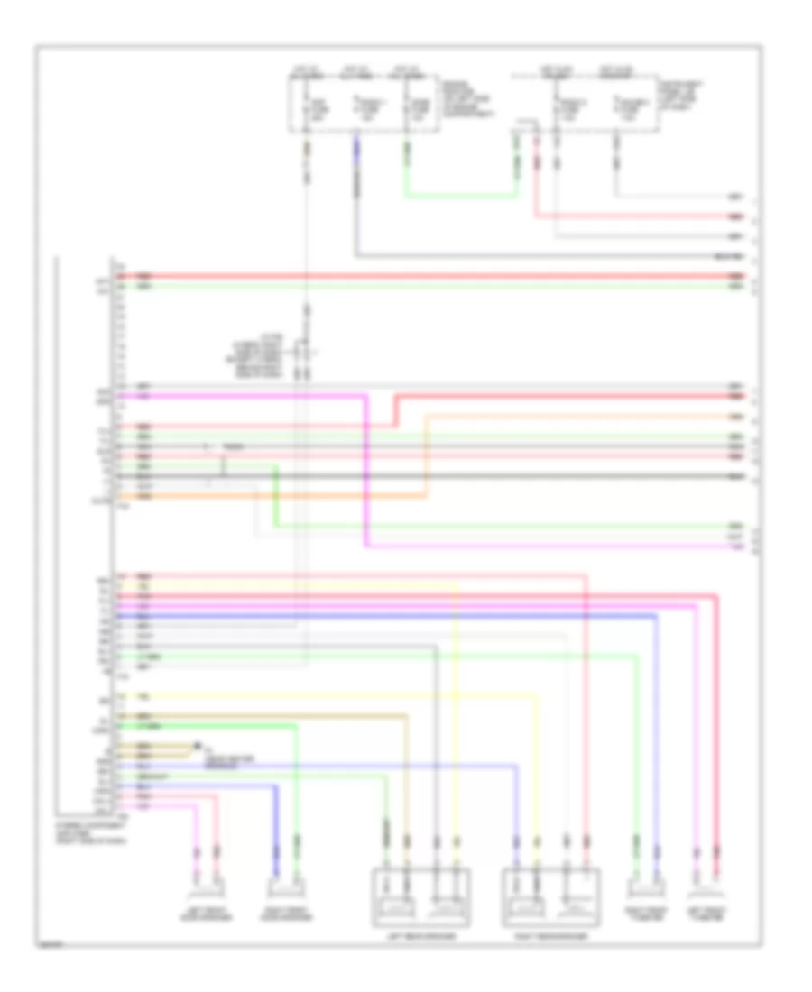
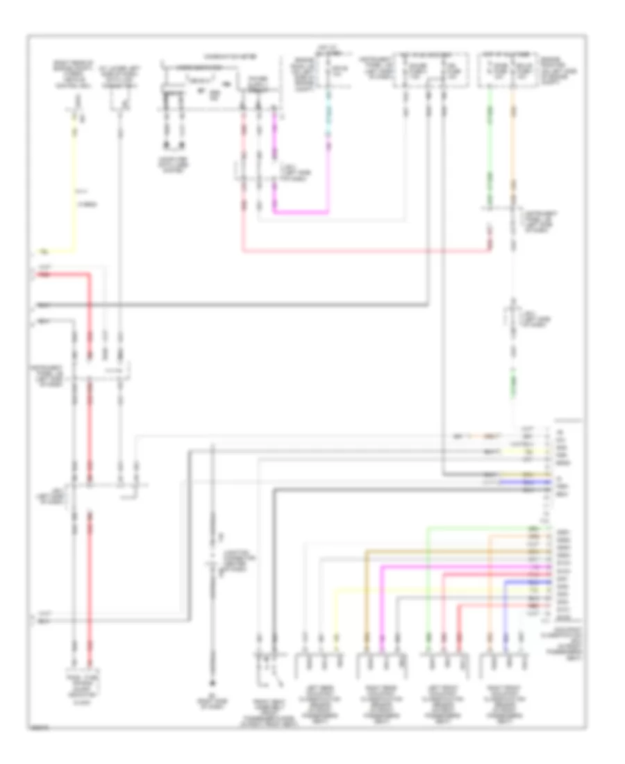
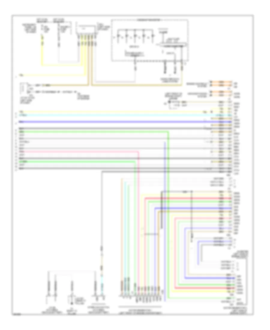
Automatic A/C Wiring Diagram, Hybrid (1 of 3) for Toyota Camry CE 2007
 https://portal-diagnostov.com/license.html
Automotive Electricians Portal FZCO
Automotive Electricians Portal FZCO
https://portal-diagnostov.com/license.html
https://portal-diagnostov.com/license.html
Automotive Electricians Portal FZCO
Automotive Electricians Portal FZCO
List of elements for Automatic A/C Wiring Diagram, Hybrid (1 of 3) for Toyota Camry CE 2007:
- (behind front grille) ambient temperature sensor
- (left side of dash) ion generator
- (right front of engine compt) a/c pressure sensor
- A/c amplifier (right side of dash)
- A/c blower assembly (right side of dash)
- A/c evaporator temperature sensor
- A/c fuse 7.5a
- A58
- Blower motor (behind right side of dash)
- Blw
- Canh
- Canl
- Computer data lines system
- Connector housing color (black)
- Connector housing color (green)
- Connector housing color (red)
- D11
- D12
- Damper servo motor (air inlet)
- Damper servo motor (air mix driver side)
- Damper servo motor (air mix front passenger side)
- Damper servo motor (air vent mode)
- E2 (center of dash)
- E3 (right side of dash)
- E38
- E40
- Ecid
- Eco heat/cool
- Eco switch
- Ecos
- Engine room r/b (on left side of engine compartment)
- Gnd
- H11
- H12
- Hot at all times
- Htr fuse 50a
- Ig+
- Instrument panel j/b (left side of dash)
- J/b 3 (left side of dash)
- J/b 4 (center of dash)
- J/c a58 & e40 (left side of dash)
- J/c e49 (center of dash)
- L10
- L11
- L12
- Lin1
- M11
- Nca
- Pcd1
- Pnk
- Pre
- Ptc1
- Ptc2
- Red
- S5-3
- Sg-1
- Sg-2
- Tam
- Tsd
- Tsp
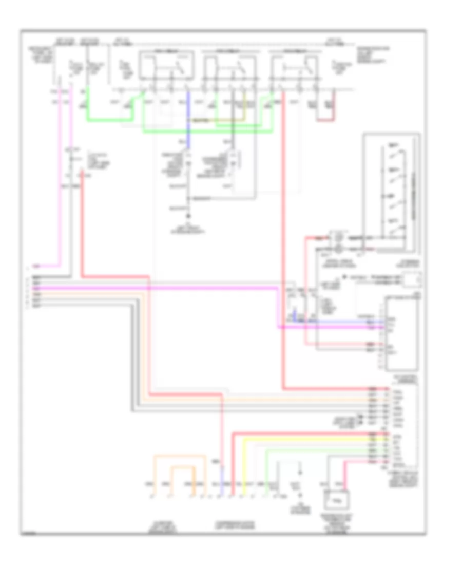
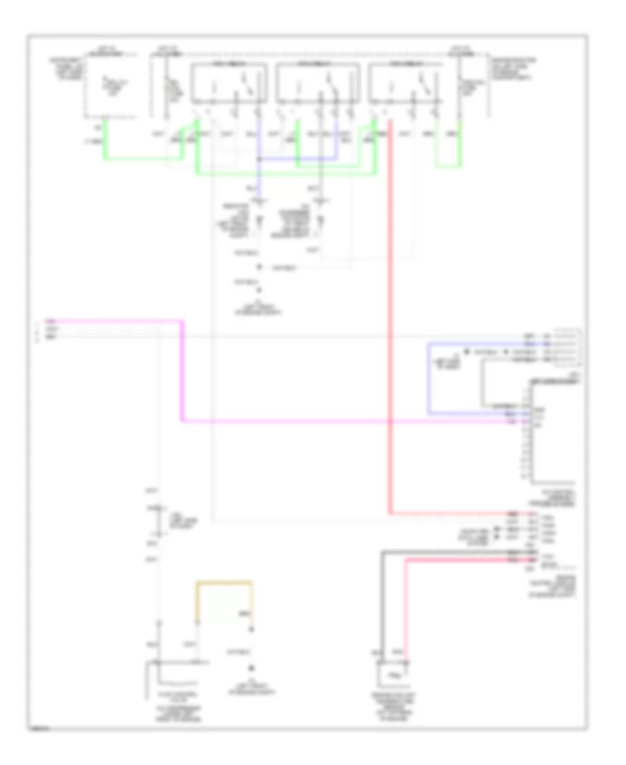
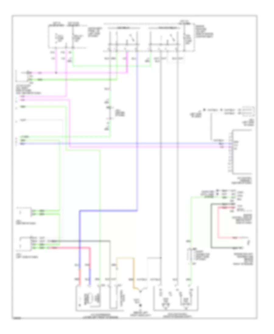
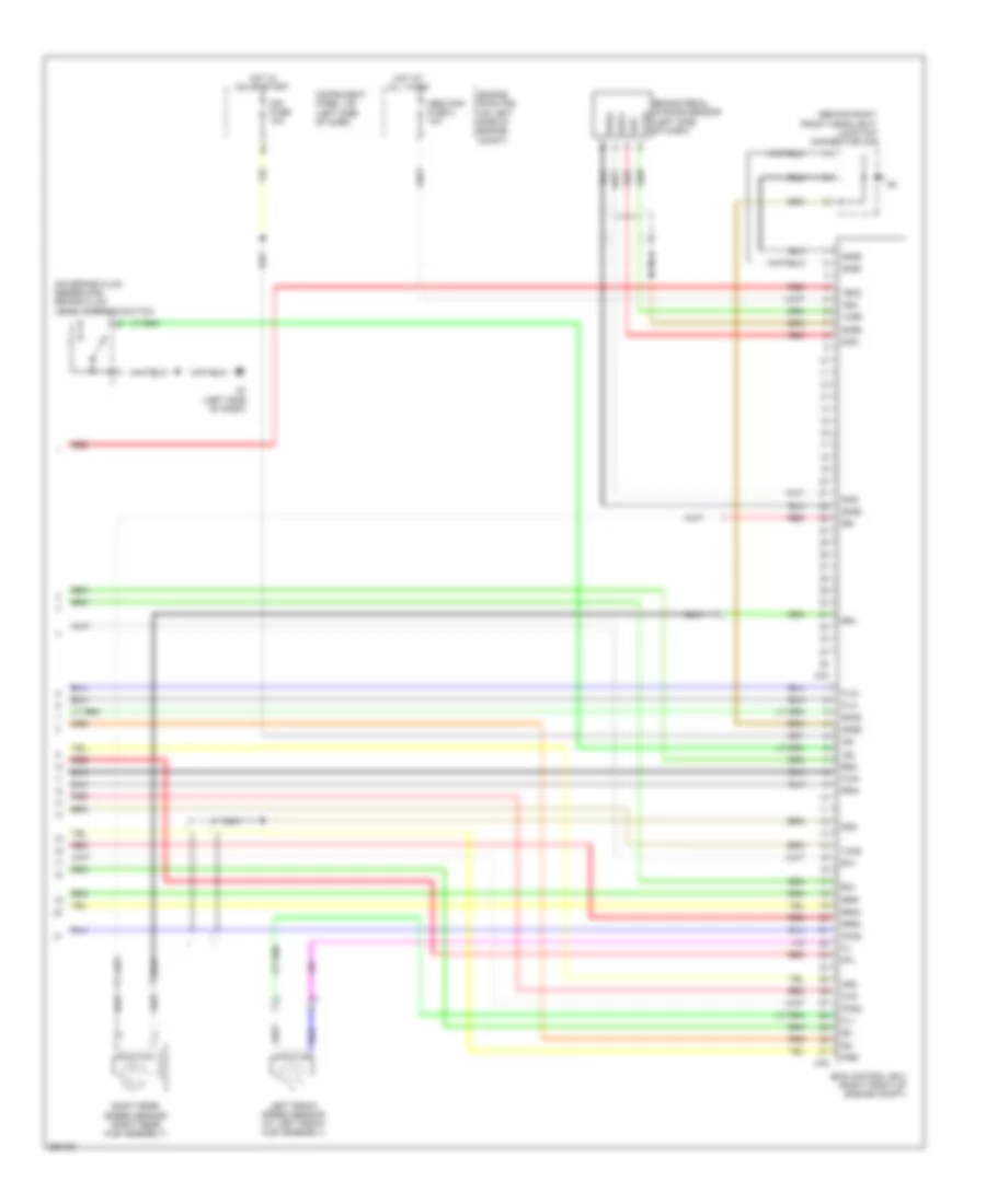
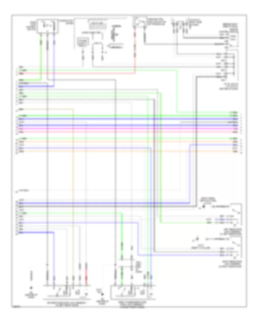
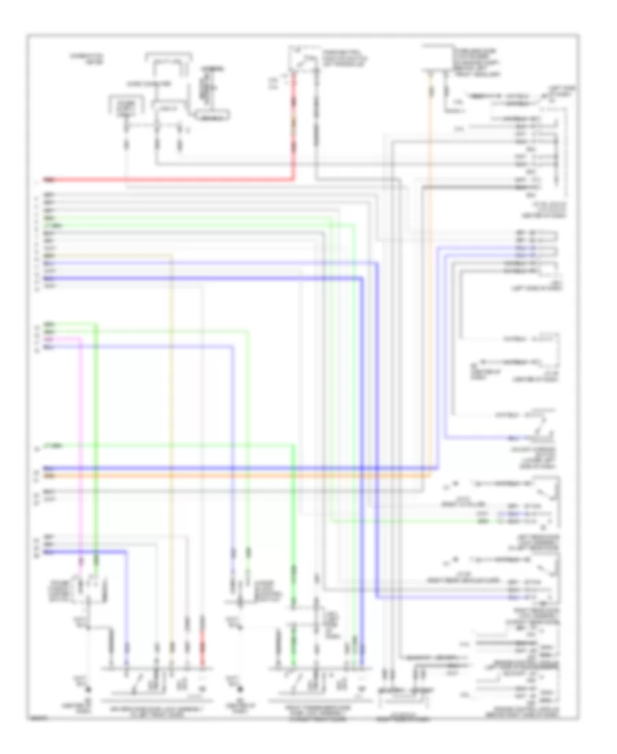
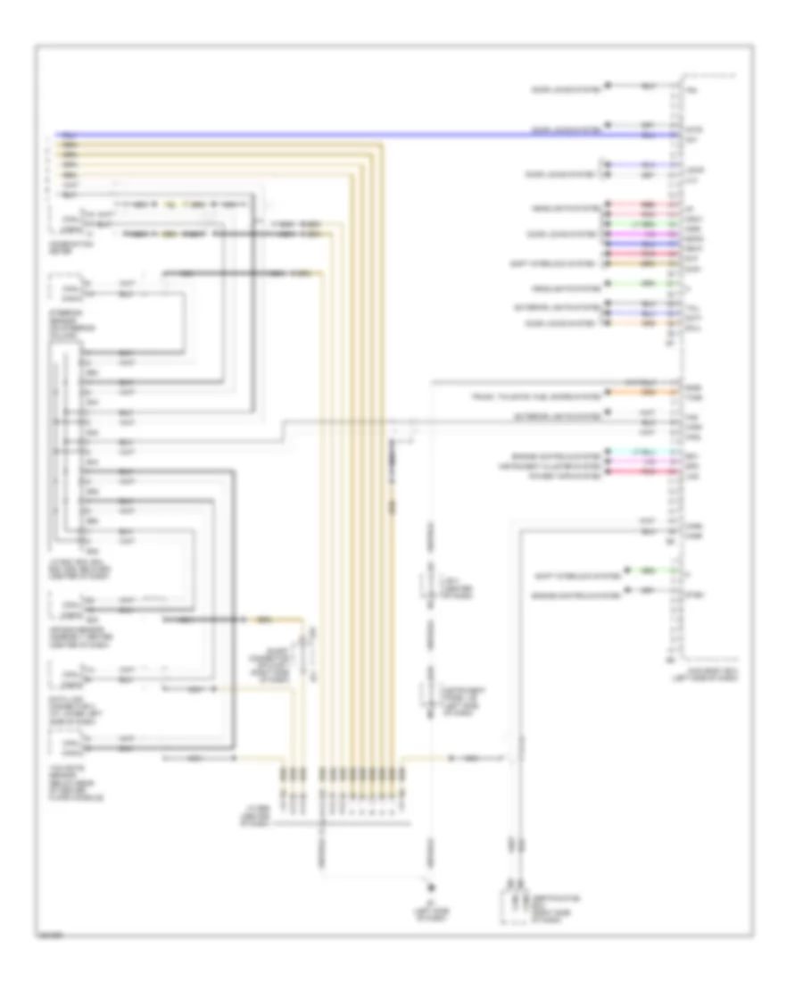
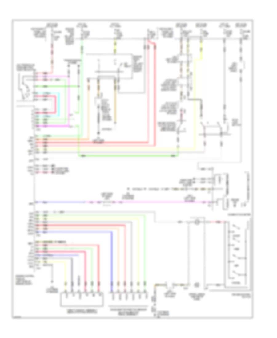
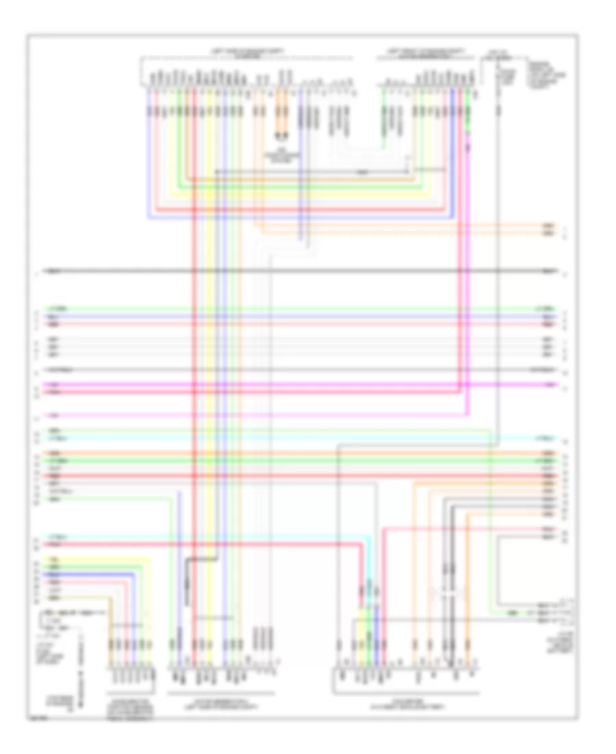
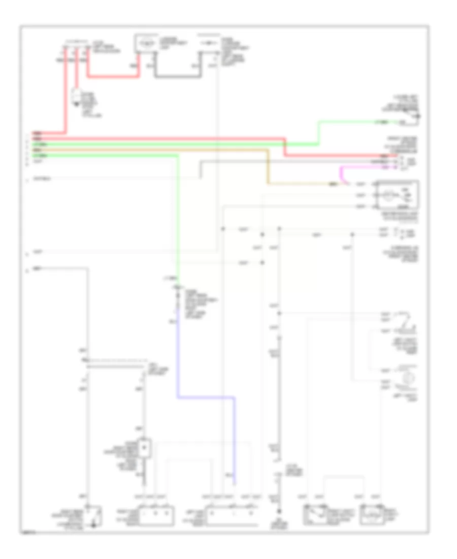
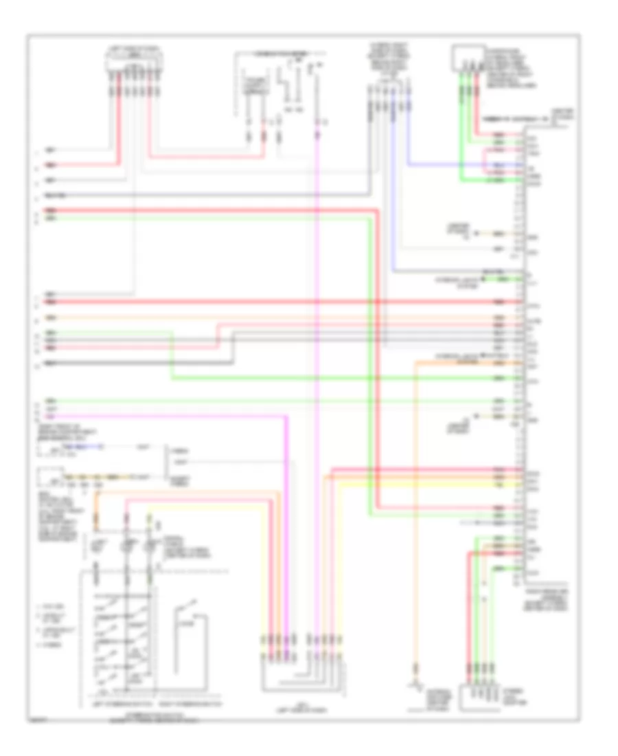
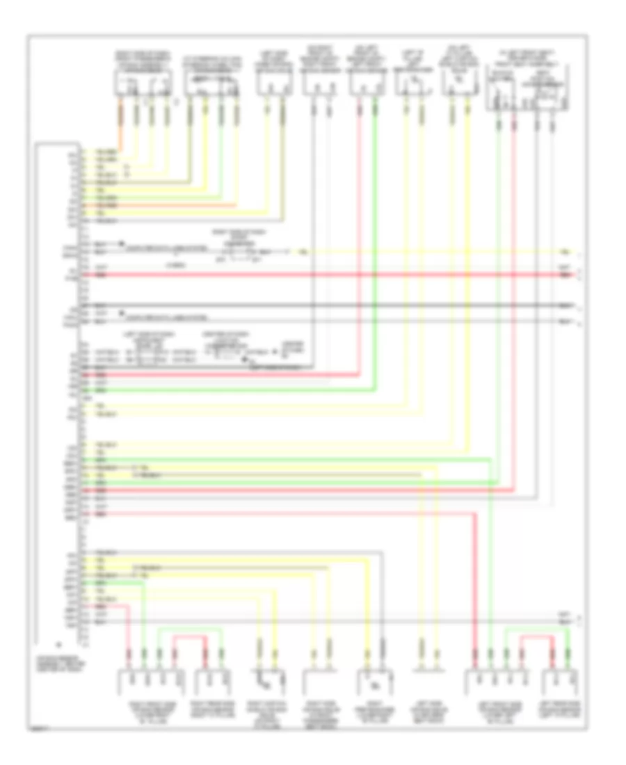
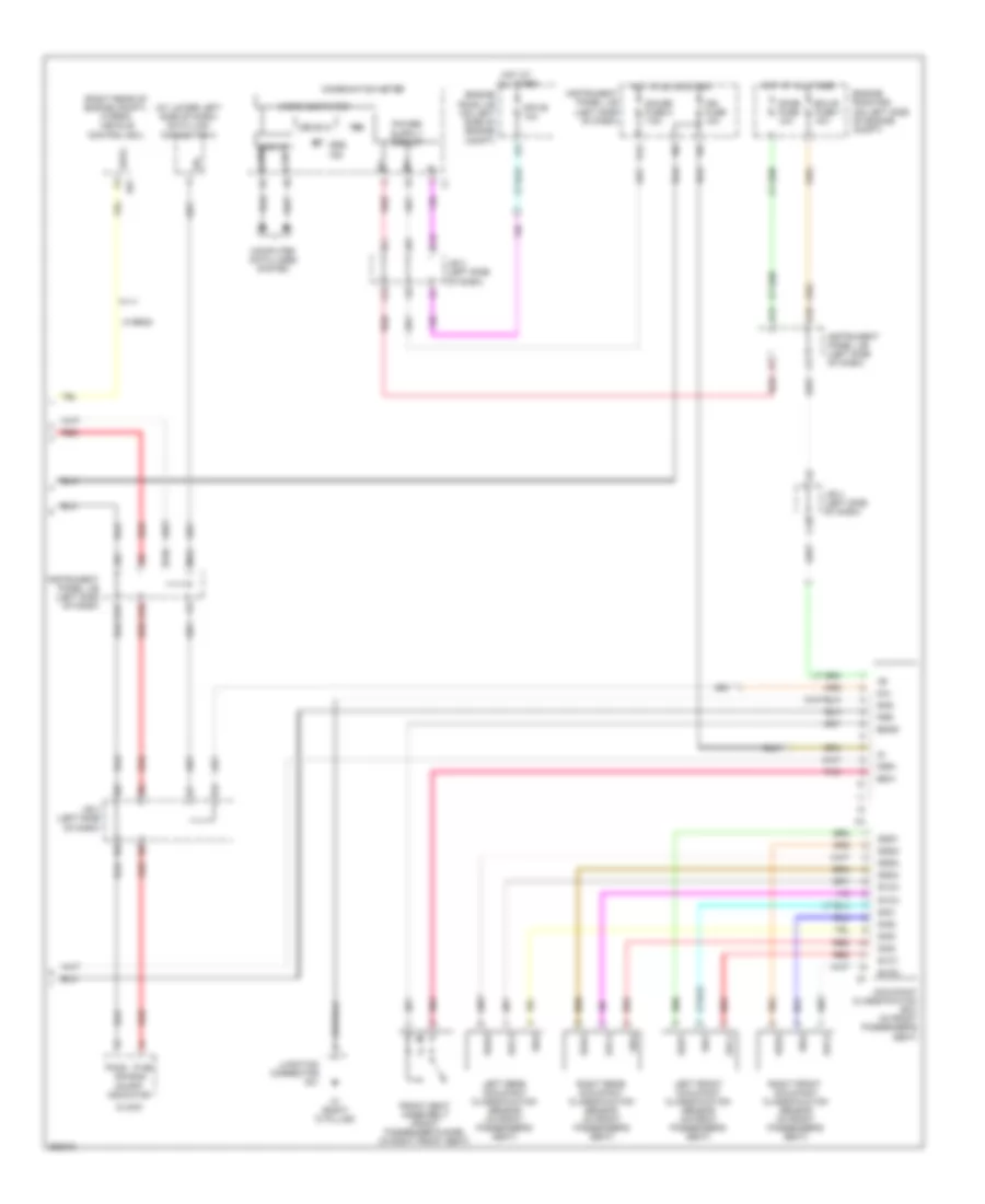
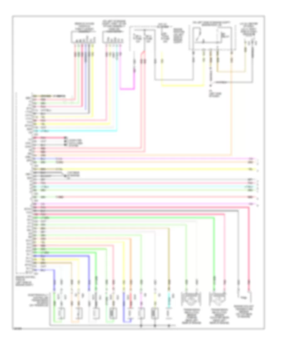
Automatic A/C Wiring Diagram, Hybrid (2 of 3) for Toyota Camry CE 2007
List of elements for Automatic A/C Wiring Diagram, Hybrid (2 of 3) for Toyota Camry CE 2007:
- (right side of engine compt) engine room r/b 3
- A/c room temperature sensor (behind center of dash)
- A/c w/p relay
- A1 (left front of engine compt)
- A8 (right front of engine compt)
- Automatic light control sensor (on top center of dash)
- Engine room r/b (on left side of engine compt)
- Hot at all times
- Htr sub 1 fuse 50a
- Htr sub 1 relay
- Htr sub 2 fuse 50a
- Htr sub 2 relay
- Igct fuse 30a
- Igct relay
- Inv w/p fuse 15a
- J/b 4 (center of dash)
- J/c a43 (left front of engine compt)
- Pnk
- Ptc heater (center console)
- Red
- Water pump motor (a/c) (left rear of engine compt)
- Water pump motor (left front of engine compt)
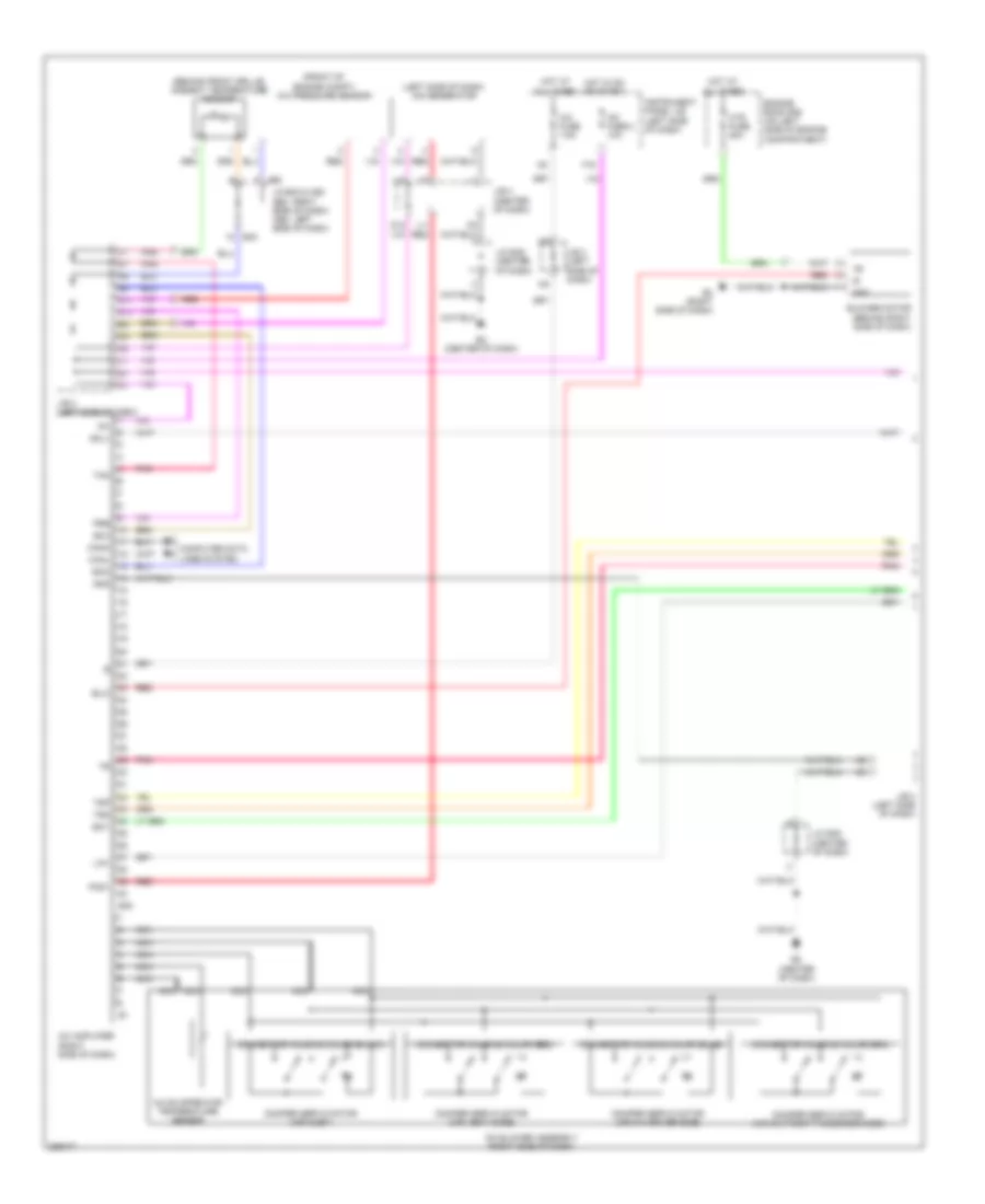
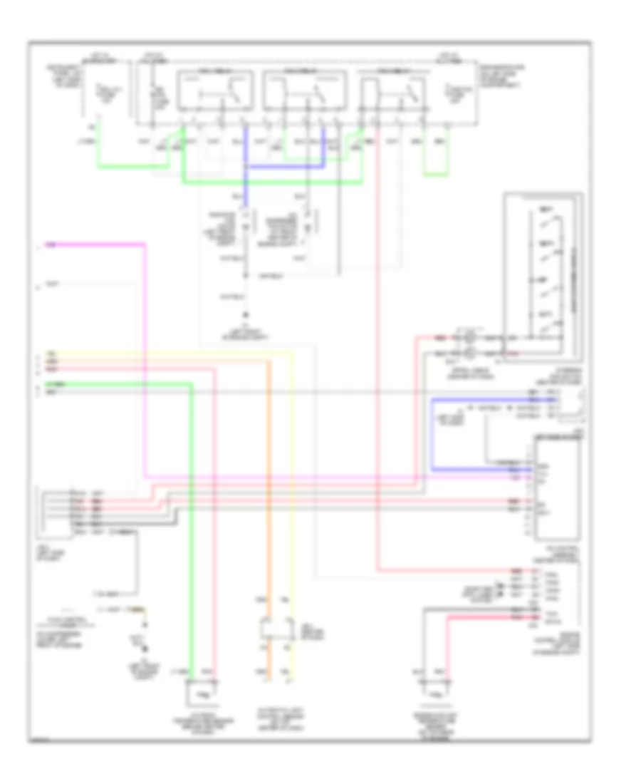
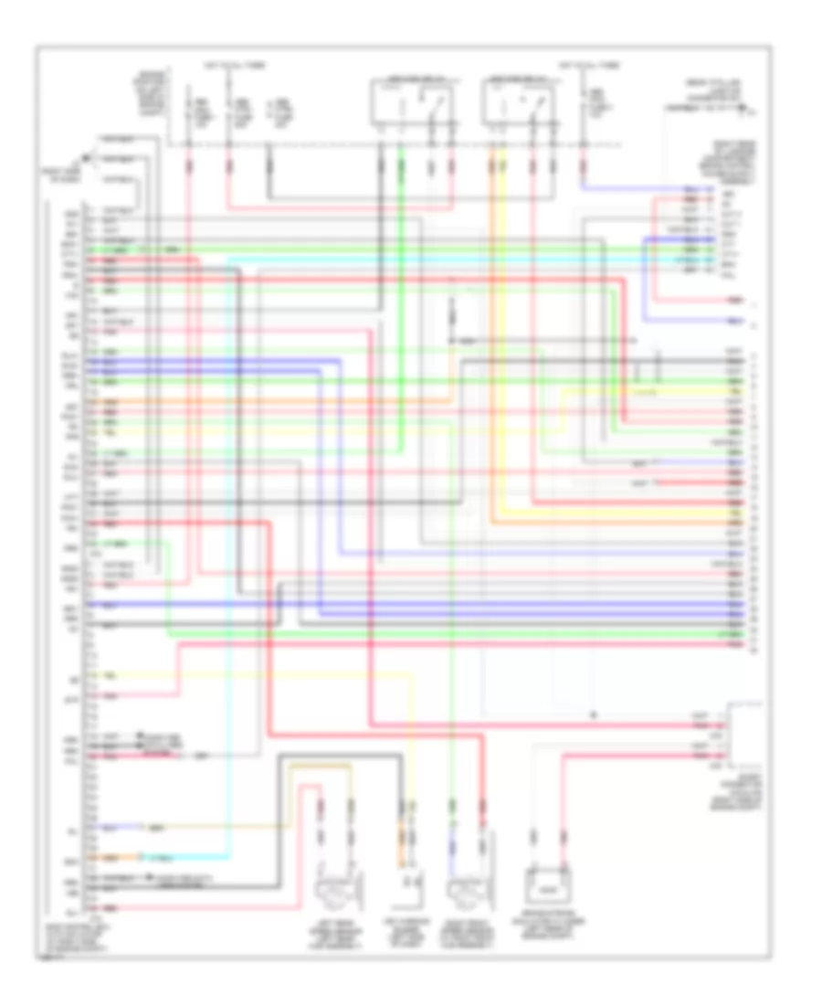
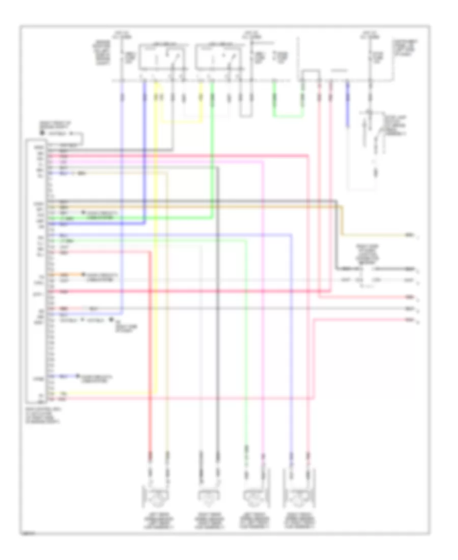
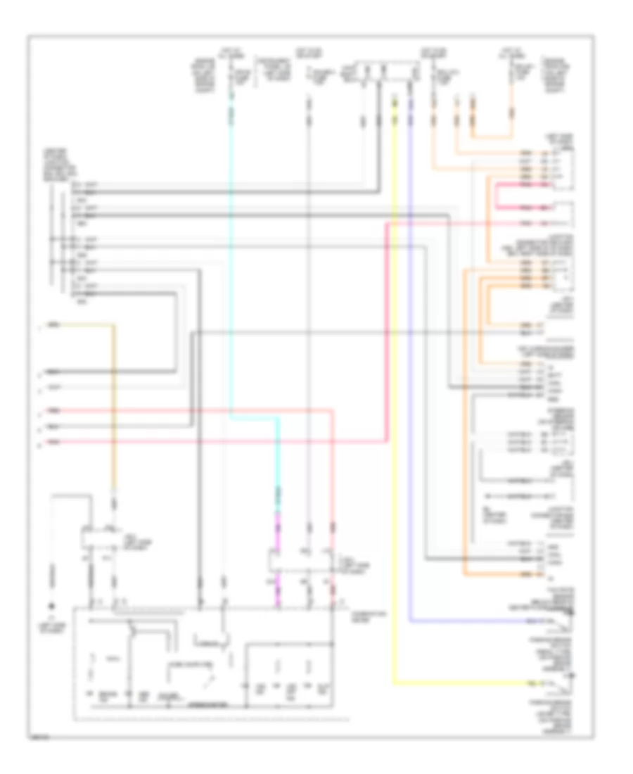
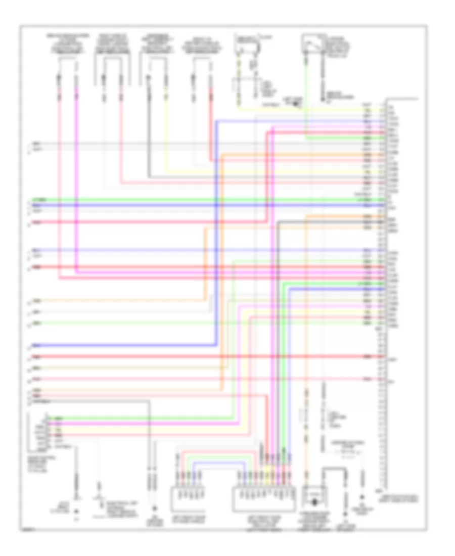
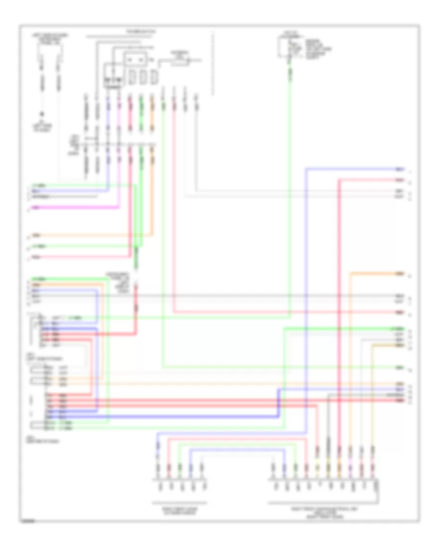
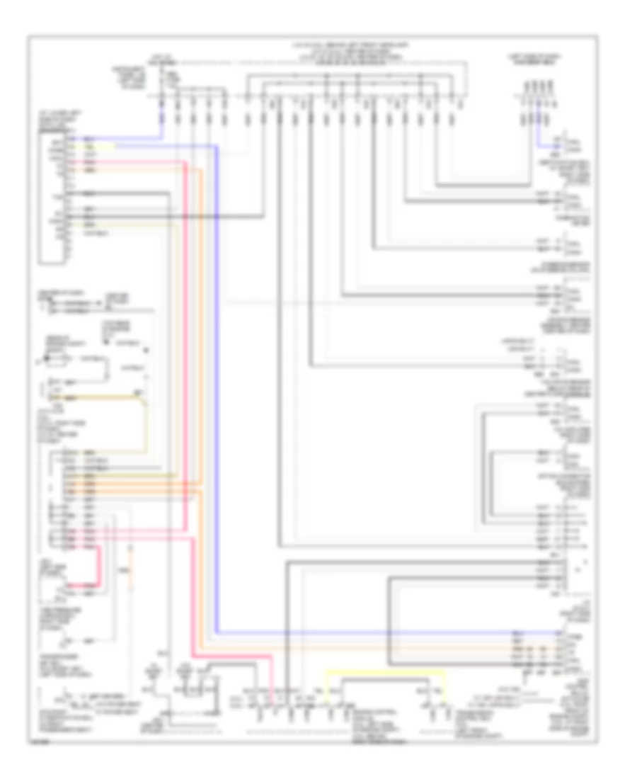
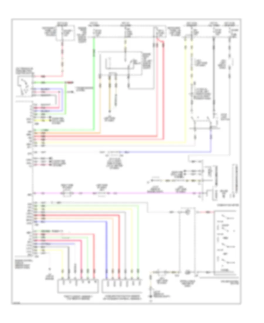
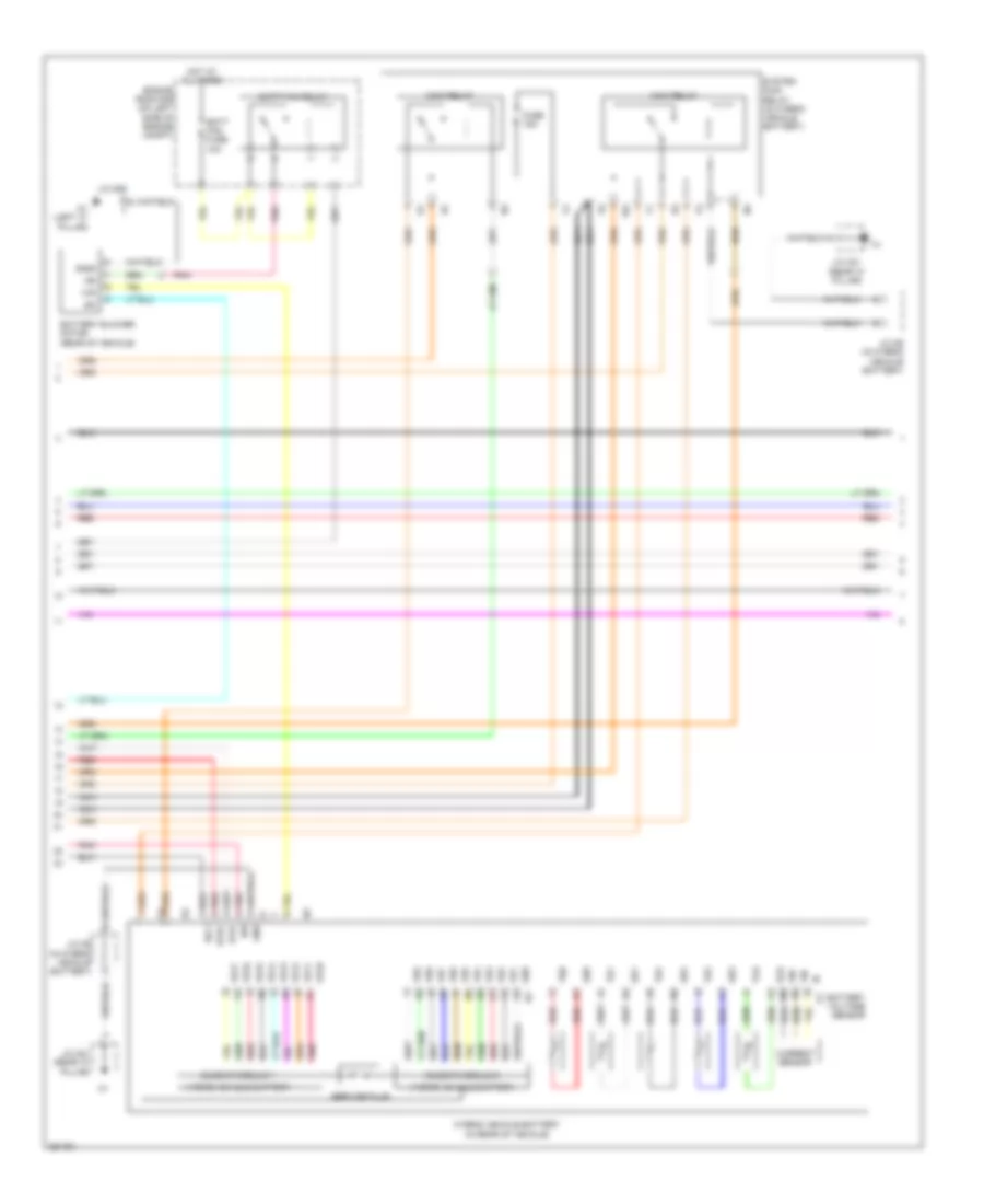
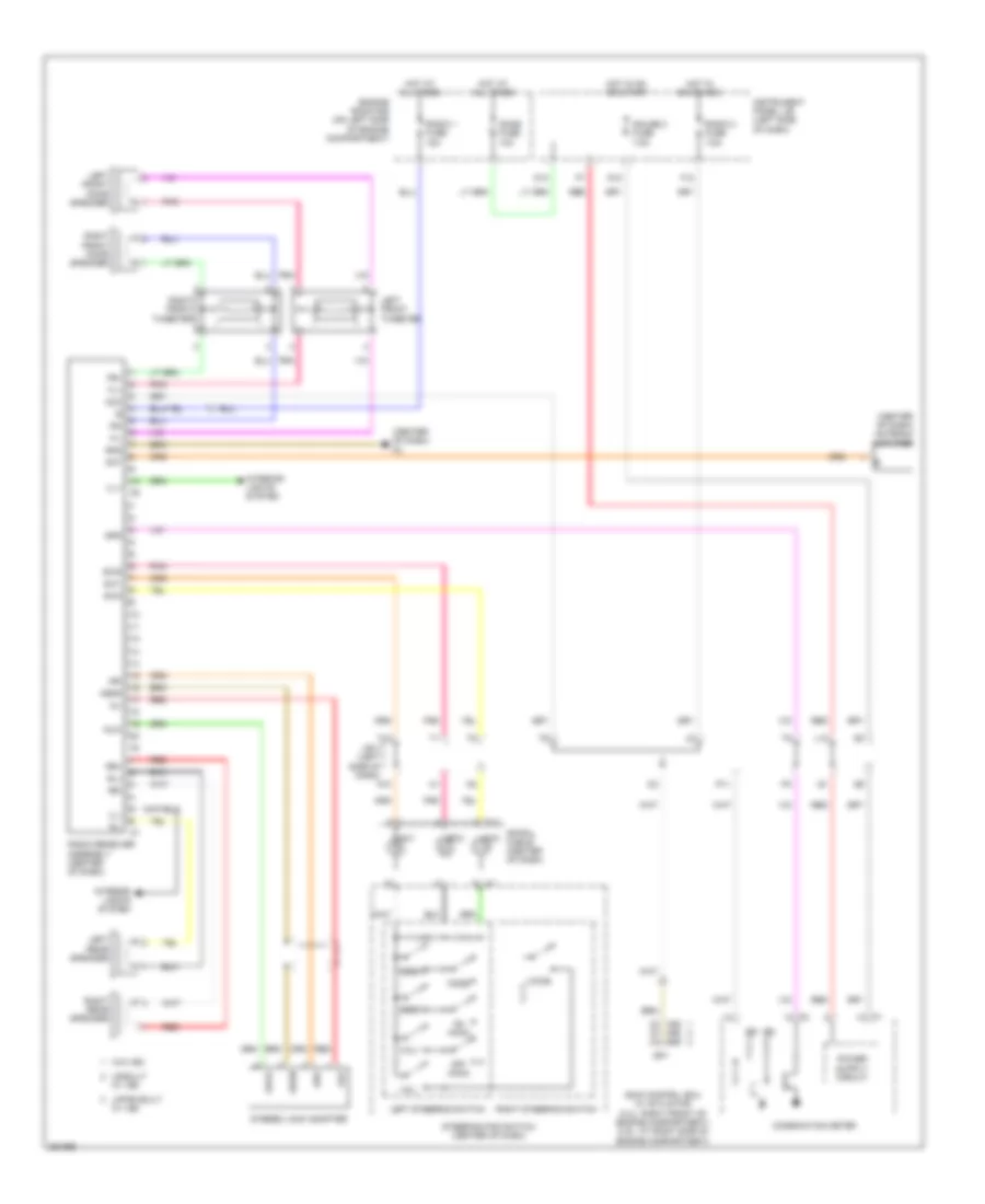
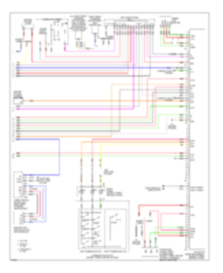
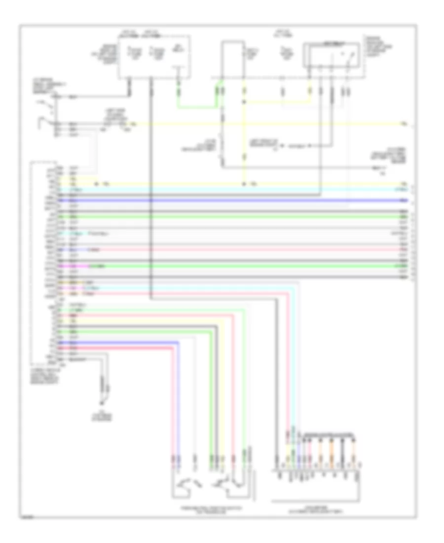
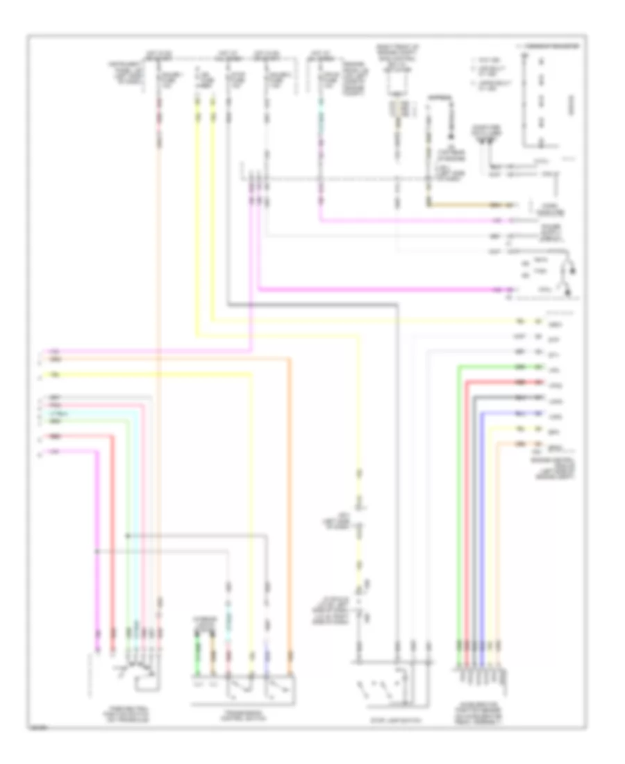
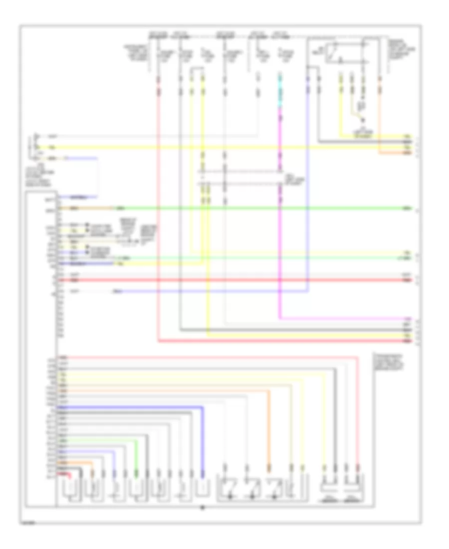
Automatic A/C Wiring Diagram, Hybrid (3 of 3) for Toyota Camry CE 2007
List of elements for Automatic A/C Wiring Diagram, Hybrid (3 of 3) for Toyota Camry CE 2007:
- A/c 2 fuse 10a
- A/c condenser fan motor (front center of engine compt)
- A/c control assembly
- A1 (left front of engine compt)
- A41
- A42
- A61
- Ad11
- Auto
- C6 (top rear of engine)
- C63
- C64
- Canh
- Canl
- Cds fan fuse 40a
- Clk
- Compressor motor (left side of engine)
- Computer data lines system
- D12
- E18
- Ecu ig 1 fuse 10a
- Engine coolant temperature sensor (on top rear of engine)
- Engine room r/b (on left side of engine compt)
- Ethw
- Eti
- F1 (left side of dash)
- F16
- Fan 1 relay
- Fan 2 relay
- Fan 3 relay
- Fanh
- Fanl
- Gnd
- Hot at all times
- Hot in on or start
- Hybrid vehicle control ecu (right rear of engine compt)
- Ig+
- Instrument panel j/b (left side of dash)
- Inverter (left side of engine compt)
- Ite
- J/b 3 (left side of dash)
- J/c a41 & a42 (left side of dash)
- Mrel
- Nca
- Off
- Pnk
- Radiator fan motor (front of engine compt)
- Rdi fan fuse 40a
- Red
- Right steering switch
- S12
- Spiral cable (center of dash)
- Stb
- Steering pad switch
- Swp
- Temp+
- Temp-
- Thw
- Tx+
2.4L
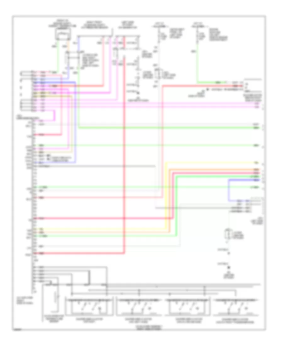
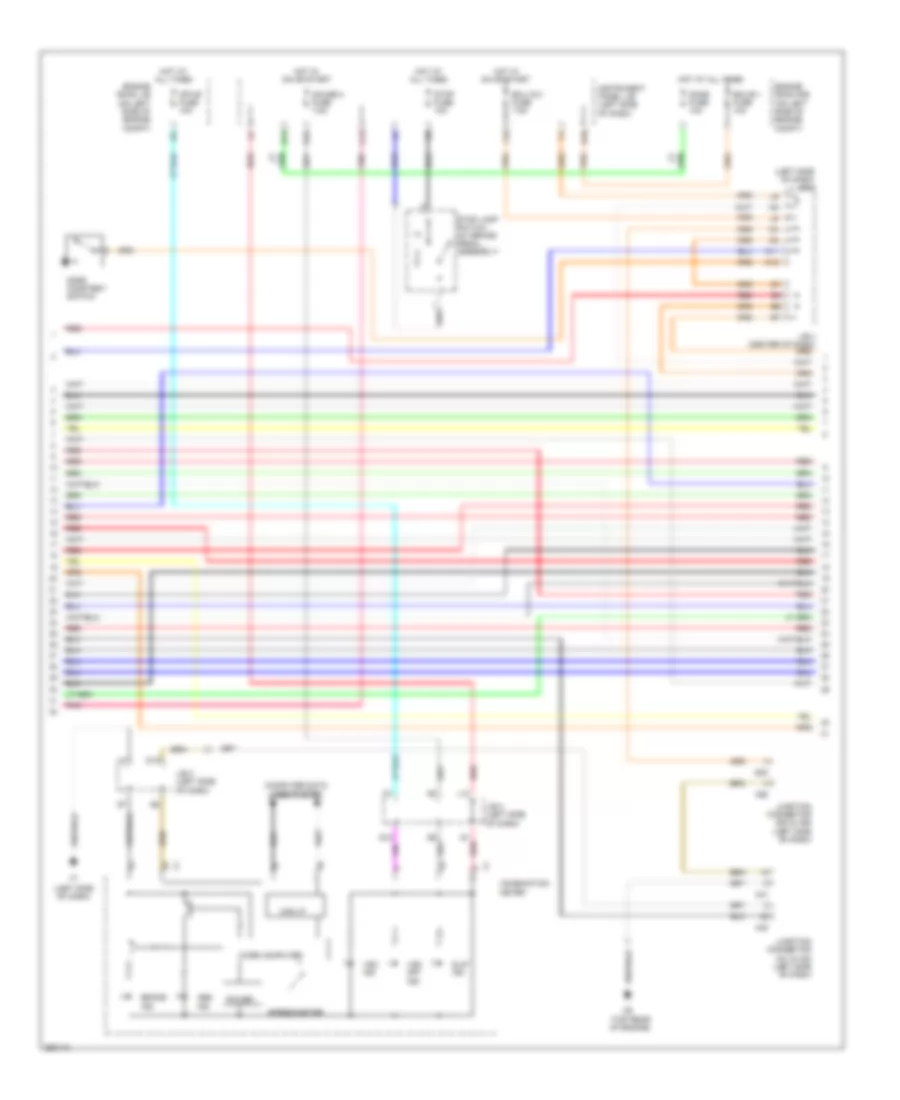
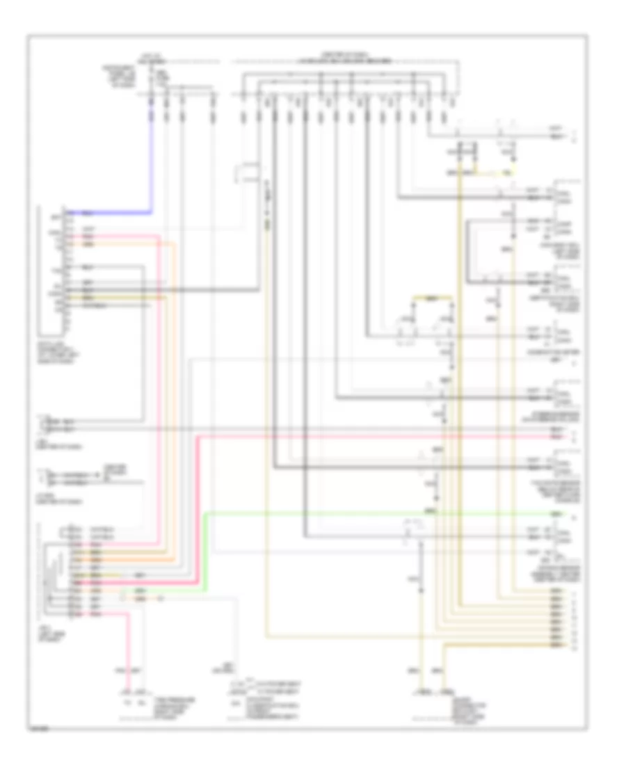
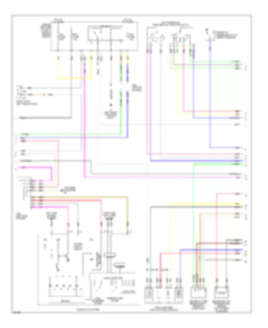
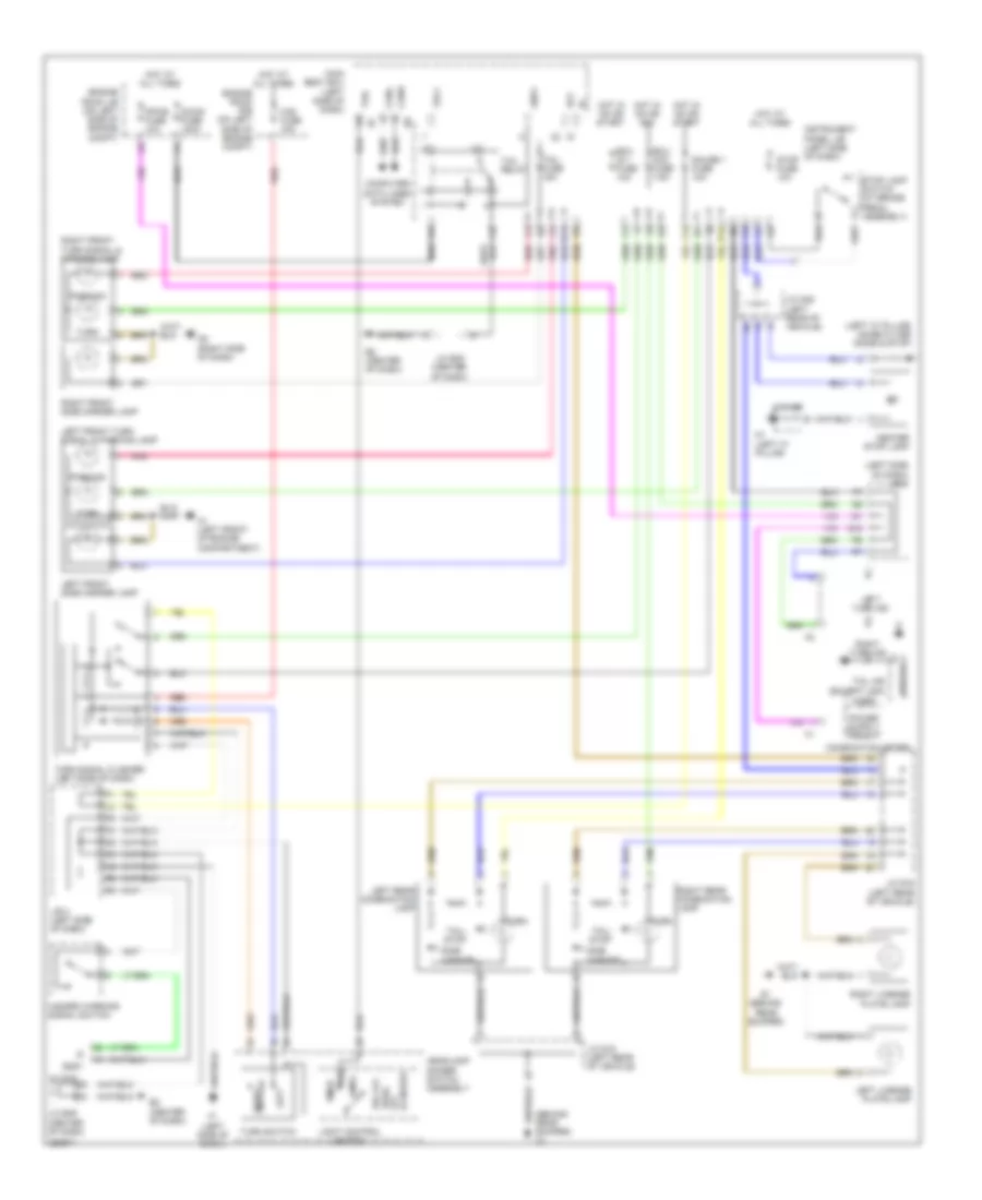
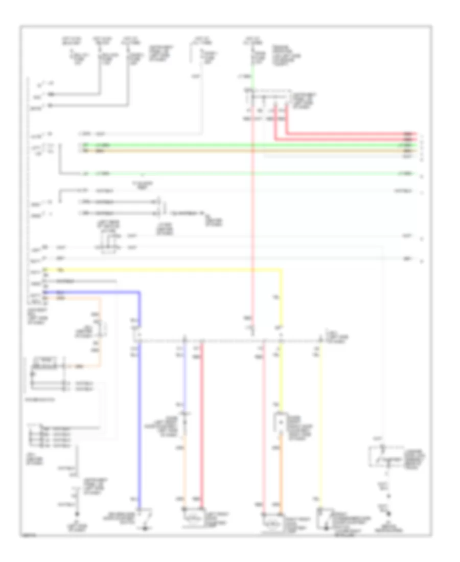
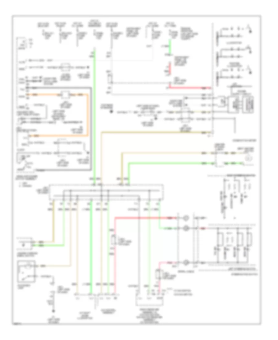
2.4L, Automatic A/C Wiring Diagram, Except Hybrid (1 of 2) for Toyota Camry CE 2007
List of elements for 2.4L, Automatic A/C Wiring Diagram, Except Hybrid (1 of 2) for Toyota Camry CE 2007:
- (behind front grille) ambient temperature sensor
- (front of engine compt) a/c pressure sensor
- (left side of dash) ion generator
- A/c amplifier (right side of dash)
- A/c blower assembly (right side of dash)
- A/c evaporator temperature sensor
- A/c fuse 2 10a
- A/c fuse 7.5a
- A58
- Blower motor (behind right side of dash)
- Blw
- Canh
- Canl
- Computer data lines system
- Connector housing color (black)
- Connector housing color (red)
- D11
- D12
- Damper servo motor (air inlet)
- Damper servo motor (air mix driver side)
- Damper servo motor (air mix front passenger side)
- Damper servo motor (air vent mode)
- E2 (center of dash)
- E3 (right side of dash)
- E38
- E40
- Engine room r/b (on left side of engine compartment)
- F16
- Gnd
- Hot at all times
- Hot in on or start
- Htr fuse 50a
- Ig+
- Instrument panel j/b (left side of dash)
- J/b 3 (left side of dash)
- J/b 4 (center of dash)
- J/c e40 & a58 (e40: right side of dash) (a58: left side of dash)
- J/c e49 (center of dash)
- L10
- L11
- L12
- Lin1
- M11
- Nca
- Pcd1
- Pnk
- Pre
- Red
- S5-3
- Sg-1
- Sg-2
- Sol+
- Tam
- Tsd
- Tsp
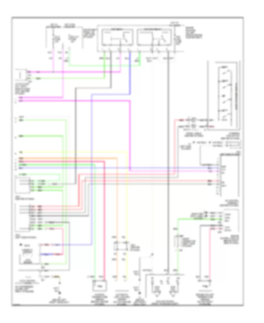
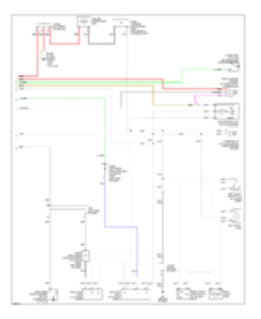
2.4L, Automatic A/C Wiring Diagram, Except Hybrid (2 of 2) for Toyota Camry CE 2007
List of elements for 2.4L, Automatic A/C Wiring Diagram, Except Hybrid (2 of 2) for Toyota Camry CE 2007:
- A/c compressor (lower left front of engine)
- A/c condenser fan motor (at front center of engine compt)
- A/c control assembly (center of dash)
- A/c room temperature sensor (behind center of dash)
- A1 (left front of engine compt)
- A24
- Ad11
- Auto
- Automatic light control sensor (on top center of dash)
- C24
- Canh
- Canl
- Cds fan fuse 40a
- Computer data lines system
- E10
- E18
- Ecu ig 1 fuse 10a
- Engine control module (left side of engine compt)
- Engine coolant temperature sensor (on top rear of engine)
- Engine room r/b (on left side of engine compartment)
- Ethw
- F1 (left side of dash)
- Fan 1 relay
- Fan 2 relay
- Fan 3 relay
- Fanh
- Fanl
- Flow control valve
- Gnd
- Hot at all times
- Hot in on or start
- Ig+
- Instrument panel j/b (left side of dash)
- J/b 3 (left side of dash)
- J/b 4 (center of dash)
- M12
- Nca
- Off
- Pnk
- Radiator fan motor (left front of engine compt)
- Rdi fan fuse 40a
- Red
- Right steering switch
- S12
- Spiral cable (center of dash)
- Steering pad switch (center of dash)
- Temp+
- Temp-
- Thw
- Tx+
2.4L, Manual A/C Wiring Diagram, Except Hybrid (1 of 2) for Toyota Camry CE 2007
List of elements for 2.4L, Manual A/C Wiring Diagram, Except Hybrid (1 of 2) for Toyota Camry CE 2007:
- (behind front grille) ambient temperature sensor
- (front of engine compt) a/c pressure sensor
- A/c 2 fuse 10a
- A/c amplifier (right side of dash)
- A/c blower assembly (right side of dash)
- A/c evaporator temperature sensor
- A/c fuse 7.5a
- A58
- Blower motor (behind right side of dash)
- Blw
- Canh
- Canl
- Computer data lines system
- Connector housing color (black)
- Connector housing color (green)
- Connector housing color (red)
- D11
- Damper servo motor (air inlet)
- Damper servo motor (air mix)
- Damper servo motor (air vent mode)
- E2 (center of dash)
- E3 (right side of dash)
- E38
- E40
- Engine room r/b (on left side of engine compartment)
- F16
- Gnd
- Hot at all times
- Hot in on or start
- Htr fuse 50a
- Ig+
- Instrument panel j/b (left side of dash)
- J/b 3 (left side of dash)
- J/c e40 & a58 (e40: right side of dash) (a58: left side of dash)
- J/c e49 (center of dash)
- Lin1
- M11
- Nca
- Pnk
- Pre
- Red
- S5-3
- Sg-2
- Sol+
- Tam
2.4L, Manual A/C Wiring Diagram, Except Hybrid (2 of 2) for Toyota Camry CE 2007
List of elements for 2.4L, Manual A/C Wiring Diagram, Except Hybrid (2 of 2) for Toyota Camry CE 2007:
- A/c compressor (lower left front of engine)
- A/c condenser fan motor (at front center of engine compt)
- A/c control assembly (center of dash)
- A1 (left front of engine compt)
- A24
- C24
- Canh
- Canl
- Cds fan fuse 40a
- Computer data lines system
- E10
- Ecu ig 1 fuse 10a
- Engine control module (left side of engine compt)
- Engine coolant temperature sensor (on top rear of engine)
- Engine room r/b (on left side of engine compartment)
- Ethw
- F1 (left side of dash)
- Fan 1 relay
- Fan 2 relay
- Fan 3 relay
- Fanh
- Fanl
- Flow control valve
- Gnd
- Hot at all times
- Hot in on or start
- Ig+
- Instrument panel j/b (left side of dash)
- J/b 3 (left side of dash)
- M12
- Pnk
- Radiator fan motor (left front of engine compt)
- Rdi fan fuse 40a
- Red
- Thw
- Tx+
3.5L
3.5L, Automatic A/C Wiring Diagram, Except Hybrid (1 of 2) for Toyota Camry CE 2007
List of elements for 3.5L, Automatic A/C Wiring Diagram, Except Hybrid (1 of 2) for Toyota Camry CE 2007:
- (front of engine compt) ambient temperature sensor
- (left side of dash) ion generator
- (right front of engine compt) a/c pressure sensor
- A/c amplifier (right side of dash)
- A/c blower assembly (right side of dash)
- A/c evaporator temperature sensor
- A/c fuse 7.5a
- A58
- Blower motor (behind right side of dash)
- Blw
- Canh
- Canl
- Computer data lines system
- Connector housing color (black)
- Connector housing color (red)
- D11
- D12
- Damper servo motor (air inlet)
- Damper servo motor (air mix driver side)
- Damper servo motor (air mix front passenger side)
- Damper servo motor (air vent mode)
- E2 (center of dash)
- E3 (right side of dash)
- E38
- E40
- Engine room r/b (on left side of engine compartment)
- Gnd
- Hot at all times
- Htr fuse 50a
- Ig+
- Instrument panel j/b (left side of dash)
- J/b 3 (left side of dash)
- J/b 4 (center of dash)
- J/c e40 & a58 (e40: right side of dash) (a58: left side of dash)
- J/c e49 (center of dash)
- L10
- L11
- L12
- Lcok
- Lin1
- M11
- Mgc
- Nca
- Pcd1
- Pnk
- Pre
- Red
- S5-3
- Sg-1
- Sg-2
- Sol+
- Tam
- Tsd
- Tsp
3.5L, Automatic A/C Wiring Diagram, Except Hybrid (2 of 2) for Toyota Camry CE 2007
List of elements for 3.5L, Automatic A/C Wiring Diagram, Except Hybrid (2 of 2) for Toyota Camry CE 2007:
- (m) m+
- (m) m-
- (s) m+
- (s) m-
- +b1
- A/c 2 fuse 10a
- A/c compressor (lower left front of engine)
- A/c control assembly (center of dash)
- A/c room temperature sensor (behind center of dash)
- A1 (behind left front headlight)
- A41
- A42
- A55
- A56
- A57
- Ad11
- Auto
- Automatic light control sensor (on top center of dash)
- C21
- C53
- C55
- Canh
- Canl
- Computer data lines system
- Cooling fan ecu (front of engine compt)
- D12
- E10
- E18
- Ecu ig 1 fuse 10a
- Engine control module (behind right side of dash)
- Engine coolant temperature sensor (on top front of engine)
- Engine room r/b (on left side of engine compartment)
- Ethw
- F1 (left side of dash)
- F16
- Fan main fuse 50a
- Fan main relay
- Flow control valve
- Gnd
- Hot at all times
- Hot in on or start
- Ig+
- Instrument panel j/b (left side of dash)
- J/b 3 (left side of dash)
- J/b 4 (center of dash)
- J/c a41 & a42 (a41: right side of dash) (a42: center of dash)
- Lock sensor
- M12
- Magnetic clutch
- Main fan motor
- Mgc relay
- Nca
- Off
- Pnk
- Red
- Rfc
- Right steering switch
- S12
- Short connector (right side of dash)
- Spiral cable (center of dash)
- Steering pad switch (center of dash)
- Sub fan motor
- Temp+
- Temp-
- Thw
- Tx+
3.5L, Manual A/C Wiring Diagram, Except Hybrid (1 of 2) for Toyota Camry CE 2007
List of elements for 3.5L, Manual A/C Wiring Diagram, Except Hybrid (1 of 2) for Toyota Camry CE 2007:
- (front of engine compt) ambient temperature sensor
- (right front of engine compt) a/c pressure sensor
- A/c amplifier (right side of dash)
- A/c blower assembly (right side of dash)
- A/c evaporator temperature sensor
- A/c fuse 7.5a
- A58
- Blower motor (behind right side of dash)
- Blw
- Canh
- Canl
- Computer data lines system
- Connector housing color (black)
- Connector housing color (green)
- Connector housing color (red)
- D11
- Damper servo motor (air inlet)
- Damper servo motor (air mix)
- Damper servo motor (air vent mode)
- E2 (center of dash)
- E3 (right side of dash)
- E38
- E40
- Engine room r/b (on left side of engine compartment)
- Gnd
- Hot at all times
- Htr fuse 50a
- Ig+
- Instrument panel j/b (left side of dash)
- J/b 3 (left side of dash)
- J/c e40 & a58 (e40: right side of dash) (a58: left side of dash)
- J/c e49 (center of dash)
- Lcok
- Lin1
- M11
- Mgc
- Nca
- Pnk
- Pre
- Red
- S5-3
- Sg-2
- Sol+
- Tam
3.5L, Manual A/C Wiring Diagram, Except Hybrid (2 of 2) for Toyota Camry CE 2007
List of elements for 3.5L, Manual A/C Wiring Diagram, Except Hybrid (2 of 2) for Toyota Camry CE 2007:
- (m) m+
- (m) m-
- (s) m+
- (s) m-
- +b1
- A/c 2 fuse 10a
- A/c compressor (lower left front of engine)
- A/c control assembly (center of dash)
- A1 (behind left front headlight)
- A41
- A42
- A55
- A56
- A57
- C21
- C53
- C55
- Canh
- Canl
- Computer data lines system
- Cooling fan ecu (front of engine compt)
- D12
- E10
- Ecu ig 1 fuse 10a
- Engine control module (behind right side of dash)
- Engine coolant temperature sensor (on top front of engine)
- Engine room r/b (on left side of engine compartment)
- Ethw
- F1 (left side of dash)
- F16
- Fan main fuse 50a
- Fan main relay
- Flow control valve
- Gnd
- Hot at all times
- Hot in on or start
- Ig+
- Instrument panel j/b (left side of dash)
- J/b 3 (left side of dash)
- J/b 4 (center of dash)
- J/c a41 & a42 (a41: right side of dash) (a42: center of dash)
- Lock sensor
- M12
- Magnetic clutch
- Main fan motor
- Mgc relay
- Pnk
- Red
- Rfc
- Short connector (right side of dash)
- Sub fan motor
- Thw
- Tx+
ANTI-LOCK BRAKES
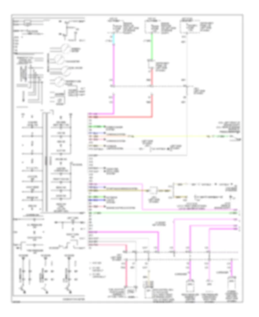
Anti-lock Brakes Wiring Diagram, Hybrid (1 of 4) for Toyota Camry CE 2007
List of elements for Anti-lock Brakes Wiring Diagram, Hybrid (1 of 4) for Toyota Camry CE 2007:
- (rear `c' pillar) junction connector o21
- +bc
- +bi1
- +bo1
- A7 (right side of dash)
- A73
- A74
- A78
- A79
- Abs main fuse 1 10a
- Abs main fuse 3 10a
- Abs mtr1 fuse 50a
- Abs mtr1 relay
- Abs mtr2 fuse 40a
- Abs mtr2 relay
- Brake stroke simulator cylinder (left rear of engine compt)
- Bs1
- Computer data lines system
- Cty
- Cty+
- Ena
- Engine room r/b (on left side of engine compt)
- Fail
- Fr+
- Fr-
- Fra+
- Fra-
- Frr+
- Frr-
- Gnd
- Gnd2
- Gnd3
- Hot at all times
- Ig1
- Left rear speed sensor (left rear hub assembly)
- Mr1
- Mtt
- Nca
- Out 1
- Out 2
- Pac1
- Pck1
- Pfr
- Pmc1
- Pnk
- Prl
- R1+
- R1-
- Red
- Right front speed sensor (at right front hub assembly)
- Rl+
- Rl-
- Rla+
- Rla-
- Rlr+
- Rlr-
- Sg1
- Short connector a78 & a79 (right side of engine compt)
- Skid control ecu with actuator (at right side of engine compt)
- Smc1
- Sp1
- Stp
- Vbz
- Vcm
- Vsc warning buzzer (left side of dash)
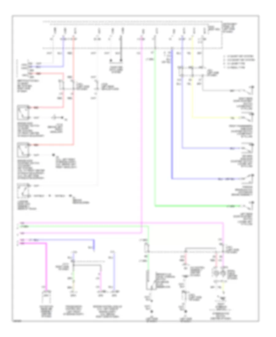
Anti-lock Brakes Wiring Diagram, Hybrid (2 of 4) for Toyota Camry CE 2007
List of elements for Anti-lock Brakes Wiring Diagram, Hybrid (2 of 4) for Toyota Camry CE 2007:
- (left side of dash)
- (left side of dash) j/b 3
- A41
- A42
- A58
- Abs ind
- Brake ind
- C13
- C6 (top rear of engine)
- Can i/f
- Combination meter
- Computer data lines system
- D10
- D13
- Dome fuse 10a
- Door courtesy switch
- E40
- Ecu ig 2 fuse 7.5a
- Ecu-b 1 fuse 10a
- Engine room j/b (on left side of engine compt)
- Engine room r/b (on left side of engine compt)
- F19
- G12
- Gauge 2 fuse 7.5a
- Hot at all times
- Hot in on or start
- Instrument panel j/b (left side of dash)
- J/b 3 (left side of dash)
- Junction connector a41 & a42 (left side of dash)
- Junction connector e40 & a58 (left side of dash)
- L12
- Micro computer
- Mpx-b fuse 10a
- O11
- O12
- Pnk
- Power
- Q12
- Red
- Slip ind
- Speedometer
- Stop fuse 10a
- Stop lamp switch (at brake pedal assembly)
- Vsc ind
- Vsc off ind
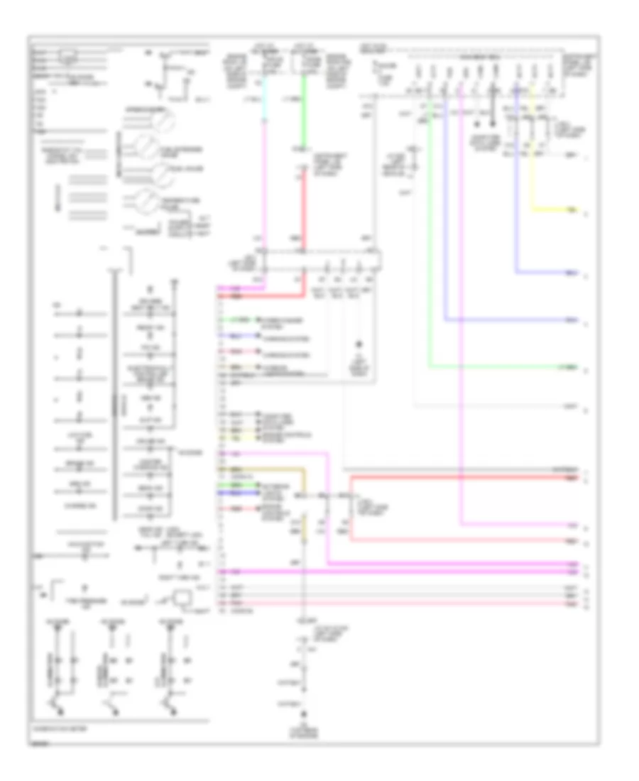
Anti-lock Brakes Wiring Diagram, Hybrid (3 of 4) for Toyota Camry CE 2007
List of elements for Anti-lock Brakes Wiring Diagram, Hybrid (3 of 4) for Toyota Camry CE 2007:
- (right front of engine compartment) a4
- A6 (right side of dash)
- Abs1 relay
- Abs2 relay
- Batt
- Bm1
- Bm2
- Brake actuator (right side of engine compt)
- Bs1
- Bs2
- Canh
- Canl
- Computer data lines system
- E2 (center of dash)
- Engine room r/b (on left side of engine compt)
- Ess
- Fla+
- Fla-
- Flr+
- Flr-
- Fra+
- Fra-
- Frr+
- Frr-
- Gnd
- Gnd1
- Gnd2
- J/b 4 (center of dash)
- Junction connector e49
- Mtt
- Pac1
- Pck1
- Pck2
- Pfl
- Pfr
- Pmc1
- Pmc2
- Prl
- Prr
- Red
- Rla+
- Rla-
- Rlr+
- Rlr-
- Rra+
- Rra-
- Rrr+
- Rrr-
- Smc1
- Smc2
- Steering sensor (on steering column)
- Vcm
- Vcm2
- Yaw rate sensor (below rear of center floor console)
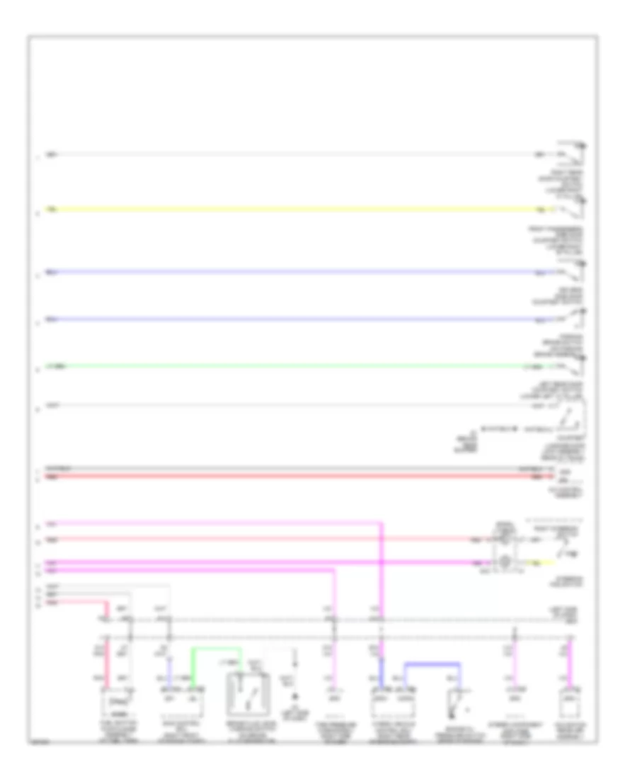
Anti-lock Brakes Wiring Diagram, Hybrid (4 of 4) for Toyota Camry CE 2007
List of elements for Anti-lock Brakes Wiring Diagram, Hybrid (4 of 4) for Toyota Camry CE 2007:
- (behind right front headlight) junction connector a44
- (on brake fluid reservoir) brake fluid level warning switch
- +bi2
- +bo2
- A3 (left side of dash)
- A75
- A76
- Abs main fuse 2 10a
- Brake pedal stroke sensor (left side of dash)
- Bs2
- Engine room r/b (on left side of engine compt)
- Fl+
- Fl-
- Fla+
- Fla-
- Flr+
- Flr-
- Gnd4
- Gnd5
- Gnd6
- Hot at all times
- Hot in on or start
- Ig2
- Ign fuse 10a
- Instrument panel j/b (left side of dash)
- Lbl
- Left front speed sensor (at left front hub assembly)
- Mr2
- Nca
- Pck2
- Pfl
- Pmc2
- Prr
- R2+
- R2-
- R4+
- Red
- Right rear speed sensor (right rear hub assembly)
- Rr+
- Rr-
- Rra+
- Rra-
- Rrr+
- Rrr-
- Sg2
- Sgsk
- Skg
- Skid control ecu (right front of engine compt)
- Sks
- Sks1
- Sks2
- Smc2
- Vcm2
- Vcsk
Anti-lock Brakes Wiring Diagram, with VSC, Except Hybrid (1 of 2) for Toyota Camry CE 2007
List of elements for Anti-lock Brakes Wiring Diagram, with VSC, Except Hybrid (1 of 2) for Toyota Camry CE 2007:
- (right front of engine compt) a4
- (right side of dash) junction connector a40 & e41
- +bm
- +bs
- A6 (right side of dash)
- Abs 1 fuse 50a
- Abs 2 fuse 30a
- C13
- Canh
- Canl
- Computer data lines system
- D/g
- D13
- Dome fuse 10a
- Engine room r/b (on left side of engine compt)
- Fl+
- Fl-
- Fr+
- Fr-
- Gnd1
- Gnd2
- Hot at all times
- Ig1
- Instrument panel j/b (left side of dash)
- Left front speed sensor (at left front hub assembly)
- Left rear speed sensor (left rear hub assembly)
- Mrf
- Pnk
- Red
- Right front speed sensor (at right front hub assembly)
- Right rear speed sensor (right rear hub assembly)
- Rl+
- Rl-
- Rr+
- Rr-
- Skid control ecu w/ actuator (at right side of engine compt)
- Sp1
- Stop fuse 10a
- Stop lamp switch (at brake pedal assembly)
- Stp 1
- Vsc 1 relay
- Vsc 2 relay
- Wfse
Anti-lock Brakes Wiring Diagram, with VSC, Except Hybrid (2 of 2) for Toyota Camry CE 2007
List of elements for Anti-lock Brakes Wiring Diagram, with VSC, Except Hybrid (2 of 2) for Toyota Camry CE 2007:
- (center of dash) junction connector e42, e43, e44, e46 & e63
- (left side of dash)
- (left side of dash) j/b 3
- Abs ind
- Batt
- Brake ind
- Can i/f
- Canh
- Canl
- Combination meter
- D10
- E2 (center of dash)
- E42
- E43
- E44
- E46
- E63
- Ecu ig 2 fuse 7.5a
- Ecu-b 1 fuse 10a
- Engine room j/b (on left side of engine compt)
- Engine room r/b (on left side of engine compt)
- Ess
- F19
- G12
- G14
- Gauge 2 fuse 7.5a
- Gnd
- Hot at all times
- Hot in on or start
- Instrument panel j/b (left side of dash)
- J/b 3 (left side of dash)
- J/b 4 (center of dash)
- Junction connector a58 & e40 (a58: left side of of dash) (e40: right side of dash)
- Junction connector e49 (center of dash)
- L12
- Main body ecu
- Micro computer
- Mpx-b fuse 10a
- P11
- Parking brake switch (lever type) (on parking brake assembly)
- Parking brake switch (pedal type) (on parking brake assembly)
- Pkb
- Pnk
- Power
- Q12
- Red
- Slip ind
- Speedometer
- Steering sensor (on steering column)
- Vsc ind
- Vsc off ind
- Vsc warning buzzer (left side of dash)
- Yaw rate sensor (below rear of center floor console)
Anti-lock Brakes Wiring Diagram, without VSC, Japan Production, Except Hybrid for Toyota Camry CE 2007
List of elements for Anti-lock Brakes Wiring Diagram, without VSC, Japan Production, Except Hybrid for Toyota Camry CE 2007:
- (j/c j43: center of dash) j/c 43 & 44
- (right side of dash) a6
- +bm
- +bs
- A4 (right front of engine compt)
- A58
- Abs 1 fuse 50a
- Abs 2 fuse 30a
- Abs ind
- Brake ind
- C13
- Canh
- Canl
- Combination meter
- Computer data lines system
- D13
- E40
- E43
- E44
- Ecu-ig 2 fuse 7.5a
- Engine room j/b (on left side of engine compt)
- Engine room r/b (on left side of engine compt)
- F1 (left side of dash)
- F19
- F7 red
- Fl+
- Fl-
- Fr+
- Fr-
- G14
- Gauge 2 fuse 7.5a
- Gnd1
- Gnd2
- Hot at all times
- Hot in on or start
- Ig1
- Instrument panel j/b (left side of dash)
- J/b 3 (left side of dash)
- J/b 4 (center of of dash)
- J/c 40 & 58 (j/c e40: right side of dash) (j/c a58: left side of dash)
- L12
- Left front speed sensor (at left front hub assembly)
- Left rear speed sensor (left rear hub assembly)
- Main body ecu
- Micro computer
- Mpx-8 fuse 10a
- P11
- Parking brake switch (lever type) (on parking brake assembly)
- Parking brake switch (pedal type) (on parking brake assembly)
- Pkb
- Pnk
- Power
- Q12
- Red
- Right front speed sensor (at right front hub assembly)
- Right rear speed sensor (right rear hub assembly)
- Rl+
- Rl-
- Rr+
- Rr-
- Skid control ecu w/ actuator (at right side of engine compt)
- Sp1
- Stop fuse 10a
- Stop lamp switch
- Stp1
- Vsc warning buzzer (left side of dash)
Anti-lock Brakes Wiring Diagram, without VSC, USA Production, Except Hybrid for Toyota Camry CE 2007
List of elements for Anti-lock Brakes Wiring Diagram, without VSC, USA Production, Except Hybrid for Toyota Camry CE 2007:
- (j/c j43: center of dash) j/c 43 & 44
- (right side of dash) a6
- +bm
- +bs
- A4 (right front of engine compt)
- A58
- Abs 1 fuse 50a
- Abs 2 fuse 30a
- Abs ind
- Brake ind
- C13
- Canh
- Canl
- Combination meter
- Computer data lines system
- D13
- Dome fuse 10a
- E40
- E43
- E44
- Ecu-ig 2 fuse 7.5a
- Engine room j/b (on left side of engine compt)
- Engine room r/b (on left side of engine compt)
- F1 (left side of dash)
- F7 red
- Fl+
- Fl-
- Fr+
- Fr-
- G14
- Gauge 2 fuse 7.5a
- Gnd1
- Gnd2
- Hot at all times
- Hot in on or start
- Ig1
- Instrument panel j/b (left side of dash)
- J/b 3 (left side of dash)
- J/c 40 & 58 (j/c e40: right side of dash) (j/c a58: left side of dash)
- L12
- Left front speed sensor (at left front hub assembly)
- Left rear speed sensor (left rear hub assembly)
- Main body ecu
- Micro computer
- Mpx-8 fuse 10a
- P11
- Parking brake switch (lever type) (on parking brake assembly)
- Parking brake switch (pedal type) (on parking brake assembly)
- Pkb
- Pnk
- Power
- Q12
- Red
- Right front speed sensor (at right front hub assembly)
- Right rear speed sensor (right rear hub assembly)
- Rl+
- Rl-
- Rr+
- Rr-
- Skid control ecu w/ actuator (at right side of engine compt)
- Sp1
- Stop fuse 10a
- Stop lamp switch
- Stp
ANTI-THEFT
Forced Entry Wiring Diagram, Except Hybrid with Smart Key System (1 of 4) for Toyota Camry CE 2007
List of elements for Forced Entry Wiring Diagram, Except Hybrid with Smart Key System (1 of 4) for Toyota Camry CE 2007:
- (left side of dash) j/b 3
- Acc
- Act+
- Act-
- Actd
- Altb
- Batb
- Becu
- Canh
- Canl
- Cann
- Canp
- D10
- D11
- D16
- Dcty
- Dome fuse 10a
- Door 1 fuse 25a
- Door 2 fuse 25a
- Driver's side door courtesy switch (lower left "b" pillar)
- E2 (center of dash)
- Ecu-acc fuse 7.5a
- Ecu-b 1 fuse 10a
- Ecu-ig 1 fuse 10a
- Engine room r/b (on left side of engine compt)
- Exterior lights system
- F10
- F18
- Front passenger's side door courtesy switch (lower right "b" pillar)
- G12
- Gauge 1 fuse 10a
- Gauge 2 fuse 7.5a
- Gnd1
- Gnd2
- Gnd3
- H16
- Haz
- Headlights system
- Horn
- Horns system
- Hot at all times
- Hot in on or acc
- Hot in on or start
- Hrly
- I10
- Ign fuse 10a
- Ile
- Inds
- Indw
- Instrument panel j/b (left side of dash)
- Interior lights system
- J/b 3 (left side of dash)
- J/c 28 (left rear vehicle floor)
- J/c 49 (center of dash)
- K12
- K15
- K16
- K7 k7
- Lcty
- Left rear door courtesy switch (lower left "c" pillar)
- Lgcy
- Lin1
- Lock
- Lswd
- Lswl
- Lswp
- Lswr
- Luggage compt door lock cylinder (in luggage compt)
- Luggage door lock assembly (rear of trunk)
- M13
- Main body ecu (left side of dash)
- O12
- P11
- Pcty
- Pnk
- Power window master switch
- Rcty
- Red
- Right rear door courtesy switch (lower right "c" pillar)
- S1 (behind rear bumper)
- Ssw1
- Ssw2
- Swil
- Tr+
- Tsw
- Ul1
- Ul2
- Ul3
- Unlock
Forced Entry Wiring Diagram, Except Hybrid with Smart Key System (2 of 4) for Toyota Camry CE 2007
List of elements for Forced Entry Wiring Diagram, Except Hybrid with Smart Key System (2 of 4) for Toyota Camry CE 2007:
- (behind right side of dash)
- (right rear vehicle floor) j/c 29
- +b (dome)
- C55
- Can i/f
- Canh canl a55
- Combination meter
- Door lock control switch
- Drive ic
- Driver's side door lock assembly (in left front door)
- E2 (center of dash)
- E41
- E42
- E43
- E44
- Engine control module
- Front passenger's side door lock assembly (in right front door)
- J/b 3 (left side of dash)
- J/c 21 (right "c" pillar)
- J/c 40 & 41 (right side of dash) a40
- J/c 42, 43 & 44 (j/c 42 & 43: center of dash)
- Left rear door lock assembly (in left rear door)
- Lock
- Lock key
- Micro computer
- Multi lcd
- Park/neutral position switch (on transaxle)
- Pnk
- Red
- Right rear door lock assembly (in right rear door)
- Unlock
- Unlock key
- Warning ind master
Forced Entry Wiring Diagram, Except Hybrid with Smart Key System (3 of 4) for Toyota Camry CE 2007
List of elements for Forced Entry Wiring Diagram, Except Hybrid with Smart Key System (3 of 4) for Toyota Camry CE 2007:
- (center of dash) j/b 4
- (left side of dash) instrument panel j/b
- 11l
- 12a
- 12c
- 12f
- A41
- A42
- Ant1
- Ant2
- Clg
- Clgb
- D11
- D13
- E1 (left side of dash)
- E11
- Efi 1 fuse 10a
- Engine hood courtesy switch (at front center of radiator support)
- Engine room j/b (on left side of engine compt)
- G10
- G11
- Gnd
- H12
- Hot at all times
- Instrument panel j/b (left side of dash)
- J/b 3 (left side of dash)
- J/b 4 (center of dash)
- J/b 4 (center of dash)
- J/c 41 & 42 (j/c a41: right side of dash) (j/c a42: center of dash)
- J/c 43 (center of dash)
- J10
- L12
- Pnk
- Power switch
- Red
- Right front door electrical key oscillator (right front door)
- Right front door outside handle
- S-horn fuse 7.5a
- Security horn (right rear of engine compt)
- Security horn relay
- Sel
- Sens
- Sgt
- Ss1
- Ss2
- Trg+
- Trg-
Forced Entry Wiring Diagram, Except Hybrid with Smart Key System (4 of 4) for Toyota Camry CE 2007
List of elements for Forced Entry Wiring Diagram, Except Hybrid with Smart Key System (4 of 4) for Toyota Camry CE 2007:
- "c" pillar)
- (behind rear bumper) outside luggage room electrical key oscillator
- (behind rear bumper) s1
- (center of dash) j/c 49
- (front of center console) console electrical key oscillator
- (left side of dash) f1
- (near rear seat assembly) rear seat electrical key oscillator
- (right side of luggage compt) inside luggage room electrical key oscillator
- A3 (left side of dash)
- Acc
- Agnd
- Ant
- Ant1
- Ant2
- Asel
- Bzr
- Canh
- Canl
- Certification ecu (right side of dash)
- Cg2b
- Cg5b
- Cg6b
- Cg7b
- Cg8b
- Cgib
- Clg
- Clg1
- Clg2
- Clg3
- Clg4
- Clg5
- Clg6
- Clg7
- Clg8
- Clgb
- Clock
- Code
- Data
- Door control receiver (at right
- E2 (center of dash)
- E58
- E59
- Electrical key antenna (right rear of luggage compt)
- F11
- Gnd
- Gnd1
- Hsw
- Ind
- J/b 3 (left side of dash)
- J/b 4 (center of dash)
- J/c 21 (right "c" pillar)
- Left front door electrical key oscillator (left front door)
- Left front door outside handle
- Lin
- Luggage electrical key switch (center of trunk lid)
- Pnk
- R11
- Rc0
- Rda
- Red
- Rssi
- Security indicator
- Sel
- Sel1
- Sel2
- Sen1
- Sen2
- Sens
- Sgt
- Sh-
- Trg+
- Trg-
- Tsw1
- Tsw2
- Tsw5
- Txct
- Vc5
- Wireless door lock buzzer (in engine compt, behind left front headlamp)
Forced Entry Wiring Diagram, Except Hybrid without Smart Key System (1 of 2) for Toyota Camry CE 2007
List of elements for Forced Entry Wiring Diagram, Except Hybrid without Smart Key System (1 of 2) for Toyota Camry CE 2007:
- (center of dash) e2
- (left side of dash) j/b 3
- (right "c" pillar) j/c 21
- A2 (2.4l: left front of engine compt) (3.5l: behind left front headlight)
- Acc
- Act+
- Act-
- Actd
- Altb
- Becu
- Bzr
- Canh
- Canl
- Clock
- D10
- D11
- D16
- Dcty
- Door 1 fuse 25a
- Door control receiver (at right "c" pillar)
- Driver's side door courtesy switch (lower left "b" pillar)
- Ecu-acc fuse 7.5a
- Ecu-b 1 fuse 10a
- Ecu-ig 1 fuse 10a
- Engine hood courtesy switch (2.4l: on left side of radiator support) (3.5l: at front center of radiator support)
- Engine room r/b (on left side of engine compt)
- Exterior lights system
- F1 (left side
- F10
- F18
- Front passenger's side door courtesy switch (lower right "b" pillar)
- G12
- Gauge 1 fuse 10a
- Gauge 2 fuse 7.5a
- Gnd1
- Gnd2
- H16
- Haz
- Hcty
- Headlights system
- Horn
- Horns system
- Hot at all times
- Hot in on or acc
- Hot in on or start
- Hrly
- I10
- Ile
- Ind
- Instrument panel j/b (left side of dash)
- Interior lights system
- J/b 3 (left side of dash)
- J/b 3 (left side of dash) red
- J/c 28 (left rear vehicle floor)
- J/c 49 (center of dash)
- K12
- K15
- K16
- Ksw
- Lcty
- Left rear door courtesy switch (lower left "c" pillar)
- Lgcy
- Lsr
- Lswd
- Lswp
- Luggage compartment door lock cylinder (in luggage compt)
- Luggage door lock assembly (rear of trunk)
- Main body ecu (left side of dash)
- O12
- Of dash)
- P11
- Pcty
- Pnk
- Prg
- R11
- Rcty
- Rda
- Rda pnk
- Red
- Right rear door courtesy switch (lower right "c" pillar)
- S1 (behind rear bumper)
- Security indicator
- Tr+
- Trly
- Tsw
- Ul1
- Ul2
- Ul3
Forced Entry Wiring Diagram, Except Hybrid without Smart Key System (2 of 2) for Toyota Camry CE 2007
List of elements for Forced Entry Wiring Diagram, Except Hybrid without Smart Key System (2 of 2) for Toyota Camry CE 2007:
- (left side
- +b (dome)
- 2.4l
- 3.5l
- A40
- Can i/f
- Canh canl a24
- Canh canl a55
- Combination meter
- Door unlock
- Drive ic
- Driver's side door lock assembly (in left front door)
- E2 (center of dash)
- E41
- E42
- E43
- E44
- Engine control module (behind right side of dash)
- Engine control module (left side of engine compt)
- Front passenger's side door lock assembly (in right front door)
- J/b 3 (left side of dash)
- J/c 21 (right "c" pillar)
- J/c 29 (right rear vehicle floor)
- J/c 40 & 41 (right side of dash)
- J/c 42, 43 & 44 (j/c 42 & 43: center of dash)
- J/c 49 (center of dash)
- Left rear door lock assembly (in left rear door)
- Lock
- Lock control switch
- Lock key
- Master warning ind
- Micro computer
- Multi lcd
- Of dash) a3
- P c24
- P c55
- Park/neutral position switch (on transaxle)
- Power window master switch
- Red
- Right rear door lock assembly (in right rear door)
- Unlock
- Unlock key
- Unlock warning switch (lower left side of dash)
- Wireless door lock buzzer (in engine compt, behind left front headlamp)
Forced Entry Wiring Diagram, Hybrid (1 of 4) for Toyota Camry CE 2007
List of elements for Forced Entry Wiring Diagram, Hybrid (1 of 4) for Toyota Camry CE 2007:
- (left side of dash) j/b 3
- Acc
- Act+
- Act-
- Actd
- Altb
- Am1
- Am2
- Am2 fuse 7.5a
- Batb
- Canh
- Canl
- Cann
- Canp
- Computer data lines system
- D11
- D16
- Dcty
- Dome fuse 10a
- Door 1 fuse 25a
- Door 2 fuse 25a
- Driver's side door courtesy switch
- E12
- E2 (center of dash)
- Ecu-acc fuse 7.5a
- Ecu-ig 1 fuse 10a
- Engine room r/b (on left side of engine compt)
- Exterior lights system
- F10
- F18
- Front passenger's side door courtesy switch (lower right "b" pillar)
- G12
- Gauge 2 fuse 7.5a
- Gnd1
- Gnd2
- Gnd3
- Haz
- Headlights system
- Horn
- Horns system
- Hot at all times
- Hot in on or acc
- Hot in on or start
- Hrly
- Ign fuse 10a
- Ile
- Inds
- Indw
- Instrument panel j/b (left side of dash)
- Interior lights system
- J/b 3 (left side of dash)
- J/b 4 (center of dash)
- J/c e49 (center of dash)
- J/c n28 (left rear of vehicle)
- K12
- K15
- K16
- Lcty
- Left rear door courtesy switch (lower left "c" pillar)
- Lgcy
- Lin1
- Lock
- Lswd
- Lswl
- Lswp
- Lswr
- Luggage door lock assembly (rear of trunk)
- M10
- M12
- M16
- Main body ecu (left side of dash)
- O12
- P11
- Pcty
- Pnk
- Power window master switch
- Rcty
- Rdy
- Red
- Right rear door courtesy switch (lower right "c" pillar)
- S1 (behind rear bumper)
- Spd
- Ssw1
- Ssw2
- Stsw
- Swil
- Tr+
- Ul1
- Ul3
- Unlock
Forced Entry Wiring Diagram, Hybrid (2 of 4) for Toyota Camry CE 2007
List of elements for Forced Entry Wiring Diagram, Hybrid (2 of 4) for Toyota Camry CE 2007:
- (right rear of engine compt) hybrid vehicle control ecu
- +b(dome)
- +bs
- A61
- Buzzer
- C64
- Can h
- Can i/f
- Can l
- Combination meter
- Computer data lines system
- Door lock control switch
- Drive ic
- Driver's side door lock assembly (in driver's door)
- F1 (left side of dash)
- Front passenger's side door lock assembly (in right front door)
- Ig2
- J/b 3 (left side of dash)
- J/c n29
- J/c o21 (rear "c" pillar)
- Left rear door lock assembly (in left rear door)
- Lock
- Lock key
- Micro computer
- Multi lcd
- N1 (left "c" pillar)
- Park/neutral position switch (on transaxle)
- Pnk
- Rdy
- Ready ind
- Red
- Right rear door lock assembly (in right rear door)
- St2
- Unlock
- Unlock key
- Warning ind master
Forced Entry Wiring Diagram, Hybrid (3 of 4) for Toyota Camry CE 2007
List of elements for Forced Entry Wiring Diagram, Hybrid (3 of 4) for Toyota Camry CE 2007:
- (left side of dash)
- (left side of dash) instrument panel j/b
- A12
- Ant1
- Ant2
- Antenna coil
- C12
- Clg
- Clgb
- D13
- E1 (left side of dash)
- E11
- Efi 1 fuse 10a
- Engine room j/b (on left side of engine compt)
- F12
- G10
- G11
- Gnd
- H12
- Hot at all times
- Instrument panel j/b
- J/b 3 (left side of dash)
- J/b 4 (center of dash)
- L11
- L12
- Pnk
- Power switch
- Red
- Right front door electrical key oscillator (right front door)
- Right front door outside handle
- Sel
- Sens
- Sgt
- Ss1
- Ss2
- Trg+
- Trg-
Forced Entry Wiring Diagram, Hybrid (4 of 4) for Toyota Camry CE 2007
List of elements for Forced Entry Wiring Diagram, Hybrid (4 of 4) for Toyota Camry CE 2007:
- (behind rear bumper) outside luggage room electrical key oscillator
- (behind rear bumper) s1
- (center of dash) j/c e49
- (center of trunk lid) luggage electrical key switch
- (front of center console) console electrical key oscillator
- (left side of dash) e1
- (left side of dash) f1
- (near rear seat assembly) rear seat electrical key oscillator
- (right side of luggage compt) inside luggage room electrical key oscillator
- A3 (left side of dash)
- Acc
- Agnd
- Ant
- Ant1
- Ant2
- Asel
- Bzr
- Canh
- Canl
- Certification ecu (right side of dash)
- Cg2b
- Cg5b
- Cg6b
- Cg7b
- Cg8b
- Cgib
- Clg
- Clg1
- Clg2
- Clg3
- Clg4
- Clg5
- Clg6
- Clg7
- Clg8
- Clgb
- Clock
- Code
- Data
- Door control receiver (at right "c" pillar)
- E2 (center of dash)
- Electrical key antenna (right rear of luggage compt)
- F11
- Gnd
- Gnd1
- Ind
- J/b 3 (left side of dash)
- J/b 4 (center of dash)
- J/c a42 (left side of dash)
- J/c o21 (rear "c" pillar)
- Left front door electrical key oscillator (left front door)
- Left front door outside handle
- Lin
- Nca
- Pnk
- R11
- Rc0
- Rda
- Red
- Rssi
- Security ind
- Sel
- Sel1
- Sel2
- Sen1
- Sen2
- Sens
- Sgt
- Trg+
- Trg-
- Tsw1
- Tsw2
- Tsw5
- Txct
- Vc5
- Wireless door lock buzzer (in engine compt, behind left front headlamp)
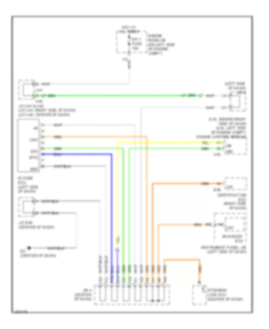
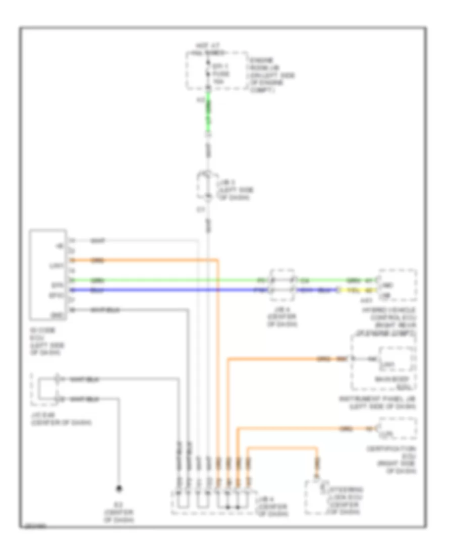
Immobilizer Wiring Diagram, Except Hybrid with Smart Key System for Toyota Camry CE 2007
List of elements for Immobilizer Wiring Diagram, Except Hybrid with Smart Key System for Toyota Camry CE 2007:
- (3.5l: behind right side of dash) (2.4l: left side of engine compt) engine control module
- (left side of dash) j/b 3
- A41
- A42
- A55
- C11
- Certification ecu (right side of dash)
- E2 (center of dash)
- E58
- Efi 1 fuse 10a
- Efii
- Efio
- Engine room j/b (on left side of engine compt)
- F10
- Gnd
- Hot at all times
- Id code ecu (left side of dash)
- Imi
- Imo
- Instrument panel j/b (left side of dash)
- J/b 4 (center of dash)
- J/c a41 & a42 (j/c a41: right side of dash) (j/c a42: center of dash)
- J/c e49 (center of dash)
- Lin
- Lin1
- Main body ecu
- Steering lock ecu (center of dash)
Immobilizer Wiring Diagram, Except Hybrid without Smart Key System for Toyota Camry CE 2007
List of elements for Immobilizer Wiring Diagram, Except Hybrid without Smart Key System for Toyota Camry CE 2007:
- (left side of dash) j/b 3
- (lower left "b" pillar) driver's side door courtesy switch
- A12
- A24
- A41
- A42
- Agnd
- Clock
- Code
- Computer data lines system
- Cty
- E2 (center of dash)
- Efi 1 fuse 10a
- Efii
- Efio
- Engine control module (2.4l: left side of engine compt) (3.5l: behind right side of dash)
- Engine room j/b (on left side of engine compt)
- F1 (left side of dash)
- Gnd
- Hot at all times
- Hot in on or start
- Ign fuse 10a
- Imi
- Imo
- Ind
- Instrument panel j/b (left side of dash)
- J/c a41 & a42 (j/c a41: right side of dash) (j/c a42: center of dash)
- J/c e49 (center of dash)
- Ksw
- M13
- O12
- Pnk
- R11
- Red
- Security indicator
- Transponder key amplifier (in steering column)
- Transponder key coil
- Transponder key ecu (left side of dash)
- Txct
- Unlock warning switch (lower left side of dash)
- Vc5
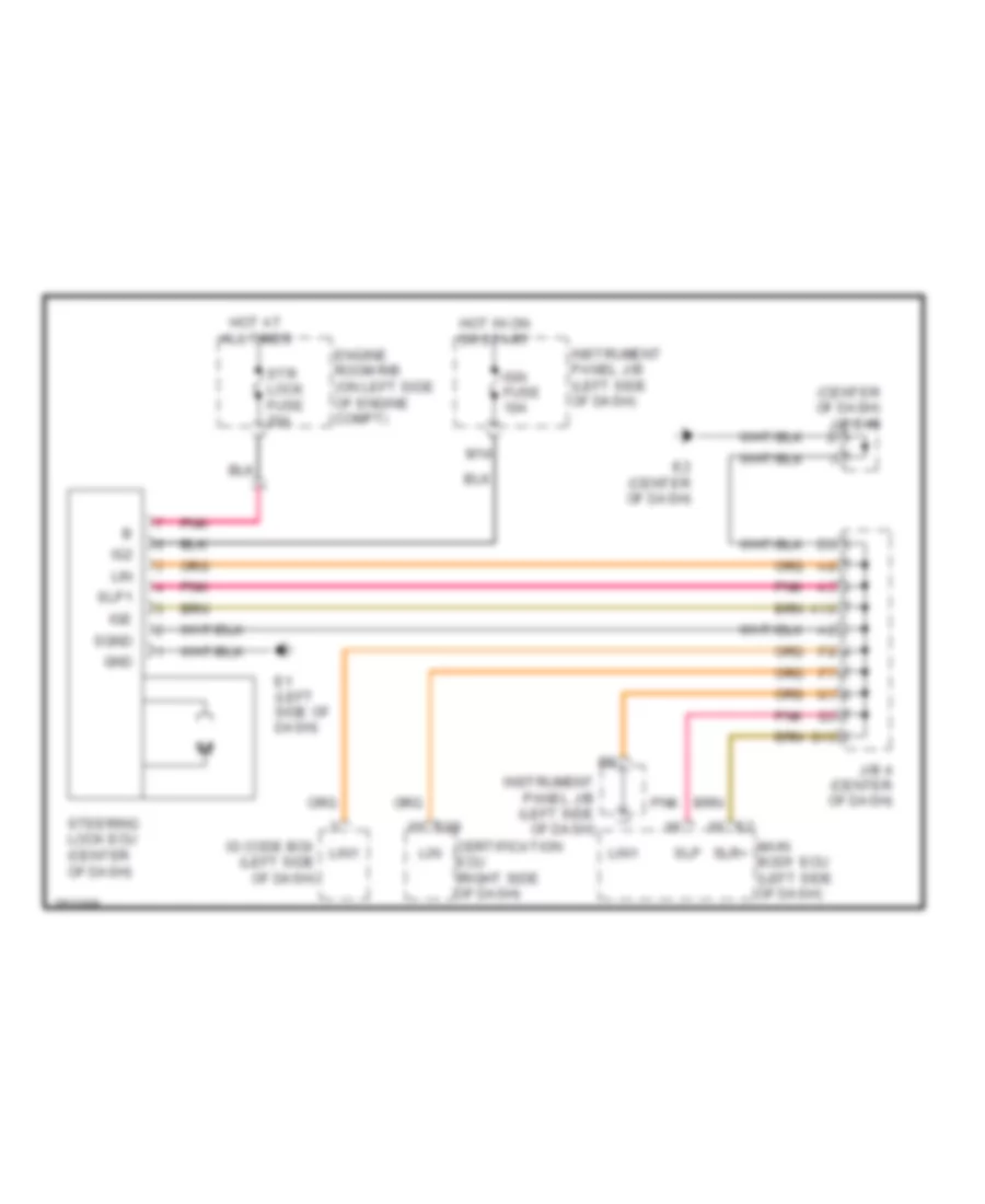
Immobilizer Wiring Diagram, Hybrid for Toyota Camry CE 2007
List of elements for Immobilizer Wiring Diagram, Hybrid for Toyota Camry CE 2007:
- A61
- C11
- Certification ecu (right side of dash)
- E2 (center of dash)
- Efi 1 fuse 10a
- Efii
- Efio
- Engine room j/b (on left side of engine compt)
- F10
- Gnd
- Hot at all times
- Hybrid vehicle control ecu (right rear of engine compt)
- Id code ecu (left side of dash)
- Imi
- Imo
- Instrument panel j/b (left side of dash)
- J/b 3 (left side of dash)
- J/b 4 (center of dash)
- J/c e49 (center of dash)
- Lin
- Lin1
- Main body ecu
- Steering lock ecu (center of dash)
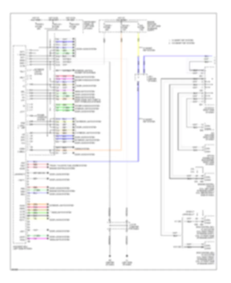
BODY CONTROL MODULES
Body Control Modules Wiring Diagram, Except Hybrid (1 of 2) for Toyota Camry CE 2007
List of elements for Body Control Modules Wiring Diagram, Except Hybrid (1 of 2) for Toyota Camry CE 2007:
- 2.4l
- 3.5l
- A/c amplifier (right side of dash)
- A24
- A26
- A40
- A55
- A60
- Acan
- Acc
- Accr
- Act+
- Act-
- Altb
- Am2
- Am2 fuse 7.5a
- Batb
- Becu
- C14
- Can+
- Can-
- Canh
- Canl
- Cltb
- Clte
- Clts
- D10
- D11
- D16
- Door 1 fuse 25a
- Door 2 fuse 25a
- Door locks system
- Drl
- E12
- E2 (center of dash)
- E38
- E41
- Ecu-acc fuse 7.5a
- Ecu-b 1 fuse 10a
- Ecu-ig 1 fuse 10a
- Engine control module (2.4l: left side of engine compt) (3.5l: behind right side of dash)
- Engine controls system
- Engine room r/b (on left side of engine compt)
- Exterior lights system
- F1 (left side of dash)
- F10
- F18
- Ffog
- G12
- Gnd1
- Gnd2
- Head
- Headlights system
- Headlights system door locks, anti-theft & shift interlock systems
- Horn
- Horns system
- Hot at all times
- Hot in on or acc
- Hot in on or start
- Hrly
- I10
- Ig2d
- Ile
- Instrument panel j/b (left side of dash)
- Interior lights & power top systems
- Interior lights system
- J/b 4 (center of dash)
- J/c 40 & 41 (right side of dash)
- J/c 49 (center of dash)
- Japan built
- K12
- K15
- K16
- Lcty
- Lgcy
- Lin1
- Lswl lsr
- Lswp
- Lswr/rcty
- M12
- Main body ecu (left side of dash)
- Option connector (bus buffer) (right side of dash)
- P11
- Pcty
- Pkb
- Pnk
- Power windows system
- Prg
- Rcty
- Rda
- Red
- Skid control ecu w/ actuator (2.4l: right front of engine compt) (3.5l: at right side of engine compt)
- Stp
- Trly
- Trunk, tailgate, fuel doors system
- Tsw
- Ul1
- Ul2
- Us built
- W/ smart key system
- W/ vsc
- W/o smart key system
- W/o vsc
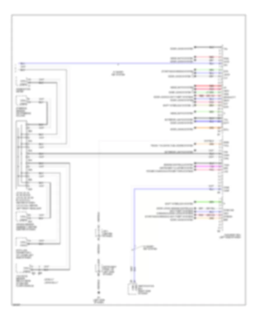
Body Control Modules Wiring Diagram, Except Hybrid (2 of 2) for Toyota Camry CE 2007
List of elements for Body Control Modules Wiring Diagram, Except Hybrid (2 of 2) for Toyota Camry CE 2007:
- (j/c 43 (3.5l): behind
- Actd
- Air bag sensor assembly center (center of dash)
- Am1
- Bzr
- Canh
- Canl
- Cann
- Canp
- Center of dash)
- Certification ecu (right side of dash)
- Combination meter
- Data link connector 3 (at lower left side of dash)
- Dcty
- Door locks & anti-theft systems
- Door locks system
- Door locks, engine controls & anti-theft systems warning & door locks systems
- E1 (left side of dash)
- E30
- E34
- E42
- E43
- E44
- E45
- E46
- E62
- E63
- E65
- Engine controls system
- Exterior lights system
- Ffgo
- G10
- Gnd3
- Haz
- Headlights system
- Inds
- Indw
- Instrument cluster system
- Instrument panel j/b (left side of dash)
- J/b 4 (center of dash)
- J/c 42, 43, 44, 45, 46, 62 & 63 (j/c 42, 45, 46, 62, 63 & 43 (2.4l):
- Japan built
- Ksw
- Left front headlamp)
- Lin2
- Lswd
- Main body ecu (left side of dash)
- Pnk
- Power windows & power tops systems
- Red
- Shift interlock system
- Slp
- Slr+
- Spd
- Ssw1
- Ssw2/hcty
- Starting/charging & anti-theft systems
- Starting/charging system
- Steering sensor (on steering column)
- Str
- Str2/sh
- Stsw/ind
- Swil
- Tach
- Tail
- Tkul
- Tr+
- Trunk, tailgate, fuel doors system
- Ul3
- Us built
- W/ smart key system
- Yaw rate sensor (below rear of center floor console)
Body Control Modules Wiring Diagram, Hybrid (1 of 2) for Toyota Camry CE 2007
List of elements for Body Control Modules Wiring Diagram, Hybrid (1 of 2) for Toyota Camry CE 2007:
- A/c amplifier (right side of dash)
- A40
- A41
- A42
- A61
- A66
- A74
- Acan
- Acc
- Act+
- Act-
- Altb
- Am2
- Am2 fuse 7.5a
- Batb
- C14
- Can+
- Can-
- Canh
- Canl
- Cltb
- Clte
- Clts
- D11
- D16
- Door 1 fuse 25a
- Door 2 fuse 25a
- Door locks system
- Door locks, anti-theft & shift interlock systems
- Drl
- E12
- E2 (center of dash)
- E38
- E41
- Ecu-acc fuse 7.5a
- Ecu-ig 1 fuse 10a
- Engine controls system
- Engine room r/b (on left side of engine compt)
- Exterior lights system
- F1 (left side of dash)
- F10
- F12
- F18
- G12
- Gnd1
- Gnd2
- Head
- Headlights system
- Horn
- Horns system
- Hot at all times
- Hot in on or acc
- Hot in on or start
- Hrly
- Hybrid vehicle control ecu (right rear of engine compt)
- Ig2d
- Ile
- Instrument panel j/b (left side of dash)
- Interior lights system
- J/b 3 (left side of dash)
- J/b 4 (center of dash)
- J/c a40 & e41 (right side of dash)
- J/c a41 & a42 (left side of dash)
- J/c e49 (center of dash)
- K12
- K15
- K16
- Lcty
- Lgcy
- Lin1
- Lswl
- Lswp
- Lswr
- M12
- Main body ecu (left side of dash)
- Navigation receiver assembly (if equipped)
- Nca
- Option connector (bus buffer) (right side of dash)
- P11
- Pcty
- Pkb
- Pnk
- Power steering ecu (left rear of engine compt)
- Power windows system
- Rcty
- Skid control ecu (right front of engine compt)
- Stp
- Trly
- Ul1
Body Control Modules Wiring Diagram, Hybrid (2 of 2) for Toyota Camry CE 2007
List of elements for Body Control Modules Wiring Diagram, Hybrid (2 of 2) for Toyota Camry CE 2007:
- Actd
- Air bag sensor assembly center (center of dash)
- Am1
- Canh
- Canl
- Cann
- Canp
- Certification ecu (right side of dash)
- Combination meter
- Data link connector 3 (at lower left side of dash)
- Dcty
- Door locks system
- E1 (left side of dash)
- E30
- E42
- E43
- E44
- E45
- E46
- E62
- E63
- E70
- E71
- Engine controls system
- Exterior lights system
- G10
- Gnd3
- Haz
- Headlights system
- Inds
- Indw
- Instrument cluster system
- Instrument panel j/b (left side of dash)
- J/b 4 (center of dash)
- J/c e42, e43, e44, e45, e46, e62 & e63 (center of dash)
- J/c e69 (center of dash)
- Lin2
- Lswd
- Main body ecu (left side of dash)
- Nca
- Pnk
- Power tops system
- Rdy
- Red
- Shift interlock system
- Short connector e70 & e71 (right side of dash)
- Slp
- Slr+
- Spd
- Ssw1
- Ssw2
- Steering sensor (on steering column)
- Stsw
- Swil
- Tail
- Tcan
- Tr+
- Trunk, tailgate, fuel doors system
- Ul3
- Yaw rate sensor (below rear of center floor console)
COMPUTER DATA LINES
Computer Data Lines Wiring Diagram, Except Hybrid for Toyota Camry CE 2007
List of elements for Computer Data Lines Wiring Diagram, Except Hybrid for Toyota Camry CE 2007:
- (2.4l)
- (3.5l)
- (at lower left side of dash) data link connector 3
- (center of dash) e2
- (center of dash) j/c 49
- (j/c 43 (3.5l): behind left front headlamp) (j/c 43 (2.4l): center of dash) (j/c 42, 45, 46, 62 & 63: center of dash) j/c 42, 43, 44, 45, 46, 62 & 63
- (left side of dash) main body ecu
- (rear of engine compt) j/c 57
- (top rear of engine) (2.4l) c6
- A/c amplifier (right side of dash)
- A24
- A25
- A26
- A40
- A41
- A42
- A55
- A60
- Air bag sensor assembly center (center of dash)
- Bat
- C10
- C55
- Can+
- Can-
- Canh
- Canl
- Cann
- Canp
- Certification ecu (w/ smart key) (right side of dash)
- Combination meter
- D/g
- D10
- Dia
- E10
- E30
- E34
- E38
- E41
- E42
- E43
- E44
- E45
- E46
- E58
- E62
- E63
- E65
- Engine control module (2.4l: left side of engine compt) (3.5l: behind right side of dash)
- H11
- Hot at all times
- Instrument panel j/b (left side of dash)
- J/b 3 (left side of dash)
- J/b 4 (center of dash)
- J/c 40 & 41 (right side of dash)
- J/c 41 & 42 (3.5l) (j/c 41: right side of dash) (j/c 42: center of dash)
- Japan built
- M12
- Obd fuse 7.5a
- Occupant classification ecu (in front passenger's seat)
- Option connector (bus buffer) (right side of dash)
- Pnk
- Sil
- Skid control ecu w/ actuator (2.4l: right front of engine compt) (3.5l: at right side of engine compt)
- Steering sensor (on steering column)
- T10
- Tac
- Tach
- Tire pressure warning ecu (right side of dash)
- Transmission control ecu (3.5l) (left front of engine compt)
- Transponder key ecu (w/o smart key) (left side of dash)
- Usa built
- W/ power seat
- W/ smart key
- W/ vsc japan built
- W/ vsc usa built
- W/o power seat
- W/o smart key
- W/o vsc
- Wfse
- Yaw rate sensor (below rear of center floor console)
Computer Data Lines Wiring Diagram, Hybrid (1 of 2) for Toyota Camry CE 2007
List of elements for Computer Data Lines Wiring Diagram, Hybrid (1 of 2) for Toyota Camry CE 2007:
- (center of dash) e2
- (center of dash) j/c e42, e43, e44, e45, e46, e62 & e63
- Air bag sensor assembly center (center of dash)
- Bat
- C10
- Canh
- Canl
- Cann
- Canp
- Certification ecu (right side of dash)
- Combination meter
- D10
- Data link connector 3 (at lower left side of dash)
- Dia
- E10
- E30
- E42
- E43
- E44
- E45
- E46
- E58
- E62
- E63
- E70
- E71
- H11
- Hot at all times
- Instrument panel j/b (left side of dash)
- J/b 3 (left side of dash)
- J/b 4 (center of dash)
- J/c e49 (center of dash)
- M12
- Main body ecu (left side of dash)
- Nca
- Obd fuse 7.5a
- Occupant classification ecu (in front passenger's seat)
- Pnk
- Short connector e70 & e71 (right side of dash)
- Sil
- Steering sensor (on steering column)
- T10
- Tac
- Tire pressure warning ecu (right side of dash)
- W/ power seat
- W/o power seat
- Yaw rate sensor (below rear of center floor console)
Computer Data Lines Wiring Diagram, Hybrid (2 of 2) for Toyota Camry CE 2007
List of elements for Computer Data Lines Wiring Diagram, Hybrid (2 of 2) for Toyota Camry CE 2007:
- (left rear of engine compartment) power steering ecu
- (left side of dash) e1
- (left side of dash) j/c a41 & a42
- (right side of dash) j/c a40 & e41
- A/c amplifier (right side of dash)
- A40
- A41
- A42
- A61
- A66
- A74
- C6 (top rear of engine)
- Can+
- Can-
- Canh
- Canl
- E38
- E41
- F1 (left side of dash)
- F12
- Hybrid vehicle control ecu (right rear of engine compartment)
- J/b 3 (left side of dash)
- J/c e69 (center of dash)
- Navigation receiver assembly (w/ navigation)
- Nca
- Option connector (bus buffer) (right side of dash)
- Pnk
- Skid control ecu (right front of engine compartment)
- Tach
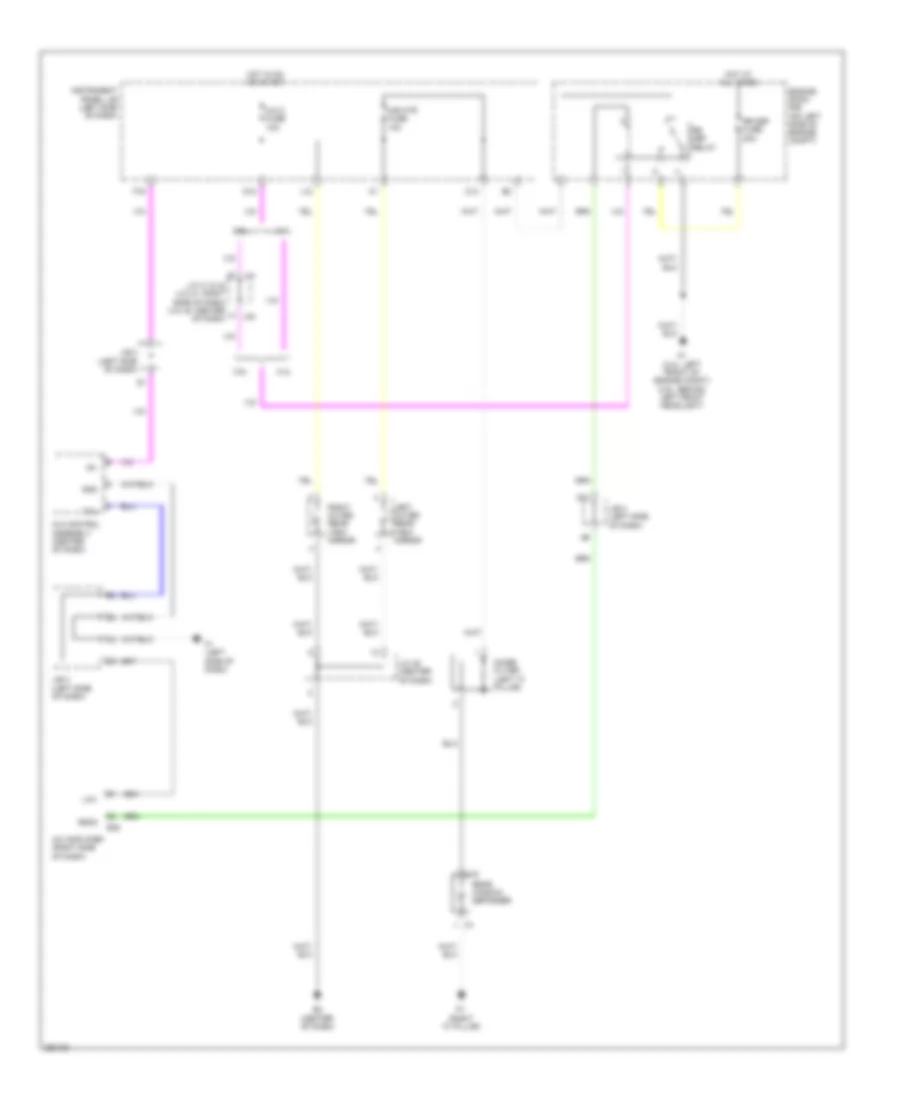
COOLING FAN
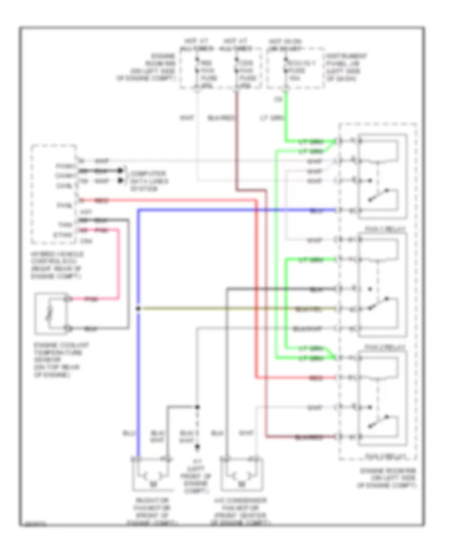
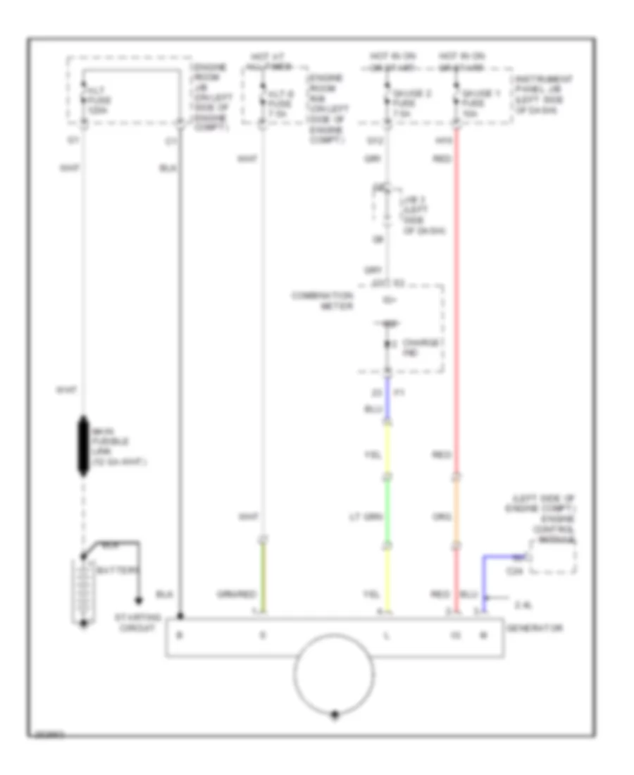
Cooling Fan Wiring Diagram, Hybrid for Toyota Camry CE 2007
List of elements for Cooling Fan Wiring Diagram, Hybrid for Toyota Camry CE 2007:
- A/c condenser fan motor (front center of engine compt)
- A1 (left front of engine compt)
- A61
- C64
- Canh
- Canl
- Cds fan fuse 40a
- Computer data lines system
- Ecu ig 1 fuse 10a
- Engine coolant temperature sensor (on top rear of engine)
- Engine room r/b (on left side of engine compt)
- Ethw
- Fan 1 relay
- Fan 2 relay
- Fan 3 relay
- Fanh
- Fanl
- Hot at all times
- Hot in on or start
- Hybrid vehicle control ecu (right rear of engine compt)
- Instrument panel j/b (left side of dash)
- Pnk
- Radiator fan motor (front of engine compt)
- Rdi fan fuse 40a
- Red
- Thw
2.4L
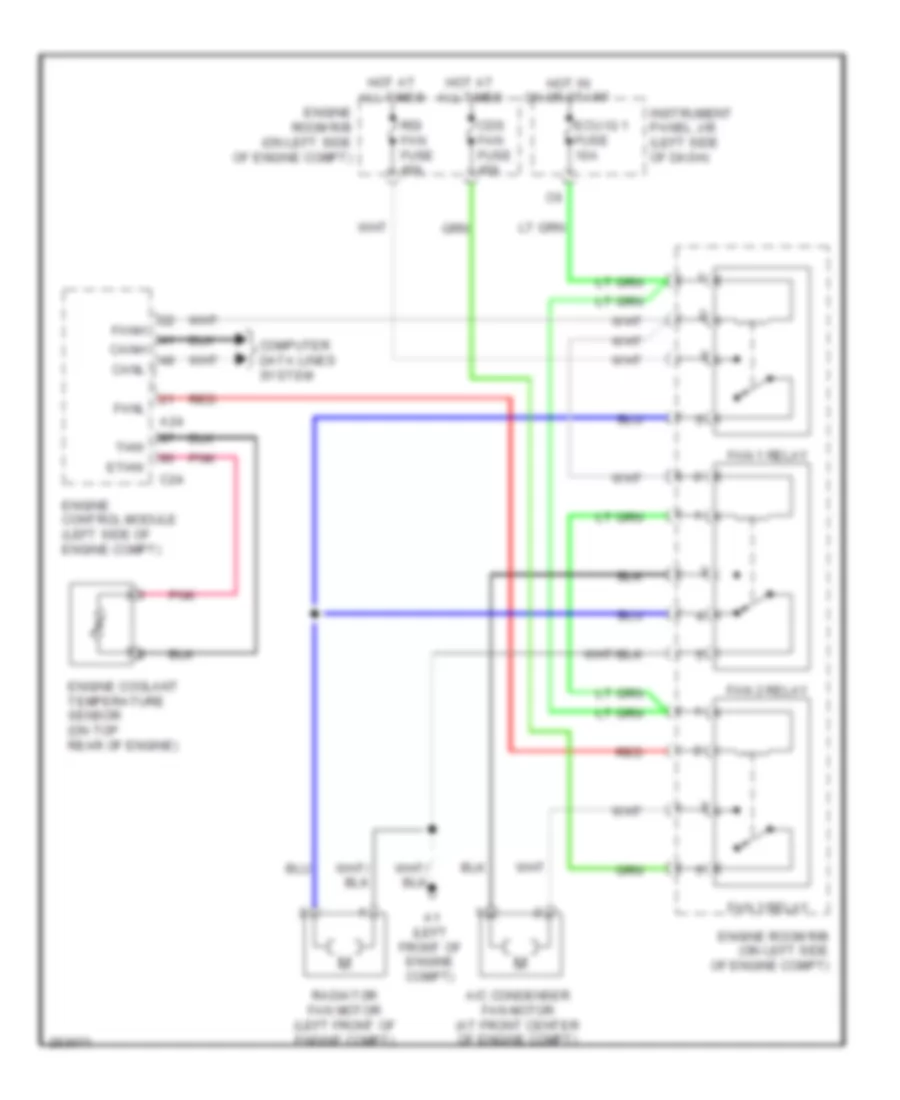
2.4L, Cooling Fan Wiring Diagram, Except Hybrid for Toyota Camry CE 2007
List of elements for 2.4L, Cooling Fan Wiring Diagram, Except Hybrid for Toyota Camry CE 2007:
- A/c condenser fan motor (at front center of engine compt)
- A1 (left front of engine compt)
- A24
- C24
- Canh
- Canl
- Cds fan fuse 40a
- Computer data lines system
- Ecu ig 1 fuse 10a
- Engine control module (left side of engine compt)
- Engine coolant temperature sensor (on top rear of engine)
- Engine room r/b (on left side of engine compt)
- Ethw
- Fan 1 relay
- Fan 2 relay
- Fan 3 relay
- Fanh
- Fanl
- Hot at all times
- Hot in on or start
- Instrument panel j/b (left side of dash)
- Pnk
- Radiator fan motor (left front of engine compt)
- Rdi fan fuse 40a
- Red
- Thw
3.5L
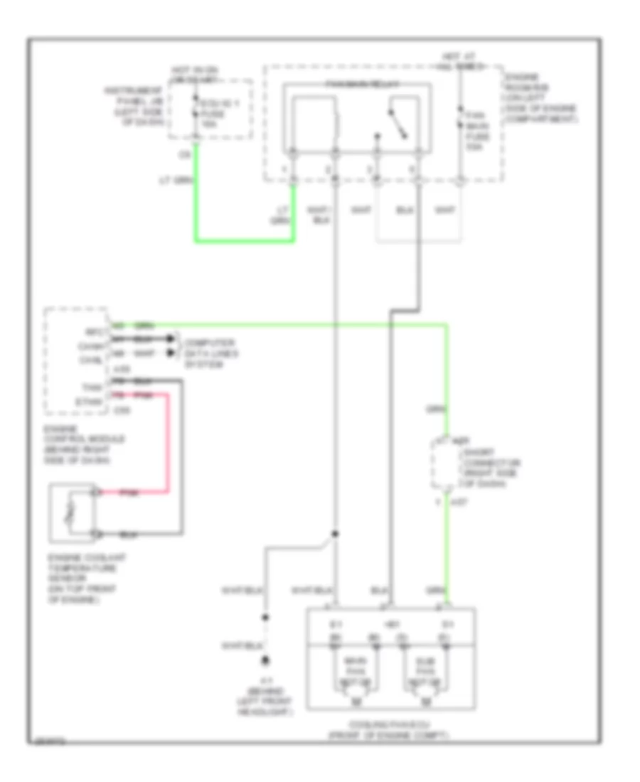
3.5L, Cooling Fan Wiring Diagram, Except Hybrid for Toyota Camry CE 2007
List of elements for 3.5L, Cooling Fan Wiring Diagram, Except Hybrid for Toyota Camry CE 2007:
- (m) m+
- (m) m-
- (s) m+
- (s) m-
- +b1
- A1 (behind left front headlight)
- A55
- A56
- A57
- C55
- Canh
- Canl
- Computer data lines system
- Cooling fan ecu (front of engine compt)
- Ecu ig 1 fuse 10a
- Engine control module (behind right side of dash)
- Engine coolant temperature sensor (on top front of engine)
- Engine room r/b (on left side of engine compartment)
- Ethw
- Fan main fuse 50a
- Fan main relay
- Hot at all times
- Hot in on or start
- Instrument panel j/b (left side of dash)
- Main fan motor
- Pnk
- Rfc
- Short connector (right side of dash)
- Sub fan motor
- Thw
CRUISE CONTROL
Cruise Control Wiring Diagram, Hybrid for Toyota Camry CE 2007
List of elements for Cruise Control Wiring Diagram, Hybrid for Toyota Camry CE 2007:
- (left side of dash) j/b 3
- (on transaxle) park/neutral position switch
- (right front of engine compt) skid control ecu
- (top rear of engine) c6
- +bm
- +bs
- +res
- -set
- A11
- A41
- A42
- A61
- A74
- Accelerator position sensor (on accelerator pedal assembly)
- B10
- C6 (top rear of engine)
- C64
- Can i/f
- Cancel
- Ccs
- Combination meter
- Computer data lines system
- Cruise control switch
- Cruise ind
- D10
- Drive ic
- E12
- E18
- E40
- Engine room r/b (on left side of engine compt)
- Ep1
- Ep2
- Eta
- Etcs fuse 10a
- F12
- G12
- Gauge fuse 7.5a
- Ge01
- Hot at all times
- Hot in on or start
- Hybrid vehicle control ecu (right rear of engine compt)
- Ig2
- Ign fuse 10a
- Igsw
- Instrument panel j/b (left side of dash)
- J/b 3 (left side of dash)
- J/c a41 & a42 (left side of dash)
- J/c a58 & e40 (left side of dash) a58
- K12
- Micro computer
- Nca
- On-off
- P11
- Pnk
- Red
- Spdi
- Spiral cable (left side of dash)
- St1-
- Stop fuse 10a
- Stop lamp switch (at brake pedal assembly)
- Stp
- Throttle body assembly (rear of intake manifold)
- Vcp1
- Vcp2
- Vcta
- Vpa
- Vpa1
- Vpa2
- Vta
- Vta2
2.4L
2.4L, Cruise Control Wiring Diagram, Except Hybrid for Toyota Camry CE 2007
List of elements for 2.4L, Cruise Control Wiring Diagram, Except Hybrid for Toyota Camry CE 2007:
- (j/c 42: center of dash)
- (left side of dash) j/b 3
- (on transaxle) park/neutral position switch
- (top rear of engine) c6
- +b2
- +bm
- +res
- -set
- A/t
- A11
- A24
- A3 (left side of dash)
- A41
- A42
- A58
- Accelerator position sensor (on accelerator pedal assembly)
- B10
- C24
- C4 (top rear of engine)
- C6 (top rear of engine)
- Can i/f
- Cancel
- Canh
- Canl
- Ccs
- Combination meter
- Computer data lines system
- Cruise control clutch switch (behind left side of dash)
- Cruise control switch
- Cruise ind
- D10
- Drive ic
- E02
- E10
- E11
- E12
- E18
- E40
- Ecu ig 2 fuse 7.5a
- Efi 2 fuse 15a
- Efi main fuse 30a
- Efi relay
- Engine control module (left side of engine compt)
- Engine room j/b (on left side of engine compt)
- Engine room r/b (on left side of engine compt)
- Epa
- Epa2
- Eta
- Etcs fuse 10a
- F12
- F19
- G12
- Gauge fuse 10a
- Gauge fuse 7.5a
- Ge01
- H16
- Hot at all times
- Hot in on or start
- Ig2
- Ign fuse 10a
- Igsw
- Instrument panel j/b (left side of dash)
- J/b 3 (left side of dash)
- J/c 41 & 42 (j/c 41: right side of dash)
- J/c 41 & 42 (j/c 41: right side of dash) (j/c 42: center of dash)
- J/c 58 & 40 (j/c 58: left side of dash) (j/c 40: right side of dash)
- K12
- M/t
- Micro computer
- Mrel
- Nca
- On-off
- Pnk
- Red
- Spd
- Spiral cable (center of dash)
- St1-
- Stop fuse 10a
- Stop lamp switch
- Stp
- Throttle body assembly (rear of intake manifold)
- Transmissions system
- Vcp2
- Vcpa
- Vcta
- Vpa
- Vpa2
- Vta
- Vta1
- Vta2
3.5L
3.5L, Cruise Control Wiring Diagram, Except Hybrid for Toyota Camry CE 2007
List of elements for 3.5L, Cruise Control Wiring Diagram, Except Hybrid for Toyota Camry CE 2007:
- (left side of dash) j/b 3
- (on transaxle) park/neutral position switch
- (right side of dash) j/c 41
- +b2
- +bm
- +res
- -set
- A11
- A3 (left side of dash)
- A41
- A42
- A55
- Accelerator position sensor (on accelerator pedal assembly)
- B10
- C4 (top of engine)
- C55
- C55 c55
- Can i/f
- Can+
- Can-
- Cancel
- Canh
- Canl
- Ccs
- Combination meter
- Computer data lines system
- Cruise control switch
- Cruise ind
- D10
- Drive ic
- E04
- E10
- E11
- E12
- E18
- E40
- Efi 2 fuse 15a
- Efi main fuse 30a
- Efi relay
- Engine control module (behind right side of dash)
- Engine room j/b (on left side of engine compt)
- Engine room r/b (on left side of engine compt)
- Epa
- Epa2
- Eta
- Etcs fuse 10a
- F12
- G12
- Gauge 1 fuse 10a
- Gauge fuse 7.5a
- Ge01
- H16
- Hot at all times
- Hot in on or start
- Ig2
- Ign fuse 10a
- Igsw
- Instrument panel j/b (left side of dash)
- J/b 3 (left side of dash)
- J/c 41 & 42 (j/c 41: right side of dash) (j/c 42: center of dash)
- J/c 57 (rear of engine compt)
- J/c 58 & 40 (j/c 58: left side of dash) (j/c 40: right a58
- K12
- Micro computer
- Mrel
- Nca
- On-off
- Pnk
- Red
- Side of dash)
- Spd
- Spiral cable (center of dash)
- St1-
- Stop fuse 10a
- Stop lamp switch
- Stp
- Throttle body assembly (top rear of engine)
- Transmissions system
- Vcp2
- Vcpa
- Vcta
- Vpa
- Vpa2
- Vta
- Vta1
- Vta2
DEFOGGERS
Defoggers Wiring Diagram, Except Hybrid for Toyota Camry CE 2007
List of elements for Defoggers Wiring Diagram, Except Hybrid for Toyota Camry CE 2007:
- 2.4l
- 3.5l
- A/c 2 fuse 10a
- A/c amplifier (right side of dash)
- A/c control assembly (center of dash)
- A1 (2.4l: left front of engine compt) (3.5l: behind left front headlight)
- D12
- E2 (center of dash)
- E38
- Engine room r/b (on left side of engine compt)
- F1 (left side of dash)
- F16
- Gnd
- Hot at all times
- Hot in on or start
- Ig+
- Instrument panel j/b (left side of dash)
- J/b 3 (left side of dash)
- J/c 41 & 42 (j/c 41: right side of dash) (j/c 42: center of dash)
- J/c 49 (center of dash)
- J12
- J41
- J42
- Left outer rear view mirror
- Lin1
- Mir htr fuse 10a
- N19
- Noise filter (left "c" pillar)
- O13
- P1 (right "c" pillar)
- Rdfg
- Rear window defogger
- Right outer rear view mirror
- Rr def fuse 50a
- Rr def relay
- Tx+
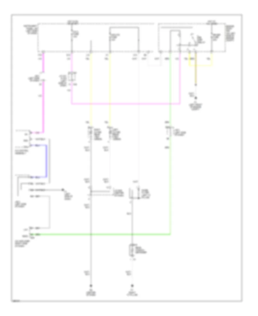
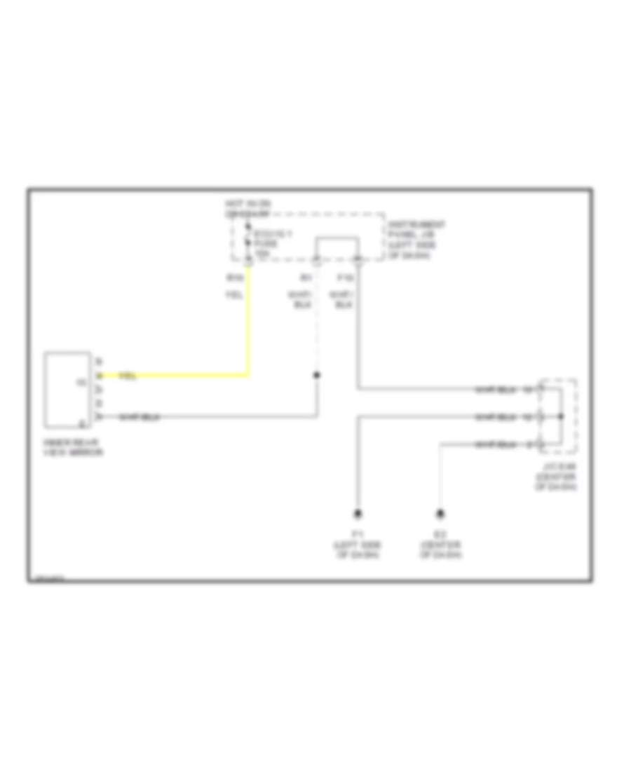
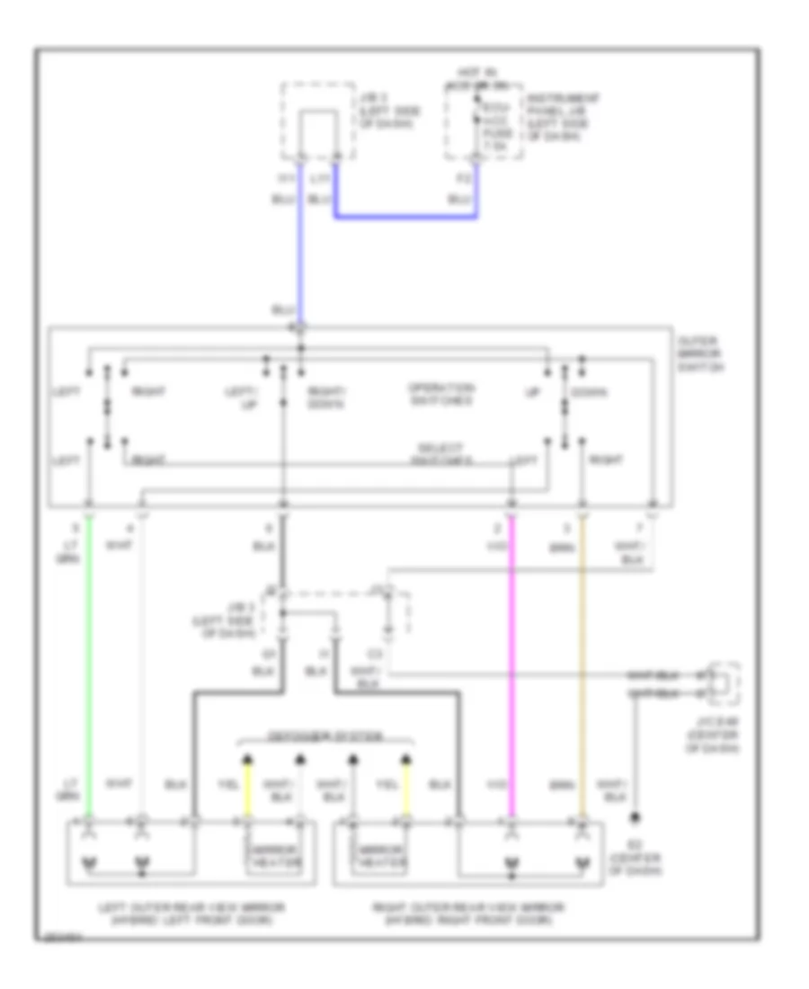
Defoggers Wiring Diagram, Hybrid for Toyota Camry CE 2007
List of elements for Defoggers Wiring Diagram, Hybrid for Toyota Camry CE 2007:
- A/c 2 fuse 10a
- A/c amplifier (right side of dash)
- A/c control assembly
- A1 (left front of engine compt)
- A41
- A42
- D12
- E2 (center of dash)
- E38
- Engine room r/b (on left side of engine compt)
- F1 (left side of dash)
- F16
- Gnd
- Hot at all times
- Hot in on or start
- Ig+
- Instrument panel j/b (left side of dash)
- J/b 3 (left side of dash)
- J/c a41 & a42 (left side of dash)
- J/c e49 (center of dash)
- J12
- Left outer rear view mirror
- Lin1
- Mir htr fuse 10a
- N19
- Noise filter (left "c" pillar)
- O13
- P1 (right "c" pillar)
- Rdfg
- Rear window defogger
- Right outer rear view mirror
- Rr def fuse 50a
- Rr def relay
- Tx+
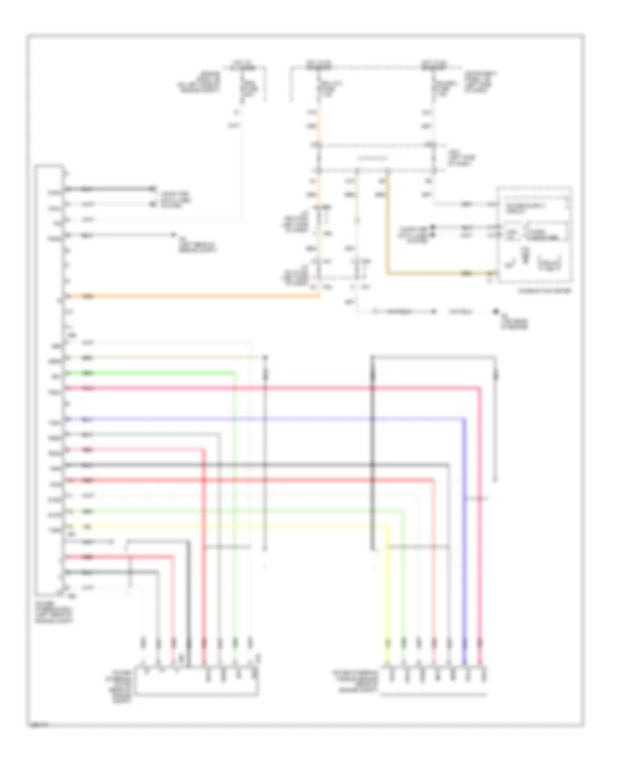
ELECTRONIC POWER STEERING
Electronic Power Steering Wiring Diagram, Hybrid for Toyota Camry CE 2007
List of elements for Electronic Power Steering Wiring Diagram, Hybrid for Toyota Camry CE 2007:
- A41
- A42
- A58
- A66
- A67
- A68
- A69
- A70
- A9 (left rear of engine compt)
- C6 (top rear of engine)
- Can i/f
- Canh
- Canl
- Combination meter
- Computer data lines system
- D10
- Drive ic
- E40
- Ecu ig 2 fuse 7.5a
- Engine room j/b (on left side of engine compt)
- Eps fuse 80a
- F19
- G12
- Gauge 2 fuse 7.5a
- Hot at all times
- Hot in on or start
- Ig2
- Incs
- Insn
- Instrument panel j/b (left side of dash)
- J/b 3 (left side of dash)
- J/c a41 & a42 (left side of dash)
- J/c a58 & e40 (left side of dash)
- Micro computer
- Nca
- Oucs
- Ousn
- P/s ind
- Pgnd
- Pig
- Pnk
- Power steering ecu (left rear of engine compt)
- Power steering motor (rear of engine compt)
- Power steering torque sensor (rear of engine compt)
- Red
- Rzcs
- Rzg
- Rzsn
- Rzv
- Srzg
- Tqg1
- Tqg2
- Trqv
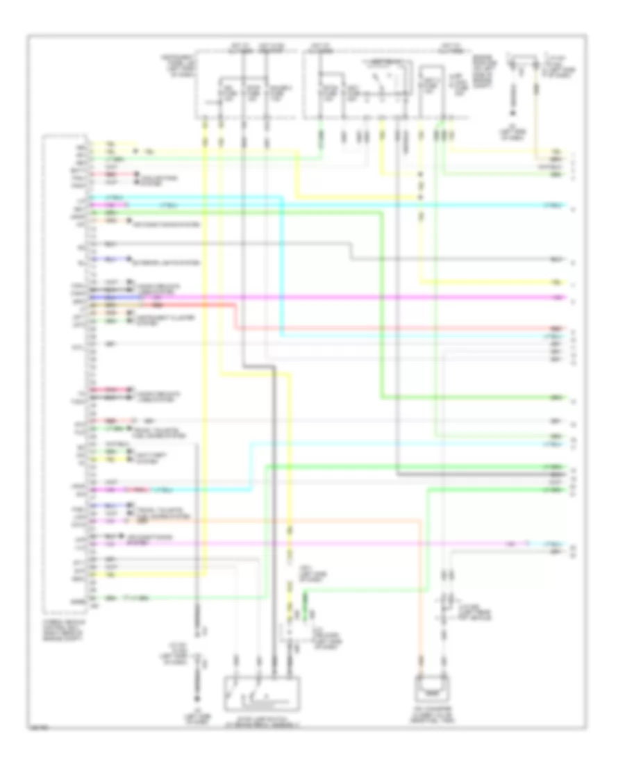
ENGINE PERFORMANCE
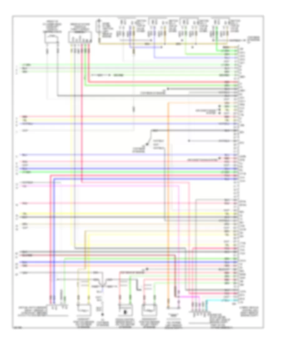
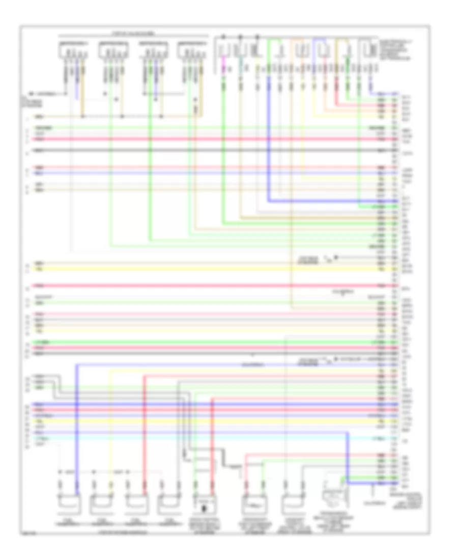
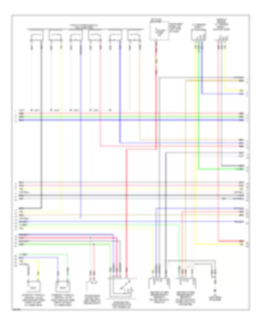
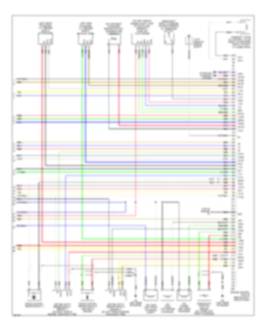
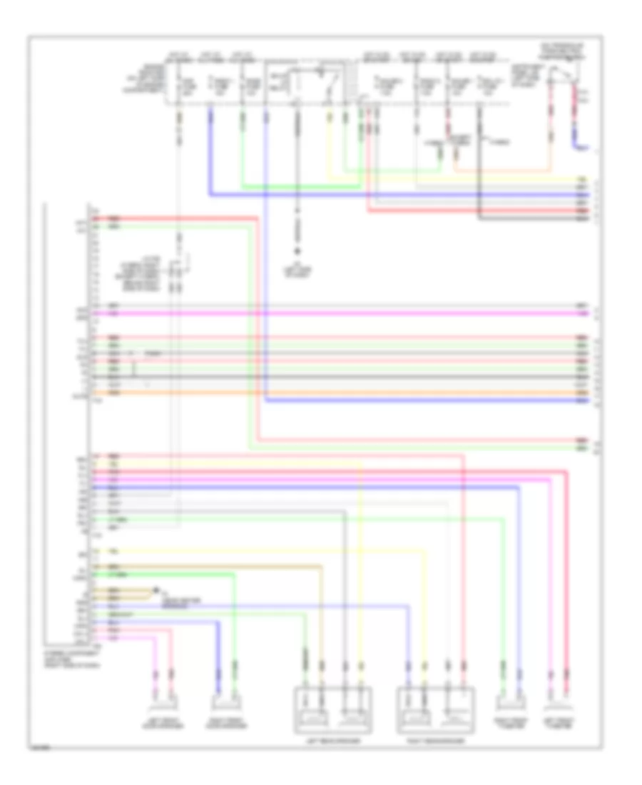
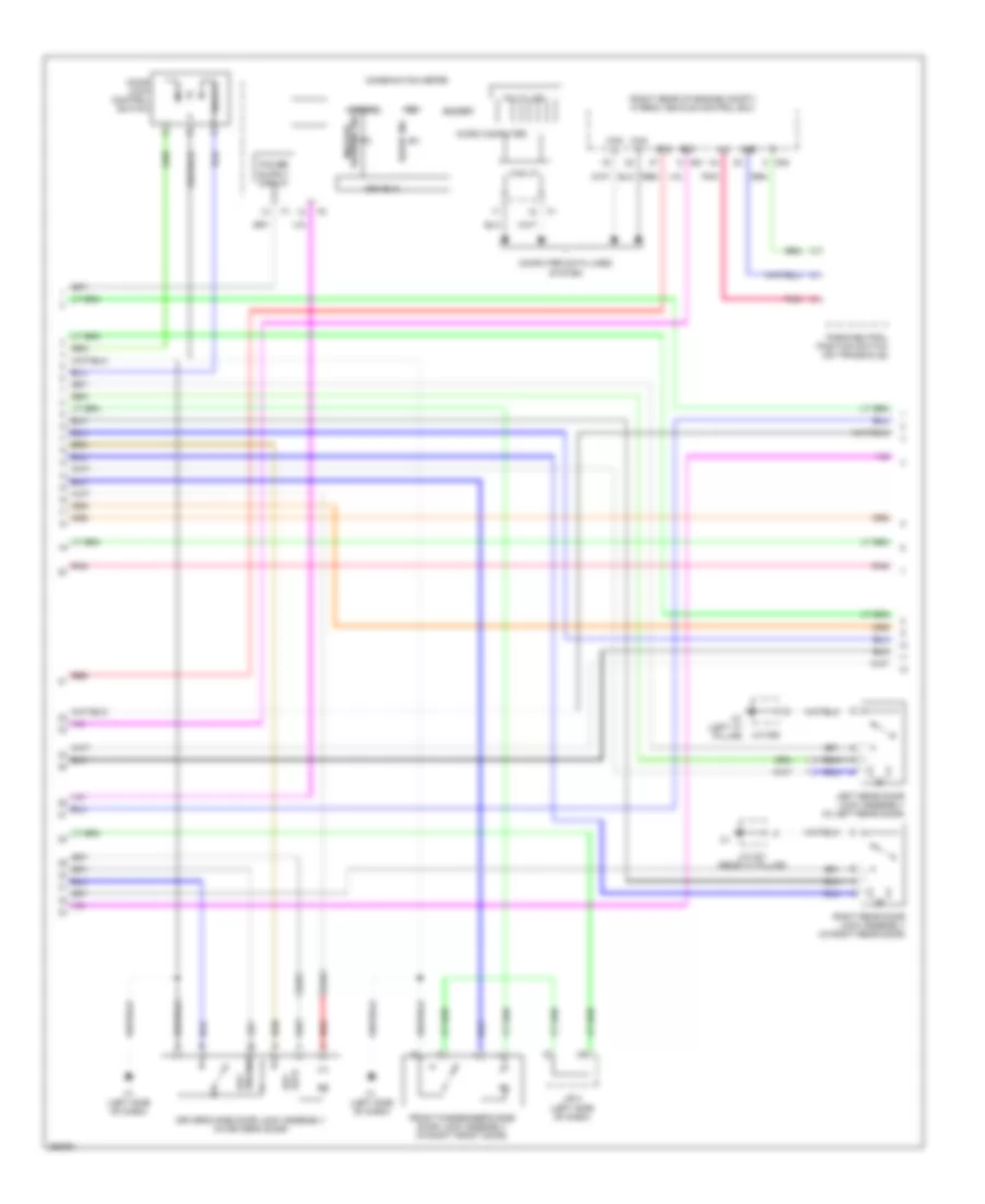
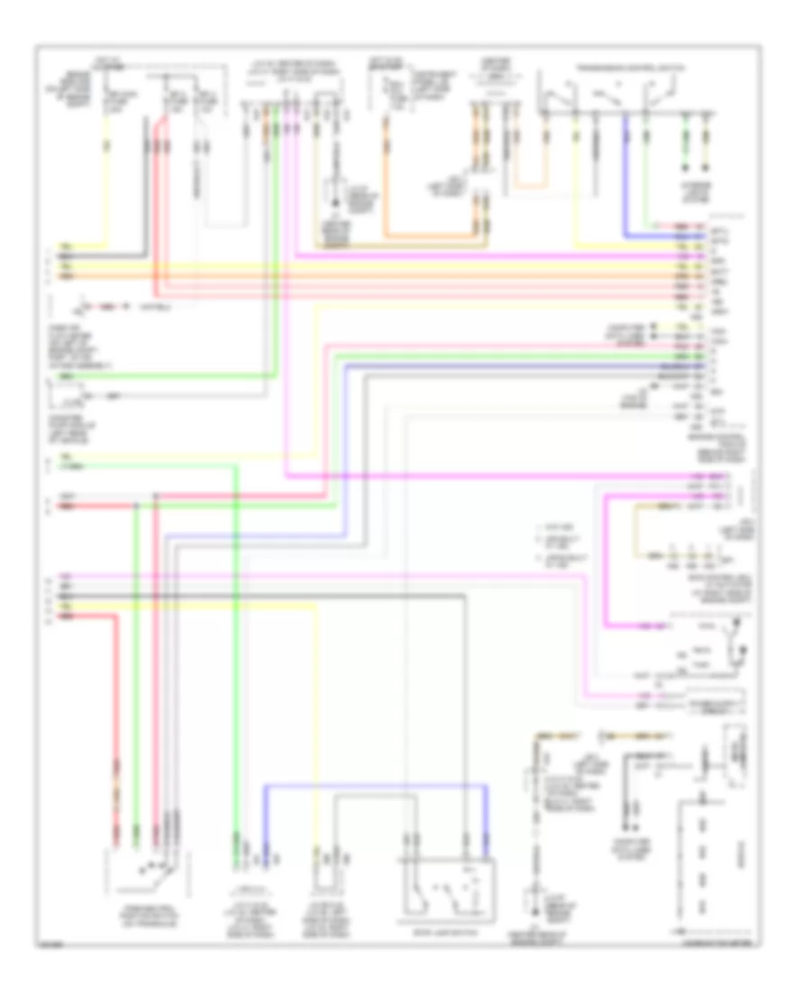
Hybrid System Wiring Diagram (1 of 7) for Toyota Camry CE 2007
List of elements for Hybrid System Wiring Diagram (1 of 7) for Toyota Camry CE 2007:
- +b1
- +b2
- +bm
- A3 (left side of dash)
- A41
- A42
- A58
- A61
- Air conditioning system
- Anti-theft system
- Batt
- Canh
- Canl
- Ccv2
- Computer data lines system
- Cooling fans system
- E40
- Efi main fuse 30a
- Engine room r/b (on left side of engine compt)
- Etcs fuse 10a
- Exterior lights system
- F12
- Fanh
- Fanl
- Fctl
- Fuel
- Fuo
- G12
- Gauge 2 fuse 7.5a
- Hot at all times
- Hot in on or start
- Hybrid vehicle control ecu (right rear of engine compt)
- Igct 2 fuse 10a
- Igct fuse 30a
- Igct relay
- Ign fuse 10a
- Igsw
- Ilk
- Imi
- Imo
- Instrument cluster system
- Instrument panel j/b (left side of dash)
- Iwp
- J/b 3 (left side of dash)
- J/c a41 & a42 (left side of dash)
- J/c a58 & e40 (left side of dash)
- J/c n28 (left rear of vehicle)
- K12
- Lido
- Lst1
- Lst2
- Mpmp
- Pnk
- Rdy
- Red
- Sio
- Smrb
- Spdi
- St1-
- St2
- Stop fuse 10a
- Stop lamp switch (at brake pedal assembly)
- Stp
- Tach
- Trunk, tailgate, fuel doors system
- Vlo
- Vpmp
- Vsv (canister closed valve) (near fuel tank)
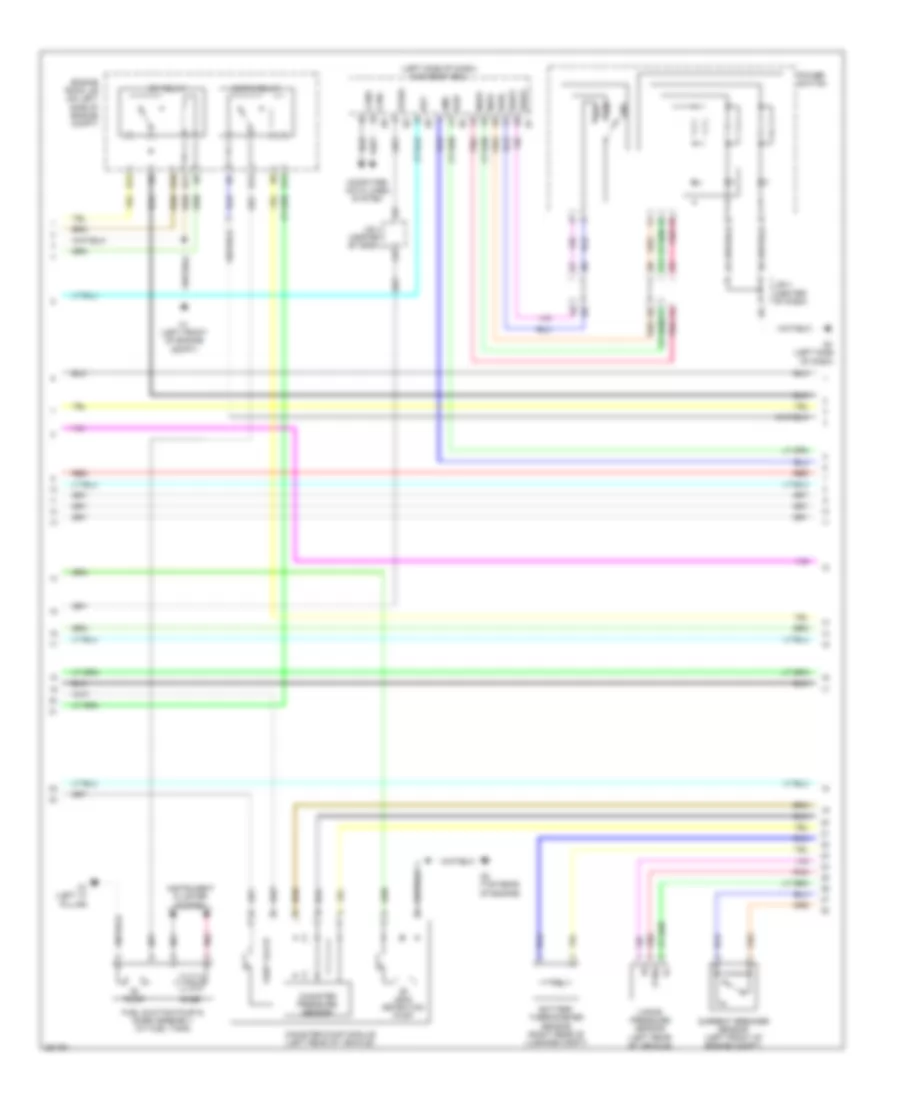
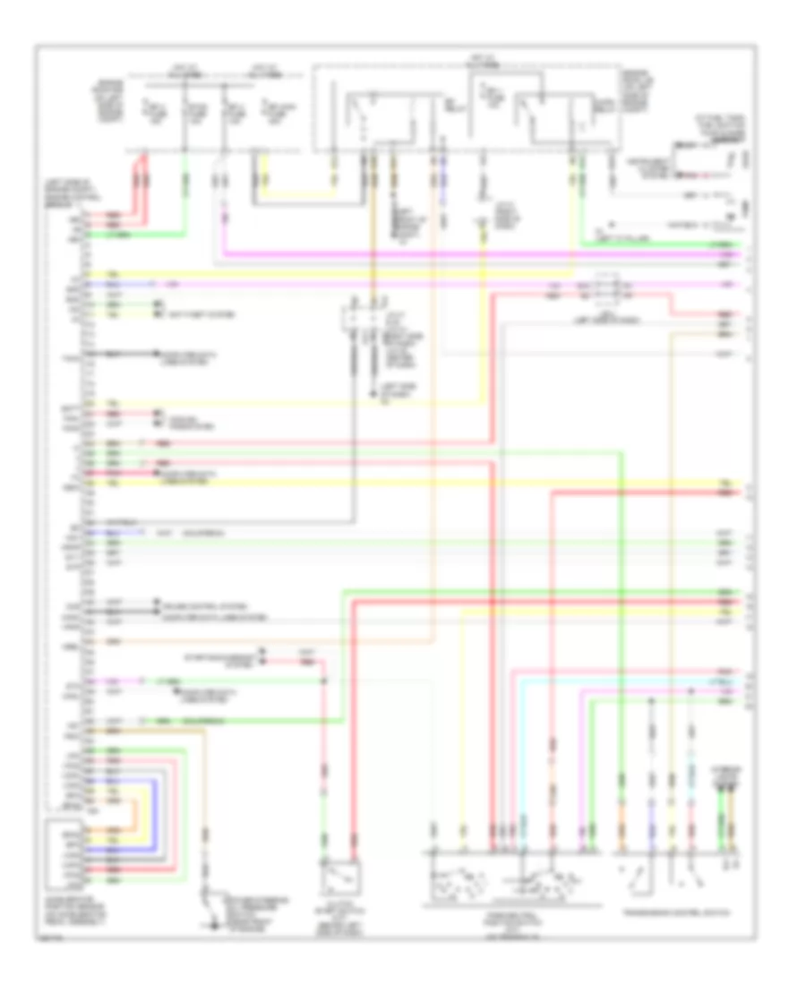
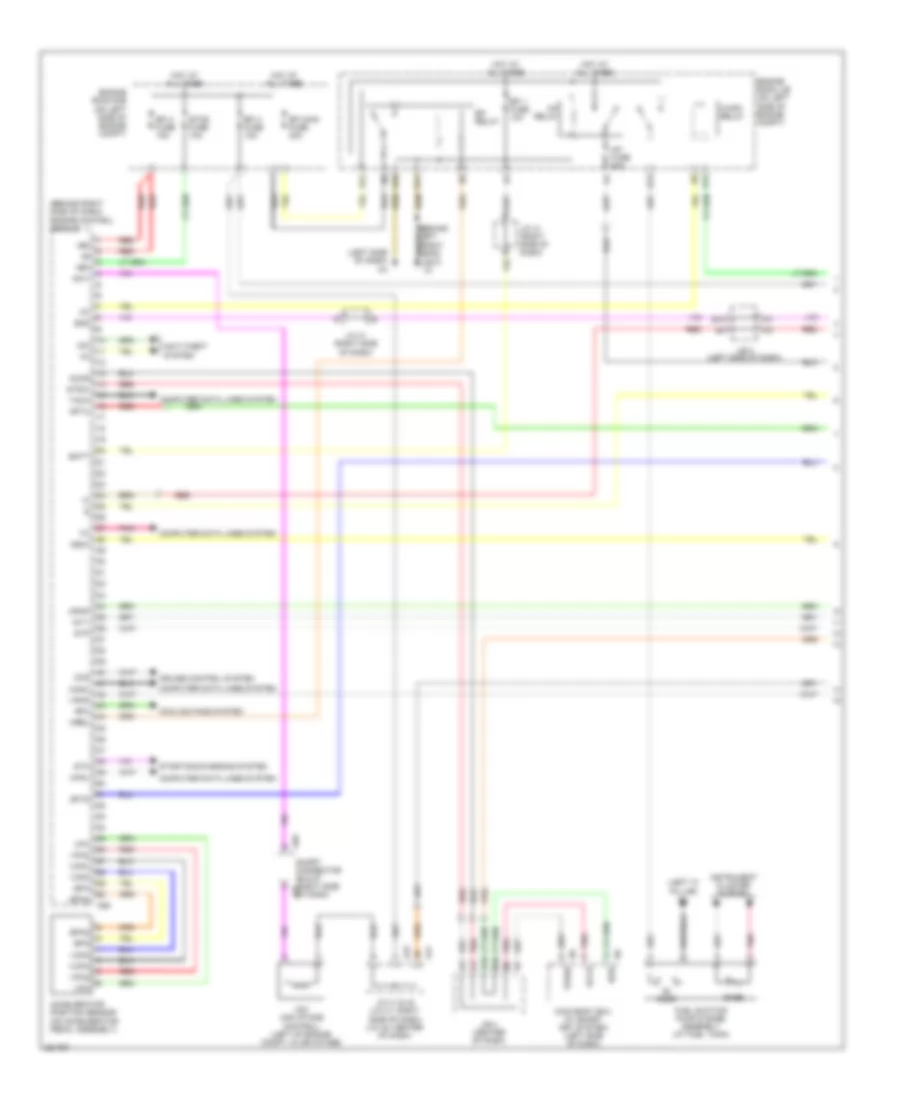
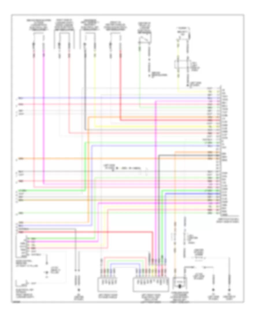
Hybrid System Wiring Diagram (2 of 7) for Toyota Camry CE 2007
List of elements for Hybrid System Wiring Diagram (2 of 7) for Toyota Camry CE 2007:
- (left side of dash) main body ecu
- A1 (left front of engine compt)
- Am2
- Battery thermometer sensor (right rear of luggage compt)
- C/opn relay
- C6 (top rear of engine)
- Canh
- Canister pressure sensor
- Canister pump module (left rear of vehicle)
- Canl
- Computer data lines system
- Current breaker sensor (left front of engine compt)
- D12
- E1 (left side of dash)
- E10
- E11
- E12
- E13
- Efi relay
- Engine room j/b (on left side of engine compt)
- Fuel suction pump & gage assembly (at fuel tank)
- G11
- Gage
- Gnd
- Ig2d
- Inds
- Indw
- Instrument cluster system
- J/b 4 (center of dash)
- Leak detection pump
- N1 (left "c" pillar)
- Pnk
- Power switch
- Ptnk
- Pump
- Rdy
- Red
- Ss1
- Ss2
- Ssw1
- Ssw2
- Stsw
- Swil
- Vapor pressure sensor (left rear of vehicle)
- Vent valve
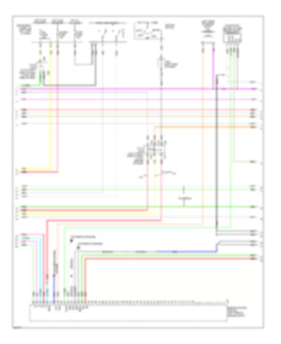
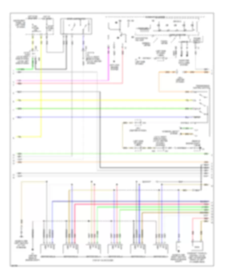
Hybrid System Wiring Diagram (3 of 7) for Toyota Camry CE 2007
List of elements for Hybrid System Wiring Diagram (3 of 7) for Toyota Camry CE 2007:
- (left side of engine compt) inverter
- +b2
- A61
- A62
- Abfs
- As1
- As1g
- Bth+
- Bth-
- Ccs
- Clk+
- Clk-
- Cruise control system
- Drn1
- Drn2
- Drn3
- Drn4
- Drn5
- Drn8
- Eib
- Ep1
- Ep2
- Eppm
- Eptk
- Gmt
- Gmtg
- Gnd
- Gnd1
- Gnd2
- Hsdn
- Htm+
- Htm-
- Hybrid vehicle control ecu (right rear of engine compt)
- Ilk
- Ilki
- Ilko
- Inter lock switch (in hybrid vehicle battery)
- J/c a43 (left front of engine compt)
- J/c n6 (in hybrid vehicle battery)
- J/c o21 (rear "c" pillar)
- Mmt
- Mmtg
- Mrel
- Mth+
- Mth-
- Nodd
- O1 (right "c" pillar)
- Pnk
- Ppmp
- Ptnk
- Red
- Req+
- Req-
- Smrg
- Smrp
- Thb
- Vcp1
- Vcp2
- Vcpp
- Vcpt
- Vpa
- Vpa2
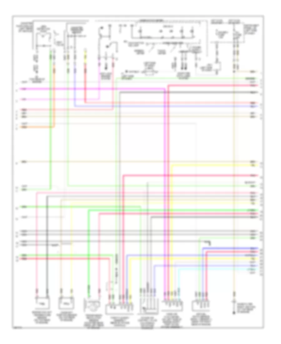
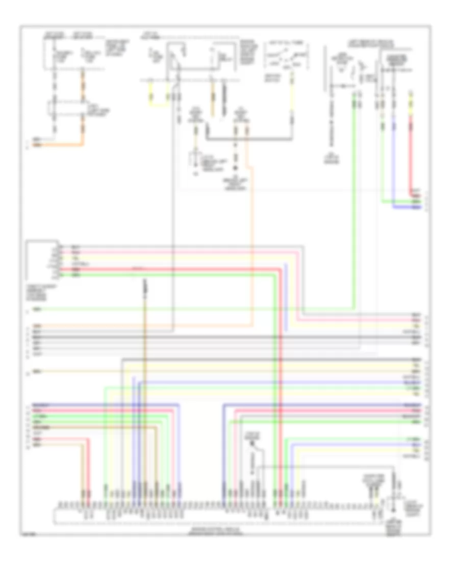
Hybrid System Wiring Diagram (4 of 7) for Toyota Camry CE 2007
List of elements for Hybrid System Wiring Diagram (4 of 7) for Toyota Camry CE 2007:
- (left front of engine compt) motor generator 1
- (left side of engine compt) inverter
- (top rear of engine) c6
- A41
- A42
- Accelerator position sensor (on accelerator pedal assembly)
- Acpb
- Acpe
- Air conditioning system
- Amd
- C58
- C59
- C60
- C61
- Cbi
- Cei
- Converter (in hybrid vehicle battery)
- Dc/dc fuse 120a
- Drn6
- Engine room j/b (on left side of engine compt)
- Ep1
- Ep2
- Gcs
- Gcsg
- Gmt
- Gmtg
- Gnd
- Grf
- Grfg
- Gsn
- Gsng
- Hot at all times
- Idh
- Igct
- In+
- In-
- J/c a41 & a42 (left side of dash)
- J/c n6 (in hybrid vehicle battery)
- Mcs
- Mcsg
- Mmt
- Mmtg
- Motor generator 2 (left side of engine compt)
- Mrf
- Mrfg
- Msn
- Msng
- Nca
- Nodd
- Pnk
- Prec
- Red
- Smrp
- Vcp1
- Vcp2
- Vlo
- Vpa1
- Vpa2
Hybrid System Wiring Diagram (5 of 7) for Toyota Camry CE 2007
List of elements for Hybrid System Wiring Diagram (5 of 7) for Toyota Camry CE 2007:
- Batt fan fuse 10a
- Batt fan relay
- Battery blower motor (rear of vehicle)
- Battery voltage sensor
- Bth+
- Bth-
- Busbar module 1
- Busbar module 2
- Current sensor
- Engine room r/b (on left side of engine compt)
- Fuse 15a
- Gb0
- Gb0 r3
- Gb1
- Gb2
- Gb3
- Gc0
- Gib
- Gnd
- Gnd0
- Hot at all times
- Hybrid vehicle battery
- Hybrid vehicle battery (in rear of vehicle)
- Ib o1
- Idh
- Ig0
- Igc1
- J/c n29
- J/c n6 (in hybrid vehicle battery)
- J/c o21 (rear "c" pillar)
- Main relay
- N1 (left "c" pillar)
- Nca
- Pnk
- Red
- Service plug
- Si0
- System main relay (in hybrid vehicle battery)
- Tb0
- Tb1
- Tb2
- Tb3
- Tc0
- Vb1
- Vb10
- Vb11
- Vb12
- Vb13
- Vb14
- Vb15
- Vb16
- Vb17
- Vb2
- Vb3
- Vb4
- Vb5
- Vb6
- Vb7
- Vb8
- Vb9
- Vib
- Vm0
Hybrid System Wiring Diagram (6 of 7) for Toyota Camry CE 2007
List of elements for Hybrid System Wiring Diagram (6 of 7) for Toyota Camry CE 2007:
- (on transaxle) park/neutral position switch
- (top rear of engine) c6
- A1 (left front of engine compt)
- A41
- A42
- Am2 fuse 7.5a
- Anti-lock brakes system
- B10
- Buzzer
- Can i/f
- Combination meter
- Computer data lines system
- D10
- Drive ic
- E10
- E12
- Efi 3 fuse 10a
- Engine coolant temperature sensor (on top rear of engine)
- Engine oil pressure switch (rear of engine)
- Engine room r/b (on left side of engine compt)
- Fuel expenses gauge
- Fuel injectors (top of intake manifold)
- Heated oxygen sensor (bank 1 sensor 2) (in exhaust)
- Hot at all times
- Ig2
- Ig2 fuse 20a
- Ig2 relay
- J/b 3 (left side of dash)
- J/b 4 (center of dash)
- J/b a41 & a42 (left side of dash)
- M10
- M12
- Malfunction ind lamp
- Micro computer
- Multi lcd
- Nca
- Pnk
- Red
- Temperature gauge
Hybrid System Wiring Diagram (7 of 7) for Toyota Camry CE 2007
List of elements for Hybrid System Wiring Diagram (7 of 7) for Toyota Camry CE 2007:
- (front of cylinder head) camshaft timing oil control valve
- (rear of intake manifold) throttle body assembly
- (top rear of engine) c4
- +bs
- A1a+
- A1a-
- Af+
- Af-
- Air conditioning system
- Air fuel ratio sensor (bank 1 sensor 1) (in exhaust, before catalytic converter)
- C4 (top rear of engine)
- C6 (top rear of engine)
- C64
- Camshaft position sensor (on top rear of engine)
- Clk
- Crankshaft position sensor (on left front of engine)
- E01
- E02
- E03
- E04
- E12
- E2g
- Eknk
- Eta
- Etha
- Ethw
- Eti
- Evg
- G2+
- G2-
- Ge01
- Gnd
- Ha1a
- Ht1b
- Hybrid vehicle control ecu (right rear of engine compt)
- Igf
- Ignition coil 1 (top of valve cover)
- Ignition coil 2 (top of valve cover)
- Ignition coil 3 (top of valve cover)
- Ignition coil 4 (top of valve cover)
- Igt1
- Igt2
- Igt3
- Igt4
- Ite
- Knk1
- Knock control sensor (bank 1) (on top center of engine)
- Mass air flow meter (on left side of engine compt, part of air intake assembly)
- Me01
- Mops
- Nca
- Ne+
- Ne-
- Noise filter (ignition) (left rear of engine)
- O1b-
- Oc1+
- Oc1-
- Ox1b
- Pnk
- Prg
- Red
- Stb
- Tha
- Thw
- Vcta
- Vsv (purge) (left rear of engine compt)
- Vta
- Vta2
2.4L
2.4L, Engine Controls Wiring Diagram (1 of 4) for Toyota Camry CE 2007
List of elements for 2.4L, Engine Controls Wiring Diagram (1 of 4) for Toyota Camry CE 2007:
- (at fuel tank) fuel suction pump & gage assembly
- (california)
- (left front of engine compt)
- (left side of dash) a3
- (left side of engine compt) engine control module
- +b2
- +bm
- A24
- A41
- A41 j/c 41 & 42 (j/c 41: right side a42
- Accelerator position sensor (on accelerator pedal assembly)
- Anti-theft system
- B10
- Batt
- C/opn relay
- Canh
- Canl
- Ccs
- Clutch start switch (m/t) (behind left side of dash)
- Computer data lines system
- Cooling fans system
- Cruise control system
- D12
- E10
- E11
- E12
- E13
- Efi 1 fuse 10a
- Efi 2 fuse 15a
- Efi 3 fuse 10a
- Efi main fuse 30a
- Efi relay
- Engine room j/b (on left side of engine compt)
- Engine room r/b (on left side of engine compt)
- Eom
- Epa
- Epa2
- Etcs fuse 10a
- Fanh
- Fanl
- Gage
- Hot at all times
- Iac+
- Iac-
- Igsw
- Ill+
- Ill-
- Imi
- Imo
- Instrument cluster system
- Interior lights system
- J/b 3 (left side of dash)
- J/c 41 (right side of dash)
- Mpmp
- Mrel
- N1 (left "c" pillar)
- Of dash) (j/c 42: center of dash)
- P r
- Park/neutral position switch (a/t) (0n transaxle)
- Pnk
- Power steering oil pressure switch (near front of engine)
- Psw
- Pump
- Red
- Spd
- St1-
- Sta
- Starting/charging system
- Stp
- Tach
- Transmission control switch
- Vcp2
- Vcpa
- Vpa
- Vpa2
- Vpmp
2.4L, Engine Controls Wiring Diagram (2 of 4) for Toyota Camry CE 2007
List of elements for 2.4L, Engine Controls Wiring Diagram (2 of 4) for Toyota Camry CE 2007:
- (in exhaust) heated oxygen sensor (bank 1 sensor 2)
- (left rear of engine compt) vsv (purge)
- (top rear of engine) c4
- (top rear of engine) c6
- A/t
- A41
- A42
- A58
- Acc
- Alt
- C24
- California
- E01
- E02
- E04
- E40
- Engine control module (left side of engine compt)
- Gauge 1 fuse 10a
- H16
- Hot at all times
- Hot in on or start
- Ht1b
- Ign fuse 10a
- Ignition switch
- Instrument panel j/b (left side of dash)
- J/b 3 (left side of dash)
- J/c 40 & 58 (j/c 40: right side of dash) (j/c 58: left side of dash)
- J/c 41 & 42 (j/c 41: right side of dash) (j/c 42: center of dash)
- Lock
- M/t
- Me01
- Nca
- Nsw
- Off
- Ox1b
- Pnk
- Prg
- Red
- Run
- Start
- Stop fuse 10a
- Stop lamp switch
- System starting/charging
2.4L, Engine Controls Wiring Diagram (3 of 4) for Toyota Camry CE 2007
List of elements for 2.4L, Engine Controls Wiring Diagram (3 of 4) for Toyota Camry CE 2007:
- (left side of dash) j/b 3
- (top rear of engine)
- 4, 3, 2 & l
- A1a+
- A1a-
- Air fuel ratio sensor (bank 1 sensor 1) (near top right rear of engine)
- Anti-lock brakes system
- Camshaft position sensor (on top rear of engine)
- Can i/f
- Canister pressure sensor
- Canister pump module (left rear of vehicle)
- Combination meter
- Computer data lines system
- Drive ic
- E2g
- Engine coolant temperature sensor (on top rear of engine)
- F1 (left side of dash)
- G12
- Gauge 2 fuse 7.5a
- Ha1a
- Hot in on or start
- Ig2
- Inj fuse 15a
- Instrument panel j/b (left side of dash)
- Intake air control valve (california) (on intake manifold)
- J/b 3 (left side of dash)
- Leak detection pump
- Malfunction ind lamp
- Mass air flow meter (on left side of engine compt, part of air intake assembly)
- Micro computer
- Nca
- Noise filter (right ignition) (at top rear of engine)
- Pnk
- Red
- Speedo- meter
- Tacho- meter
- Tha
- Throttle body assembly (rear of intake manifold)
- Transmission revolution sensor (counter gear) (near left rear of engine)
- Vent valve
- Vta
- Vta2
2.4L, Engine Controls Wiring Diagram (4 of 4) for Toyota Camry CE 2007
List of elements for 2.4L, Engine Controls Wiring Diagram (4 of 4) for Toyota Camry CE 2007:
- (top of intake manifold)
- (top of valve cover)
- (top rear of engine)
- A1a+
- A1a-
- C24
- C4 (top rear of engine)
- California
- Camshaft timing oil control valve (front of engine)
- Crankshaft position sensor (on left front of engine)
- Dsl
- E03
- E2g
- Eia
- Eknk
- Electronically controlled transmission solenoid (on transaxle)
- Engine control module (left side of engine compt)
- Eppm
- Eta
- Etha
- Etho
- Ethw
- Ex1b
- Fuel injector 1
- Fuel injector 2
- Fuel injector 3
- Fuel injector 4
- G2+
- G2-
- Ge01
- Gnd
- Ha1a
- Iaca
- Igf
- Igf1
- Ignition coil 1
- Ignition coil 2
- Ignition coil 3
- Ignition coil 4
- Igt1
- Igt2
- Igt3
- Igt4
- Knk1
- Knock control sensor (bank 1) (on top center of engine)
- Nc+
- Nc-
- Nca
- Ne+
- Ne-
- Nt+
- Nt-
- Oc1+
- Oc1-
- Ox1b
- Pnk
- Ppmp
- Red
- Sl1+
- Sl1-
- Sl2+
- Sl2-
- Sl3+
- Sl3-
- Slt+
- Slt-
- Tha
- Tho
- Tho1
- Thw
- Transmission revolution sensor (turbine) (near left rear of engine)
- Vcia
- Vcpp
- Vcta
- Vta1
- Vta2
3.5L
3.5L, Engine Controls Wiring Diagram (1 of 5) for Toyota Camry CE 2007
List of elements for 3.5L, Engine Controls Wiring Diagram (1 of 5) for Toyota Camry CE 2007:
- (behind right side of dash) engine control module
- (left "c" pillar) n1
- (left side of dash) a3
- +b2
- +bm
- A/f fuse 20a
- A/f relay
- A41
- A42
- A55
- A56
- Accelerator position sensor (on accelerator pedal assembly)
- Accr
- Aciv
- Anti-theft system
- B10
- Batt
- C/opn relay
- Canh
- Canl
- Ccs
- Computer data lines system
- Cooling fans system
- Cruise control system
- D12
- E10
- E11
- E12
- E13
- Efi 1 fuse 10a
- Efi 2 fuse 15a
- Efi 3 fuse 10a
- Efi main fuse 30a
- Efi relay
- Engine room j/b (on left side of engine compt)
- Engine room r/b (on left side of engine compt)
- Epa
- Epa2
- Etcs fuse 10a
- Fuel suction pump & gage assembly (at fuel tank)
- Gage
- Hot at all times
- Ig2d
- Igsw
- Imi
- Imo
- Instrument cluster system
- J/b 3 (left side of dash)
- J/b 4 (center of dash)
- J/c 41 & 42 (j/c 41: right side of dash) (j/c 42: center of dash)
- J/c 41 (right side of dash)
- M10
- Main body ecu (w/ smart key system) (left side of dash)
- Mpmp
- Mrel
- Pnk
- Pump
- Red
- Rfc
- Sftd
- Sftu
- Short connector 56 & 57 (right side a57 of dash)
- Spd
- St1-
- Sta
- Starting/charging system
- Stp
- Stsw
- Tach
- Vcp2
- Vcpa
- Vpa
- Vpa2
- Vpmp
- Vsv (air intake control) (left of engine compt, in air intake)
3.5L, Engine Controls Wiring Diagram (2 of 5) for Toyota Camry CE 2007
List of elements for 3.5L, Engine Controls Wiring Diagram (2 of 5) for Toyota Camry CE 2007:
- (j/c 41: right side of dash) (j/c 42: center of dash) j/c 41 & 42
- (j/c 58: left side of dash)
- (left side of dash) j/b 3
- (rear of engine compt) j/c 57
- (top of valve cover)
- A11
- A41
- A42
- A58
- Anti-lock brakes system
- C12
- C7 (center rear of engine compt)
- Camshaft timing oil control valve (left intake side) (front of left cylinder head)
- Can i/f
- Combination meter
- Computer data lines system
- D10
- Drive ic
- E40
- F1 (left side of dash)
- Gnd
- H10
- Hot at all times
- Hot in on or start
- Ig2
- Igf
- Ign fuse 10a
- Ignition coil 1
- Ignition coil 2
- Ignition coil 3
- Ignition coil 4
- Ignition coil 5
- Ignition coil 6
- Igt1
- Igt2
- Igt3
- Igt4
- Igt5
- Igt6
- Ill+
- Ill-
- Instrument panel j/b (left side of dash)
- Interior lights system
- J/b 4 (center of dash)
- J/c 40 & 58 (j/c 40: right side of dash)
- J/c 41 & (j/c 41: right a41 side of dash) (j/c 42: center of dash)
- Malfunction ind lamp
- Micro computer
- Multi lcd
- Noise filter (left ignition) (at top of engine)
- Noise filter (right ignition) (rear of engine compt)
- Pnk
- Red
- Sftd
- Sftu
- Speedo- meter
- Stop fuse 10a
- Stop lamp switch
- Tacho- meter
- Transmission control switch
3.5L, Engine Controls Wiring Diagram (3 of 5) for Toyota Camry CE 2007
List of elements for 3.5L, Engine Controls Wiring Diagram (3 of 5) for Toyota Camry CE 2007:
- (left rear of vehicle) canister pump module
- (top of engine)
- (top of engine) c4
- A2 (behind left front headlamp)
- Acc
- Acm
- C55
- C7 (center rear of engine compt)
- Can+
- Can-
- Canister pressure sensor
- Computer data lines system
- Ecu ig 2 fuse 7.5a
- Engine control module (behind right side of dash)
- Engine room r/b (on left side of engine compt)
- Eo1
- Eo2
- Eo4
- Eo5
- F19
- G12
- Gauge 2 fuse 7.5a
- Geo1
- Hot at all times
- Hot in on or start
- Ht1b
- Ht2b
- Ig2 fuse 20a
- Ig2 relay
- Ignition switch
- Igt1
- Igt2
- Igt3
- Igt4
- Igt5
- Igt6
- Instrument panel j/b (left side of dash)
- J/b 3 (left side of dash)
- J/c 43 (behind left front headlamp)
- J/c 57 (rear of engine compt)
- Leak detection pump
- Lock
- Meo1
- Nca
- Oc2+
- Oc2-
- Oe1+
- Oe1-
- Oe2+
- Oe2-
- Off
- Pnk
- Red
- Run
- Start
- Throttle body assembly (top rear of engine)
- Vent valve
- Vta
- Vta2
- W/ smart key system
- W/o smart key system
3.5L, Engine Controls Wiring Diagram (4 of 5) for Toyota Camry CE 2007
List of elements for 3.5L, Engine Controls Wiring Diagram (4 of 5) for Toyota Camry CE 2007:
- (rear of engine) vvt sensor (bank 1 exhaust side)
- (top of intake manifold) fuel injectors
- C5 (left rear of engine)
- Camshaft timing oil control valve (left exhaust side) (front of left cylinder head)
- Camshaft timing oil control valve (right exhaust side) (front of right cylinder head)
- Ex+
- Ex-
- Gauge 1 fuse 10a
- H16
- Heated oxygen sensor (bank 1 sensor 2) (in left exhaust, after catalytic converter)
- Heated oxygen sensor (bank 2 sensor 2) (on left exhaust manifold)
- Hot in on or start
- Ht1b
- Ht2b
- Instrument panel j/b (left side of dash)
- Nca
- Ox1b
- Ox2b
- Park/neutral position switch (on transaxle)
- Pnk
- Red
- Transmission control ecu (left front of engine compt)
- Vc2
- Vvr+
- Vvr-
- Vvt sensor (bank 1 intake side)
3.5L, Engine Controls Wiring Diagram (5 of 5) for Toyota Camry CE 2007
List of elements for 3.5L, Engine Controls Wiring Diagram (5 of 5) for Toyota Camry CE 2007:
- (left front of engine) vvt sensor (bank 2 intake side)
- (left side of engine) vvt sensor (bank 2 exhaust side)
- (near right front of engine) power steering oil pressure switch
- (on left side of engine compt, part of air intake assembly) mass air flow meter
- (on top front of engine) engine coolant temperature sensor
- (top of engine) c4
- A1a+
- A1a-
- A2a+
- A2a-
- Acis
- Air fuel ratio sensor (bank 1 sensor 1) (on right side of engine, in exhaust pipe)
- Air fuel ratio sensor (bank 2 sensor 1) (on left side of engine, in exhaust pipe)
- C5 (left rear of engine)
- C55
- Camshaft timing oil control valve (right intake side) (front of right cylinder head)
- Crankshaft position sensor (on lower left front of engine)
- E2g
- Ekn2
- Eknk
- Engine control module (behind right side of dash)
- Eo3
- Eppm
- Eta
- Etha
- Ethw
- Ev1+
- Ev1-
- Ev2+
- Ev2-
- Ex+
- Ex-
- Ex1b
- Ex2b
- Ha1a
- Ha2a
- Igf1
- J/c 57 (rear of engine compt)
- Knk1
- Knk2
- Knock control sensor (bank 1)
- Knock control sensor (bank 2) (center of engine)
- Nca
- Ne+
- Ne-
- Nsw
- Oc1+
- Oc1-
- Ox1b
- Ox2b
- Pnk
- Ppmp
- Prg
- Psw
- Red
- Star
- Starting/ charging system
- Tha
- Thw
- Vc2
- Vce1
- Vce2
- Vcpp
- Vcta
- Vcv1
- Vcv2
- Vsv (acis) (top center of engine)
- Vsv (acm) (left front of engine compt)
- Vsv (purge) (left rear of engine)
- Vta1
- Vta2
- Vv1+
- Vv1-
- Vv2+
- Vv2-
- Vvl+
- Vvl-
EXTERIOR LIGHTS
Back-up Lamps Wiring Diagram, Except Hybrid for Toyota Camry CE 2007
List of elements for Back-up Lamps Wiring Diagram, Except Hybrid for Toyota Camry CE 2007:
- (on transaxle) park/neutral position switch
- 2.4l
- 3.5l
- A/t
- Back-up lamp switch (2.4l: on transaxle)
- Back-up red
- Gauge 1 fuse 10a
- H16
- Hot in on or start
- Instrument panel j/b (left side of dash)
- J/c 16 (in luggage compartment)
- J/c 48 (center of dash)
- Left rear combination lamp
- M/t
- Pnk
- Red
- Right rear combination lamp
- S1 (behind rear bumper)
- W/ mirror heater
- W/0 mirror heater
Back-up Lamps Wiring Diagram, Hybrid for Toyota Camry CE 2007
List of elements for Back-up Lamps Wiring Diagram, Hybrid for Toyota Camry CE 2007:
- +bs
- A3 (left side of dash)
- A61
- Back-up lamp relay
- C64
- Engine room r/b (on left side of engine compartment)
- Gauge 1 fuse 10a
- H16
- Hot in on or start
- Hybrid vehicle control ecu (right rear of engine compartment)
- Instrument panel j/b (left side of dash)
- J/c e48 (center of dash)
- J/c s16 (left rear of vehicle)
- Left back-up light
- Park/neutral position switch (on transaxle)
- Pnk
- Red
- Right back-up light
- S1 (behind rear bumper)
Exterior Lamps Wiring Diagram, Except Hybrid for Toyota Camry CE 2007
List of elements for Exterior Lamps Wiring Diagram, Except Hybrid for Toyota Camry CE 2007:
- (behind rear bumper)
- (behind rear bumper) s1
- (left "c" pillar) noise filter (dome & stop)
- (left side of dash) j/b 3
- A1 (left front of engine compartment)
- A6 (right side of dash)
- Acc
- Alt fuse 120a
- Auto
- Back- up
- Back-up lamp circuit
- Canh
- Canl
- Center stop lamp
- Clock
- Combination meter
- Computer data lines system
- D14
- Drive ic
- Drl off (usa)
- E2 (center of dash)
- Ecu ig 1 fuse 10a
- Ecu- acc fuse 7.5a
- Engine room j/b (on left side of engine compartment)
- Engine room r/b (on left side of engine compartment)
- F1 (left side of dash)
- F10
- F14
- Gauge 1 fuse 10a
- Gnd1
- Haz fuse 15a
- Hazard warning signal switch
- Head
- Headlamp dimmer switch assembly
- Hot at all times
- Hot in on or acc
- Hot in on or start
- Instrument panel j/b (left side of dash)
- J/b 3 (left side of dash)
- J/c 15 (in luggage compartment)
- J/c 16 (in luggage compartment)
- J/c 28 (left rear vehicle floor)
- J/c 29 (right rear vehicle floor)
- J/c 49 (center of dash)
- Left
- Left front side marker lamp
- Left front turn signal & parking lamp
- Left license
- Left rear combination lamp
- Left rear turn signal lamp
- Left turn ind
- Light control switch
- Main body ecu (left side of dash)
- Micro
- Mpx-b fuse 10a
- Off (except usa)
- P12
- Parking
- Plate lamp
- Pnk
- Q12
- Red
- Right
- Right front side marker lamp
- Right front turn signal & parking lamp
- Right license plate lamp
- Right rear combination lamp
- Right rear turn signal lamp
- Right turn ind
- S1 (behind rear bumper)
- S11
- S12
- Side marker
- Stop
- Stop fuse 10a
- Stop lamp switch
- Tail
- Tail fuse 15a
- Tail ind (except usa)
- Tail relay
- Trly
- Turn
- Turn signal flasher (left side of dash)
- Turn switch
Exterior Lamps Wiring Diagram, Hybrid for Toyota Camry CE 2007
List of elements for Exterior Lamps Wiring Diagram, Hybrid for Toyota Camry CE 2007:
- (behind rear bumper) s1
- (left "c" pillar) noise filter (dome & stop)
- (left side of dash) j/b 3
- (usa) off (canada)
- A1 (left front of engine compartment)
- A6 (right side of dash)
- Acc
- Auto
- Canh
- Canl
- Center stop lamp
- Clock
- Combination meter
- Computer data lines system
- D14
- Dc/dc fuse 120a
- Drive ic
- Drl off
- E2 (center of dash)
- Ecu ig 1 fuse 10a
- Ecu- acc fuse 7.5a
- Engine room j/b (on left side of engine compt)
- Engine room r/b (on left side of engine compt)
- F1 (left side of dash)
- F10
- F14
- Gauge 1 fuse 10a
- Gnd1
- Haz fuse 15a
- Hazard warning signal switch
- Head
- Headlamp dimmer switch assembly
- Hot at all times
- Hot in on or acc
- Hot in on or start
- Instrument panel j/b (left side of dash)
- J/b 3 (left side of dash)
- J/c e49 (center of dash)
- J/c n28 (left rear of vehicle)
- J/c n29
- J/c s15 (left rear of vehicle)
- J/c s16 (left rear of vehicle)
- Left
- Left front side marker lamp
- Left front turn signal & parking lamp
- Left license plate lamp
- Left rear combination lamp
- Left turn ind
- Light control switch
- Main body ecu (left side of dash)
- Micro
- Mpx-b fuse 10a
- N1 (left "c" pillar)
- P12
- Parking
- Plate lamp
- Pnk
- Q12
- Red
- Right
- Right front side marker lamp
- Right front turn signal & parking lamp
- Right license
- Right rear combination lamp
- Right turn ind
- S1 (behind rear bumper)
- Side marker
- Stop fuse 10a
- Stop lamp switch (at brake pedal assembly)
- Tail
- Tail fuse 15a
- Tail ind (except usa)
- Tail relay
- Tail/ stop
- Trly
- Turn
- Turn signal flasher (left side of dash)
- Turn switch
GROUND DISTRIBUTION
Ground Distribution Wiring Diagram, Except Hybrid (1 of 5) for Toyota Camry CE 2007
List of elements for Ground Distribution Wiring Diagram, Except Hybrid (1 of 5) for Toyota Camry CE 2007:
- (on left side of engine compt) engine room r/b
- 2.4l
- 3.5l
- 3.5l w/ smart key system
- 3.5l w/o smart key system
- A2 (2.4l: left front of engine compt) (3.5l: behind left front headlight)
- Air fuel ratio sensor (bank 1 sensor 1) shield
- C24
- C4 (2.4l: top rear of engine) (3.5l: top of engine)
- C55
- C7 (3.5l: center rear of engine compt)
- Camshaft
- Canister pump module
- Control sensor (bank 1) shield
- Crankshaft
- Engine control module
- Engine hood courtesy switch
- From ground a3 (diagram 2 of 5)
- Heated oxygen sensor (bank 1 sensor 2) shield
- Ig2 relay
- Ignition coil 1
- Ignition coil 2
- Ignition coil 3
- Ignition coil 4
- Ignition coil 5
- Ignition coil 6
- J/c 43 (center of dash)
- J/c 57 (rear of engine comp)
- Knock
- Left front fog lamp
- Nca
- Position sensor shield
- St cut relay
- To j/c 41 & 42 (diagram 2 of 5)
- Transmission control ecu
Ground Distribution Wiring Diagram, Except Hybrid (2 of 5) for Toyota Camry CE 2007
List of elements for Ground Distribution Wiring Diagram, Except Hybrid (2 of 5) for Toyota Camry CE 2007:
- (2.4l) radiator fan motor
- (3.5l)
- (3.5l) fan main relay
- (3.5l) transmission control switch
- (6 speaker) radio receiver assembly
- (8 speaker) stereo component amplifier
- (on left side of engine compt) engine room r/b
- 2.4l
- 3.5l
- 8 speaker w/ navigation system
- 8 speaker w/o navigation system
- A/c compressor
- A/f relay
- A1 (2.4l: left front of engine compt) (3.5l: behind left front headlight)
- A11
- A24
- A3 (left side of dash)
- A59
- Brake fluid level warning switch
- C12
- C21
- C24
- C6 (2.4l: top rear of engine)
- Combination meter
- Connector
- Cooling fan ecu
- D10
- Data link
- E10
- E11
- Efi relay
- Engine control module
- Engine room j/b (on left side of engine compt)
- F11
- F2 (center of dash)
- F20
- F26
- F3 (near center console)
- Fan 2 relay
- From j/c 57 (diagram 1 of 5)
- H10
- H11
- J/b 3 (left side of dash)
- J/b 4 (center of dash)
- J/c 41 & 42 (j/c 41: right side of dash) (j/c 42: center of dash)
- Leak detection pump assembly
- Left front side marker lamp
- Left front turn signal & parking lamp
- Left headlamp (high)
- Left headlamp (low)
- Light control circuit
- Microphone (navigation) shield
- Navigation receiver assembly
- Nca
- P1 (right "c" pillar)
- Radio receiver assembly
- Rear window defogger
- Right rear defogger relay
- Sol-
- Spiral cable
- Starter relay
- To ground a2 (diagram 1 of 5)
- Windshield wiper motor
- Wireless door lock buzzer
Ground Distribution Wiring Diagram, Except Hybrid (3 of 5) for Toyota Camry CE 2007
List of elements for Ground Distribution Wiring Diagram, Except Hybrid (3 of 5) for Toyota Camry CE 2007:
- (3.5l w/ smart key system)
- (w/ power seat)
- 3.5l w/ smart key system
- A/t
- A25
- A26
- A4 (right front of engine compt)
- A5 (2.4l: right front of engine compt) (3.5l: behind right side of front bumper)
- A6 (right side of dash)
- Air bag sensor assembly center
- Automatic a/c
- Blower motor
- Certification ecu
- Door lock control switch
- E1 (left side of dash)
- E3 (right side of dash)
- E30
- E34
- E58
- E65
- Front passenger's power seat switch
- Front passenger's side door lock assembly
- Front power outlet socket
- G10
- Heater switch
- Id code box
- Instrument panel j/b (left side of dash)
- Ion generator
- J/b 4 (center of dash)
- J/c 18 & 20 (in right front seat)
- J/c 49 (center of dash)
- Lock ecu
- Main body ecu
- Occupant classification ecu
- Power switch
- Rear power outlet socket
- Right front door electrical key oscillator
- Right front fog lamp
- Right front side marker lamp
- Right front turn signal & parking lamp
- Right headlamp (high)
- Right headlamp (low)
- Right outer rear view mirror
- Right seat heater
- Seat
- Skid control ecu w/ actuator
- Steering
- Steering lock ecu
- Steering sensor
- To j/c 49 (diagram 4 of 5)
- W/ power seat
- W/ vsc
- W/ vsc tmc made
- W/ vsc tmmk made
- W/o vsc
- Washer level warning switch
- Yaw rate sensor
Ground Distribution Wiring Diagram, Except Hybrid (4 of 5) for Toyota Camry CE 2007
List of elements for Ground Distribution Wiring Diagram, Except Hybrid (4 of 5) for Toyota Camry CE 2007:
- (front center of roof) overhead j/b
- (left side of dash) instrument panel j/b
- 3.5l w/ smart key system
- A/c amplifier
- A/c control assembly
- Acc relay
- Air bag sensor assembly center
- Center room lamp
- Clock
- Combination meter
- Data link connector
- Door control receiver
- Driver's power seat switch
- Driver's seat control lumbar support power seat switch
- Driver's side door lock assembly
- E19
- E2 (center of dash)
- E30
- E32
- E57
- F1 (left side of dash)
- F10
- From j/c 49 (diagram 4 of 5)
- From j/c 49 c (diagram 3 of 5)
- Glove box lamp
- Headlamp dimmer switch assembly
- Ig1 relay
- Inner rear view mirror
- J/b 3 (left side of dash)
- J/c 11 & 27 (in left front seat)
- J/c 21 (right"c" pillar)
- J/c 49 (center of dash)
- Key interlock solenoid
- Left front door electrical key oscillator
- Left front power window regulator motor
- Left map lamp
- Left outer rear view mirror
- Left seat heater
- Left vanity lamp switch
- Main body ecu
- Manual seat
- O1 (right "c" pillar)
- O17
- O18
- Occupant classification ecu
- Outer mirror switch
- Power relay
- Power window master switch
- Right map lamp
- Right rear door lock assembly
- Right vanity lamp switch
- Shift lock control ecu
- Sliding roof control ecu & motor
- Tail relay
- Tire pressure warning ecu
- Tire pressure warning switch (reset)
- To ground e2 (diagram 4 of 5)
- Transponder key ecu
- Turn signal flasher
- Unlock warning switch
- W/ jam protection
- W/ power seat
- W/ sliding roof
- W/o sliding roof
- W/o smart key system
- Windshield wiper switch assembly
Ground Distribution Wiring Diagram, Except Hybrid (5 of 5) for Toyota Camry CE 2007
List of elements for Ground Distribution Wiring Diagram, Except Hybrid (5 of 5) for Toyota Camry CE 2007:
- 3.5l
- 3.5l w/ smart key system
- Air fuel ratio sensor (bank 1 sensor 1) shield
- Air fuel ratio sensor (bank 2 sensor 1) shield
- C5 (left rear of engine)
- Center stop lamp
- Crankshaft
- Fuel suction pump & gage assembly
- Heated oxygen sensor (bank 1 sensor 2) shield
- Heated oxygen sensor (bank 2 sensor 2) shield
- J/c 15 (in luggage compt)
- J/c 29 (right rear vehicle floor)
- Knock control sensor (bank 1) shield
- Knock control sensor (bank 2) shield
- Left license plate lamp
- Left rear combination lamp
- Left rear door lock assembly
- Left rear turn signal lamp
- Luggage compartment door lock cylinder
- Luggage door lock assembly
- Luggage electrical key switch
- N1 (left "c" pillar)
- Nca
- Position sensor shield
- Right license plate lamp
- Right rear combination lamp
- Right rear turn signal lamp
- S1 (behind rear bumper)
- W/o smart key system
Ground Distribution Wiring Diagram, Hybrid (1 of 4) for Toyota Camry CE 2007
List of elements for Ground Distribution Wiring Diagram, Hybrid (1 of 4) for Toyota Camry CE 2007:
- (on left side of engine compt) engine room j/b
- (on left side of engine compt) engine room r/b
- (right side of engine compt) engine room r/b 3
- (w/ navigation system) navigation receiver assembly
- (w/o navigation system) radio receiver assembly
- A1 (left front of engine compt)
- A11
- A2 (left front of engine compt)
- A3 (left side of dash)
- A41
- A42
- A61
- A62
- A7 (right side of dash)
- A73
- A74
- A8 (right front of engine compt)
- Accelerator
- Bk/up lp relay
- Brake fluid level warning switch
- C6 (top rear of engine)
- C63
- C64
- Canister pump module
- Combination meter
- Compressor motor
- D10
- Data link connector
- E10
- E11
- E18
- Efi relay
- F11
- F2 (center of dash)
- F26
- Fan 2 relay
- H11
- Htr sub1 relay
- Htr sub2 relay
- Hybrid vehicle control ecu
- Ig2 relay
- Igct relay
- Inverter
- J/b 3 (left side of dash)
- J/c a41 & a42 (left side of dash)
- J/c a43 (left front of engine comp)
- Left front side marker lamp
- Left front turn signal & parking lamp
- Left headlamp (high)
- Left headlamp (low)
- Light control circuit
- Microphone shield
- Nca
- Position sensor shield
- Radiator fan motor
- Right rear defogger relay
- Skid control ecu
- Spiral cable
- Water pump motor
- Water pump motor (a/c)
- Windshield wiper motor
- Wireless door lock buzzer
Ground Distribution Wiring Diagram, Hybrid (2 of 4) for Toyota Camry CE 2007
List of elements for Ground Distribution Wiring Diagram, Hybrid (2 of 4) for Toyota Camry CE 2007:
- (left side of dash) instrument panel j/b
- (w/ sliding roof) sliding roof control ecu & motor
- A/c control assembly
- Acc relay
- Air bag sensor assembly center
- Center room lamp
- Certification ecu
- Clock
- Combination meter
- Door lock control switch
- Driver's side door lock assembly
- E30
- F1 (left side of dash)
- F10
- From j/c e49 (diagram 2 of 4)
- Front passenger's side door lock assembly
- Front power outlet socket
- Fuel lid opener switch
- Glove box lamp
- Id code box
- Ig1 relay
- Inner rear view mirror
- Ion generator
- J/b 3 (left side of dash)
- J/b 4 (center of dash)
- J/c e49 (center of dash)
- Left front door electrical key oscillator
- Left map lamp
- Left outer rear view mirror
- Left vanity lamp switch
- Lock ecu
- Main body ecu
- Navigation
- Nca
- Overhead j/b
- Power relay
- Power window master switch
- Rear power outlet socket
- Receiver assembly shield
- Right front door electrical key oscillator
- Right map lamp
- Right outer rear
- Right vanity lamp switch
- Seat heater switch
- Steering
- Steering sensor
- Tail relay
- To j/c e49 (diagram 2 of 4)
- To j/c e49 (diagram 3 of 4)
- View mirror
- W/ sliding roof
- W/o sliding roof
- Yaw rate sensor
Ground Distribution Wiring Diagram, Hybrid (3 of 4) for Toyota Camry CE 2007
List of elements for Ground Distribution Wiring Diagram, Hybrid (3 of 4) for Toyota Camry CE 2007:
- (w/o power seat) occupant classification ecu
- A/c amplifier
- A66
- A9 (left rear of engine compt)
- Battery blower motor
- Battery voltage sensor
- Center stop lamp
- Data link connector
- Door control receiver
- Driver's power seat switch
- E19
- E2 (center of dash)
- F20
- F3 (near center console)
- From j/c e49 (diagram 2 of 4)
- Fuel lid courtesy switch
- Fuel suction pump & gage assembly
- Headlamp dimmer switch assembly
- Inter lock switch
- J/b 3 (left side of dash)
- J/c e49 (center of dash)
- J/c n29
- J/c n6 (in hybrid vehicle battery)
- J/c o21 (rear "c" pillar)
- J/c s15 (left rear of vehicle)
- J/c u11 & n27 (left front seat bottom)
- Left back-up light
- Left heater seat
- Left license plate lamp
- Left rear combination lamp
- Left rear door lock assembly
- Luggage compartment door lock cylinder
- Luggage door lock assembly
- Luggage electrical key switch
- N1 (left "c" pillar)
- N27
- O1 (right "c" pillar)
- Outer mirror switch
- P1 (right "c" pillar)
- Power seat switch (driver's seat lumbar support control)
- Power steering ecu
- Rear window defogger
- Right back-up light
- Right license plate lamp
- Right rear combination lamp
- Right rear door lock assembly
- S1 (behind rear bumper)
- Shift lock control ecu
- Stereo component amplifier
- System main relay
- Tire pressure warning ecu
- Tire pressure warning reset switch
- Turn signal flasher
- U11
- Windshield wiper switch assembly
Ground Distribution Wiring Diagram, Hybrid (4 of 4) for Toyota Camry CE 2007
List of elements for Ground Distribution Wiring Diagram, Hybrid (4 of 4) for Toyota Camry CE 2007:
- (w/ power seat) occupant classification ecu
- A4 (right front of engine compt)
- A5 (right front of engine compt)
- A6 (right side of dash)
- A75
- A76
- Air bag sensor assembly center
- Air fuel ratio sensor (bank 1 sensor 1) shield
- Blower motor
- Brake actuator
- C4 (top rear of engine)
- C64
- Camshaft
- Crankshaft
- E1 (left side of dash)
- E3 (right side of dash)
- E30
- E70
- Front passenger's power seat switch
- G10
- Heated oxygen sensor (bank 1 sensor 2) shield
- Hybrid vehicle control ecu
- Ignition coil 1
- Ignition coil 2
- Ignition coil 3
- Ignition coil 4
- Instrument panel j/b (left side of dash)
- J/b 4 (center of dash)
- J/c a44 (behind right front headlight)
- J/c e69 (center of dash)
- J/c t18 & o20 (t18: in right front seat bottom) (o20: right front seat bottom)
- Junction connector shields
- Knock control sensor (bank 1) shield
- Main body ecu
- Nca
- O20
- Position sensor shield
- Power switch
- Right front side marker lamp
- Right front turn signal & parking lamp
- Right headlamp (high)
- Right headlamp (low)
- Right heater seat
- Short connector e70 & e71 (right side of dash)
- Skid control ecu
- Steering lock ecu
- T18
- Washer level warning switch
HEADLIGHTS
Headlights Wiring Diagram, Except Hybrid (1 of 2) for Toyota Camry CE 2007
List of elements for Headlights Wiring Diagram, Except Hybrid (1 of 2) for Toyota Camry CE 2007:
- (behind left front headlamp) j/c 43
- (center of dash) j/c 49
- (w/o smart key system)
- 2.4l
- 3.5l w/ smart key
- 3.5l w/o smart key
- A2 (2.4l: left front of engine compt) (3.5l: behind left front headlight)
- A5 (2.4l: right front of engine compt) (3.5l: behind right side of front bumper)
- Acc
- Auto
- Automatic a/c
- Automatic light control sensor (on top center of dash)
- Becu
- C14
- Canh
- Canl
- Cltb
- Clte
- Clts
- Computer data lines system
- D10
- Dimmer switch
- Drl
- Drl off
- E2 (center of dash)
- Ecu-acc fuse 7.5a
- Ecu-ig 1 fuse 10a
- Except usa
- F10
- Ffgo
- Ffog
- Flash
- Fog light switch
- Fog relay
- Fr fog fuse 15a
- G12
- Gnd1
- Gnd2
- Head
- Headlamp dimmer switch assembly
- High
- Hot at all times
- Hot in on or acc
- Hot in on or start
- Hrly
- Instrument panel j/b (left side of dash)
- J/b 3 (left side of dash)
- J/b 4 (center of dash)
- J/c 49 (center of dash)
- Left front fog lamp
- Lever type
- Light control switch
- Low
- Main body ecu (left side of dash)
- Manual a/c
- Off
- Parking brake switch (on parking brake assembly)
- Pedal type
- Pkb
- Pnk
- Red
- Right front fog lamp
- Tail
- Tail fuse 15a
- Tail relay
- Trly
- Usa
Headlights Wiring Diagram, Except Hybrid (2 of 2) for Toyota Camry CE 2007
List of elements for Headlights Wiring Diagram, Except Hybrid (2 of 2) for Toyota Camry CE 2007:
- +b (dome)
- A1 (2.4l: left front of engine compt) (3.5l: behind left front headlight)
- A3 (left side of dash)
- A5 (2.4l: right front of engine compt) (3.5l: behind right side of front bumper)
- A6 (right side of dash)
- Alt fuse 120a
- Beam ind
- Can i/f
- Canh
- Canl
- Combination meter
- Computer data lines system
- D13
- Dome fuse 10a
- Drive ic
- Drl relay
- E11
- Ecu-b 1 fuse 10a
- Engine room j/b (on left side of engine compt)
- Engine room r/b (on left side of engine compt)
- F1 (left side of dash)
- Front fog ind
- H-lp (lh) fuse 15a
- H-lp (ll) fuse 15a
- H-lp (ll) relay
- H-lp (rh) fuse 15a
- H-lp (rl) fuse 15a
- H-lp (rl) relay
- Head ind (usa)
- Hot at all times
- Instrument panel j/b (left side of dash)
- J/b 3 (left side of dash)
- L12
- Left headlamp (high)
- Left headlamp (low)
- Light control circuit
- Micro computer
- Pnk
- Red
- Right headlamp (high)
- Right headlamp (low)
- Solid state
- W/o smart key system
Headlights Wiring Diagram, Hybrid for Toyota Camry CE 2007
List of elements for Headlights Wiring Diagram, Hybrid for Toyota Camry CE 2007:
- (center of dash) e2
- (center of dash) j/b 4
- (left side of dash) e1
- (left side of dash) instrument panel j/b
- +b (dome)
- A1 (left front of engine compt)
- A3 (left side of dash)
- A5 (right front of engine compt)
- A6 (right side of dash)
- Acc
- Auto
- Automatic light control sensor (on top center of dash)
- Beam ind
- C14
- Can i/f
- Canada
- Canh
- Canl
- Cltb
- Clte
- Clts
- Combination meter
- Computer data lines system
- D13
- Dimmer switch
- Dome fuse 10a
- Drive ic
- Drl
- Drl off
- Drl relay
- E11
- E2 (center of dash)
- Ecu-acc fuse 7.5a
- Ecu-ig 1 fuse 10a
- Engine room j/b (on left side of engine compt)
- Engine room r/b (on left side of engine compt)
- F1 (left side of dash)
- Flash
- G10
- G12
- Gnd2
- Gnd3
- H-lp (lh) fuse 15a
- H-lp (ll) fuse 15a
- H-lp (ll) relay
- H-lp (rh) fuse 15a
- H-lp (rl) fuse 15a
- H-lp (rl) relay
- Head
- Head ind (usa)
- Headlamp dimmer switch assembly
- High
- Hot at all times
- Hot in on or acc
- Hot in on or start
- Hrly
- Instrument panel j/b (left side of dash)
- J/b 3 (left side of dash)
- J/c e49 (center of dash)
- L12
- Left headlamp (high)
- Left headlamp (low)
- Light control circuit
- Light control switch
- Low
- Main body ecu (left side of dash)
- Micro computer
- Off
- Parking brake switch (on parking brake assembly)
- Pkb
- Pnk
- Red
- Right headlamp (high)
- Right headlamp (low)
- Solid state
- Tail
- Usa
HORN
Horn Wiring Diagram for Toyota Camry CE 2007
List of elements for Horn Wiring Diagram for Toyota Camry CE 2007:
- D10
- D11
- E18
- Engine room j/b (on left side of engine compt)
- High horn (2.4l: left front of engine compt) (3.5l: left side of radiator support) (hybrid: front of engine compt)
- Horn fuse 10a
- Horn relay
- Horn switch
- Hot at all times
- Low horn (2.4l: right front of engine compt) (3.5l: right side of radiator support) (hybrid: front of engine compt)
- Spiral cable
- Steering pad switch (except hybrid: center of dash)
INSTRUMENT CLUSTER
Clock Wiring Diagram for Toyota Camry CE 2007
List of elements for Clock Wiring Diagram for Toyota Camry CE 2007:
- (left side of dash) f1
- A/b
- Acc
- Anti-theft system
- Clock
- D13
- Dome fuse 10a
- Ecu-acc fuse 7.5a
- Engine room r/b (on left side of engine compartment)
- G12
- Gauge 2 fuse 7.5a
- Gnd1
- Hazard warning signal switch
- Hot at all times
- Hot in on or acc
- Hot in on or start
- Ill+
- Instrument panel j/b (left side of dash)
- Interior lights system
- J/b 3 (left side of dash)
- L11
- L12
- P-ab
- Paon
- Pbew
- Pnk
- Red
- Rset
- Warning system
Instrument Cluster Wiring Diagram, Except Hybrid (1 of 2) for Toyota Camry CE 2007
List of elements for Instrument Cluster Wiring Diagram, Except Hybrid (1 of 2) for Toyota Camry CE 2007:
- (3.5l: left front of engine compt) (2.4l: rear of engine) engine oil pressure switch
- (left side of dash) f1
- (left side of dash) j/b 3
- +b (dome)
- +b (dome) ig2
- +b (dome) ig2+
- 2.4l
- 3.5l
- 6 speaker
- 8 speaker
- A10
- A11
- A12
- A13
- A14
- A15
- A16
- A17
- A18
- A19
- A20
- A21
- A22
- A23
- A24
- A25 a60 a26
- A41
- A42
- Abs ind
- B10
- B11
- B12
- B13
- B14
- B15
- B16
- Beam ind
- Brake ind
- Buzzer
- C6 (top rear of engine)
- Can i/f
- Charge ind
- Combination meter
- Computer data lines system
- Cruise ind
- D10
- D13
- Dome fuse 10a
- Door ind
- Drive ic
- Driver's seat belt ind
- Engine controls system
- Engine room j/b (on left side of engine compt)
- Engine room r/b (on left side of engine compt)
- Exterior lights system
- F19
- Front fog ind
- Fuel gauge
- Fuel suction pump & gage assembly (at fuel tank)
- G12
- Gage
- Gauge 2 fuse 7.5a
- Head ind (usa) tail ind (except usa)
- Hot at all times
- Hot in on or start
- Ig2
- Illumination
- Illumination lcd
- Illumination pointer
- Instrument panel j/b (left side of dash)
- Interior lights system
- J/b 3 (left side of dash)
- J/c 41 & 42 (j/c 41: right side of dash) (j/c 42: center of dash)
- J/c 57 (rear of engine compt)
- Japan built
- L12
- Lcd (odo/trip) (outside temperature)
- Lcd a/t range
- Left turn ind
- Low fuel ind
- M10
- Maint reqd ind
- Malfunction ind
- Master warning ind
- Micro computer
- Mpx-b fuse 10a
- Multi lcd
- N10
- O10
- Oil pressure ind
- P11
- Pnk
- Q12
- Radio receiver assembly (center of dash)
- Red
- Rheostat tail cancel sw odo/trip sw
- Right turn ind
- S, 4, 3, 2 & l
- Skid control ecu w/ actuator (2.4l: right front of engine compt) (3.5l: at right side of engine compt)
- Slip ind
- Sp1
- Spd
- Speedo- meter
- Srs ind
- Starting/charging system
- Stereo component amplifier (right side of dash)
- Tachometer
- Temperature gauge
- Tire pressure ind
- Tire pressure warning ecu (right side of dash)
- U10
- Usa built
- Vsc ind
- W/ smart key system
- W/ vsc
- W/o vsc
- Warning system
- Washer level ind
- Wiper/washer system
Instrument Cluster Wiring Diagram, Except Hybrid (2 of 2) for Toyota Camry CE 2007
List of elements for Instrument Cluster Wiring Diagram, Except Hybrid (2 of 2) for Toyota Camry CE 2007:
- 2.4l
- 3.5l
- A/c control assembly (center of dash)
- A2 (2.4l: left front of engine compt) (3.5l: behind left front headlight)
- A24
- A3 (left side of dash)
- A55
- Brake fluid level warning switch (on brake fluid reservoir)
- C14
- Canh
- Canl
- Cann
- Canp
- Certification ecu (w/ smart key system) (right side of dash)
- Computer data lines system
- Dcty
- Disp
- Driver's side door courtesy switch (lower left "b" pillar)
- E11
- E18
- E58
- E59
- Engine control module (2.4l: left side of engine compt) (3.5l: behind right side of dash)
- Engine hood courtesy switch (w/ smart key system) (at front center of radiator support)
- Engine hood courtesy switch (w/o smart key system) (3.5l: at front center of radiator support) (2.4l: on left side of radiator support)
- F1 (left side of dash)
- F10
- F13
- Front passenger's side door courtesy switch (lower right "b" pillar)
- Gnd
- Hcty
- Hsw
- Instrument panel j/b (left side of dash)
- J/b 3 (left side of dash)
- J/c 28 (left rear vehicle floor)
- J/c 41 (right side of dash)
- J/c 43 (behind left front headlamp)
- J10
- Lcty
- Left rear door courtesy switch (lower left "c" pillar)
- Lgcy
- Luggage door lock assembly (rear of trunk)
- Main body ecu
- Navigation receiver assembly (center of dash)
- O12
- Parking brake switch (on parking brake assembly)
- Pcty
- Pkb
- Rcty
- Red
- Right rear door courtesy switch (lower right "c" pillar)
- Right steering switch
- S1 (behind rear bumper)
- S12
- Spd
- Spd1
- Spiral cable (center of dash)
- Steering pad switch (center of dash)
- Transmission control ecu (left front of engine compt)
- W/ lever type
- W/ pedal type
- W/ smart key system
- W/o smart key system
Instrument Cluster Wiring Diagram, Hybrid (1 of 2) for Toyota Camry CE 2007
List of elements for Instrument Cluster Wiring Diagram, Hybrid (1 of 2) for Toyota Camry CE 2007:
- (conn a)
- (conn b)
- (usa) (except usa)
- +b (dome)
- +b (dome) ig2
- +b (dome) ig2+
- A11
- A12
- A13
- A17
- A18
- A19
- A20
- A22
- A24
- A41
- A42
- Abs ind
- B12
- B14
- B15
- B16
- Beam ind
- Brake ind
- Buzzer
- C14
- C6 (top rear of engine)
- Can i/f
- Canh
- Canl
- Charge ind
- Combination meter
- Computer data lines system
- Cruise ind
- D10
- D13
- Dcty
- Dome fuse 10a
- Door ind
- Drive ic
- Driver's seat belt ind
- Electronically controlled brake ind
- Engine controls system
- Engine room j/b (on left side of engine compt)
- Engine room r/b (on left side of engine compt)
- Exterior lights system
- F1 (left side of dash)
- F10
- Fuel expenses gauge
- Fuel gauge
- G12
- Gauge fuse 7.5a
- Head ind tail ind
- Hot at all times
- Hot in on or start
- Ig2
- Illumination
- Illumination lcd
- Illumination pointer
- Instrument panel j/b (left side of dash)
- Interior lights system
- J/b 3 (left side of dash)
- J/c a41 & a42 (left side of dash)
- J/c n28 (left rear of vehicle)
- L12
- Lcty
- Left turn ind
- Lgcy
- Low fuel ind
- Main body ecu
- Malfunction ind
- Master warning ind
- Micro computer
- Mpx-b fuse 10a
- Multi lcd
- O12
- P/s ind
- Pcty
- Pkb
- Pnk
- Q12
- Rcty
- Ready ind
- Red
- Rheostat tail cancel sw odo/trip sw
- Right turn ind
- S12
- Slip ind
- Spd
- Speedometer
- Srs ind
- Temperature gauge
- Tire pressure ind
- Warning system
- Wiper/washer system
Instrument Cluster Wiring Diagram, Hybrid (2 of 2) for Toyota Camry CE 2007
List of elements for Instrument Cluster Wiring Diagram, Hybrid (2 of 2) for Toyota Camry CE 2007:
- (left side of dash) j/b 3
- A/c control assembly
- A3 (left side of dash)
- A61
- A74
- A76
- B10
- Brake fluid level warning switch (on brake fluid reservoir)
- C64
- Courtesy
- Disp
- Driver's side door courtesy switch
- E18
- Engine oil pressure switch (rear of engine)
- F13
- F19
- Front passenger's side door courtesy switch (lower right "b" pillar)
- Fuel suction pump & gage assembly (at fuel tank)
- Gage
- Gnd
- Hybrid vehicle control ecu (right rear of engine compt)
- Lbl
- Left rear door courtesy switch (lower left "c" pillar)
- Luggage door lock assembly (rear of trunk)
- M10
- Mops
- N10
- Navigation receiver assembly
- O10
- P11
- Parking brake switch (on parking brake assembly)
- Pnk
- Red
- Right rear door courtesy switch (lower right "c" pillar)
- Right steering switch
- S1 (behind rear bumper)
- Skid control ecu (right front of engine compt)
- Sp1
- Spd
- Spd1
- Spiral cable
- Steering pad switch
- Stereo component amplifier (right side of dash)
- Tire pressure warning ecu (right side of dash)
- U10
INTERIOR LIGHTS
Courtesy Lamps Wiring Diagram, Except Hybrid (1 of 2) for Toyota Camry CE 2007
List of elements for Courtesy Lamps Wiring Diagram, Except Hybrid (1 of 2) for Toyota Camry CE 2007:
- (center of dash) e2
- (left rear vehicle floor) j/c 28
- Acc
- Altb
- B12
- Batb
- Becu
- D10
- D13
- D16
- Dcty swil e7
- Diode (left front door courtesy) (left side of dash)
- Diode (right front door courtesy) (right side of dash)
- Dome fuse 10a
- Door 1 fuse 25a
- Door 2 fuse 25a
- Driver's side door courtesy switch (lower left "b" pillar)
- E1 (left side of dash)
- Ecu ig 1 fuse 10a
- Ecu-acc fuse 7.5a
- Ecu-b 1 fuse 10a
- Engine room r/b (on left side of engine compt)
- F10
- F11
- Front passenger's side door courtesy switch (lower right "b" pillar)
- G10
- G11
- Gnd1
- Gnd2
- Hot at all times
- Hot in on or acc
- Hot in on or start
- I10
- I12
- Ignition key cylinder light ind
- Ile
- Instrument panel j/b (left side of dash)
- J/b 3 (left side of dash)
- J/b 4 (center of dash)
- J/c 49 (center of dash)
- Key system
- L10
- L12
- Lcty
- Left front door courtesy lamp
- Lgcy
- Luggage door lock assembly (rear of trunk)
- Main body ecu (left side of dash)
- O12
- P10
- Pcty e6
- Power switch (3.5l w/ smart key)
- Rcty
- Red
- Right front door courtesy lamp
- S1 (behind rear bumper)
- Transponder key amplifier (w/o smart key system) (in steering column)
- W/ sliding roof
- W/ smart
- W/o smart key system
Courtesy Lamps Wiring Diagram, Except Hybrid (2 of 2) for Toyota Camry CE 2007
List of elements for Courtesy Lamps Wiring Diagram, Except Hybrid (2 of 2) for Toyota Camry CE 2007:
- (front center of roof) (w/ sliding roof) overhead j/b
- (lower left "c" pillar) left rear door courtesy switch
- (w/ sliding roof)
- Center room lamp (w/o sliding roof)
- Cty
- Diode (left rear door courtesy) (w/ sliding roof) (left side of dash)
- Diode (luggage compartment lamp) (left rear of luggage compt)
- Diode (right rear door courtesy) (w/ sliding roof) (left side of dash)
- Door
- E2 (center of dash)
- J/b 3 (left side of dash)
- J/c 28 (left rear vehicle door)
- J/c 49 (center of dash)
- Left map lamp (w/ sliding roof)
- Left vanity lamp
- Left vanity lamp switch
- Luggage compartment lamp
- Map lamp
- Noise filter (dome & stop) (left "c" pillar)
- Off
- Overhead j/b (w/o sliding roof) (front center of roof)
- Red
- Right map lamp (w/ sliding roof)
- Right rear door courtesy switch (lower right "c" pillar)
- Right vanity lamp
- Right vanity lamp switch (w/ sliding roof)
Courtesy Lamps Wiring Diagram, Hybrid (1 of 2) for Toyota Camry CE 2007
List of elements for Courtesy Lamps Wiring Diagram, Hybrid (1 of 2) for Toyota Camry CE 2007:
- (left rear of vehicle) j/c n28
- Acc
- Altb
- Batb
- D13
- D16
- Dcty swil e7
- Diode (left front door courtesy) (left side of dash)
- Diode (right front door courtesy) (right side of dash)
- Dome fuse 10a
- Door 1 fuse 25a
- Door 2 fuse 25a
- Driver's side door courtesy switch
- E1 (left side of dash)
- E2 (center of dash)
- Ecu ig 1 fuse 10a
- Ecu-acc fuse 7.5a
- Engine room r/b (on left side of engine compt)
- F10
- F11
- Front passenger's side door courtesy switch (lower right "b" pillar)
- G10
- G11
- Gnd1
- Gnd2
- Gnd3 e8
- Hot at all times
- Hot in on or acc
- Hot in on or start
- I12
- Ile
- Instrument panel j/b (left side of dash)
- J/b 3 (left side of dash)
- J/b 4 (center of dash)
- J/c e49 (center of dash)
- L10
- L12
- Lcty
- Left front door courtesy lamp
- Lgcy
- Luggage door lock assembly courtesy (rear of trunk)
- Main body ecu (left side of dash)
- O12
- P10
- Pcty e6
- Power switch
- Rcty
- Red
- Right front door courtesy lamp
- S1 (behind rear bumper)
- W/ sliding roof
Courtesy Lamps Wiring Diagram, Hybrid (2 of 2) for Toyota Camry CE 2007
List of elements for Courtesy Lamps Wiring Diagram, Hybrid (2 of 2) for Toyota Camry CE 2007:
- (front center of roof) (w/ sliding roof) overhead j/b
- (lower left "c" pillar) left rear door courtesy switch
- (w/ sliding roof)
- Center room lamp (w/o sliding roof)
- Cty
- Diode (left rear door courtesy) (w/ sliding roof) (left side of dash)
- Diode (luggage compartment lamp) (left rear of luggage compt)
- Diode (right rear door courtesy) (w/ sliding roof) (left side of dash)
- Door
- E2 (center of dash)
- J/b 3 (left side of dash)
- J/c e49 (center of dash)
- J/c n28 (left rear of vehicle)
- Left map lamp (w/ sliding roof)
- Left vanity lamp
- Left vanity lamp switch
- Luggage compartment lamp
- Map lamp
- Noise filter (dome & stop) (left "c" pillar)
- Off
- Overhead j/b (w/o sliding roof) (front center of roof)
- Red
- Right map lamp (w/ sliding roof)
- Right rear door courtesy switch (lower right "c" pillar)
- Right vanity lamp
- Right vanity lamp switch (w/ sliding roof)
Instrument Illumination Wiring Diagram, Except Hybrid for Toyota Camry CE 2007
List of elements for Instrument Illumination Wiring Diagram, Except Hybrid for Toyota Camry CE 2007:
- +b (dome) ig2
- 2.4l
- 3.5l
- 6 speaker
- 8 speaker w/ navigation
- 8 speaker w/o navigation
- A/c control assembly (center of dash)
- A/t shift lever illumination
- A41
- A42
- Acan e6
- Acc
- Altb
- Auto
- Auto/off ind
- Automatic a/c
- Batb
- Becu
- C6 (top rear of engine)
- Canh e8
- Canl
- Clock
- Combination meter
- Computer data lines system
- Computer micro
- D10
- D13
- D16
- Disp ind
- Dome fuse 10a
- Door 1 fuse 25a
- Door 2 fuse 25a
- Drl off off
- E18
- Ecu ig 1 fuse 10a
- Ecu-acc fuse 7.5a
- Ecu-b 1 fuse 10a
- Engine room r/b (on left side of engine compt)
- Except usa
- F1 (left side of dash)
- F10
- F26
- G12
- Gauge 2 fuse 7.5a
- Glove box lamp
- Gnd1
- Gnd2
- Hazard warning
- Head
- Headlamp dimmer switch assembly
- Hot at all times
- Hot in on or acc
- Hot in on or start
- Hot w/ tail relay energized
- I/f can
- Ill+
- Ill-
- Illumination
- Instrument panel j/b (left side of dash)
- J/b 3 (automatic a/c) (left side of dash)
- J/b 3 (left side of dash)
- J/b 4 (center of dash)
- J/c 41 & 42 (j/c 41: right side of dash) (j/c 42: center of dash)
- J/c 49 (center of dash)
- J/c 57 (rear of engine compt)
- Key system
- L12
- Lcd illumination
- Left steering switch
- Main body ecu (left side of dash)
- Manual a/c
- Mode ind
- Panel fuse 7.5a
- Pnk
- Pointer illumination
- R12
- Radio receiver assembly (6 speaker & 8 speaker w/o navigation) navigation receiver assembly (8 speaker w/ navigation) (center of dash)
- Red
- Rheostat tail cancel switch
- Right steering switch
- S11
- S12
- Seat heater switch
- Seek ind
- Signal switch
- Spiral cable
- Steering pad switch (center of dash)
- Swg
- T11
- Tail
- Tail e7
- Tel ind
- Temp ind
- Transmission control switch
- Usa
- Voice ind
- Volume ind
- W/ smart
- W/o smart key system
Instrument Illumination Wiring Diagram, Hybrid for Toyota Camry CE 2007
List of elements for Instrument Illumination Wiring Diagram, Hybrid for Toyota Camry CE 2007:
- (center of dash) j/b 4
- (left side of dash) instrument panel j/b
- (left side of dash) j/c a41 & a42
- (top rear of engine)
- +b (dome) ig2
- A/c control assembly
- A/t shift lever illumination
- A41
- A42
- Acan e6
- Acc
- Altb
- Auto
- Auto/off ind
- Batb
- Canada
- Canl canh e8
- Clock
- Combination meter
- Computer data lines system
- D10
- D13
- D16
- Disp ind
- Dome fuse 10a
- Door 1 fuse 25a
- Door 2 fuse 25a
- Drl off
- E1 (left side of dash)
- E18
- Ecu ig 1 fuse 10a
- Ecu-acc fuse 7.5a
- Engine room r/b (on left side of engine compt)
- F1 (left side of dash)
- F10
- F26
- G10
- G12
- Gauge 2 fuse 7.5a
- Glove box lamp
- Gnd1
- Gnd2
- Gnd3 e8
- Hazard warning
- Head
- Headlamp dimmer switch assembly
- Hot at all times
- Hot in on or acc
- Hot in on or start
- Hot w/ tail relay energized
- I/f can
- Ill+
- Ill-
- Illumination
- Instrument panel j/b (left side of dash)
- J/b 3 (left side of dash)
- J/b 4 (center of dash)
- J/c e49 (center of dash)
- L12
- Lcd illumination
- Left steering switch
- Main body ecu (left side of dash)
- Micro computer
- Mode ind
- Off
- Panel fuse 7.5a
- Pnk
- Pointer illumination
- R12
- Radio receiver assembly & (w/o navigation) navigation receiver assembly (w/ navigation)
- Red
- Right steering switch
- S11
- S12
- Seat heater switch
- Seek ind
- Signal switch
- Spiral cable
- Steering pad switch
- Swg
- Switch
- T11
- Tail
- Tail cancel rheostat
- Tail e7
- Tel ind
- Temp ind
- Usa
- Voice ind
- Volume ind
- W/ navigation
- W/o navigation
NAVIGATION
Navigation Wiring Diagram, Except Hybrid (1 of 2) for Toyota Camry CE 2007
List of elements for Navigation Wiring Diagram, Except Hybrid (1 of 2) for Toyota Camry CE 2007:
- (2.4l)
- (3.5l)
- (on transaxle) park/neutral position switch
- +b2
- A3 (left side of dash)
- Acc
- Amp fuse 25a
- Bk/up lp relay
- D13
- Dome fuse 10a
- Ecu ig 1 fuse 10a
- Engine room r/b (on left side of engine compartment)
- Except hybrid
- F11
- F12
- F18
- F19
- F20
- F3 (near center console)
- Fl+
- Fl-
- Fr+
- Fr-
- G12
- Gauge 1 fuse 10a
- Gauge 2 fuse 7.5a
- Gnd
- H16
- Hot at all times
- Hot in on or acc
- Hot in on or start
- Hybrid
- Instrument panel j/b (left side of dash)
- Int+
- Int-
- J/c f25 (hybrid: right side of dash) (except hybrid: behind right side of dash)
- Left front door speaker
- Left front tweeter
- Left rear speaker
- Mute
- Nca
- Pnk
- Radio 1 fuse 15a
- Radio 2 fuse 7.5a
- Red
- Right front door speaker
- Right front tweeter
- Right rear speaker
- Rl+
- Rl-
- Rr+
- Rr-
- Sl+
- Sl-
- Sld
- Spd
- Sr+
- Sr-
- Stereo component amplifier (right side of dash)
- Tx+
- Tx-
- Wf1+
- Wf1-
- Wf2+
- Wf2-
- Wfl+
- Wfl-
- Wfr+
- Wfr-
Navigation Wiring Diagram, Except Hybrid (2 of 2) for Toyota Camry CE 2007
List of elements for Navigation Wiring Diagram, Except Hybrid (2 of 2) for Toyota Camry CE 2007:
- (2.4l: right front of engine compartment) (3.5l: at right side of engine compartment) skid control ecu w/ actuator
- (center of dash) antenna amplifier
- (center of dash) j/c e48
- (hybrid)
- (left side of dash) j/b 3
- (right front of engine compartment) skid control ecu
- +bs
- A10
- A25 a60 a26
- A61
- A74
- Acc
- Adpg
- Alo
- Ant
- Aro
- Asgn
- Atx+
- Atx-
- Au1
- Au2
- Auxo
- C64
- Canh
- Canl
- Combination meter
- Computer data lines system
- E18
- Eau
- Except hybrid
- F10
- F12
- F13
- F14
- F2 (center of dash)
- Gnd
- Hybrid
- Hybrid vehicle control ecu (right rear of engine compartment)
- Ig2
- Ill+
- Ill-
- Interior lights system
- Ivo+
- Ivo-
- J/b 3 (left side of dash)
- Japan built
- L10
- L12
- Left steering switch
- Macc
- Mi1+
- Mic+
- Mic-
- Microphone (hybrid: front of headliner) (except hybrid: center of front windshield, behind headliner)
- Mode
- Mute
- Navigation receiver assembly (except hybrid: center of dash)
- Nca
- Off hook
- On hook
- P11
- Park/neutral position switch (on transaxle)
- Pnk
- Red
- Rev
- Right steering switch
- Seek+
- Seek-
- Sgnd
- Sld
- Sld1
- Sp1
- Spd
- Spiral cable (except hybrid: center of dash)
- Steering pad switch (except hybrid: center of dash)
- Stereo jack adapter
- Sw1
- Sw2
- Swg
- T12
- Tsw-
- U10
- Us built
- Va-
- Val+
- Var+
- Voice
- Vol+
- Vol-
- W/ vsc
- W/o vsc
POWER DISTRIBUTION
Power Distribution Wiring Diagram, Except Hybrid (1 of 3) for Toyota Camry CE 2007
List of elements for Power Distribution Wiring Diagram, Except Hybrid (1 of 3) for Toyota Camry CE 2007:
- (3.5l: behind left front headlight)
- (left side of dash) instrument panel j/b
- (on left side of engine compt) engine room r/b
- 3.5l w/ smart key system
- 3.5l w/o smart key system
- A/f relay
- A2 (2.4l: left front of engine compt)
- Abs 1 fuse 50a
- Abs 2 fuse 30a
- Acc relay
- Accd
- Air conditioning & cooling fans systems
- Air conditioning system
- Alt fuse 120a
- Am1 fuse 7.5a
- Anti-lock brakes system
- Batb
- Battery
- Cds fan fuse (2.4l) 40a
- Computer data lines system
- Defogger system
- Dome fuse 10a
- Door 2 fuse 25a
- Drl relay
- E10
- E2 (center of dash)
- Ecu-b 1 fuse 10a
- Engine room j/b (on left side of engine compt)
- Engine room r/b (on left side of engine compt)
- Fog relay
- Fr fog fuse 15a
- From engine b room r/b (diagram 1 of 3)
- From engine f room r/b (diagram 1 of 3)
- From instrument panel j/b (diagram 3 of 3)
- Front power outlet socket (center of dash)
- Generator
- H-lp (ll) relay
- H-lp (rl) relay
- Horn relay
- Htr fuse 50a
- Ig1 relay
- Ig1d
- Ig2 fuse 20a
- Ig2 relay (3.5l)
- Ig2d
- Instrument cluster, garage door opener & interior lights systems
- J/b 4 (center of dash)
- J/c a43 (center of dash)
- J/c e49 (center of dash)
- M10
- M16
- Main body ecu
- Main fan fuse (3.5l) 50a
- O12
- Obd fuse 7.5a
- Pnk
- Pwr outlet fuse 20a
- Radio 1 fuse 15a
- Rdi fan fuse (2.4l) 40a
- Rear power outlet socket (under center console)
- Red
- Rr def fuse 50a
- S-horn relay
- Short pin
- Sound & navigation systems
- Starting/ charging system
- To engine room j/b (diagram 2 of 3)
- To engine room r/b (diagram 1 of 3)
- To engine room r/b (diagram 2 of 3)
- To ignition switch (diagram 2 of 3)
- To instrument panel j/b (diagram 3 of 3)
- To tail relay (diagram 2 of 3)
- W/ smart key system
- W/o smart key system
Power Distribution Wiring Diagram, Except Hybrid (2 of 3) for Toyota Camry CE 2007
List of elements for Power Distribution Wiring Diagram, Except Hybrid (2 of 3) for Toyota Camry CE 2007:
- (left side of dash) e1
- (left side of dash) instrument panel j/b
- (on left side of engine compt) engine room r/b
- (w/o smart key system)
- 2.4l
- 3.5l
- Acc
- Alt-s fuse 7.5a
- Altb
- Am1
- Am2
- Am2 fuse 7.5a
- Amp fuse 25a
- Cruise control, engine controls, door locks, anti-theft, & transmissions systems
- D14
- D16
- Door 1 fuse 25a
- E12
- Efi 1 fuse 10a
- Efi main fuse 30a
- Engine controls system
- Engine controls, cruise control & transmissions systems
- Engine room j/b (on left side of engine compt)
- Etcs fuse 10a
- Exterior lights system
- F10
- From acc relay n (diagram 1 of 3)
- From engine k room r/b (diagram 1 of 3)
- From engine room j/b (diagram 1 of 3)
- From engine room r/b (diagram 1 of 3)
- From engine room r/b (diagram 2 of 3)
- From engine room r/b l (diagram 1 of 3)
- From instrument panel j/b (diagram 1 of 3)
- From instrument panel j/b (diagram 3 of 3)
- From m acc relay (diagram 1 of 3)
- G10
- G12
- Gnd
- Haz fuse 15a
- Headlights system
- Ig1
- Ig2
- Ignition switch
- Instrument cluster system
- Instrument panel j/b (left side of dash)
- Interior lights system
- J/b 4 (center of dash)
- J/c e49 (center of dash)
- Lock
- M12
- Main body ecu
- Main body ecu (w/ smart key system)
- Mpx-b fuse 10a
- Of dash) e2
- Off
- On off
- Panel fuse 7.5a
- Pnk
- Power switch (w/ smart key system)
- Pwr relay
- Red
- Shift interlock system
- Sound & navigation systems
- Ss1
- Ss2
- Ssw1
- Ssw2
- St/am2 fuse 30a
- St1
- St2
- Start
- Starting/ charging system
- Str lock fuse 20a
- Tail fuse 15a
- Tail relay
- To ignition switch (diagram 2 of 3)
- To instrument panel j/b (diagram 3 of 3)
- Trly
- W/ smart key system
- W/o smart key system
Power Distribution Wiring Diagram, Except Hybrid (3 of 3) for Toyota Camry CE 2007
List of elements for Power Distribution Wiring Diagram, Except Hybrid (3 of 3) for Toyota Camry CE 2007:
- (diagram 1 of 3)
- 2.4l
- 3.5l
- A/c 2 fuse 10a
- A/c fuse 7.5a
- Acc
- Air conditioning & defogger systems
- Air conditioning system
- Anti-lock brakes, cruise control, transmissions, engine controls, shift interlock & exterior lights systems
- Anti-lock brakes, cruise controls, transmissions & shift interlock systems
- Anti-lock brakes, exterior lights, starting/charging, cruise controls, door locks, engine controls, transmissions, navigation, shift interlock & sound systems
- Anti-theft system
- Becu
- C12
- Cooling fans & air conditioning systems
- D10
- D12
- Ecu ig 1 fuse 10a
- Ecu ig 2 fuse 7.5a
- Ecu-acc fuse 7.5a
- Engine controls system
- Engine controls, cruise controls & transmissions systems
- Exterior lights system
- F11
- F12
- F14
- F16
- F19
- From ig1 e relay (diagram 1 of 3)
- From instrument c panel j/b (diagram 1 of 3)
- From instrument panel j/b
- From instrument q panel j/b (diagram 2 of 3)
- G12
- Gauge 1 fuse 10a
- Gauge 2 fuse 7.5a
- H16
- Ign fuse 10a
- Inj fuse (2.4l) 15a
- Instrument cluster, mirrors, shift interlock, anti-theft & door locks systems
- Instrument panel j/b (left side of dash)
- Key system
- L11
- M13
- M14
- M17
- M19
- Main body ecu
- Mirrors & power tops systems
- P/seat fuse 30a
- Power tops system
- Power windows system
- Pwr fuse 25a
- R10
- R12
- Radio 2 fuse 7.5a
- Red
- S-htr fuse 20a
- S/roof fuse 30a
- Seats system
- Shift interlock system
- Sound & navigation systems
- Stop fuse 10a
- To engine room r/b (diagram 1 of 3)
- To ignition switch (diagram 2 of 3)
- W/o smart
- Warning system
- Wash fuse 10a
- Wip fuse 25a
- Wiper/ washer system
Power Distribution Wiring Diagram, Hybrid (1 of 3) for Toyota Camry CE 2007
List of elements for Power Distribution Wiring Diagram, Hybrid (1 of 3) for Toyota Camry CE 2007:
- (left side of dash) instrument panel j/b
- (on left side of engine compt) engine room r/b
- A1 (left front of engine compt)
- Abs mtr1 fuse 50a
- Abs mtr2 fuse 40a
- Acc relay
- Accd
- Air conditioning & cooling fans systems
- Air conditioning system
- Anti-lock brakes system
- Batb
- Battery
- Cds fan fuse 40a
- Computer data lines system
- Dc/dc fuse 120a
- Defogger system
- Dome fuse 10a
- Door 2 fuse 25a
- Drl relay
- E10
- E2 (center of dash)
- Ecu-b 1 fuse 10a
- Electronic power steering system
- Engine controls system
- Engine room j/b (on left side of engine compt)
- Engine room r/b (on left side of engine compt)
- Eps fuse 80a
- F17
- From engine b room r/b (diagram 1 of 3)
- From engine f room r/b (diagram 1 of 3)
- Front power outlet socket (center of dash)
- Fuel opn fuse 7.5a
- Fusible link block (right rear of luggage compt)
- H-lp (ll) relay
- H-lp (rl) relay
- Horn relay
- Htr fuse 50a
- Htr sub1 fuse 50a
- Htr sub2 fuse 50a
- Ig1 relay
- Ig1d
- Ig2 fuse 20a
- Ig2 relay
- Ig2d
- Instrument cluster, garage door opener & interior lights systems
- J/b 4 (center of dash)
- J/c e49 (center of dash)
- M10
- M16
- Main body ecu
- Main fuse 140a
- O12
- Obd fuse 7.5a
- Pnk
- Pwr outlet fuse 20a
- Radio 1 fuse 15a
- Rdi fan fuse 40a
- Rear power outlet socket (under center console)
- Red
- Rr def fuse 50a
- Short pin
- Sound & navigation systems
- To engine room j/b (diagram 2 of 3)
- To engine room r/b (diagram 1 of 3)
- To engine room r/b (diagram 2 of 3)
- To instrument panel j/b (diagram 3 of 3)
- To tail relay (diagram 2 of 3)
- Trunk, tailgate, fuel doors system
Power Distribution Wiring Diagram, Hybrid (2 of 3) for Toyota Camry CE 2007
List of elements for Power Distribution Wiring Diagram, Hybrid (2 of 3) for Toyota Camry CE 2007:
- (left side of dash) instrument panel j/b
- (on left side of engine compt) engine room r/b
- Abs main 1 fuse 10a
- Abs main 2 fuse 10a
- Abs main 3 fuse 10a
- Altb
- Am1
- Am2
- Am2 fuse 7.5a
- Amp fuse 25a
- Anti-lock brakes system
- Batt fan fuse 10a
- D14
- D16
- Door 1 fuse 25a
- Door locks & anti-theft systems
- E1 (left side of dash)
- E12
- E2 (center of dash)
- Efi 1 fuse 10a
- Efi main fuse 30a
- Engine controls system
- Engine controls & air conditioning systems
- Engine controls system
- Engine room j/b (on left side of engine compt)
- Etcs fuse 10a
- Exterior lights system
- F10
- From acc relay n (diagram 1 of 3)
- From engine k room r/b (diagram 1 of 3)
- From engine room j/b (diagram 1 of 3)
- From engine room r/b l (diagram 1 of 3)
- From m acc relay (diagram 1 of 3)
- G10
- G12
- Gnd
- Haz fuse 15a
- Igct fuse 30a
- Instrument cluster system
- Instrument panel j/b (left side of dash)
- Interior lights system
- J/b 4 (center of dash)
- J/c e49 (center of dash)
- M12
- Main body ecu
- Mpx-b fuse 10a
- Panel fuse 7.5a
- Pnk
- Power switch
- Pwr relay
- Red
- Shift interlock system
- Sound & navigation systems
- Ss1
- Ss2
- Ssw1
- Ssw2
- Str lock fuse 20a
- Tail fuse 15a
- Tail relay
- To instrument panel j/b (diagram 3 of 3)
- Trly
Power Distribution Wiring Diagram, Hybrid (3 of 3) for Toyota Camry CE 2007
List of elements for Power Distribution Wiring Diagram, Hybrid (3 of 3) for Toyota Camry CE 2007:
- A/c 2 fuse 10a
- A/c fuse 7.5a
- Acc
- Air conditioning & defogger systems
- Air conditioning system
- Anti-lock brakes system
- Anti-lock brakes, electronic power steering & shift interlock systems
- Anti-lock brakes, engine controls, shift interlock, exterior lights systems
- C12
- Cooling fans & air conditioning systems
- D12
- Defogger system
- Ecu ig 1 fuse 10a
- Ecu ig 2 fuse 7.5a
- Ecu-acc fuse 7.5a
- Engine controls system
- Exterior lights system
- F11
- F12
- F14
- F16
- F19
- From engine room r/b (diagram 1 of 3)
- From ig1 e relay (diagram 1 of 3)
- From instrument c panel j/b (diagram 1 of 3)
- From instrument q panel j/b (diagram 2 of 3)
- G12
- Gauge 1 fuse 10a
- Gauge 2 fuse 7.5a
- H16
- Ign fuse 10a
- Instrument cluster, mirrors & door locks & anti-theft systems
- Instrument panel j/b (left side of dash)
- L11
- M14
- M19
- Main body ecu
- Mirrors & power tops systems
- Navigation & exterior lights systems
- P/seat fuse 30a
- Power tops system
- R10
- R12
- Radio 2 fuse 7.5a
- Red
- S-htr fuse 20a
- S/roof fuse 30a
- Seats system
- Shift interlock system
- Sound & navigation systems
- Stop fuse 10a
- Warning, sound & navigation systems
- Wash fuse 10a
- Wip fuse 25a
- Wiper/ washer system
POWER DOOR LOCKS
Power Door Locks Wiring Diagram, Except Hybrid with Smart Key System (1 of 4) for Toyota Camry CE 2007
List of elements for Power Door Locks Wiring Diagram, Except Hybrid with Smart Key System (1 of 4) for Toyota Camry CE 2007:
- (left side of dash) j/b 3
- Acc
- Act+
- Act-
- Actd
- Altb
- Batb
- Becu
- Canh
- Canl
- Cann
- Canp
- D10
- D11
- D16
- Dcty
- Dome fuse 10a
- Door 1 fuse 25a
- Door 2 fuse 25a
- Driver's side door courtesy switch (lower left "b" pillar)
- E2 (center of dash)
- Ecu-acc fuse 7.5a
- Ecu-b 1 fuse 10a
- Ecu-ig 1 fuse 10a
- Engine room r/b (on left side of engine compt)
- Exterior lights system
- F10
- F18
- Front passenger's side door courtesy switch (lower right "b" pillar)
- G12
- Gauge 1 fuse 10a
- Gauge 2 fuse 7.5a
- Gnd1
- Gnd2
- Gnd3
- H16
- Haz
- Headlights system
- Horn
- Horns system
- Hot at all times
- Hot in on or acc
- Hot in on or start
- Hrly
- I10
- Ign fuse 10a
- Ile
- Inds
- Indw
- Instrument panel j/b (left side of dash)
- Interior lights system
- J/b 3 (left side of dash)
- J/c 28 (left rear vehicle floor)
- J/c 49 (center of dash)
- K12
- K15
- K16
- K7 k7
- Lcty
- Left rear door courtesy switch (lower left "c" pillar)
- Lgcy
- Lin1
- Lock
- Lswd
- Lswl
- Lswp
- Lswr
- Luggage compt door lock cylinder (in luggage compt)
- Luggage door lock assembly (rear of trunk)
- M13
- Main body ecu (left side of dash)
- O12
- P11
- Pcty
- Pnk
- Power window master switch
- Rcty
- Red
- Right rear door courtesy switch (lower right "c" pillar)
- S1 (behind rear bumper)
- Ssw1
- Ssw2
- Swil
- Tr+
- Tsw
- Ul1
- Ul2
- Ul3
- Unlock
Power Door Locks Wiring Diagram, Except Hybrid with Smart Key System (2 of 4) for Toyota Camry CE 2007
List of elements for Power Door Locks Wiring Diagram, Except Hybrid with Smart Key System (2 of 4) for Toyota Camry CE 2007:
- (behind right side of dash)
- (right rear vehicle floor) j/c 29
- +b (dome)
- C55
- Can i/f
- Canh canl a55
- Combination meter
- Door lock control switch
- Drive ic
- Driver's side door lock assembly (in left front door)
- E2 (center of dash)
- E41
- E42
- E43
- E44
- Engine control module
- Front passenger's side door lock assembly (in right front door)
- J/b 3 (left side of dash)
- J/c 21 (right "c" pillar)
- J/c 40 & 41 (right side of dash) a40
- J/c 42, 43 & 44 (j/c 42 & 43: center of dash)
- Left rear door lock assembly (in left rear door)
- Lock
- Lock key
- Micro computer
- Multi lcd
- Park/neutral position switch (on transaxle)
- Pnk
- Red
- Right rear door lock assembly (in right rear door)
- Unlock
- Unlock key
- Warning ind master
Power Door Locks Wiring Diagram, Except Hybrid with Smart Key System (3 of 4) for Toyota Camry CE 2007
List of elements for Power Door Locks Wiring Diagram, Except Hybrid with Smart Key System (3 of 4) for Toyota Camry CE 2007:
- (center of dash) j/b 4
- (left side of dash) instrument panel j/b
- 11l
- 12a
- 12c
- 12f
- A41
- A42
- Ant1
- Ant2
- Clg
- Clgb
- D11
- D13
- E1 (left side of dash)
- E11
- Efi 1 fuse 10a
- Engine hood courtesy switch (at front center of radiator support)
- Engine room j/b (on left side of engine compt)
- G10
- G11
- Gnd
- H12
- Hot at all times
- Instrument panel j/b (left side of dash)
- J/b 3 (left side of dash)
- J/b 4 (center of dash)
- J/b 4 (center of dash)
- J/c 41 & 42 (j/c a41: right side of dash) (j/c a42: center of dash)
- J/c 43 (center of dash)
- J10
- L12
- Pnk
- Power switch
- Red
- Right front door electrical key oscillator (right front door)
- Right front door outside handle
- S-horn fuse 7.5a
- Security horn (right rear of engine compt)
- Security horn relay
- Sel
- Sens
- Sgt
- Ss1
- Ss2
- Trg+
- Trg-
Power Door Locks Wiring Diagram, Except Hybrid with Smart Key System (4 of 4) for Toyota Camry CE 2007
List of elements for Power Door Locks Wiring Diagram, Except Hybrid with Smart Key System (4 of 4) for Toyota Camry CE 2007:
- "c" pillar)
- (behind rear bumper) outside luggage room electrical key oscillator
- (behind rear bumper) s1
- (center of dash) j/c 49
- (front of center console) console electrical key oscillator
- (left side of dash) f1
- (near rear seat assembly) rear seat electrical key oscillator
- (right side of luggage compt) inside luggage room electrical key oscillator
- A3 (left side of dash)
- Acc
- Agnd
- Ant
- Ant1
- Ant2
- Asel
- Bzr
- Canh
- Canl
- Certification ecu (right side of dash)
- Cg2b
- Cg5b
- Cg6b
- Cg7b
- Cg8b
- Cgib
- Clg
- Clg1
- Clg2
- Clg3
- Clg4
- Clg5
- Clg6
- Clg7
- Clg8
- Clgb
- Clock
- Code
- Data
- Door control receiver (at right
- E2 (center of dash)
- E58
- E59
- Electrical key antenna (right rear of luggage compt)
- F11
- Gnd
- Gnd1
- Hsw
- Ind
- J/b 3 (left side of dash)
- J/b 4 (center of dash)
- J/c 21 (right "c" pillar)
- Left front door electrical key oscillator (left front door)
- Left front door outside handle
- Lin
- Luggage electrical key switch (center of trunk lid)
- Pnk
- R11
- Rc0
- Rda
- Red
- Rssi
- Security indicator
- Sel
- Sel1
- Sel2
- Sen1
- Sen2
- Sens
- Sgt
- Sh-
- Trg+
- Trg-
- Tsw1
- Tsw2
- Tsw5
- Txct
- Vc5
- Wireless door lock buzzer (in engine compt, behind left front headlamp)
Power Door Locks Wiring Diagram, Except Hybrid without Smart Key System (1 of 2) for Toyota Camry CE 2007
List of elements for Power Door Locks Wiring Diagram, Except Hybrid without Smart Key System (1 of 2) for Toyota Camry CE 2007:
- (center of dash) e2
- (left side of dash) j/b 3
- (right "c" pillar) j/c 21
- A2 (2.4l: left front of engine compt) (3.5l: behind left front headlight)
- Acc
- Act+
- Act-
- Actd
- Altb
- Becu
- Bzr
- Canh
- Canl
- Clock
- D10
- D11
- D16
- Dcty
- Door 1 fuse 25a
- Door control receiver (at right "c" pillar)
- Driver's side door courtesy switch (lower left "b" pillar)
- Ecu-acc fuse 7.5a
- Ecu-b 1 fuse 10a
- Ecu-ig 1 fuse 10a
- Engine hood courtesy switch (2.4l: on left side of radiator support) (3.5l: at front center of radiator support)
- Engine room r/b (on left side of engine compt)
- Exterior lights system
- F1 (left side
- F10
- F18
- Front passenger's side door courtesy switch (lower right "b" pillar)
- G12
- Gauge 1 fuse 10a
- Gauge 2 fuse 7.5a
- Gnd1
- Gnd2
- H16
- Haz
- Hcty
- Headlights system
- Horn
- Horns system
- Hot at all times
- Hot in on or acc
- Hot in on or start
- Hrly
- I10
- Ile
- Ind
- Instrument panel j/b (left side of dash)
- Interior lights system
- J/b 3 (left side of dash)
- J/b 3 (left side of dash) red
- J/c 28 (left rear vehicle floor)
- J/c 49 (center of dash)
- K12
- K15
- K16
- Ksw
- Lcty
- Left rear door courtesy switch (lower left "c" pillar)
- Lgcy
- Lsr
- Lswd
- Lswp
- Luggage compartment door lock cylinder (in luggage compt)
- Luggage door lock assembly (rear of trunk)
- Main body ecu (left side of dash)
- O12
- Of dash)
- P11
- Pcty
- Pnk
- Prg
- R11
- Rcty
- Rda
- Rda pnk
- Red
- Right rear door courtesy switch (lower right "c" pillar)
- S1 (behind rear bumper)
- Security indicator
- Tr+
- Trly
- Tsw
- Ul1
- Ul2
- Ul3
Power Door Locks Wiring Diagram, Except Hybrid without Smart Key System (2 of 2) for Toyota Camry CE 2007
List of elements for Power Door Locks Wiring Diagram, Except Hybrid without Smart Key System (2 of 2) for Toyota Camry CE 2007:
- (left side
- +b (dome)
- 2.4l
- 3.5l
- A40
- Can i/f
- Canh canl a24
- Canh canl a55
- Combination meter
- Door unlock
- Drive ic
- Driver's side door lock assembly (in left front door)
- E2 (center of dash)
- E41
- E42
- E43
- E44
- Engine control module (behind right side of dash)
- Engine control module (left side of engine compt)
- Front passenger's side door lock assembly (in right front door)
- J/b 3 (left side of dash)
- J/c 21 (right "c" pillar)
- J/c 29 (right rear vehicle floor)
- J/c 40 & 41 (right side of dash)
- J/c 42, 43 & 44 (j/c 42 & 43: center of dash)
- J/c 49 (center of dash)
- Left rear door lock assembly (in left rear door)
- Lock
- Lock control switch
- Lock key
- Master warning ind
- Micro computer
- Multi lcd
- Of dash) a3
- P c24
- P c55
- Park/neutral position switch (on transaxle)
- Power window master switch
- Red
- Right rear door lock assembly (in right rear door)
- Unlock
- Unlock key
- Unlock warning switch (lower left side of dash)
- Wireless door lock buzzer (in engine compt, behind left front headlamp)
Power Door Locks Wiring Diagram, Hybrid (1 of 4) for Toyota Camry CE 2007
List of elements for Power Door Locks Wiring Diagram, Hybrid (1 of 4) for Toyota Camry CE 2007:
- (left side of dash) j/b 3
- Acc
- Act+
- Act-
- Actd
- Altb
- Am1
- Am2
- Am2 fuse 7.5a
- Batb
- Canh
- Canl
- Cann
- Canp
- Computer data lines system
- D11
- D16
- Dcty
- Dome fuse 10a
- Door 1 fuse 25a
- Door 2 fuse 25a
- Driver's side door courtesy switch
- E12
- E2 (center of dash)
- Ecu-acc fuse 7.5a
- Ecu-ig 1 fuse 10a
- Engine room r/b (on left side of engine compt)
- Exterior lights system
- F10
- F18
- Front passenger's side door courtesy switch (lower right "b" pillar)
- G12
- Gauge 2 fuse 7.5a
- Gnd1
- Gnd2
- Gnd3
- Haz
- Headlights system
- Horn
- Horns system
- Hot at all times
- Hot in on or acc
- Hot in on or start
- Hrly
- Ign fuse 10a
- Ile
- Inds
- Indw
- Instrument panel j/b (left side of dash)
- Interior lights system
- J/b 3 (left side of dash)
- J/b 4 (center of dash)
- J/c e49 (center of dash)
- J/c n28 (left rear of vehicle)
- K12
- K15
- K16
- Lcty
- Left rear door courtesy switch (lower left "c" pillar)
- Lgcy
- Lin1
- Lock
- Lswd
- Lswl
- Lswp
- Lswr
- Luggage door lock assembly (rear of trunk)
- M10
- M12
- M16
- Main body ecu (left side of dash)
- O12
- P11
- Pcty
- Pnk
- Power window master switch
- Rcty
- Rdy
- Red
- Right rear door courtesy switch (lower right "c" pillar)
- S1 (behind rear bumper)
- Spd
- Ssw1
- Ssw2
- Stsw
- Swil
- Tr+
- Ul1
- Ul3
- Unlock
Power Door Locks Wiring Diagram, Hybrid (2 of 4) for Toyota Camry CE 2007
List of elements for Power Door Locks Wiring Diagram, Hybrid (2 of 4) for Toyota Camry CE 2007:
- (right rear of engine compt) hybrid vehicle control ecu
- +b(dome)
- +bs
- A61
- Buzzer
- C64
- Can h
- Can i/f
- Can l
- Combination meter
- Computer data lines system
- Door lock control switch
- Drive ic
- Driver's side door lock assembly (in driver's door)
- F1 (left side of dash)
- Front passenger's side door lock assembly (in right front door)
- Ig2
- J/b 3 (left side of dash)
- J/c n29
- J/c o21 (rear "c" pillar)
- Left rear door lock assembly (in left rear door)
- Lock
- Lock key
- Micro computer
- Multi lcd
- N1 (left "c" pillar)
- Park/neutral position switch (on transaxle)
- Pnk
- Rdy
- Ready ind
- Red
- Right rear door lock assembly (in right rear door)
- St2
- Unlock
- Unlock key
- Warning ind master
Power Door Locks Wiring Diagram, Hybrid (3 of 4) for Toyota Camry CE 2007
List of elements for Power Door Locks Wiring Diagram, Hybrid (3 of 4) for Toyota Camry CE 2007:
- (left side of dash)
- (left side of dash) instrument panel j/b
- A12
- Ant1
- Ant2
- Antenna coil
- C12
- Clg
- Clgb
- D13
- E1 (left side of dash)
- E11
- Efi 1 fuse 10a
- Engine room j/b (on left side of engine compt)
- F12
- G10
- G11
- Gnd
- H12
- Hot at all times
- Instrument panel j/b
- J/b 3 (left side of dash)
- J/b 4 (center of dash)
- L11
- L12
- Pnk
- Power switch
- Red
- Right front door electrical key oscillator (right front door)
- Right front door outside handle
- Sel
- Sens
- Sgt
- Ss1
- Ss2
- Trg+
- Trg-
Power Door Locks Wiring Diagram, Hybrid (4 of 4) for Toyota Camry CE 2007
List of elements for Power Door Locks Wiring Diagram, Hybrid (4 of 4) for Toyota Camry CE 2007:
- (behind rear bumper) outside luggage room electrical key oscillator
- (behind rear bumper) s1
- (center of dash) j/c e49
- (center of trunk lid) luggage electrical key switch
- (front of center console) console electrical key oscillator
- (left side of dash) e1
- (left side of dash) f1
- (near rear seat assembly) rear seat electrical key oscillator
- (right side of luggage compt) inside luggage room electrical key oscillator
- A3 (left side of dash)
- Acc
- Agnd
- Ant
- Ant1
- Ant2
- Asel
- Bzr
- Canh
- Canl
- Certification ecu (right side of dash)
- Cg2b
- Cg5b
- Cg6b
- Cg7b
- Cg8b
- Cgib
- Clg
- Clg1
- Clg2
- Clg3
- Clg4
- Clg5
- Clg6
- Clg7
- Clg8
- Clgb
- Clock
- Code
- Data
- Door control receiver (at right "c" pillar)
- E2 (center of dash)
- Electrical key antenna (right rear of luggage compt)
- F11
- Gnd
- Gnd1
- Ind
- J/b 3 (left side of dash)
- J/b 4 (center of dash)
- J/c a42 (left side of dash)
- J/c o21 (rear "c" pillar)
- Left front door electrical key oscillator (left front door)
- Left front door outside handle
- Lin
- Nca
- Pnk
- R11
- Rc0
- Rda
- Red
- Rssi
- Security ind
- Sel
- Sel1
- Sel2
- Sen1
- Sen2
- Sens
- Sgt
- Trg+
- Trg-
- Tsw1
- Tsw2
- Tsw5
- Txct
- Vc5
- Wireless door lock buzzer (in engine compt, behind left front headlamp)
POWER MIRRORS
Electrochromic Mirror Wiring Diagram for Toyota Camry CE 2007
List of elements for Electrochromic Mirror Wiring Diagram for Toyota Camry CE 2007:
- E2 (center of dash)
- Ecu ig 1 fuse 10a
- F1 (left side of dash)
- F10
- Hot in on or start
- Inner rear view mirror
- Instrument panel j/b (left side of dash)
- J/c e49 (center of dash)
- R10
Power Mirrors Wiring Diagram for Toyota Camry CE 2007
List of elements for Power Mirrors Wiring Diagram for Toyota Camry CE 2007:
- Defogger system
- Down
- E2 (center of dash)
- Ecu- acc fuse 7.5a
- Hot in acc or on
- I11
- Instrument panel j/b (left side of dash)
- J/b 3 (left side of dash)
- J/c e49 (center of dash)
- L11
- Left
- Left outer rear view mirror (hybrid: left front door)
- Left/ up
- Mirror heater
- Operation switches
- Outer mirror switch
- Right
- Right outer rear view mirror (hybrid: right front door)
- Right/ down
- Select switches
POWER SEATS
Heated Seats Wiring Diagram, Except Hybrid for Toyota Camry CE 2007
List of elements for Heated Seats Wiring Diagram, Except Hybrid for Toyota Camry CE 2007:
- E2 (center of dash)
- E3 (right side of dash)
- Hot in on or start
- Instrument panel j/b (left side of dash)
- Interior lights system
- J/c 20 & 18 (j/c 20: in driver's seat) (j/c 18: in right front seat)
- J/c 27 & 11 (in left front seat)
- J/c 49 (center of dash)
- Left seat heater (in driver's seat)
- Left side seat switch
- M19
- N27
- O20
- Pnk
- Right seat heater (in passenger's seat)
- S-htr fuse 20a
- Seat back
- Seat cushion
- Seat heater switch
- Seat switch right side
- T18
- U11
Heated Seats Wiring Diagram, Hybrid for Toyota Camry CE 2007
List of elements for Heated Seats Wiring Diagram, Hybrid for Toyota Camry CE 2007:
- E2 (center of dash)
- E3 (right side of dash)
- Hot in on or start
- Instrument panel j/b (left side of dash)
- Interior lights system
- J/c e49 (center of dash)
- J/c n27 & u11 (left front seat bottom)
- J/c o20 & t18 (o20: right front seat bottom) (t18: in right front seat bottom)
- Left seat heater (in driver's seat)
- Left side seat switch
- M19
- N27
- O20
- Pnk
- Right seat heater (in passenger's seat)
- S-htr fuse 20a
- Seat back
- Seat cushion
- Seat heater switch
- Seat switch right side
- T18
- U11
Power Seats Wiring Diagram for Toyota Camry CE 2007
List of elements for Power Seats Wiring Diagram for Toyota Camry CE 2007:
- (driver's seat lumbar support control)
- Down
- E2 (center of dash)
- E3 (right side of dash)
- Except hybrid
- Front
- Hot at all times
- Hybrid
- Instrument panel j/b (left side of dash)
- J/c 27 & 11 (in left front seat)
- J/c n27 & u11 (except hybrid: in left front seat) (hybrid: left front seat bottom)
- J/c o20 & t18 (except hybrid: in right front seat) (hybrid: in right front seat bottom)
- J/c o20 & t18 (except hybrid: in right front seat) (hybrid: in right front t18
- L11
- Lift
- N27
- O20
- Pnk
- Power seat motor (driver's seat front vertical control) (under driver's seat cushion)
- Power seat motor (driver's seat lifter control) (under driver's seat cushion)
- Power seat motor (driver's seat lumbar support control) (under driver's seat)
- Power seat motor (driver's seat reclining control) (in driver's seat back)
- Power seat motor (driver's seat slide control) (in driver's seat back)
- Power seat motor (front passenger's seat reclining control) (in front passenger's seat)
- Power seat motor (front passenger's seat slide control) (in front passenger's seat cushion)
- Power seat switch
- Power seat switch (driver's seat)
- Power seat switch (front passenger's seat)
- Pwr seat fuse 30a
- Rear
- Reclining
- Seat bottom)
- Slide
- T18
- U11
- Vertical
POWER TOP/SUNROOF
Power Top/Sunroof Wiring Diagram for Toyota Camry CE 2007
List of elements for Power Top/Sunroof Wiring Diagram for Toyota Camry CE 2007:
- Cls
- Computer data lines system
- Cty
- Down
- Dwn
- E2 (center of dash)
- Ecu ig 1 fuse 10a
- F10
- Gnd
- Hot at all times
- Hot in on or start
- Instrument panel j/b (left side of dash)
- Interior lights system
- J/c e49 (center of dash)
- Mpx1
- Opn
- Overhead j/b (front center of roof)
- Pnk
- R10
- R12
- Red
- S/roof fuse 30a
- Sliding roof control ecu & motor (front center of roof)
- Sliding roof control switch
POWER WINDOWS
Power Windows Wiring Diagram, Except Hybrid for Toyota Camry CE 2007
List of elements for Power Windows Wiring Diagram, Except Hybrid for Toyota Camry CE 2007:
- Acc
- Auto
- Batb
- Becu
- D10
- Dcty
- Door 2 fuse 25a
- Down
- Driver's side door courtesy switch (lower left "b" pillar)
- Dwn1
- E2 (center of dash)
- Ecu-acc fuse 7.5a
- Ecu-b fuse 10a
- Ecu-ig 1 fuse 10a
- Engine room r/b (on left side of engine compt)
- F10
- Front passenger's side power window regulator motor (in right front door)
- Front passenger's side power window switch
- Gnd1
- Gnd2
- Hot at all times
- Hot in on or acc
- Hot in on or start
- Instrument panel j/b (left side of dash)
- J/b 3 (left side of dash)
- J/c 48 (center of dash)
- J/c 49 (center of dash)
- K10
- Led
- Left front power window regulator motor (in left front door)
- Left front power window regulator motor (w/ jam protection) (in left front door)
- Left rear power window regulator motor (in left rear door)
- Left rear power window switch
- Left rr door fuse 25a
- Lin
- Lin2
- M17
- Main body ecu
- O12
- Pnk
- Power fuse 30a
- Power relay
- Power window master switch
- Pwr fuse 25a
- Pws
- Red
- Red red
- Right rear power window regulator motor (in right rear door)
- Right rear rear power power window window switch switch
- Right rr door fuse 25a
- Up1
- W/ jam protection
- W/ smart key system
- W/o jam protection
- W/o smart key system
Power Windows Wiring Diagram, Hybrid for Toyota Camry CE 2007
List of elements for Power Windows Wiring Diagram, Hybrid for Toyota Camry CE 2007:
- Acc
- Altb
- Batb
- D16
- Dcty
- Door 2 fuse 25a
- Door fuse 25a
- Down
- Driver's side door courtesy switch
- E2 (center of dash)
- Ecu-acc fuse 7.5a
- Ecu-ig 1 fuse 10a
- Engine room r/b (on left side of engine compt)
- F10
- Front passenger's side power window regulator motor (right front door)
- Front passenger's side power window switch
- Gnd1
- Gnd2
- Hot at all times
- Hot in on or acc
- Hot in on or start
- Instrument panel j/b (left side of dash)
- J/b 3 (left side of dash)
- J/c e49 (center of dash)
- K10
- Left front power window regulator motor (in left front door)
- Left rear power window regulator motor (in left rear door)
- Left rear power window switch
- Left rr door fuse 25a
- Main body ecu
- O12
- Power fuse 30a
- Power relay
- Power window master switch
- Pws
- Red
- Red red
- Right rear power window regulator motor (in right rear door)
- Right rear rear power power window window switch switch
- Right rr door fuse 25a
RADIO
6-Speaker System Wiring Diagram, Except Hybrid for Toyota Camry CE 2007
List of elements for 6-Speaker System Wiring Diagram, Except Hybrid for Toyota Camry CE 2007:
- (center of dash) antenna amplifier
- (center of dash) f2
- A10
- A25 a60 a26
- Acc
- Ali
- Alo
- Ant
- Ari
- Aro
- Asgn
- Au1
- Au2
- Auxi
- Auxo
- Combination meter
- D13
- Dome fuse 10a
- E18
- Eau
- Engine room r/b (on left side of engine compartment)
- F12
- Fl+
- Fl-
- Fr+
- Fr-
- G12
- Gauge 2 fuse 7.5a
- Gnd
- Hot at all times
- Hot in on or acc
- Hot in on or start
- Ig2
- Ill+
- Ill-
- Instrument panel j/b (left side of dash)
- Interior lights system
- J/b 3 (left side of dash)
- Japan built
- L12
- Left front door speaker
- Left front tweeter
- Left rear speaker
- Left steering switch
- Mode
- Off hook
- On hook
- P11
- Pnk
- Radio 1 fuse 15a
- Radio 2 fuse 7.5a
- Radio receiver assembly (center of dash)
- Red
- Right front door speaker
- Right front tweeter
- Right rear speaker
- Right steering switch
- Rl+
- Rl-
- Rr+
- Rr-
- Seek+
- Seek-
- Skid control ecu w/ actuator (2.4l: right front of engine compartment) (3.5l: at right side of engine compartment)
- Sp1
- Spd
- Spiral cable (center of dash)
- Steering pad switch (center of dash)
- Stereo jack adapter
- Sw1
- Sw2
- Swg
- T12
- Us built
- Voice
- Vol+
- Vol-
- W/ vsc
- W/o vsc
8-Speaker System Wiring Diagram, with Navigation (1 of 2) for Toyota Camry CE 2007
List of elements for 8-Speaker System Wiring Diagram, with Navigation (1 of 2) for Toyota Camry CE 2007:
- (2.4l)
- (3.5l)
- (on transaxle) park/neutral position switch
- +b2
- A3 (left side of dash)
- Acc
- Amp fuse 25a
- Bk/up lp relay
- D13
- Dome fuse 10a
- Ecu ig 1 fuse 10a
- Engine room r/b (on left side of engine compartment)
- Except hybrid
- F11
- F12
- F18
- F19
- F20
- F3 (near center console)
- Fl+
- Fl-
- Fr+
- Fr-
- G12
- Gauge 1 fuse 10a
- Gauge 2 fuse 7.5a
- Gnd
- H16
- Hot at all times
- Hot in on or acc
- Hot in on or start
- Hybrid
- Instrument panel j/b (left side of dash)
- Int+
- Int-
- J/c f25 (hybrid: right side of dash) (except hybrid: behind right side of dash)
- Left front door speaker
- Left front tweeter
- Left rear speaker
- Mute
- Nca
- Pnk
- Radio 1 fuse 15a
- Radio 2 fuse 7.5a
- Red
- Right front door speaker
- Right front tweeter
- Right rear speaker
- Rl+
- Rl-
- Rr+
- Rr-
- Sl+
- Sl-
- Sld
- Spd
- Sr+
- Sr-
- Stereo component amplifier (right side of dash)
- Tx+
- Tx-
- Wf1+
- Wf1-
- Wf2+
- Wf2-
- Wfl+
- Wfl-
- Wfr+
- Wfr-
8-Speaker System Wiring Diagram, with Navigation (2 of 2) for Toyota Camry CE 2007
List of elements for 8-Speaker System Wiring Diagram, with Navigation (2 of 2) for Toyota Camry CE 2007:
- (2.4l: right front of engine compartment) (3.5l: at right side of engine compartment) skid control ecu w/ actuator
- (center of dash) antenna amplifier
- (center of dash) j/c e48
- (hybrid)
- (left side of dash) j/b 3
- (right front of engine compartment) skid control ecu
- +bs
- A10
- A25 a60 a26
- A61
- A74
- Acc
- Adpg
- Alo
- Ant
- Aro
- Asgn
- Atx+
- Atx-
- Au1
- Au2
- Auxo
- C64
- Canh
- Canl
- Combination meter
- Computer data lines system
- E18
- Eau
- Except hybrid
- F10
- F12
- F13
- F14
- F2 (center of dash)
- Gnd
- Hybrid
- Hybrid vehicle control ecu (right rear of engine compartment)
- Ig2
- Ill+
- Ill-
- Interior lights system
- Ivo+
- Ivo-
- J/b 3 (left side of dash)
- Japan built
- L10
- L12
- Left steering switch
- Macc
- Mi1+
- Mic+
- Mic-
- Microphone (hybrid: front of headliner) (except hybrid: center of front windshield, behind headliner)
- Mode
- Mute
- Navigation receiver assembly (except hybrid: center of dash)
- Nca
- Off hook
- On hook
- P11
- Park/neutral position switch (on transaxle)
- Pnk
- Red
- Rev
- Right steering switch
- Seek+
- Seek-
- Sgnd
- Sld
- Sld1
- Sp1
- Spd
- Spiral cable (except hybrid: center of dash)
- Steering pad switch (except hybrid: center of dash)
- Stereo jack adapter
- Sw1
- Sw2
- Swg
- T12
- Tsw-
- U10
- Us built
- Va-
- Val+
- Var+
- Voice
- Vol+
- Vol-
- W/ vsc
- W/o vsc
8-Speaker System Wiring Diagram, without Navigation (1 of 2) for Toyota Camry CE 2007
List of elements for 8-Speaker System Wiring Diagram, without Navigation (1 of 2) for Toyota Camry CE 2007:
- +b2
- Acc
- Amp fuse 25a
- D13
- Dome fuse 10a
- Engine room r/b (on left side of engine compartment)
- F12
- F18
- F19
- F20
- F3 (near center console)
- Fl+
- Fl-
- Fr+
- Fr-
- G12
- Gauge 2 fuse 7.5a
- Gnd
- Hot at all times
- Hot in on or acc
- Hot in on or start
- Instrument panel j/b (left side of dash)
- Int+
- Int-
- J/c f25 (hybrid: right side of dash) (except hybrid: behind right side of dash)
- Left front door speaker
- Left front tweeter
- Left rear speaker
- Mute
- Nca
- Pnk
- Radio 1 fuse 15a
- Radio 2 fuse 7.5a
- Red
- Right front door speaker
- Right front tweeter
- Right rear speaker
- Rl+
- Rl-
- Rr+
- Rr-
- Sl+
- Sl-
- Sld
- Spd
- Sr+
- Sr-
- Stereo component amplifier (right side of dash)
- Tx+
- Tx-
- Wf1+
- Wf1-
- Wf2+
- Wf2-
- Wfl+
- Wfl-
- Wfr+
- Wfr-
8-Speaker System Wiring Diagram, without Navigation (2 of 2) for Toyota Camry CE 2007
List of elements for 8-Speaker System Wiring Diagram, without Navigation (2 of 2) for Toyota Camry CE 2007:
- (center of dash) f2
- (hybrid: right side of dash) (except hybrid: behind right side of dash) j/c f25
- (left side of dash) j/b 3
- (right front of engine compartment) skid control ecu
- A10
- A25
- A26
- A60
- A74
- Acc
- Ali
- Alo
- Ant
- Antenna amplifier (center of dash)
- Ari
- Aro
- Asgn
- Atx+
- Atx-
- Au1
- Au2
- Auxi
- Auxo
- Combination meter
- E18
- Eau
- Except hybrid
- F11
- F2 (center of dash)
- F26
- Gnd
- Hybrid
- Ig2
- Ill+
- Ill-
- Interior lights system
- Ivo+
- Ivo-
- J/b 3 (left side of dash)
- Japan built
- L12
- Left steering switch
- Mcvd
- Mgnd
- Mic+
- Mic-
- Microphone (hybrid: front of headliner) (except hybrid: center of front windshield, behind headliner)
- Mode
- Mute
- Nca
- Off hook
- On hook
- P11
- Pnk
- Radio receiver assembly (except hybrid: center of dash)
- Red
- Right steering switch
- Seek+
- Seek-
- Skid control ecu w/ actuator (2.4l: right front of engine compartment) (3.5l: at right side of engine compartment)
- Sld
- Sp1
- Spiral cable (except hybrid: center of dash)
- Steering pad switch (except hybrid: center of dash)
- Stereo jack adapter
- Sw1
- Sw2
- Swg
- T12
- Tsw-
- U10
- Us built
- Voice
- Vol+
- Vol-
- W/ vsc
- W/o vsc
SHIFT INTERLOCK
Shift Interlock Wiring Diagram, Except Hybrid for Toyota Camry CE 2007
List of elements for Shift Interlock Wiring Diagram, Except Hybrid for Toyota Camry CE 2007:
- (center of dash) j/c 49
- (left side of dash) j/b 3
- (under center floor console) shift lock control ecu
- (w/o smart key)
- A40
- A55
- Acc
- C55
- Can h
- Can l
- E2 (center of dash)
- E32
- E41
- E42
- E44
- E57
- Ecu acc fuse 7.5a
- Ecu ig fuse 2 7.5a
- Engine control module (2.4l: left side of engine compt) (3.5l: behind right side of dash)
- F15
- F19
- Gauge 1 fuse 10a
- H16
- Hot at all times
- Hot in on or acc
- Hot in on or start
- Instrument panel j/b (left side of dash)
- J/c a40 & e41 (right side of dash)
- J/c e42 & e44 (e42: center of dash)
- K11
- Key interlock solenoid (w/o smart key system) (left side of dash)
- Kls+
- L11
- Main body ecu (w/ smart key) (left side of dash)
- Park/neutral position switch (on transaxle)
- Red
- Shift lock solenoid
- Sls+
- Sls-
- Stop fuse 10a
- Stop lamp switch
- Stp
- W/ smart key
- W/o smart key
Shift Interlock Wiring Diagram, Hybrid for Toyota Camry CE 2007
List of elements for Shift Interlock Wiring Diagram, Hybrid for Toyota Camry CE 2007:
- (center of dash) e2
- (left side of dash) e1
- (left side of dash) j/c a42
- (on transaxle) park/ neutral position switch
- (right rear of engine compt) hybrid vehicle control ecu
- (right side of dash) j/c a40
- (under center floor console) shift lock control ecu
- +bs
- A61
- C64
- Can h
- Can l
- E42
- E44
- Ecu ig fuse 2 7.5a
- F15
- F19
- Hot at all times
- Hot in on or start
- Instrument panel j/b (left side of dash)
- J/b 3 (left side of dash)
- J/c e42 & e44 (center of dash)
- J/c e49 (center of dash)
- J/c e69 (center of dash)
- Main body ecu (left side of dash)
- Nca
- Pnk
- Shift lock solenoid
- Sls+
- Sls-
- Stop fuse 10a
- Stop lamp switch (at brake pedal assembly)
- Stp
Steering Lock Wiring Diagram for Toyota Camry CE 2007
List of elements for Steering Lock Wiring Diagram for Toyota Camry CE 2007:
- (center of dash) j/c e49
- A10
- Certification ecu (right side of dash)
- E1 (left side of dash)
- E2 (center of dash)
- E58
- Engine room r/b (on left side of engine compt)
- G10
- Gnd
- Hot at all times
- Hot in on or start
- Id code box (left side of dash)
- Ig2
- Ige
- Ign fuse 10a
- Instrument panel j/b (left side of dash)
- J/b 4 (center of dash)
- Lin
- Lin1
- M14
- Main body ecu (left side of dash)
- Pnk
- Sgnd
- Slp
- Slp1
- Slr+
- Steering lock ecu (center of dash)
- Str lock fuse 20a
STARTING/CHARGING
Charging Wiring Diagram, Except Hybrid for Toyota Camry CE 2007
List of elements for Charging Wiring Diagram, Except Hybrid for Toyota Camry CE 2007:
- (left side of engine compt) engine control module
- 2.4l
- Alt fuse 120a
- Alt-s fuse 7.5a
- Battery
- C24
- Charge ind
- Combination meter
- Engine room j/b (on left side of engine compt)
- Engine room r/b (on left side of engine compt)
- G12
- Gauge 1 fuse 10a
- Gauge 2 fuse 7.5a
- Generator
- H16
- Hot at all times
- Hot in on
- Ig+
- Ig2
- Instrument panel j/b (left side of dash)
- J/b 3 (left side of dash)
- Or start
- Red
- Starting circuit
Starting Wiring Diagram, with Smart Key System, Except Hybrid for Toyota Camry CE 2007
List of elements for Starting Wiring Diagram, with Smart Key System, Except Hybrid for Toyota Camry CE 2007:
- (3.5l: behind left front headlight) (2.4l: center of dash) j/c a43
- (left side of dash) main body ecu
- A1 (2.4l: left front of engine compt) (3.5l: behind left front headlight)
- A2 (3.5l: behind left front headlight) (2.4l: left front of engine compt)
- A55
- Altb
- Am1
- Am2
- Am2 fuse 7.5a
- Batb
- Battery
- C55
- D16
- Door 1 fuse 25a
- Door 2 fuse 25a
- E12
- Engine control module (2.4l: left side of engine compt) (3.5l: behind right side of dash)
- Engine room j/b (on left side of engine compt)
- Engine room r/b (on left side of engine compt)
- F12
- G12
- Hot at all times
- Hot w/ ig2 relay energized
- Ign fuse 10a
- Instrument panel j/b (left side of dash)
- J/b 3 (left side of dash)
- J/b 4 (center of dash)
- J12
- M12
- Nsw
- Park/neutral position switch (on transaxle)
- Power distribution system
- Red
- St cut relay
- St/am2 fuse 30a
- Sta
- Star
- Starter
- Starter relay
- Str
- Str2
- Transmission control ecu (left front of engine compt)
Starting Wiring Diagram, without Smart Key System, Except Hybrid for Toyota Camry CE 2007
List of elements for Starting Wiring Diagram, without Smart Key System, Except Hybrid for Toyota Camry CE 2007:
- (j/c a41: right side of dash) (j/c a42: center of dash)
- (on transaxle) (a/t) park/neutral position switch
- 2.4l
- 2.4l a/t
- 3.5l
- A1 (2.4l: left front of engine compt) (3.5l: behind left front headlight)
- A24
- A41
- A42
- A55
- Acc
- Alt fuse 120a
- Am1
- Am1 fuse 7.5a
- Am2
- Battery
- C24
- C55
- Clutch start switch (m/t) (behind left side of dash)
- Engine control module (2.4l: left side of engine compt) (3.5l: behind right side of dash)
- Engine room j/b (on left side of engine compt)
- Engine room r/b (on left side of engine compartment)
- Engine room r/b (on left side of engine compt)
- Ignition switch
- Instrument panel j/b (left side of dash)
- J/b 3 (left side of dash)
- J/c a41 & a42
- J/c a41 & a42 (j/c a41: right side of dash) (j/c a42: center of dash)
- Lock
- Off
- Pnk
- Red
- St/am2 fuse 30a
- St1
- St2
- Start
- Starter
- Starter relay
- Transmission control ecu (3.5l) (left front of engine compt)
SUPPLEMENTAL RESTRAINTS
Supplemental Restraints Wiring Diagram, with Power Seats (1 of 2) for Toyota Camry CE 2007
List of elements for Supplemental Restraints Wiring Diagram, with Power Seats (1 of 2) for Toyota Camry CE 2007:
- (at steering column) (steering wheel pad) air bag squib
- (center of dash) e2
- (center of dash) junction connector e49
- (in left front seat) (driver`s side) front seat inner belt
- (left "b" pillar) left pretensioner
- (left side of dash) (knee air bag) air bag squib
- (left side of dash) instrument panel j/b
- (on left "c'' pillar) left curtain shield air bag squib
- (on left front of engine compt) left front air bag sensor
- (on right front of engine compt) right front air bag sensor
- (right side of dash) (front passenger`s air bag assembly) air bag squib
- (right side of dash) short connector
- +sl
- +sr
- -sl
- -sr
- Air bag sensor assembly center (center of dash)
- Bbd+
- Bbd-
- Bbl+
- Bbl-
- Bbp+
- Bbp-
- Bbr+
- Bbr-
- Bcl+
- Bcl-
- Bcr+
- Bcr-
- Buckle switch
- Canh
- Canl
- Computer data lines system
- D+ d-
- D2+
- D2-
- D2- d2+
- Dbe+
- Dbe-
- Dk+
- Dk-
- Dsp+
- Dsp-
- E1 (left side of dash)
- E30
- E70
- E71
- F10
- Fsp+
- Fsp-
- Gsw2
- Hybrid
- Icd+
- Icd-
- Icl+
- Icl-
- Icp+
- Icp-
- Icr+
- Icr-
- Ig2
- Lbe+
- Lbe-
- Left front side air bag sensor (lower left "b'' pillar)
- Left rear side air bag sensor (left "c'' pillar)
- Left side air bag squib (in driver's seat back)
- Lsp+
- Lsp-
- P+ p-
- P-ab
- P2+
- P2+ p2-
- P2-
- Paon
- Pd+
- Pd-
- Pp+
- Pp-
- Red
- Right curtain shield air bag squib (on right "c'' pillar)
- Right front side air bag sensor (lower right "b'' pillar)
- Right pretensioner (lower right "b'' pillar)
- Right rear side air bag sensor (right "c'' pillar)
- Right side air bag squib (in front passenger's seat back)
- Seat position air bag sensor
- Sfd+
- Sfd-
- Sfp+
- Sfp-
- Sil
- Spiral cable
Supplemental Restraints Wiring Diagram, with Power Seats (2 of 2) for Toyota Camry CE 2007
List of elements for Supplemental Restraints Wiring Diagram, with Power Seats (2 of 2) for Toyota Camry CE 2007:
- (at lower left side of dash) data link connector 3
- (right rear of engine compt) hybrid vehicle control ecu
- A61
- Abfs
- Air bag on/off indicator
- Bgnd
- Bsw
- C10
- Can i/f
- Canh
- Canl
- Clock
- Combination meter
- Computer data lines system
- D10
- D13
- Dia
- Dome fuse 10a
- Drive ic
- E10
- E3 (right side of dash)
- Ecu-b fuse 1 10a
- Engine room j/b (on left side of engine compt)
- Engine room r/b (on left side of engine compt)
- Front seat inner belt (front passenger`s side) (in right front seat)
- Fsr+
- Fsr-
- G12
- Gauge fuse 2 7.5a
- Gnd
- H10
- H12
- Hot at all times
- Hot in on or start
- Hybrid
- Ig+
- Ig2
- Ign fuse 10a
- Instrument panel j/b (left side of dash)
- J/b 3 (left side of dash)
- Junction connector (center of dash) o20
- L12
- Left front occupant classification sensor (in front passenger's seat)
- Left rear occupant classification sensor (in front passenger's seat)
- M12
- Micro computer
- Mpx-b 10a
- Occupant classification ecu (in front passenger's seat)
- P-ab
- Paon
- Pnk
- Q12
- Red
- Right front occupant classification sensor (in front passenger's seat)
- Right rear occupant classification sensor (in front passenger's seat)
- Sgd1
- Sgd2
- Sgd3
- Sgd4
- Sig1
- Sig2
- Sig3
- Sig4
- Sil
- Srs ind
- Svc1
- Svc2
- Svc3
- Svc4
- T10
- T11
- T18
Supplemental Restraints Wiring Diagram, without Power Seats (1 of 2) for Toyota Camry CE 2007
List of elements for Supplemental Restraints Wiring Diagram, without Power Seats (1 of 2) for Toyota Camry CE 2007:
- (at steering column) (steering wheel pad) air bag squib
- (center of dash) e2
- (center of dash) junction connector e49
- (in left front seat) (driver`s side) front seat inner belt
- (left "b'' pillar) left pretensioner
- (left side of dash) (knee air bag) air bag squib
- (left side of dash) instrument panel j/b
- (on left "c'' pillar) left curtain shield air bag squib
- (on left front of engine compt) left front air bag sensor
- (on right front of engine compt) right front air bag sensor
- (right side of dash) (front passenger`s air bag assembly) air bag squib
- (right side of dash) short connector
- +sl
- +sr
- -sl
- -sr
- Air bag sensor assembly center (center of dash)
- Bbd+
- Bbd-
- Bbl+
- Bbl-
- Bbp+
- Bbp-
- Bbr+
- Bbr-
- Bcl+
- Bcl-
- Bcr+
- Bcr-
- Buckle switch
- Canh
- Canl
- Computer data lines system
- D+ d-
- D2+
- D2-
- D2- d2+
- Dbe+
- Dbe-
- Dk+
- Dk-
- Dsp+
- Dsp-
- E1 (left side of dash)
- E30
- E70
- E71
- F10
- Fsp+
- Fsp-
- Gsw2
- Hybrid
- Icd+
- Icd-
- Icl+
- Icl-
- Icp+
- Icp-
- Icr+
- Icr-
- Ig2
- Lbe+
- Lbe-
- Left front side air bag sensor (lower left "b'' pillar)
- Left rear side air bag sensor (left "c'' pillar)
- Left side air bag squib (in driver's seat back)
- Lsp+
- Lsp-
- P+ p-
- P-ab
- P2+
- P2+ p2-
- P2-
- Paon
- Pd+
- Pd-
- Pp+
- Pp-
- Red
- Right curtain shield air bag squib (on right "c'' pillar)
- Right front side air bag sensor (lower right "b'' pillar)
- Right pretensioner (lower right "b'' pillar)
- Right rear side air bag sensor (right "c'' pillar)
- Right side air bag squib (in front passenger's seat back)
- Seat position air bag sensor
- Sfd+
- Sfd-
- Sfp+
- Sfp-
- Sil
- Spiral cable
Supplemental Restraints Wiring Diagram, without Power Seats (2 of 2) for Toyota Camry CE 2007
List of elements for Supplemental Restraints Wiring Diagram, without Power Seats (2 of 2) for Toyota Camry CE 2007:
- (at lower left side of dash) data link connector 3
- (right rear of engine compt) hybrid vehicle control ecu
- A61
- Abfs
- Air bag on/off indicator
- Bgnd
- Bsw
- C10
- Can i/f
- Canh
- Canl
- Clock
- Combination meter
- Computer data lines system
- D10
- D13
- Dia
- Dome fuse 10a
- Drive ic
- E10
- Ecu-b fuse 1 10a
- Engine room j/b (on left side of engine compt)
- Engine room r/b (on left side of engine compt)
- Front seat inner belt (front passenger`s side) (in right front seat)
- Fsr+
- Fsr-
- G12
- Gauge fuse 2 7.5a
- Gnd
- H10
- H12
- Hot at all times
- Hot in on or start
- Hybrid
- Ig+
- Ig2
- Ign fuse 10a
- Instrument panel j/b (left side of dash)
- J/b 3 (left side of dash)
- Junction connector o21
- L12
- Left front occupant classification sensor (in front passenger's seat)
- Left rear occupant classification sensor (in front passenger's seat)
- M12
- Micro computer
- Mpx-b 10a
- O1 (right "c'' pillar)
- Occupant classification ecu (in front passenger's seat)
- P-ab
- Paon
- Pnk
- Q12
- Red
- Right front occupant classification sensor (in front passenger's seat)
- Right rear occupant classification sensor (in front passenger's seat)
- Sgd1
- Sgd2
- Sgd3
- Sgd4
- Sig1
- Sig2
- Sig3
- Sig4
- Sil
- Srs ind
- Svc1
- Svc2
- Svc3
- Svc4
TRANSMISSION
A/T Wiring Diagram, Hybrid (1 of 2) for Toyota Camry CE 2007
List of elements for A/T Wiring Diagram, Hybrid (1 of 2) for Toyota Camry CE 2007:
- (at brake pedal assembly) stop lamp switch
- (in hybrid vehicle battery) battery voltage sensor
- (left front of engine compt) a1
- (left side of dash) j/c a58 & e40
- +b1
- +b2
- +bs
- A58
- A61
- Amd
- Batt
- C4 (top rear of engine)
- C64
- Clk+
- Clk-
- Converter (in hybrid vehicle battery)
- Dc/dc fuse 120a
- E02
- E40
- Efi relay
- Engine controls system
- Engine room j/b (on left side of engine compt)
- Engine room r/b (on left side of engine compt)
- Gmt
- Gmtg
- Gnd
- Hot at all times
- Hsdn
- Htm+
- Htm-
- Hybrid vehicle control ecu (right rear of engine compt)
- Idh
- Igct
- Igct 2 fuse 10a
- Igct fuse 30a
- Igct relay
- Ilk
- In+
- In-
- J/c n6 (in hybrid vehicle battery)
- Me01
- Mmt
- Mmtg
- Mrel
- Mth+
- Mth-
- Nca
- Nodd
- Park/neutral position switch (on transaxle)
- Pnk
- Prec
- Red
- Req+
- Req-
- Smrp
- St1-
- Stop fuse 10a
- Stp
- Vlo
A/T Wiring Diagram, Hybrid (2 of 2) for Toyota Camry CE 2007
List of elements for A/T Wiring Diagram, Hybrid (2 of 2) for Toyota Camry CE 2007:
- (left front of engine compt) j/c a43
- +b2
- A41
- A42
- A62
- Acpb
- Acpe
- Air conditioning system
- Buzzer
- C58
- C59
- C6 (top rear of engine)
- C60
- C61
- Can i/f
- Cbi
- Cei
- Clk+
- Clk-
- Combination meter
- Computer data lines system
- D10
- Drive ic
- Drn1
- Drn2
- Drn3
- Drn4
- Drn5
- Drn6
- Drn8
- Engine controls system
- F12
- G12
- Gauge 2 fuse 7.5a
- Gcs
- Gcsg
- Gmt
- Gmtg
- Gnd
- Gnd1
- Gnd2
- Grf
- Grfg
- Gsn
- Gsng
- Hot in on or start
- Hsdn
- Htm+
- Htm-
- Ign fuse 10a
- Ilk
- Ilki
- Ilko
- Instrument panel j/b (left side of dash)
- Interlock switch (in hybrid vehicle battery)
- Inverter (left side of engine compt)
- J/b 3 (left side of dash)
- J/c a41 & a42 (left side of dash)
- J/c n6 (in hybrid vehicle battery)
- J/c o21 (rear "c" pillar)
- K12
- Mcs
- Mcsg
- Micro computer
- Mmt
- Mmtg
- Motor generator 1 (left front of engine compartment)
- Motor generator 2 (left side of engine compt)
- Mrf
- Mrfg
- Msn
- Msng
- Mth+
- Mth-
- Multi lcd
- Nca
- O1 (right "c" pillar)
- Pnk
- Red
- Req+
- Req-
2.4L
2.4L, A/T Wiring Diagram, Except Hybrid (1 of 2) for Toyota Camry CE 2007
List of elements for 2.4L, A/T Wiring Diagram, Except Hybrid (1 of 2) for Toyota Camry CE 2007:
- (j/c 42: center of dash) (j/c 41: right side of dash) j/c 41 & 42
- (on left of engine compt, part of air intake assembly) mass air flow meter
- (on left side of engine compt) engine room j/b
- (rear of intake manifold) throttle body assembly
- (top rear of engine) c4
- +b2
- A24
- A3 (left side of dash)
- A41
- A42
- C24
- Canh
- Canl
- Computer data lines system
- Dsl
- E02
- E10
- E11
- E12
- E2g
- Efi 2 fuse 15a
- Efi 3 fuse 10a
- Efi main fuse 30a
- Efi relay
- Electronically controlled transmission solenoid (on transaxle)
- Engine control module (left side of engine compt)
- Engine coolant temperature sensor (on top rear of engine)
- Engine room r/b (on left side of engine compt)
- Eta
- Etha
- Etho
- Ethw
- Ge01
- Hot at all times
- Me01
- Mrel
- Nc+
- Nc-
- Nca
- Nt+
- Nt-
- Pnk
- Red
- Sl1+
- Sl1-
- Sl2+
- Sl2-
- Sl3+
- Sl3-
- Slt+
- Slt-
- Spd
- Tha
- Tho
- Tho1
- Thw
- Transmission revolution sensor (counter gear) (near left rear of engine)
- Transmission revolution sensor (turbine) (near left rear of engine)
- Vcta
- Vta
- Vta1
- Vta2
2.4L, A/T Wiring Diagram, Except Hybrid (2 of 2) for Toyota Camry CE 2007
List of elements for 2.4L, A/T Wiring Diagram, Except Hybrid (2 of 2) for Toyota Camry CE 2007:
- (right front of engine compt) skid control ecu w/ actuator
- 4,3,2,l
- A24
- A25 a60 a26
- A58
- Accelerator position sensor (on accelerator pedal assembly)
- B10
- C6 (top rear of engine)
- Can i/f
- Combination meter
- Computer
- Computer data lines system
- D10
- Drive ic
- E40
- Engine control module (left side of engine compt)
- Engine room j/b (on left side of engine compt)
- Epa
- Epa2
- F12
- G12
- Gauge 1 fuse 10a
- Gauge 2 fuse 7.5a
- H16
- Hot at all times
- Hot in on or start
- Ig2
- Ign fuse 10a
- Igsw
- Ill+
- Ill-
- Instrument panel j/b (left side of dash)
- Interior lights system
- J/b 3 (left side of dash)
- J/c 58 & 40 (j/c 58: left side of dash) (j/c 40: right side of dash)
- Japan built
- K12
- Micro
- Mpx-b fuse 10a
- P11
- Park/neutral position switch (on transaxle)
- Pnk
- Q12
- Red
- Sp1
- St1-
- Stop fuse 10a
- Stop lamp switch
- Stp
- Transmission control switch
- Usa built
- Vcp2
- Vcpa
- Vpa
- Vpa2
- W/ vsc
- W/o vsc
3.5L
3.5L, A/T Wiring Diagram, Except Hybrid (1 of 2) for Toyota Camry CE 2007
List of elements for 3.5L, A/T Wiring Diagram, Except Hybrid (1 of 2) for Toyota Camry CE 2007:
- (center rear of engine
- (rear of engine compt) j/c 57
- A3 (left side of dash)
- A41
- A42
- Batt
- Can+
- Can-
- Compt)
- Computer data lines system
- E10
- E11
- E12
- Efi 1 fuse 10a
- Efi relay
- Engine room j/b (on left side of engine compt)
- Eo1
- F12
- G12
- Gauge 1 fuse 10a
- Gauge 2 fuse 7.5a
- H16
- Hall sensor
- Hot at all times
- Hot in on or start
- Ig2
- Ign fuse 10a
- Instrument panel j/b (left side of dash)
- J/b 3 (left side of dash)
- J/c 41 & 42 (j/c 42: center of dash) (j/c 41: right side of dash)
- J12
- K12
- Mpx-b fuse 10a
- Ncb
- Nco
- Nsw
- Ntb
- Nto
- Q12
- Red
- Sl1+
- Sl1-
- Sl2+
- Sl2-
- Sl3+
- Sl3-
- Sl4+
- Sl4-
- Slt+
- Slt-
- Slu+
- Slu-
- Spd1
- Sta
- Starting/ charging system
- Stop fuse 10a
- Stp
- Tho1
- Tps1
- Tps2
- Tps3
- Transmission control ecu (left front of engine compt)
3.5L, A/T Wiring Diagram, Except Hybrid (2 of 2) for Toyota Camry CE 2007
List of elements for 3.5L, A/T Wiring Diagram, Except Hybrid (2 of 2) for Toyota Camry CE 2007:
- (center of dash) j/b 4
- (center rear of engine compt)
- (j/c 42: center of dash) (j/c 41: right side of dash) j/c 41 & 42
- +b2
- A11
- A25
- A26
- A41
- A42
- A55
- A58
- A60
- B10
- Batt
- C12
- C4 (top of engine)
- C55
- C7 (center rear of engine compt)
- Can i/f
- Can+
- Can-
- Canister pump module (left rear of vehicle)
- Combination meter
- Computer
- Computer data lines system
- D10
- Drive ic
- E04
- E40
- Ecu ig 2 fuse 7.5a
- Efi 2 fuse 15a
- Efi 3 fuse 10a
- Efi main fuse 30a
- Engine control module (behind right side of dash)
- Engine room r/b (on left side of engine compt)
- F19
- H10
- Hot at all times
- Hot in on or start
- Ig2
- Igsw
- Ill+
- Ill-
- Instrument panel j/b (left side of dash)
- Interior lights system
- J/b 3 (left side of dash)
- J/c 41 & 42 (j/c 42: center of dash) (j/c 41: right side of dash)
- J/c 57 (rear of engine compt)
- J/c 58 & 40 (j/c 58: left side of dash) (j/c 40: right side of dash)
- Japan built
- Mass air flow meter (on left of engine compt, part of air intake assembly)
- Micro
- Mrel
- P11
- Park/neutral position switch (on transaxle)
- Pnk
- Red
- Sftd
- Sftu
- Skid control ecu w/ actuator (at right side of engine compt)
- Sp1
- Spd
- St1-
- Stop lamp switch
- Stp
- Transmission control switch
- Usa built
- Vlvb
- W/ vsc
- W/o vsc
TRUNK, TAILGATE, FUEL DOOR
Fuel Door Opener Wiring Diagram, Hybrid for Toyota Camry CE 2007
List of elements for Fuel Door Opener Wiring Diagram, Hybrid for Toyota Camry CE 2007:
- A41
- A42
- A61
- C6 (top rear of engine)
- Can i/f
- Canh
- Canl
- Combination meter
- Computer data lines system
- D10
- E2 (center of dash)
- F17
- Fuci
- Fuel
- Fuel lid courtesy switch
- Fuel lid opener motor (at fuel door)
- Fuel lid opener switch
- Fuel opn fuse 7.5a
- Fuo
- Fuwi
- G12
- Gauge 2 fuse 7.5a
- Hot at all times
- Hot in on or start
- Hybrid vehicle control ecu (right rear of engine compt)
- Ig+
- Instrument panel j/b (left side of dash)
- J/b 3 (left side of dash)
- J/c a41 & a42 (left side of dash)
- Junction connector e49 (center of dash)
- Junction connector n29
- Lido
- Lst1
- Lst2
- Micro computer
- Red
Tailgate Release Wiring Diagram, Except Hybrid for Toyota Camry CE 2007
List of elements for Tailgate Release Wiring Diagram, Except Hybrid for Toyota Camry CE 2007:
- (left rear vehicle floor) j/c 28
- Acc
- Altb
- Batb
- D16
- Door 1 fuse 25a
- Door 2 fuse 25a
- Ecu-acc fuse 7.5a
- Ecu-ig 1 fuse 10a
- Engine room r/b (on left side of engine compt)
- Hot at all times
- Hot in on or acc
- Hot in on or start
- Instrument panel j/b (left side of dash)
- J/b 3 (left side of dash)
- J/c 15 (in luggage compt)
- Lgcy
- Luggage compartment door lock cylinder (in luggage compt)
- Luggage door lock assembly
- Main body ecu (left side of dash)
- Red
- S1 (behind rear bumper)
- Tr+
- Tsw
- W/ smart key system
- W/o smart key system
Tailgate Release Wiring Diagram, Hybrid for Toyota Camry CE 2007
List of elements for Tailgate Release Wiring Diagram, Hybrid for Toyota Camry CE 2007:
- Acc
- Altb
- Batb
- D16
- Door 1 fuse 25a
- Door 2 fuse 25a
- E1 (left side of dash)
- Ecu-acc fuse 7.5a
- Ecu-ig 1 fuse 10a
- Engine room r/b (on left side of engine compt)
- G10
- Gnd3
- Hot at all times
- Hot in on or acc
- Hot in on or start
- Instrument panel j/b (left side of dash)
- J/b 4 (center of dash)
- J/c 15 (in luggage compt)
- Luggage compartment door lock cylinder (in luggage compt)
- Luggage door lock assembly
- Main body ecu (left side of dash)
- S1 (behind rear bumper)
- Tcan
- Tr+
WARNING SYSTEMS
Key Reminder & Seat Belt Warning Wiring Diagram, Except Hybrid for Toyota Camry CE 2007
List of elements for Key Reminder & Seat Belt Warning Wiring Diagram, Except Hybrid for Toyota Camry CE 2007:
- (in driver's seat) j/c 21
- (in right front seat) j/c 20 & 18
- (left side of dash)
- (on left side of engine compt)
- +b (dome)
- 2.4l
- 3.5l
- A42
- Air bag sensor assembly center (center of dash)
- Bgnd
- Bsw
- Buckle switch
- Buzzer
- C10
- C6 (top rear of engine)
- Can i/f
- Canh
- Canl
- Clock
- Combination meter
- Computer data lines system
- D10
- Dbe+
- Dbe-
- Dcty
- Door ind
- Drive ic
- Driver seat belt ind
- Driver's side door courtesy switch (lower left "b" pillar)
- Driver's side front seat inner belt (in left
- E3 (right side of dash)
- E30
- Ecu-b 1 fuse 10a
- Engine room r/b
- F10
- Front passenger seat belt warning light
- Front passenger's side front seat inner belt (in right front seat)
- Front seat)
- Fsp+
- Fsp-
- Fsr+
- Fsr-
- G12
- Gauge 2 fuse 7.5a
- Gnd
- Hot at all times
- Hot in on or start
- Ig2
- Ign fuse 10a
- Instrument panel j/b
- J/b 3 (left side of dash)
- J/c 41 & 42 (j/c 41: right side of dash) (j/c 42: center a41 of dash)
- J/c 49 (center of dash)
- J/c 57 (rear of engine compt)
- Ksw
- Main body ecu
- Micro computer
- O12
- O20
- Occupant classification ecu (in front passenger's seat)
- Of dash) e2
- Pbew
- Pnk
- Q10
- R10
- Red
- Switch buckle
- T10
- T18
- Unlock warning switch (lower left side of dash)
- W/ power seat
- W/o power seat
- W/o smart key system
Seat Belt Warning Wiring Diagram, Hybrid for Toyota Camry CE 2007
List of elements for Seat Belt Warning Wiring Diagram, Hybrid for Toyota Camry CE 2007:
- (j/c o20: right front seat bottom) (j/c t18: in right front seat bottom) j/c o20 & t18
- (left side of dash)
- (on left side of engine compt)
- (rear "c" pillar) j/c o21
- +b (dome)
- A41
- A42
- Air bag sensor assembly center (center of dash)
- Bgnd
- Bsw
- Buckle switch
- Buzzer
- C10
- C6 (top rear of engine)
- Can i/f
- Canh
- Canl
- Clock
- Combination meter
- Computer data lines system
- D10
- Dbe+
- Dbe-
- Dcty
- Door ind
- Drive ic
- Driver seat belt ind
- Driver's side door courtesy switch
- Driver's side front seat inner belt (in left
- E1 (left side of dash)
- E3 (right side of dash)
- E30
- Ecu-b 1 fuse 10a
- Engine room r/b
- F10
- Front passenger seat belt warning light
- Front passenger's side front seat inner belt (in right front seat)
- Front seat)
- Fsp+
- Fsp-
- Fsr+
- Fsr-
- G12
- Gauge 2 fuse 7.5a
- Gnd
- Hot at all times
- Hot in on or start
- Ig2
- Ign fuse 10a
- Instrument panel j/b
- J/b 3 (left side of dash)
- J/c a41 & a42 (left side of dash)
- Main body ecu
- Micro computer
- O12
- O20
- Occupant classification ecu (in front passenger's seat)
- Pbew
- Pnk
- Q10
- R10
- Red
- Switch buckle
- T10
- T18
- W/ power seat
- W/o power seat
Tire Pressure Monitoring Wiring Diagram for Toyota Camry CE 2007
List of elements for Tire Pressure Monitoring Wiring Diagram for Toyota Camry CE 2007:
- (2.4l: right front of engine compt) (3.5l: at right side of engine compt) skid control ecu w/ actuator
- (center of dash) e2
- (left side of dash)
- +5v
- A25
- A26
- A60
- A74
- Clsw
- Combination meter
- Computer data lines system
- Ecu-ig 1 fuse 10a
- Except hybrid
- F1 (left side of dash)
- F11
- G12
- Gauge 2 fuse 7.5a
- Gnd
- Gnd2
- Hot in on or start
- Hybrid
- Ig2
- Ind
- Instrument panel j/b
- J/b 3 (left side of dash)
- J/c e49 (center of dash)
- L10
- N12
- O10
- P11
- Pnk
- Q11
- Rda
- Rf5v
- Sil
- Skid control ecu (right front of engine compt)
- Sp1
- Spd
- Tire pressure ind
- Tire pressure warning antenna & receiver (except hybrid: left "c" pillar) (hybrid: right "c" pillar)
- Tire pressure warning ecu (right side of dash)
- Tire pressure warning reset switch (hybrid: right side of dash)
- W/ vsc japan built
- W/ vsc us built
- W/o vsc
WIPER/WASHER
Wiper/Washer Wiring Diagram for Toyota Camry CE 2007
List of elements for Wiper/Washer Wiring Diagram for Toyota Camry CE 2007:
- (except hybrid) washer level ind
- A3 (left side of dash)
- A5 (2.4l: right front of engine compt) (3.5l: behind right side of front bumper)
- A58
- C12
- Combination switch
- Drive ic
- E19
- E2 (center of dash)
- E20
- E40
- Except hybrid
- Front washer switch
- Front wiper switch
- G12
- Gauge 2 fuse 7.5a
- Hot in on or start
- Hybrid
- Ig2
- Instrument panel j/b (left side of dash)
- Int
- J/b 3 (left side of dash)
- J/c a44 (behind right front headlight)
- J11
- Junction connector a58 & e40 (left side of dash)
- Micro computer
- Mist
- Off
- Pnk
- Red
- Solid state
- Washer level warning switch (in washer fluid reservoir)
- Windshield washer motor (2.4l & hybrid: in washer fluid reservoir) (3.5l: at right front corner of engine compt)
- Windshield wiper motor (left rear of engine compt)
- Windshield wiper switch assembly
- Wip fuse 25a
- Wiper relay
- Wsh fuse 10a

 Čeština
 Dansk
Dansk Deutsch
 Ελληνικά
 English
 English
 Español
 Suomi
Suomi Français
 Français
 עברית
עברית Magyar
 Italiano
 日本語
日本語 한국어
한국어 Nederlands
 Polski
 Português
 Português
 Română
 Русский
 Slovenčina
 Slovenščina
 Svenska
 Türkçe
 中文 (中国)