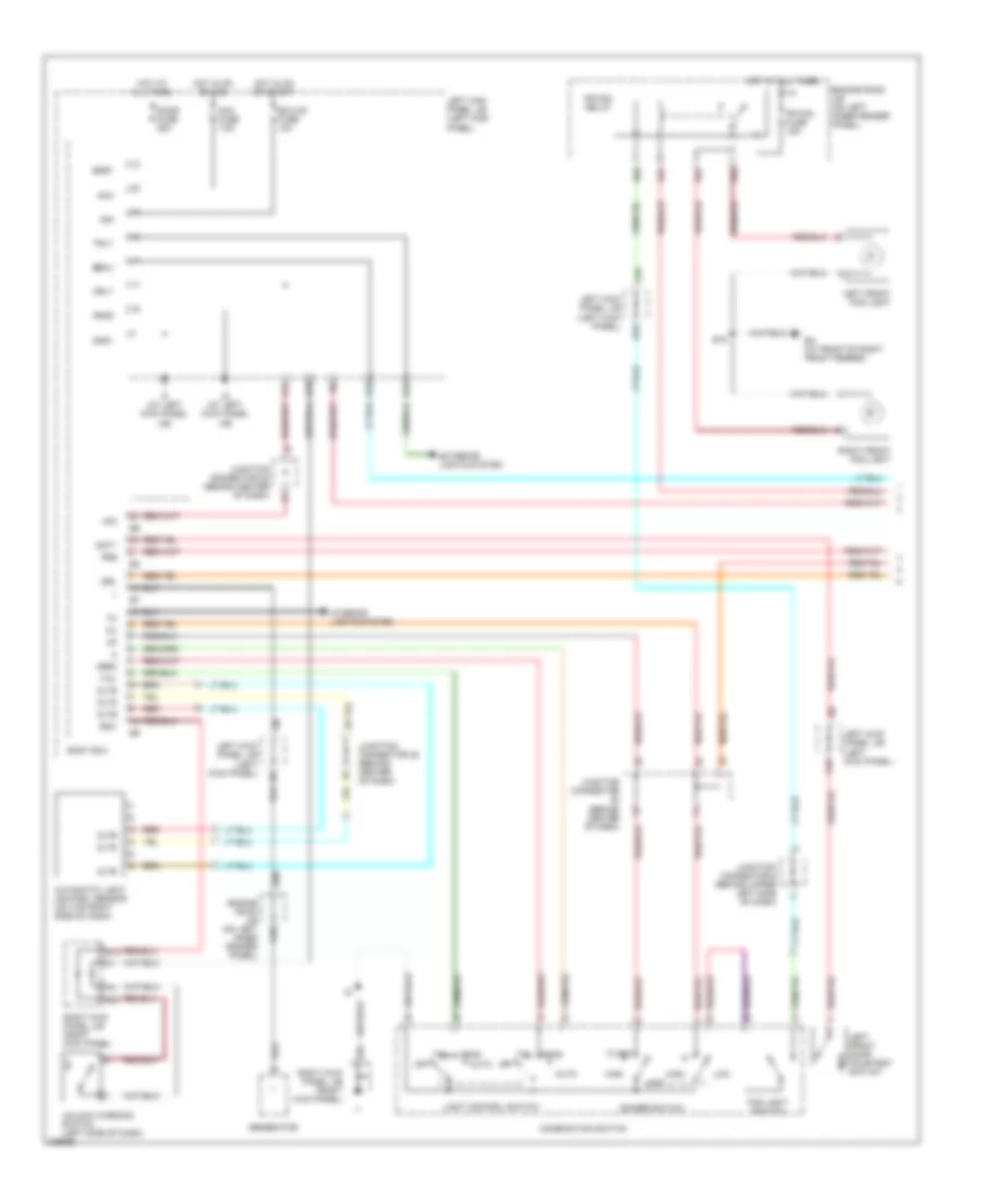
AIR CONDITIONING
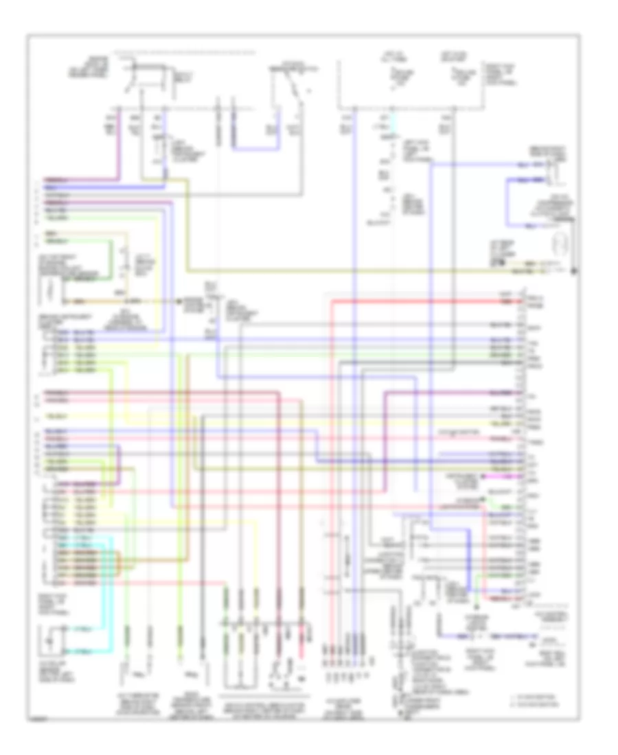
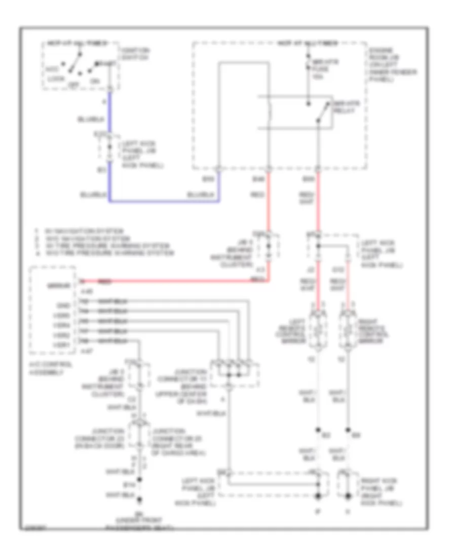
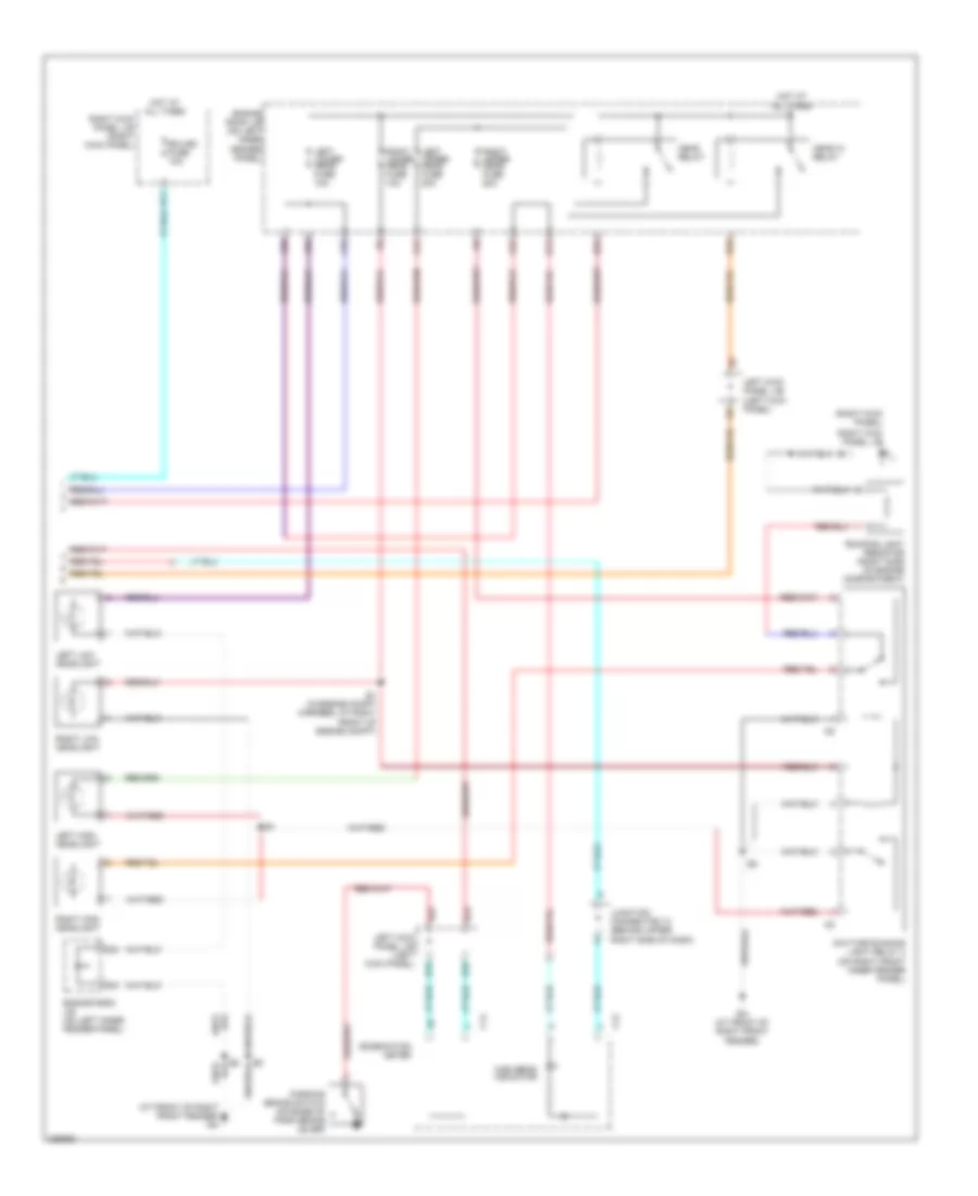
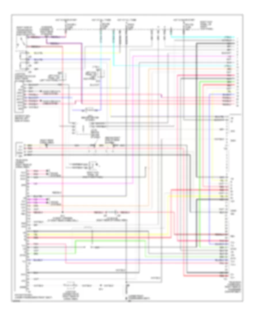
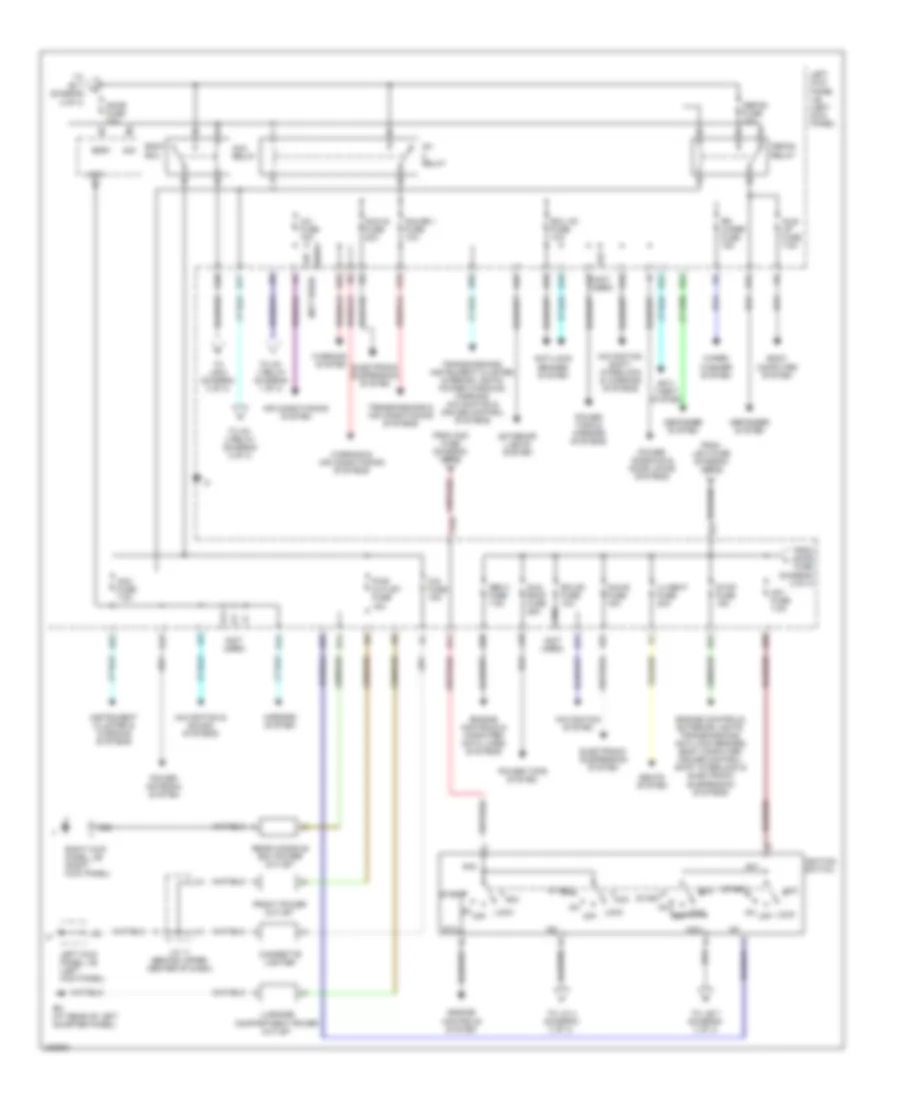
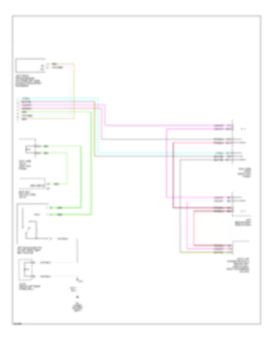
Automatic A/C Wiring Diagram (1 of 2) for Toyota Land Cruiser 2006
 https://portal-diagnostov.com/license.html
Automotive Electricians Portal FZCO
Automotive Electricians Portal FZCO
https://portal-diagnostov.com/license.html
https://portal-diagnostov.com/license.html
Automotive Electricians Portal FZCO
Automotive Electricians Portal FZCO
List of elements for Automatic A/C Wiring Diagram (1 of 2) for Toyota Land Cruiser 2006:
- (behind right side of dash) engine control module
- (in engine compt harness, at left side of engine compartment)
- (left front of engine compt) engine room r/b
- (near right headlight assembly) a/c ambient temperature sensor
- (right kick panel) right kick panel j/b
- A/c control assembly
- A/c fuse 15a
- A/c temp
- A13
- A15
- A25
- A34
- A43
- A45
- Ac1
- Act
- Aif
- Air
- Air inlet control servo motor (behind right side of dash, on heater a/c housing)
- Air vent mode control servo motor (behind left center of dash, on heater a/c housing)
- B/l
- B31
- B32
- B56
- Blower motor controller (behind right side of dash)
- Center cluster integration panel (w/ navigation)
- Clk
- Computer data lines system
- Control circuit
- D17
- D19
- D23
- D29
- Def
- Defc
- Defogger system
- Dpd
- E16
- E18
- Ea (at front of right front fender)
- Engine room j/b (on left inner fender panel)
- F/d
- F18
- Face
- Foot
- Foot/def
- Framc
- Framh
- Frblw
- Frhr
- Fusible link block (on left side of engine compt, near battery)
- Gateway ecu (w/ navigation) (behind left side of dash)
- Gauge 1 fuse 10a
- Gnd
- Gtx+
- Gtx-
- Hot at all times
- Hot in on or start
- Htr fuse 50a
- Htr relay
- J/b 4 (behind center of dash)
- Left kick panel j/b (left kick panel)
- Mfrs
- Mgc
- Mpd1
- Mpd2
- Mpx+
- Mpx-
- Mrec
- Mrrhr
- Multi-display
- N11
- N12
- N14
- N16
- N22
- Navi
- Position switches
- Rdfgr
- Rear a/c circuit
- Red
- Right kick panel j/b (right kick panel)
- Rrmgv
- Stx
- Swd
- Thw
- Thwo
- Tx3+
- Tx3-
- W/ navi- gation
- W/o navi- gation
- W/o navigation
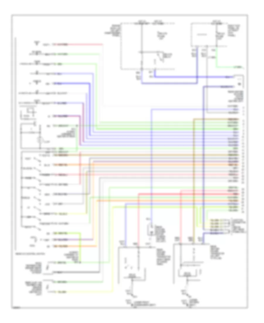
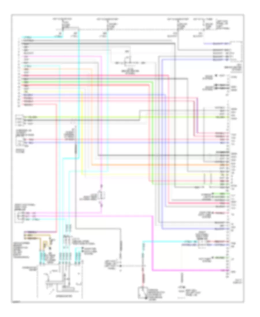
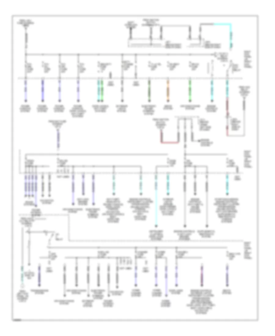
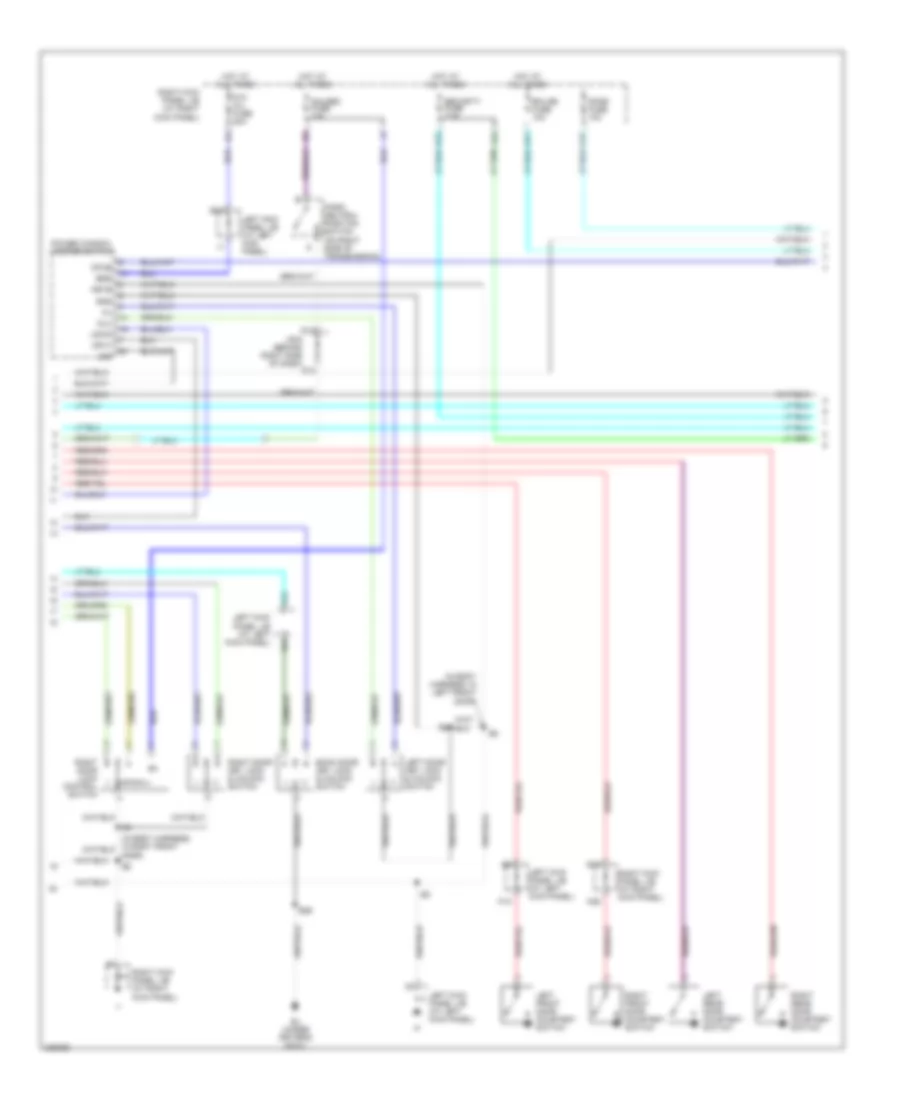
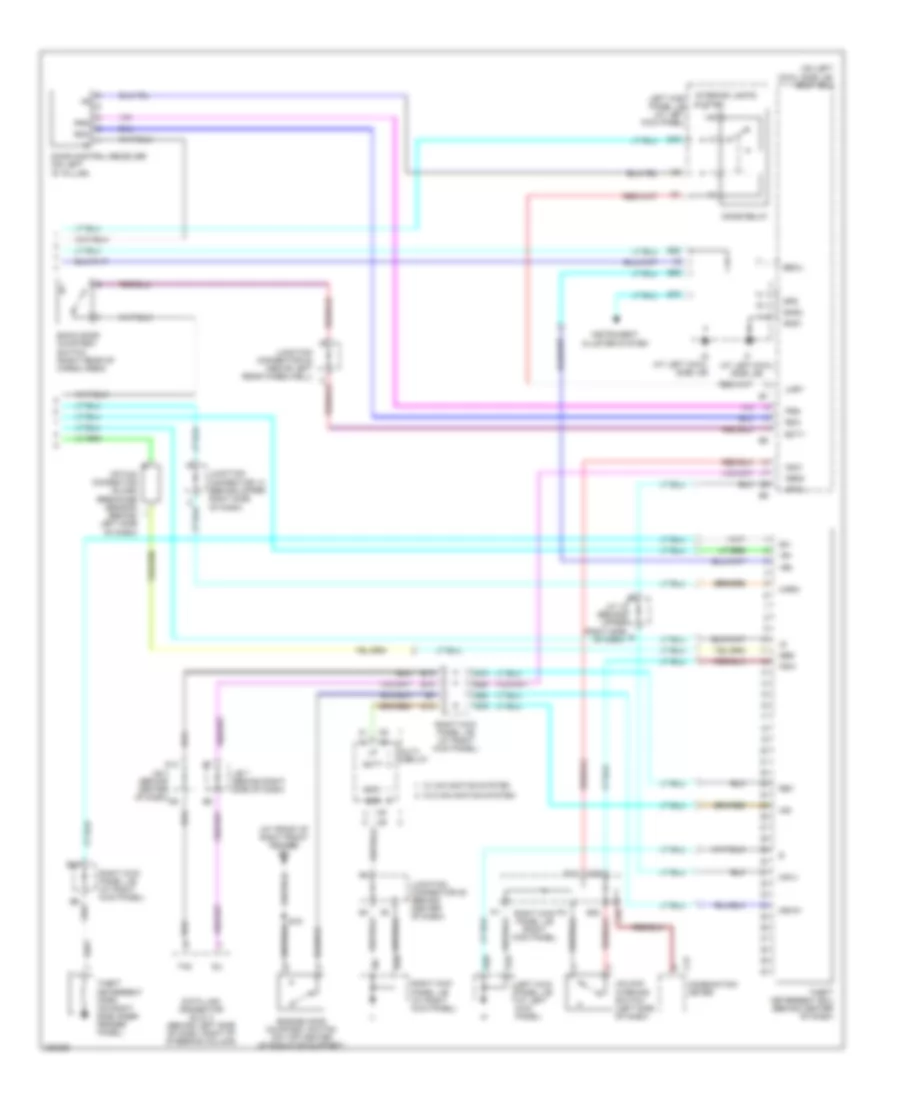
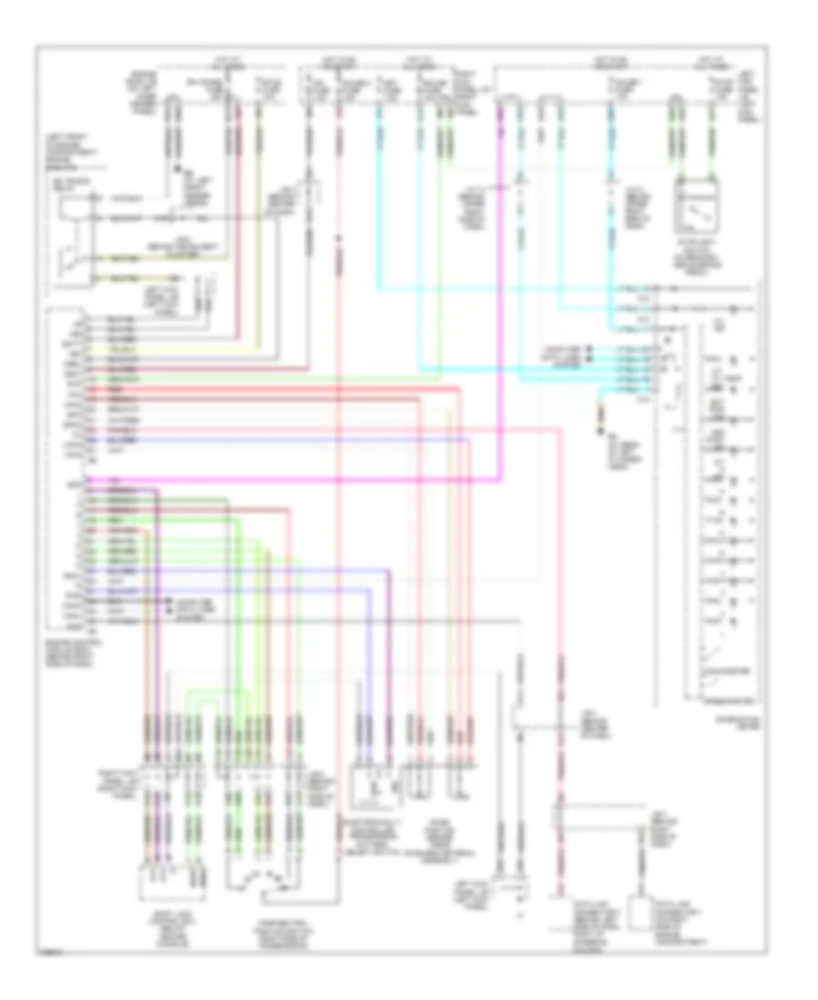
Automatic A/C Wiring Diagram (2 of 2) for Toyota Land Cruiser 2006
List of elements for Automatic A/C Wiring Diagram (2 of 2) for Toyota Land Cruiser 2006:
- (at rear of left cylinder head) ed
- (behind instrument cluster) j/b 5
- (behind right side of dash) j/b 6
- (on a/c
- (on top front of engine) engine coolant temperature sensor
- (under front passenger's seat) bk
- A/c amplifier (rear) (on right side of cargo area)
- A/c control assembly
- A/c dual pressure switch
- A/c magnetic
- A/c solar sensor (on top left side of dash)
- A/c thermistor (behind right side of dash, on evaporator)
- A10
- A17
- A18
- A32
- A46
- A47
- Acan
- Act
- Air mix control servo motor (behind right center of dash, on heater a/c housing)
- B10
- B12
- B13
- B14
- B16
- B26
- B46
- Body ecu (on left kick panel j/b)
- Cid
- Clk
- Clutch & lock
- Compressor)
- Cool
- Csd
- D18
- D22
- D23
- D25
- D28
- D39
- E10 (in engine harness, at rear of engine)
- E19
- E21
- E26
- E30
- Ecu-b2 fuse 10a
- Ecu-ig2 fuse 10a
- Engine controls system
- Engine room j/b (on left inner fender panel)
- F10
- Frcid
- Frclk
- Frcsd
- Frs5
- Frsg
- Frte
- Frtp
- Frtr
- Gnd
- Hot at all times
- Hot in on or start
- Ill+
- Ill-
- Instrument cluster system
- Interior lights system
- J/b 4 (behind center of dash)
- J/b 5 (behind instrument cluster)
- J/c 17 (behind glove box)
- Junction connector 11 (behind upper center of dash)
- Junction connector 23 junction connector 25 (j/c 23: in back door) (j/c 25: right rear of cargo area)
- K19
- K35
- Left kick panel j/b (left kick panel)
- Lock
- Mcool
- Mg clt relay
- Mhot
- N13
- N15
- N19
- Nca
- Pnk
- Psw
- Q22
- Q71
- Q81
- Q83
- Red
- Right kick panel j/b (right kick panel)
- Room temperature sensor (front) (behind left center of dash)
- Sensor
- Spd
- Tam
- Tamo2
- Tpi
- Ver1
- Ver2
- Ver4
- Ver5
- W/ navigation
- W/o navigation
- Warm
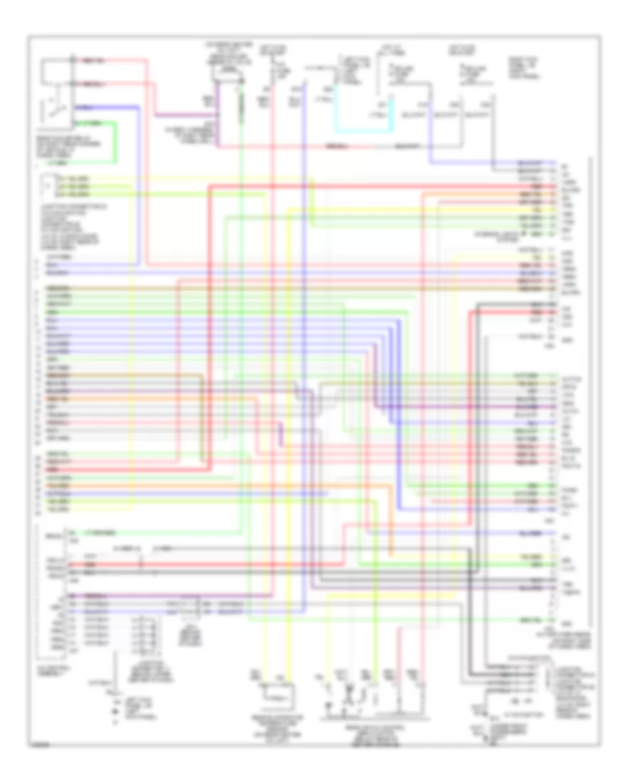
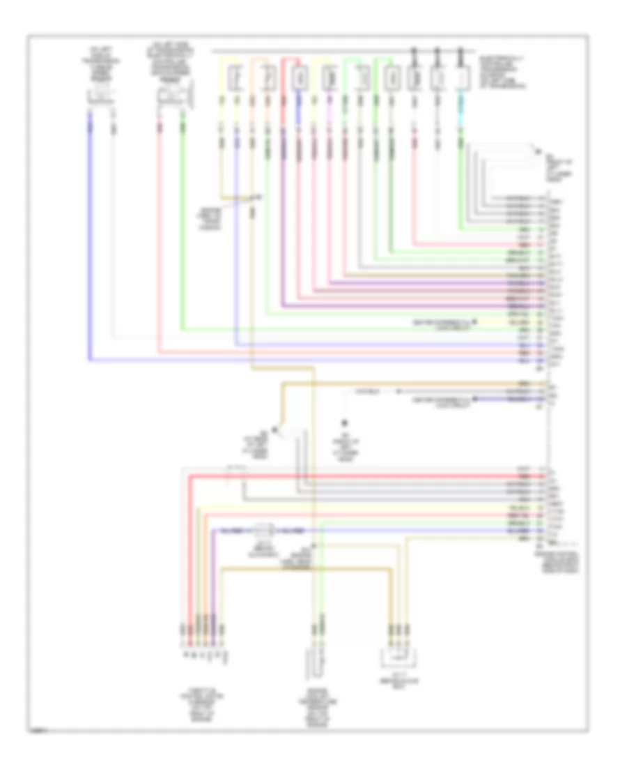
Rear A/C Wiring Diagram (1 of 2) for Toyota Land Cruiser 2006
List of elements for Rear A/C Wiring Diagram (1 of 2) for Toyota Land Cruiser 2006:
- (in body harness, at center of roof) b13
- (under front passenger's seat) bk
- Auto
- Auto-1
- Auto-s
- B/l-i
- B/l-s
- B10
- B13 (in body harness, at center of roof)
- B14
- B52
- B71
- Bi-level
- Cool
- Driver's seat) bj
- Engine room j/b (on left inner fender panel)
- Face
- Face-i
- Face-s
- Foot
- Foot-i
- Foot-s
- Hi-i
- Hi-s
- Hot
- Hot at all times
- Hot in on or start
- Ill
- Illum
- Junction connector (above left rear wheelwell)
- K18
- K42
- Lo-i
- Lo-s
- Me-i
- Me-s
- Middle
- Off
- Off-s
- Rear a/c control switch
- Rear cooler blower motor (in rear heater a/c unit)
- Rear cooler power transistor (right rear of cargo area)
- Rear heater blower motor (in rear heater unit)
- Rear heater power transistor (on left "c" pillar)
- Rear inlet air temperature sensor (on rear heater a/c unit)
- Red
- Right kick panel j/b (at right kick panel)
- Room temperature sensor (rear) (on middle of roof)
- Rr a/c fuse 30a
- Rr htr fuse 10a
- Rr htr relay
- Solid state
- Srg
- T-set
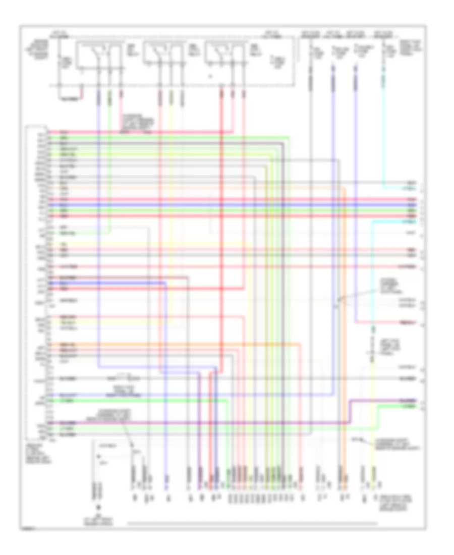
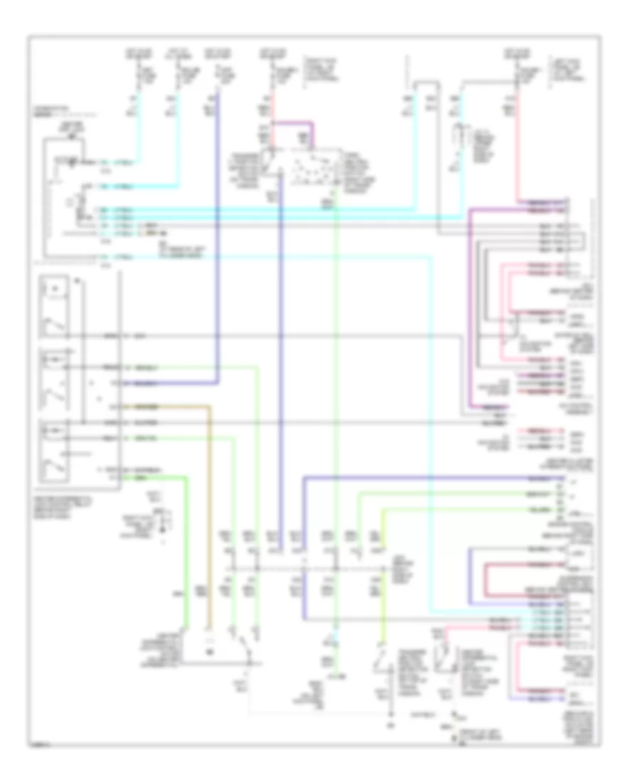
Rear A/C Wiring Diagram (2 of 2) for Toyota Land Cruiser 2006
List of elements for Rear A/C Wiring Diagram (2 of 2) for Toyota Land Cruiser 2006:
- (on rear heater a/c unit) rear cooler magnetic valve
- (under front passenger's seat) bk
- A/c amplifier (rear) (on right side of cargo area)
- A/c control assembly
- A/c fuse 15a
- A18
- A32
- A33
- A34
- A45
- A46
- A47
- Auto-i
- Auto-s
- B/l-i
- B/l-s
- B14
- B19 (in body harness, at right rear wheelwell)
- Blwrc
- Blwrh
- Cid
- Clk
- Cool
- Csd
- E19
- Ecu-b2 fuse 10a
- Ecu-ig2 fuse 10a
- F10
- Face-i
- Face-s
- Foot-i
- Foot-s
- Frcid
- Frclk
- Frcsd
- Gnd
- Hi-i
- Hi-s
- Hot at all times
- Hot in on or start
- Hrrc
- Hrrh
- Ig1
- Ig2
- Ill+
- Ill+2
- Interior lights system
- J/b 4 (behind center of dash)
- J23
- J25
- Junction connector 11 (behind upper center of dash)
- Junction connector 23 (w/o navigation) junction connector 25 (w/ navigation) (j/c 23: in back door) (j/c 25: right rear of cargo area)
- Junction connector 23 junction connector 25 (j/c 23: in back door) (j/c 25: right rear of cargo area)
- K19
- K35
- K39
- Left kick panel j/b (left kick panel)
- Lo-i
- Lo-s
- Mcr
- Me-i
- Me-s
- Mhr
- Nca
- Off-s
- Q22
- Q71
- Rear air mix control servo motor (below rear of center console)
- Rear cooler relay (on right rear corner of vehicle, in cargo area)
- Rear evaporator temperature sensor (on rear heater a/c unit)
- Red
- Right kick panel j/b (right kick panel)
- Rrmgv
- S51
- S52
- Sg1
- Sg2
- Ter
- Tinr
- Tpr
- Trr
- Tsetr
- Ver1
- Ver2
- Ver4
- Ver5
- Vmrc
- Vmrh
- W/ navigation
- W/o navigation
- Warm
ANTI-LOCK BRAKES
Anti-lock Brakes Wiring Diagram (1 of 3) for Toyota Land Cruiser 2006
List of elements for Anti-lock Brakes Wiring Diagram (1 of 3) for Toyota Land Cruiser 2006:
- (in dash harness, at left kick panel)
- (in engine compt harness, at left rear of engine compt)
- (in engine compt harness, at left rear of engine compt) e13
- +bi
- +bo
- A37
- A38
- A39
- A40
- A41
- A44
- Abs & ba & trac & vsc actuator (left rear of engine compt)
- Abs & ba & trac & vsc ecu (behind left side of dash)
- Abs 1 fuse 50a
- Abs 2 fuse 40a
- Abs mtr 1 relay
- Abs mtr 2 relay
- Abs sol relay
- Ast
- B16
- B20
- B22
- Bm1
- Bm2
- D15
- E14
- Ecu-b2 fuse 10a
- Ee (at left front fender apron)
- Engine room r/b (left front of engine compt)
- Fl+
- Fl-
- Fr+
- Fr-
- Fss
- Gauge 2 fuse 10a
- Gnd
- Gnd1
- Gnd2
- Hot at all times
- Hot in on or start
- Ig2
- Ign fuse 7.5a
- Lbl
- Left kick panel j/b (left kick panel)
- Met fuse 7.5a
- Mr1
- Mr2
- Mss
- Mt+
- Mt-
- Mtt
- Nca
- Phg
- Plg
- Pmc
- Pnk
- Q36
- R1+
- R2+
- Red
- Right kick panel j/b (right kick panel)
- Sa1
- Sa2
- Sa3
- Sflh
- Sflr
- Sfrh
- Sfrr
- Srlh
- Srlr
- Srrh
- Srrr
- Str
- Trig
- Vcm
- Wahc
Anti-lock Brakes Wiring Diagram (2 of 3) for Toyota Land Cruiser 2006
List of elements for Anti-lock Brakes Wiring Diagram (2 of 3) for Toyota Land Cruiser 2006:
- (in dash harness, at left kick panel) i2
- B18
- Bat
- C15
- C17
- Combination switch
- D11
- D13
- D31
- D35
- Ecu-ig1 fuse 10a
- Ess
- Gnd
- Hot at all times
- Hot in on or start
- Ig1
- J/b 5 (behind instrument cluster)
- J/b 6 (behind right side of dash)
- Junction connector 2 (behind upper left side of dash)
- Left front abs speed sensor (on left front hub assembly)
- Left kick panel j/b (left kick panel)
- Left rear abs speed sensor (on left rear hub assembly)
- Master cylinder pressure sensor (on master cylinder)
- Nca
- Park/neutral position switch (right side of transmission)
- Pnk
- Q16
- Red
- Right front abs speed sensor (at right front hub assembly)
- Right rear abs speed sensor (on right side of rear hub assembly)
- Ss1+
- Ss1-
- Stop fuse 15a
- Stoplight switch (on bracket, above brake pedal)
- Trig
- Vcc
- Vout
- Vsc warning buzzer (behind left side of dash)
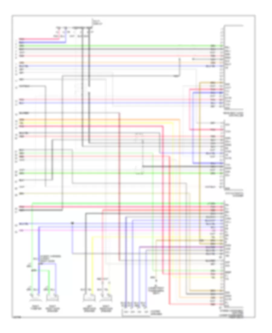
Anti-lock Brakes Wiring Diagram (3 of 3) for Toyota Land Cruiser 2006
List of elements for Anti-lock Brakes Wiring Diagram (3 of 3) for Toyota Land Cruiser 2006:
- A11
- A42
- A43
- Abs & ba & trac & vsc ecu (behind left side of dash)
- Abs ind
- Ahco
- B14
- B18
- Brake ind
- Brl
- C11
- C12
- C13
- C14
- C15
- C17
- C20
- Canh
- Canl
- Combination meter
- Computer data lines system
- Computer data lines system
- D/g
- D27
- D30
- D35
- Data link connector (dlc) 1 (on right side of engine compartment)
- Data link connector (dlc) 3 (behind left side of dash, right of steering column)
- Ed (at rear of left cylinder head)
- Eng+
- Eng-
- Exi
- Exi2
- Flo
- Fro
- Gl1
- Gl2
- Gnd
- Gnd3
- Gnd4
- Gyaw
- Ig1
- Ind
- Ind vsc off
- Ind vsc trac
- Infr
- J/b 5 (behind instrument cluster)
- J/b 7 (behind right side of dash)
- K27
- Left kick panel j/b (left kick panel)
- Mod4
- Nca
- Parking brake switch (on base of park brake lever)
- Pkb
- Q26
- Q27
- Red
- Right kick panel j/b (right kick panel)
- Rl+
- Rl-
- Rr+
- Rr-
- Rss
- Slip ind
- Ss1+
- Ss1-
- Stp
- Suspension control ecu (behind center of dash)
- Trac ind
- Translate ecu
- Transmissions system
- Trc+
- Trc-
- Vscw
- Vys
- Yaw
- Yaw rate sensor (under center of dash, on transmission tunnel)
- Yaw2
- Yss
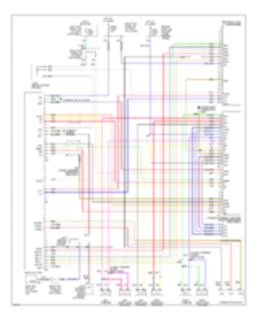
ANTI-THEFT
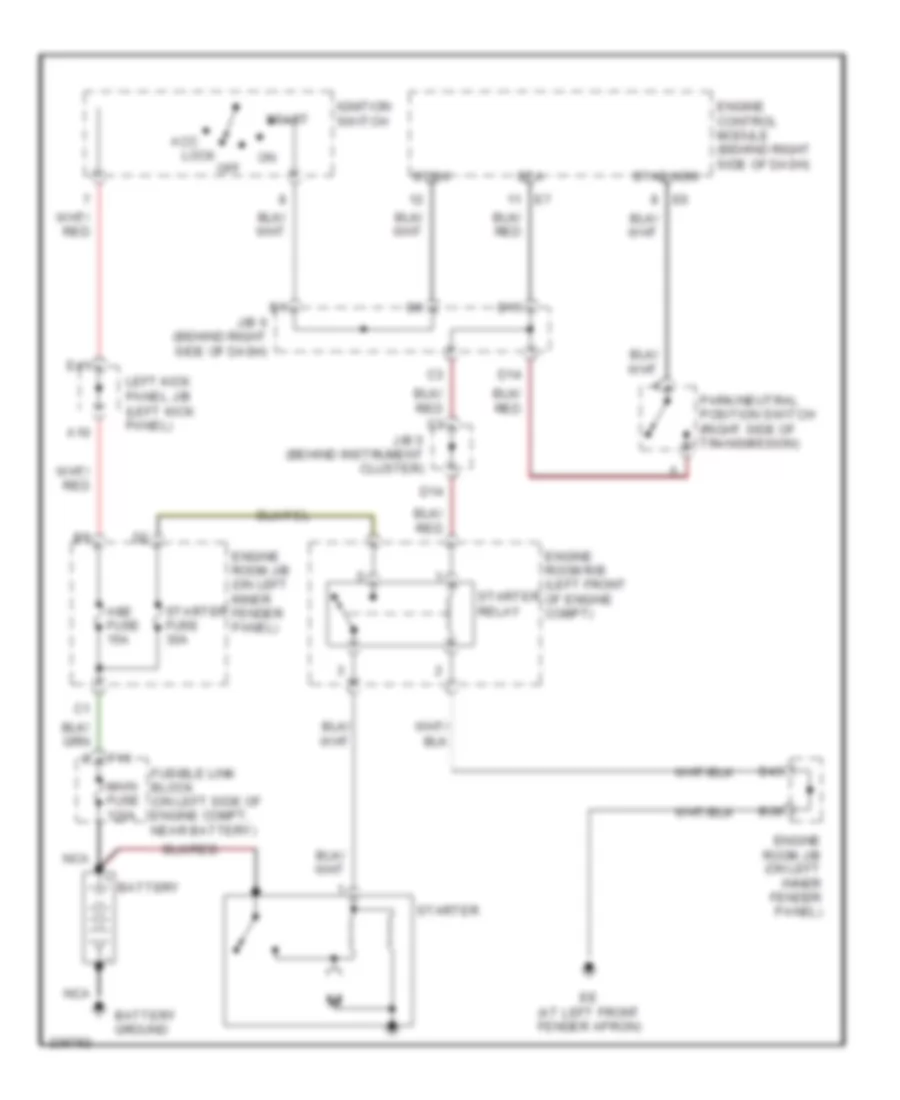
Forced Entry Wiring Diagram (1 of 3) for Toyota Land Cruiser 2006
List of elements for Forced Entry Wiring Diagram (1 of 3) for Toyota Land Cruiser 2006:
- (in body harness, at left front door sill)
- (in body harness, at left rear wheelwell)
- (in body harness, in rear hatch) b15
- (right kick panel) right kick panel j/b
- (under driver's seat) bj
- A40
- Acc
- Acc fuse 7.5a
- Act+
- Act-
- Actd
- B11
- B11 (in body harness, at left rear wheelwell)
- B21
- B22
- B24
- B38
- B49
- B67
- Back door lock motor & door unlock detection switch (right rear of tailgate)
- Bdr1
- Bk (under front passe- nger's seat)
- Body ecu (on left cowl side j/b)
- Dcty
- Door fuse 25a
- E11
- E39
- E40
- E42
- Ecu-ig1 fuse 10a
- Engine room j/b (on left inner fender panel)
- G11
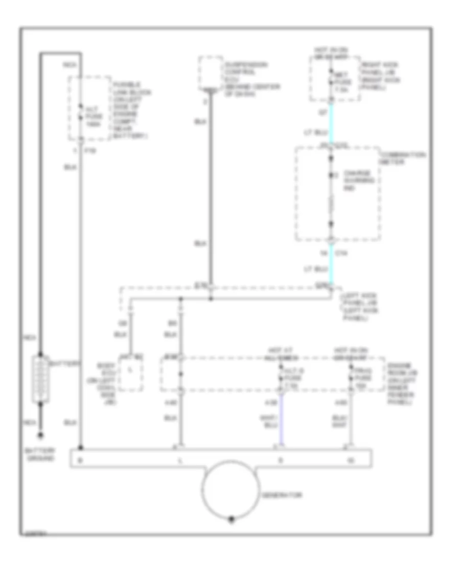
- Generator
- Head relay
- Headlights system
- Horn fuse 10a
- Horn relay
- Horns system
- Hot at all times
- Hot in acc or on
- Hot in on or start
- Hrly
- Idl
- J/b 5 (behind instrument cluster)
- J13
- J14
- Junction connector (above left rear wheelwell)
- Junction connector (behind upper center of dash)
- K25
- K29
- K34
- K38
- K42
- Left front door lock motor & door unlock detection switch (in left front door)
- Left kick panel j/b (left kick panel)
- Left rear door lock motor & door unlock detection switch (in left rear door)
- Lsr
- Lswp
- Mpx1
- Pcty
- Q10
- Q11
- Q21
- Q30
- Q35
- Q41
- Q42
- Right front door lock motor & door unlock detection switch (in right front door)
- Right kick panel j/b (right kick panel)
- Right rear door lock motor & door unlock detection switch (in right rear door)
- Rlcy
- Rrcy
- Sig
- Tail fuse 25a
- Tail relay
- Trly
- Ul1
- Ul2
Forced Entry Wiring Diagram (2 of 3) for Toyota Land Cruiser 2006
List of elements for Forced Entry Wiring Diagram (2 of 3) for Toyota Land Cruiser 2006:
- (in body harness, in left front door)
- B26
- Back door key lock & unlock switch
- Bdr
- Bj (under driver's seat)
- Cpub
- D12
- D13
- Dome fuse 10a
- E15
- E16
- E42
- Ecu-b2 fuse 10a
- Gauge2 fuse 10a
- Gnd
- Hot at all times
- J/b 6 (behind right side of dash)
- K10
- K24
- K26
- Keye
- Kul
- Left door key lock & unlock switch
- Left front door courtesy switch
- Left kick panel j/b (at left kick panel)
- Left rear door courtesy switch
- Lswd
- Mpx1
- P/w (fl) fuse 20a
- Park/ neutral position switch (on right side of transmission)
- Power window master switch
- Q12
- Q17
- Q71
- Q72
- Right door key lock & unlock switch
- Right door lock control switch
- Right front door courtesy switch
- Right kick panel j/b (at right kick panel)
- Right rear door courtesy switch
- Security fuse 7.5a
- Sig
Forced Entry Wiring Diagram (3 of 3) for Toyota Land Cruiser 2006
List of elements for Forced Entry Wiring Diagram (3 of 3) for Toyota Land Cruiser 2006:
- (at front of right front fender) ea
- (on left cowl side j/b) body ecu
- +b1
- +b2
- Back door courtesy switch (right rear of cargo area)
- Bcty
- Becu
- C15
- Combination meter
- D10
- D12
- D14
- Data link connector (dlc) 3 (behind left side of dash, right of steering column)
- Dome relay
- Door control receiver (on left "d" pillar)
- Dswh
- E12
- E13
- E15
- E18
- E20
- E23
- Engine hood courtesy switch (on top center of radiator support)
- Gbs
- Gnd
- Gnd1
- Gnd2
- Horn
- If (at left cowl side j/b)
- Ig (at left cowl side j/b)
- Ind
- Instrument cluster system
- Interior lights
- J/b 4 (behind center of dash)
- J/b 7 (behind right side of dash)
- J/c 14 (behind upper right side of dash)
- Junction connector 14 (behind upper right side of dash)
- Junction connector 22 (above left rear wheelwell)
- Junction connector 28 (behind center of dash)
- Ksw
- Left kick panel j/b (at left kick panel)
- Lmry
- Mpx1
- Mpx3
- Multi- display
- Obd2
- Option connector (glass breakage sensor) (behind left side of dash)
- Prg
- Q20
- Q22
- Q26
- Q46
- Q70
- Q73
- Q74
- Q76
- Q79
- Q82
- Q84
- Rda
- Rev
- Right kick panel j/b (at right kick panel)
- Right kick panel j/b (right kick panel)
- Scty
- Sh-
- Sil
- Spd
- System
- Tac
- Theft deterrent ecu (behind center of dash)
- Theft deterrent horn (on right side inner fender panel)
- Unlock warning switch (left side of dash)
- W/ navigation system
- W/o navigation system
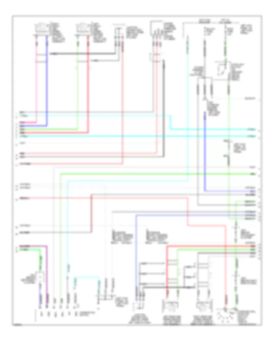
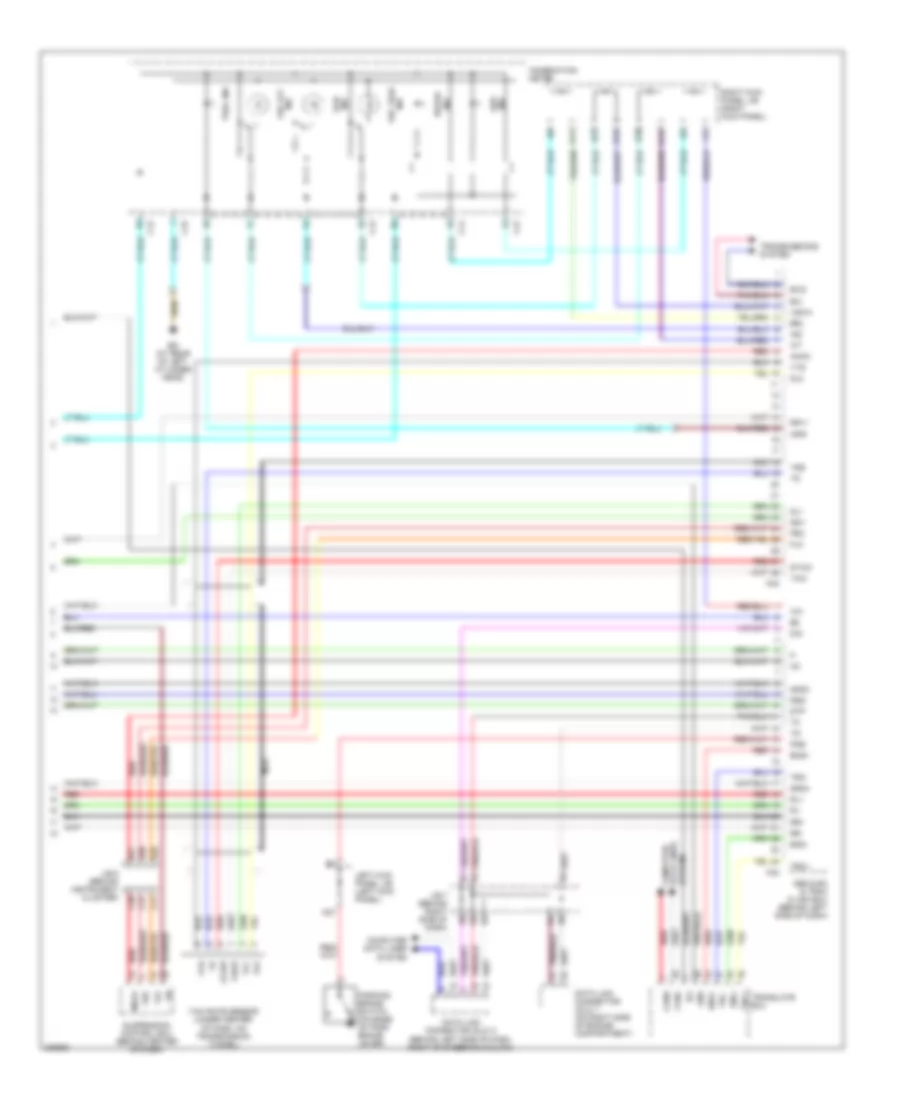
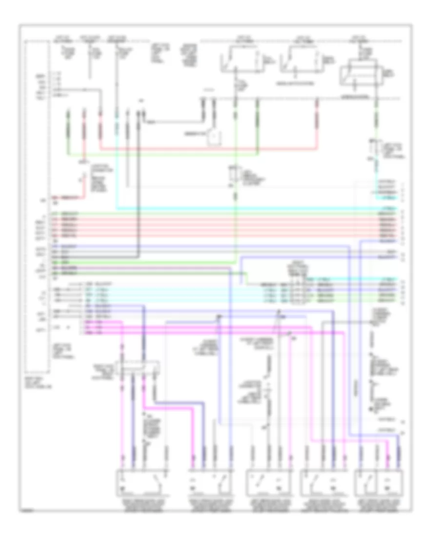
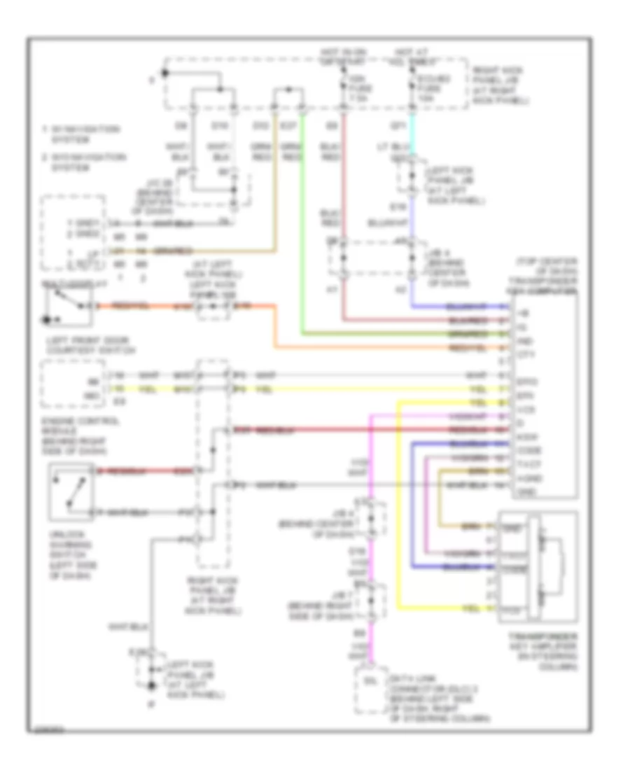
Immobilizer Wiring Diagram for Toyota Land Cruiser 2006
List of elements for Immobilizer Wiring Diagram for Toyota Land Cruiser 2006:
- (at left kick panel) left kick panel j/b
- (top center of dash) transponder key computer
- Agnd
- Ant1
- Ant2
- Code
- Cty
- D10
- D12
- D18
- Data link connector (dlc) 3 (behind left side of dash, right of steering column)
- E16
- E18
- E19
- E23
- E25
- E27
- Ecu-b2 fuse 10a
- Efii
- Efio
- Engine control module (behind right side of dash)
- Gnd
- Gnd1 gnd2
- Hot at all times
- Hot in on or start
- Ign fuse 7.5a
- Imi
- Imo
- Ind
- J/b 4 (behind center of dash)
- J/b 7 (behind right side of dash)
- J/c 28 (behind center of dash)
- K10
- Ksw
- Left front door courtesy switch
- Left kick panel j/b (at left kick panel)
- Lp scty
- M15
- M16
- Multi-display
- Q22
- Q71
- Right kick panel j/b (at right kick panel)
- Sil
- Transponder transponder key amplifier (in steering column)
- Txct
- Unlock warning switch (left side of dash)
- Vc5
- W/ navigation system
- W/o navigation system
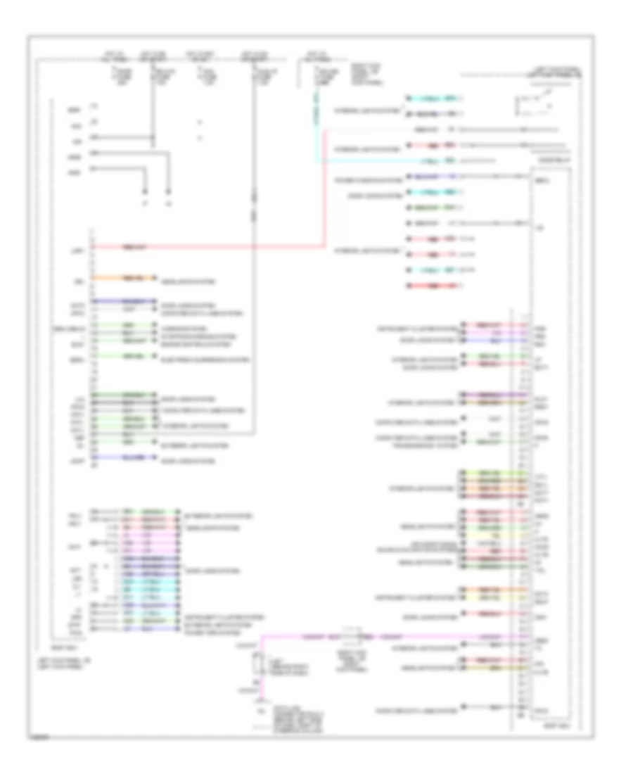
BODY CONTROL MODULES
Body Control Modules Wiring Diagram for Toyota Land Cruiser 2006
List of elements for Body Control Modules Wiring Diagram for Toyota Land Cruiser 2006:
- (left kick panel) left kick panel j/b
- Acan
- Acc
- Acc fuse 7.5a
- Act+
- Act-
- Actd
- Air conditioning, sound & navigation systems
- B24
- Bcty
- Bdr1
- Bdsu
- Becu
- Body ecu
- Cltb
- Clte
- Clts
- Computer data lines system
- D35
- Data link connector (dlc) 3 (behind left side of dash, right of steering column)
- Dbkl/dbklr
- Dcty
- Dcy2
- Dcyl
- Def
- Dome relay
- Door fuse 25a
- Door locks system
- Drl
- Drlp
- E11
- E12
- E15
- E20
- E22
- Ecu-b2 fuse 10a
- Ecu-ig1 fuse 10a
- Electronic suspension system
- Els1
- Engine controls system
- Exterior lights system
- G11
- Gnd1
- Gnd2
- Head
- Headlights system
- Hf2
- Hot at all times
- Hot in acc or on
- Hot in on or start
- Hrly
- Idl
- Idle up fuse 7.5a
- Ile
- Instrument cluster system
- Interior lights system
- J/b 7 (behind right side of dash)
- K22
- K25
- K29
- K38
- K42
- Ksw
- Lcyl
- Left kick panel j/b (left kick panel)
- Lmry
- Lsr
- Lswp
- Mpx1
- Mpx2
- Mpx3
- Mpx4
- Mpx5
- Mpx6
- Obd2
- Pcty
- Pcyl
- Pkb
- Power tops system
- Power windows system
- Prg
- Pws
- Q10
- Q11
- Q22
- Q26
- Q27
- Q70
- Q71
- Q79
- Rcyl
- Rda
- Red
- Right kick panel j/b (right kick panel)
- Rlcy
- Rrcy
- Sig
- Sil
- Spd
- Starting/charging system
- Stp1
- Tail
- Transmissions system
- Trly
- Ul1
- Ul2
- Warning system
COMPUTER DATA LINES
Data Link Connector Wiring Diagram for Toyota Land Cruiser 2006
List of elements for Data Link Connector Wiring Diagram for Toyota Land Cruiser 2006:
- (behind center of dash) theft deterrent ecu
- (behind left side of dash) translate ecu
- (behind right kick panel)
- (right kick panel) right kick panel j/b
- A/b
- A42
- Abs & ba & trac & vsc ecu (behind left side of dash)
- B22
- Bat
- Body ecu (on cowl side j/b)
- C10
- C14
- C26
- Ca1h
- Ca1l
- Canh
- Canl
- Center air bag sensor assembly (behind center of dash)
- Combination meter
- Cowl side j/b rh (right kick panel)
- Cowl side j/b (left kick panel)
- Cowl side j/b (right kick panel)
- Cowl side j/b lh (left kick panel)
- D/g
- D12
- D14
- D18
- D20
- Data link connector (dlc) 1 (on right side of engine compartment)
- Data link connector (dlc) 3 (behind left side of dash, right of steering column)
- E10
- E11
- E12
- E13
- E14
- E17
- E18
- E20
- E21
- Eb (at right front fender apron)
- Ed (at rear of left cylinder head)
- Engine control module (behind right
- F10
- Gateway ecu (behind left side of dash)
- Hot at all times
- Hot in on or start
- Ign fuse 7.5a
- J/b 4 (behind center of dash)
- J/b 7 (behind right side of dash)
- J/c 28 (behind center of dash)
- J/c 29, 30, 31 & 32
- J29
- J30
- J31
- J32
- Multi-display
- Obd 2
- Obd-2 fuse 7.5a
- Q11
- Q14
- Q53
- Q73
- Red
- Rev
- S21
- Side of dash)
- Sil
- Suspension control ecu (behind center of dash)
- T25
- Tac
- Tach canl
- Tire pressure monitor ecu (behind right side of dash)
- Transponder key computer (top center of dash)
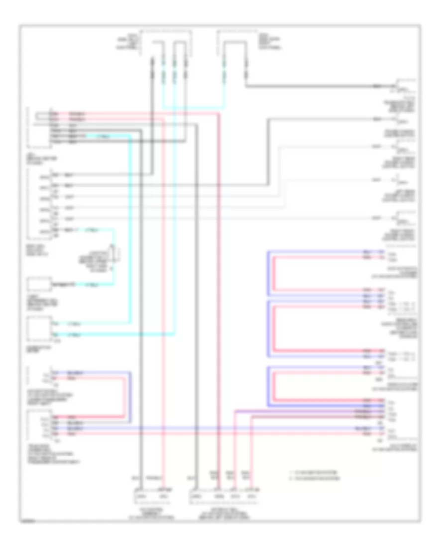
High/Low Bus Wiring Diagram for Toyota Land Cruiser 2006
List of elements for High/Low Bus Wiring Diagram for Toyota Land Cruiser 2006:
- A/c control assembly (w/ navigation system)
- A10
- A45
- Body ecu (on cowl side j/b lh)
- C12
- C15
- Combination meter
- Connector 14 (behind upper
- Cowl side j/b lh (left kick panel)
- Cowl side j/b rh (right kick panel)
- D41
- Dvd automatic changer (w/ navigation system)
- E24
- Gateway ecu (w/ navigation system) (behind left side of dash)
- Gtx+
- Gtx-
- J/b 4 (behind center of dash)
- Junction
- Left rear power window control switch
- Mpd1
- Mpd2
- Mpx+
- Mpx-
- Mpx1
- Mpx2
- Mpx3
- Mpx4
- Mpx5
- Mpx6
- Multi-display (w/ navigation system)
- Navigation ecu (w/ navigation system) (under passengers front seat)
- Of dash)
- Pnk
- Power window master switch
- Q37
- Q66
- R37
- R38
- Radio & player (w/ navigation system)
- Rear seat audio controller (in rear of center floor console)
- Right front power window control switch
- Right rear power window control switch
- Right side
- T21
- Television camera ecu (w/ navigation system) (right rear of passenger compartment)
- Theft deterrent ecu (behind center of dash)
- Tilt & telescopic ecu (behind left side of dash)
- Tx+
- Tx-
- Tx1+
- Tx1-
- Tx3+
- Tx3-
- Txm+
- Txm-
- W/ navigation system
- W/o navigation system
CRUISE CONTROL
Cruise Control Wiring Diagram for Toyota Land Cruiser 2006
List of elements for Cruise Control Wiring Diagram for Toyota Land Cruiser 2006:
- (behind left side of dash, right of steering column) data link connector (dlc) 3
- (left front of engine compartment) engine room r/b
- (on right side of engine compt) data link connector (dlc) 1
- +b2
- +bm
- +res
- -set
- A43
- Accel position sensor (near accelerator pedal assembly)
- B11
- B39
- B44
- Batt
- C11
- C12
- C15
- C18
- C19
- Cancel
- Canh
- Canl
- Ccs
- Combination meter
- Combination switch
- Computer data lines system
- Cruise
- Cruise control switch
- D12
- D15
- D22
- D27
- D31
- D35
- D36
- E01
- E02
- E03
- E04
- E05
- E10
- E10 (in engine harness, at rear of engine)
- E14
- E15
- E21
- E26
- E28
- Ea (at front of right front fender)
- Ecu-b2 fuse 10a
- Ed (at rear of left cylinder head)
- Ee (at left front fender apron)
- Efi or ecd 1 fuse 25a
- Efi or ecd relay
- Engine control module (behind right side of dash)
- Engine room j/b (on left inner fender panel)
- Eo (front of left cylinder head)
- Eom
- Ep1
- Ep2
- Epa
- Epa2
- Etcs fuse 10a
- Gauge 1 fuse 10a
- Gauge 2 fuse 10a
- Ge01
- Gnd
- Hot at all times
- Hot in on or start
- Ign fuse 7.5a
- Igsw
- Ind
- J/b 4 (behind center of dash)
- J/b 4 (behind center of dash) d8
- J/b 5 (behind instrument cluster)
- J/b 6 (behind right side of dash)
- J/b 7 (behind right side of dash)
- J/c 17 (behind glove box)
- J/c 29 & 32 (behind right kick panel)
- J29
- J32
- Junction connector (behind upper right side of dash)
- Junction connector 14 (behind upper right side of dash)
- Left kick panel j/b (left kick panel)
- Me01
- Met fuse 7.5a
- Mpx2
- Mrel
- Nca
- On/off
- Output
- Park/neutral position switch (right side of transmission)
- Q44
- Q65
- Q70
- Red
- Right kick panel j/b (right kick panel)
- Spd
- Speedometer
- St1-
- Stop fuse 15a
- Stoplight switch (on bracket, above brake pedal)
- Stp
- Throttle control motor & sensor (on top front of engine)
- Vcc
- Vcp1
- Vcp2
- Vcpa
- Vehicle speed sensor (combination meter) (on left side of transmission)
- Vpa
- Vpa1
- Vpa2
- Vta
- Vta1
- Vta2
DEFOGGERS
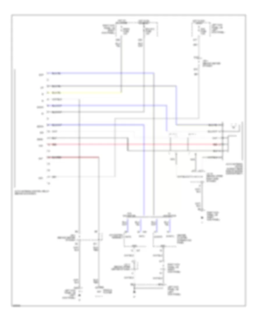
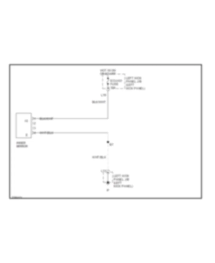
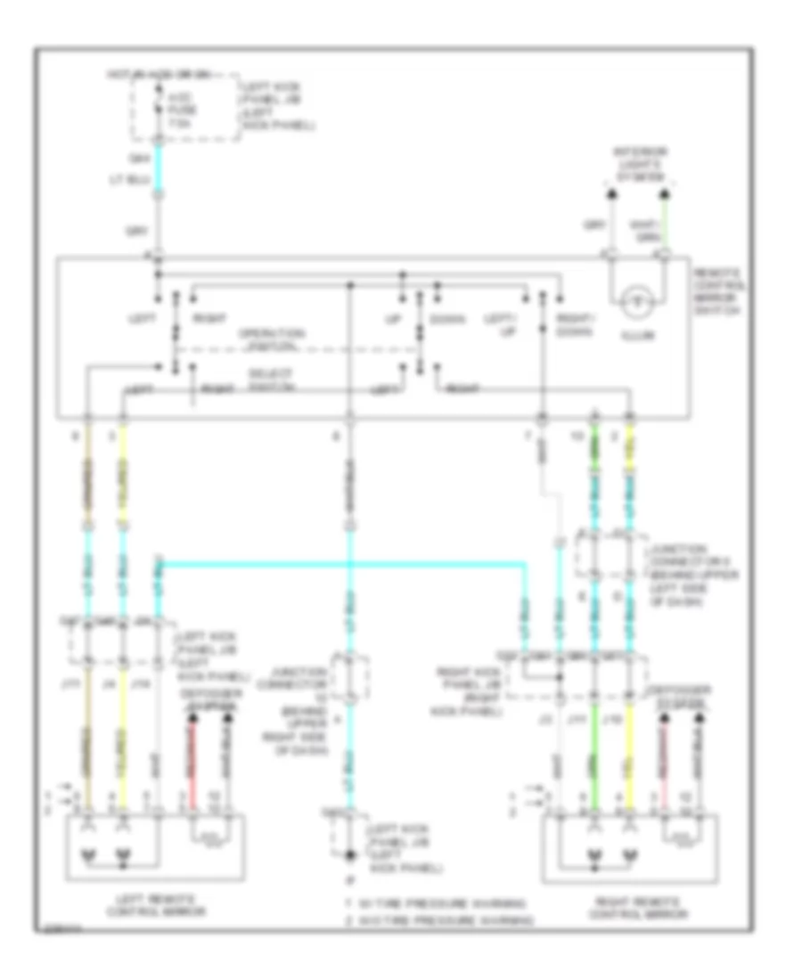
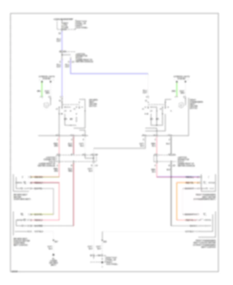
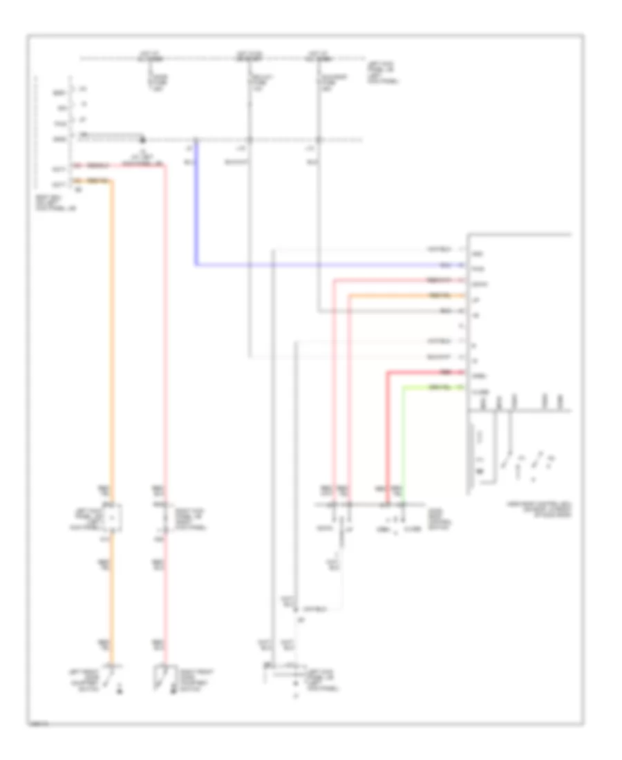
Heated Mirrors Wiring Diagram for Toyota Land Cruiser 2006
List of elements for Heated Mirrors Wiring Diagram for Toyota Land Cruiser 2006:
- w/ navigation system
- w/o navigation system w/ tire pressure warning system w/o tire pressure warning system
- A/c control assembly
- A45
- A47
- Acc
- B14
- B48
- B50
- B66
- Bk (under front passenger's seat)
- D20
- E37
- Engine room j/b (on left inner fender panel)
- F10
- G12
- Gnd
- Hot at all times
- Ignition switch
- J/b 5 (behind instrument cluster)
- Junction connector 11 (behind upper center of dash)
- Junction connector 23 (in back door)
- Junction connector 25 (right rear of cargo area)
- Left kick panel j/b (left kick panel)
- Left remote control mirror
- Lock
- Mir htr fuse 15a
- Mir htr relay
- Mrrhr
- Off
- Red
- Right kick panel j/b (right kick panel)
- Right remote control mirror
- Start
- Ver1
- Ver2
- Ver4
- Ver5
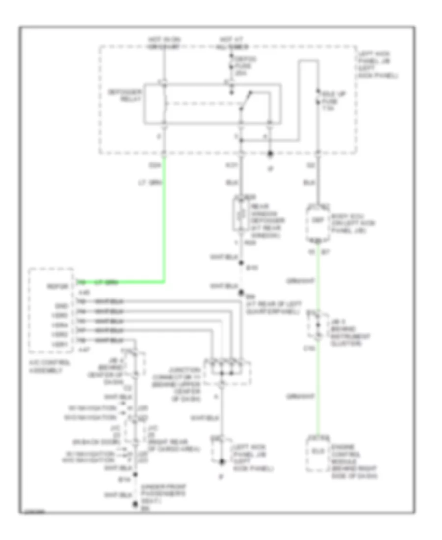
Rear Defogger Wiring Diagram for Toyota Land Cruiser 2006
List of elements for Rear Defogger Wiring Diagram for Toyota Land Cruiser 2006:
- (under front passenger's seat) bk
- A/c control assembly
- A45
- A47
- B14
- B15
- Bm (at rear of left quarterpanel)
- Body ecu (on left kick panel j/b)
- C10
- D24
- Def
- Defog fuse 20a
- Defogger relay
- Els
- Engine control module (behind right side of dash)
- Esl1
- F j23
- F10
- Gnd
- H j25
- Hot at all times
- Hot in on or start
- Idle up fuse 7.5a
- J/b 4 (behind center of dash)
- J/b 5 (behind instrument cluster)
- J/c (in back door)
- J/c (right rear of cargo area)
- J23
- J25 h f
- Junction connector 11 (behind upper center of dash)
- K31
- Left kick panel j/b (left kick panel)
- R28
- R29
- Rdfgr
- Rear window defogger (at rear window)
- Ver1
- Ver2
- Ver4
- Ver5
- W/ navigation
- W/ navigation w/o navigation
- W/o navigation
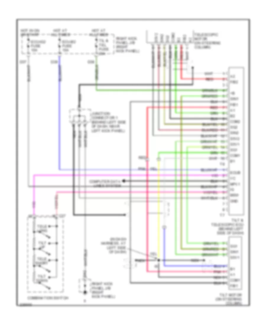
ELECTRONIC POWER STEERING
Electronic Power Steering Wiring Diagram for Toyota Land Cruiser 2006
List of elements for Electronic Power Steering Wiring Diagram for Toyota Land Cruiser 2006:
- (in dash harness, at left side of dash)
- A nca
- C17
- Com1
- Com2
- Combination switch
- Computer data lines system
- D42
- Ecu-b2 fuse 10a
- Ecu-ig2 fuse 10a
- Ecub
- F/b1
- F/b2
- Gnd
- Hot at all times
- Hot in on or start
- Junction connector 1 (behind left side of dash, near left kick panel)
- Mpx1
- Msw
- Nca
- Pnk
- Red
- Right kick panel j/b (right kick panel)
- S5v1
- S5v2
- Sg1
- Sg2
- Sin1
- Sin2
- Tele long
- Tele short
- Telescopic motor (on steering column)
- Til & tel fuse 20a
- Tilt & telescopic ecu (behind left side of dash)
- Tilt down
- Tilt motor (on steering column)
- Tilt up
ELECTRONIC SUSPENSION
Electronic Suspension Wiring Diagram (1 of 2) for Toyota Land Cruiser 2006
List of elements for Electronic Suspension Wiring Diagram (1 of 2) for Toyota Land Cruiser 2006:
- (on bracket, above brake pedal) stoplight switch
- Ahc fuse 50a
- Ahc main relay (behind left side of dash)
- Ahc relay
- Ahc-b fuse 15a
- Ahc-ig fuse 20a
- B39
- B42
- Bm (at rear of left quarterpanel)
- Computer data lines system
- D18
- D21
- D31
- D35
- Dnsw
- Door
- E19
- E32
- E33
- E34
- E35
- Ee (at left front fender apron)
- Engine room j/b (on left inner fender panel)
- Engine room r/b (left front of engine compt)
- Exi
- Fa+
- Fa-
- Fb+
- Fb-
- Flo
- Fro
- Gauge 1 fuse 10a
- Gnd
- Hot at all times
- Hot in on or start
- J/b 5 (behind instrument cluster)
- J/c 3 (behind upper left side of dash)
- J/c 8 (behind upper center of dash)
- L4sw
- Left front damping force control actuator (left kick panel)
- Left kick panel j/b (left kick panel)
- Left rear damping force control actuator (near left "b" pillar)
- Mod2
- Mod4
- Mrly
- Nsw
- Pacc
- Q65
- Ra+
- Ra-
- Rb+
- Rb-
- Red
- Reg
- Right front damping force control actuator (right kick panel)
- Right kick panel j/b (right kick panel)
- Right rear damping force control actuator (near right "b" pillar)
- S20
- S21
- S22
- Shb
- Shfl
- Shfr
- Shg
- Shrr
- Sil
- Slac
- Slb
- Slfg
- Slfl
- Slrg
- Slrl
- Ss2+
- Ss2-
- Starting/charging system
- Stop fuse 15a
- Stp
- Suspension control ecu (behind center of dash)
- Toil
- Transmissions system
- Tsw1
- Tsw2
- Upsw
Electronic Suspension Wiring Diagram (2 of 2) for Toyota Land Cruiser 2006
List of elements for Electronic Suspension Wiring Diagram (2 of 2) for Toyota Land Cruiser 2006:
- (at rear of left cylinder head) ed
- A43
- Abs & ba & trac & vsc ecu (behind left side of dash)
- Accumulator solenoid (under driver's seat)
- Ahc pump motor (right rear of engine compt)
- Ahco
- B16
- Body ecu (on cowl side j/b lh)
- C11
- C12
- C13
- C14
- C15
- C16
- C17
- C18
- C19
- C20
- Combination meter
- Combination switch
- Control valve assembly (left rear corner of engine compt)
- D15
- D22
- D27
- D28
- D29
- D30
- D31
- D33
- D34
- D35
- D36
- D37
- Damping mode select switch & height control switch
- Ecu-b2 fuse 10a
- Flo
- Fluid pressure sensor (right rear of engine compt)
- Fro
- Gnd
- Hi ind
- Hot at all times
- J/b 4 (behind center of dash)
- J/b 5 (behind instrument cluster)
- J/b 7 (behind right side of dash)
- J/c 14 (behind upper right side of dash)
- Junction connector 8 (behind upper center of dash)
- Left front height control sensor (left side of engine compt)
- Left kick panel j/b (left kick panel)
- Lo ind
- N ind
- Off ind
- Q22
- Q44
- Rear height control sensor (near rear axle)
- Red
- Right front height control sensor (right side of engine compt)
- Right kick panel j/b (right kick panel)
- Shb
- Shfl
- Shfr
- Shg
- Shrr
- Ss2+
- Ss2-
- Temperature sensor (ahc) (right rear of engine compt)
- Vcc
- Vout
- Wahc
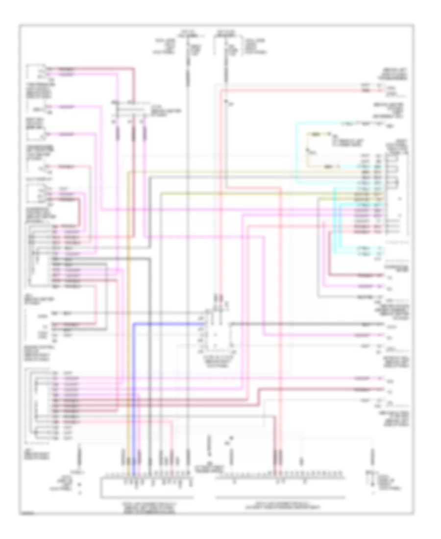
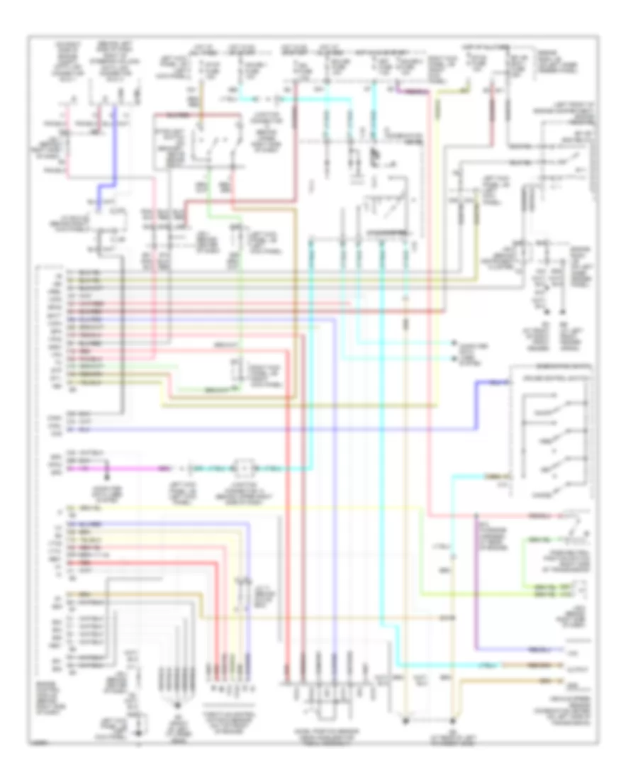
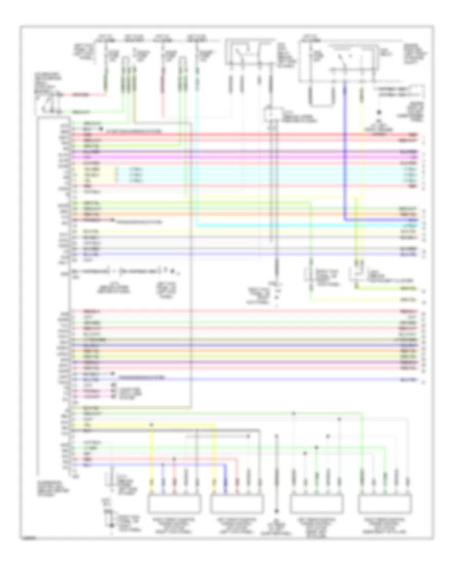
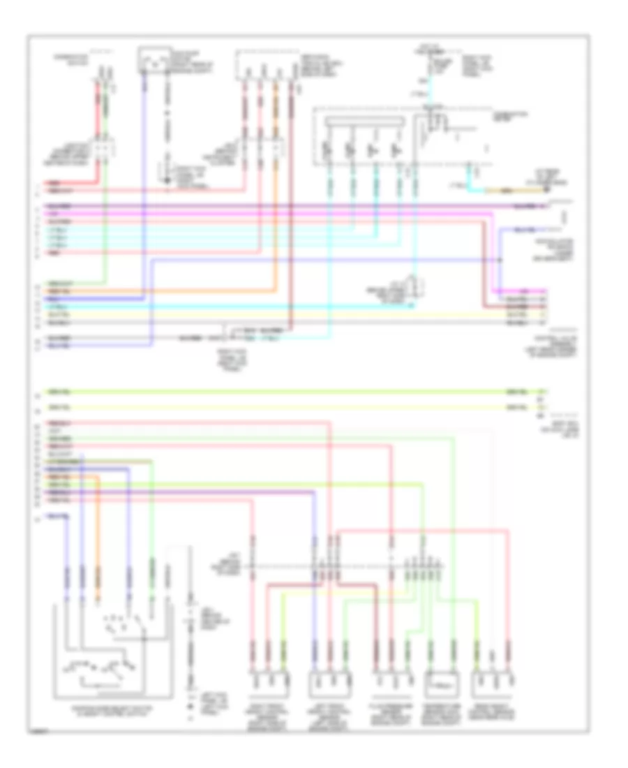
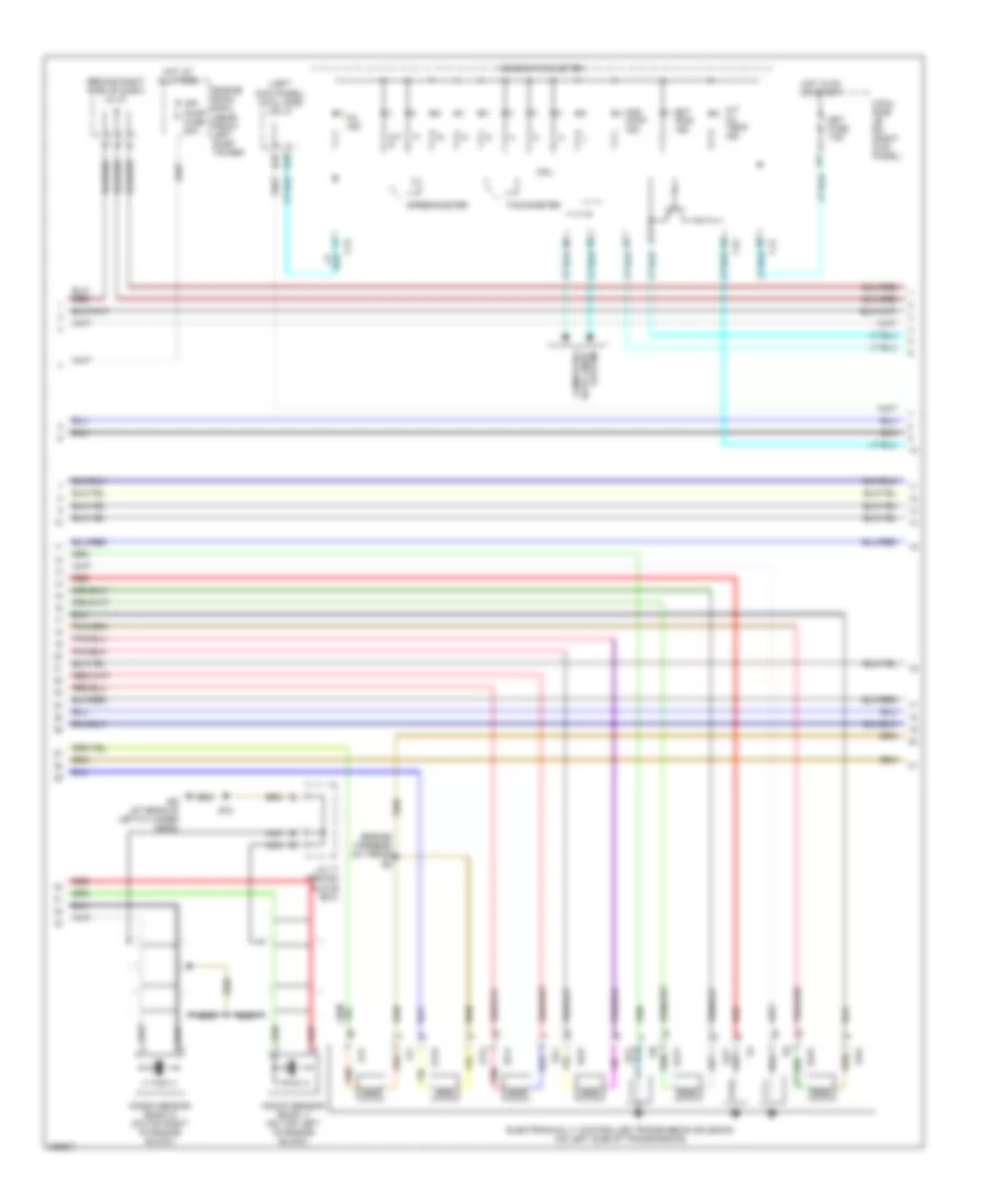
ENGINE PERFORMANCE
4.7L
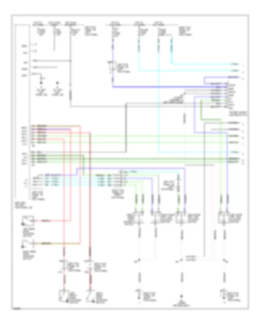
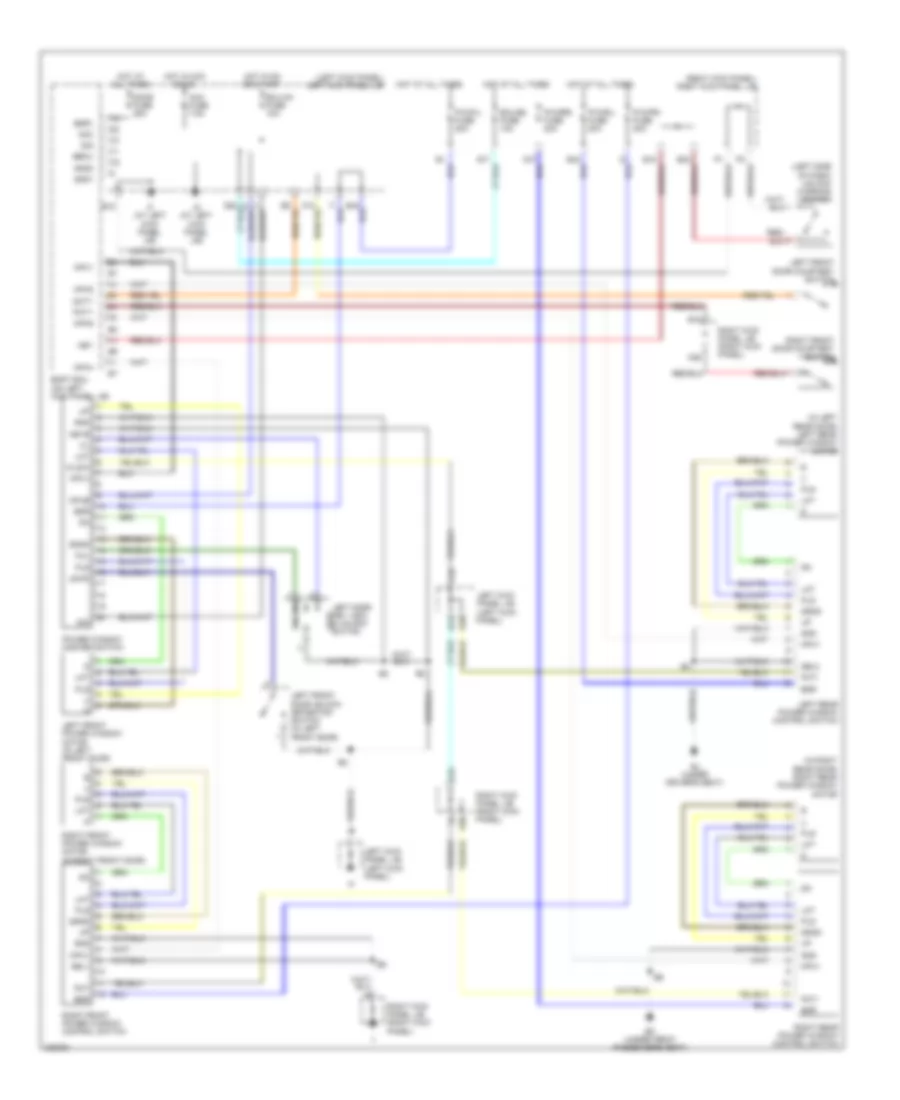
4.7L, Engine Performance Wiring Diagram (1 of 6) for Toyota Land Cruiser 2006
List of elements for 4.7L, Engine Performance Wiring Diagram (1 of 6) for Toyota Land Cruiser 2006:
- #10
- #20
- #30
- #40
- #50
- #60
- (at rear of left cylinder head) ed
- (engine harn, at left of engine)
- (on left front of engine) crankshaft position sensor
- (on top left side of engine) camshaft position sensor
- (right kick panel) cowl side j/b rh.
- (top left of engine) injectors
- (top right of engine) injectors
- +b2
- A52
- A53
- Accel position sensor (near accelerator pedal assembly)
- Accr
- Aidi
- Air injection control driver (left side of engine compartment)
- Air pump (top center of engine)
- Air switching valve (top center of engine)
- Airp
- Airv
- B10
- Batt
- Bm+
- Computer data lines system
- Cowl side j/b lh. (left kick panel)
- D10
- D11
- D12
- D31
- D34
- D35
- D36
- E10
- E11
- E14
- E26
- Ee (at left front fender apron)
- Efi or ecd 2 fuse 10a
- En (top center of engine)
- Engine control module (ecm) (behind right side of dash)
- Ep1
- Ep2
- Epa
- Epa2
- Fpr
- G2+
- G2-
- Hot at all times
- Igsw
- J/b 5 (behind instrument cluster)
- J/b 6 (behind right side of dash)
- J/c 17 (behind glove box)
- K16
- Mpmp
- Mrel
- Nca
- Ne+
- Ne-
- Oc1+
- Oc1-
- Oc2+
- Oc2-
- Ppmp
- Q45
- Red
- Sip
- Siv
- Sta
- Starting/charging system
- Stop fuse 15a
- Stop light switch (on bracket, above brake pedal)
- Stp
- Stsw
- Vcp1
- Vcp2
- Vcpa
- Vpa
- Vpa1
- Vpa2
- Vpmp
- Vv1+
- Vv1-
- Vv2+
- Vv2-
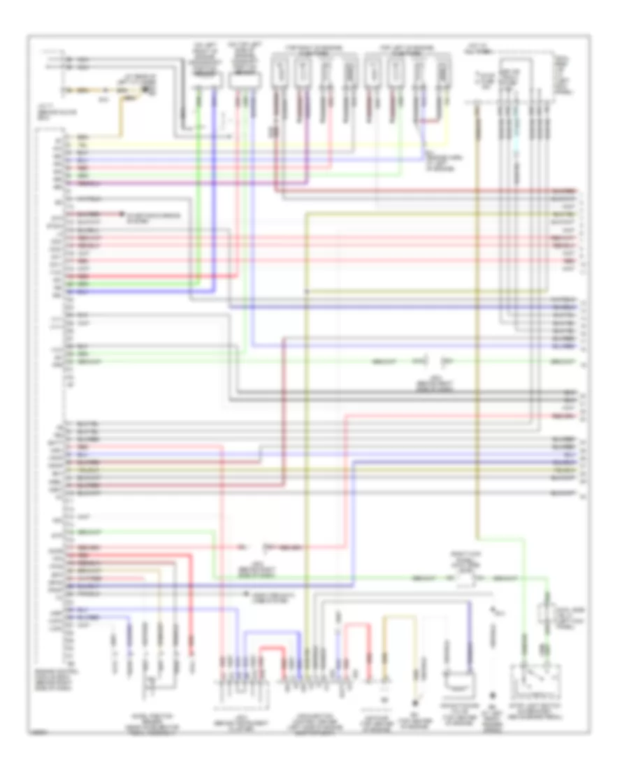
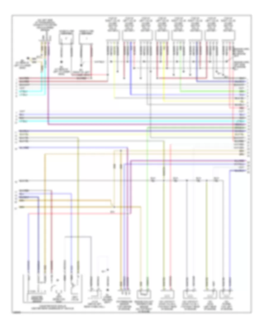
4.7L, Engine Performance Wiring Diagram (2 of 6) for Toyota Land Cruiser 2006
List of elements for 4.7L, Engine Performance Wiring Diagram (2 of 6) for Toyota Land Cruiser 2006:
- (at rear of left cylinder head)
- (behind glove box) j/c 17
- (behind instrument cluster) j/b 5
- (engine harness, left rear of engine compt) e14
- (top left side of engine) left crankshaft position sensor 2
- (top right side of engine) right crankshaft position sensor 2
- Af+
- Af-
- Air fuel ratio sensor (bank 1 sensor 1) (rear of left cylinder bank)
- Air fuel ratio sensor (bank 2 sensor 1) (rear of right cylinder bank)
- C/opn relay
- Cowl side j/b lh. (left kick panel)
- D13
- D15
- D16
- E10
- E13
- E16 (engine harness, left side of engine compt)
- Ea (front of right front fender)
- Ed (at rear of left cylinder head)
- Efi or ecd relay
- Engine room r/b (left front of engine compt)
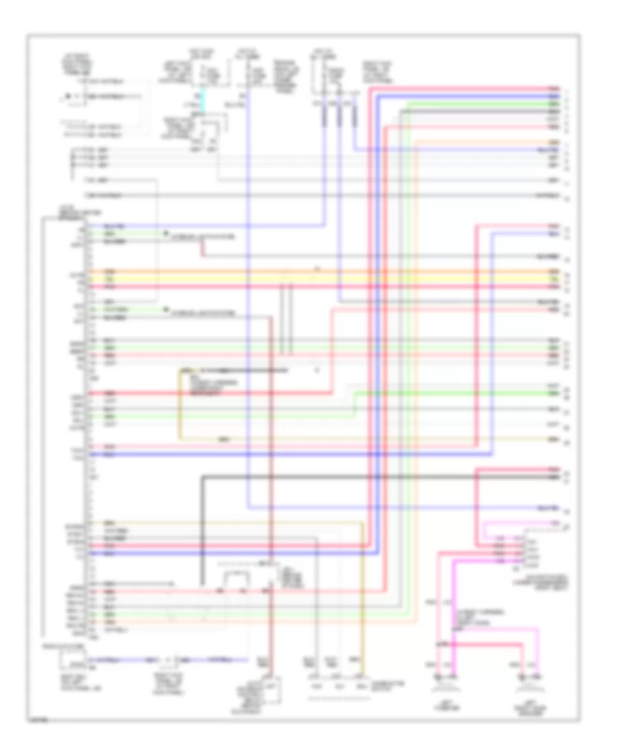
- Fuel pump (in fuel tank)
- Fuel pump relay
- Fuel pump resistor (on right side of engine compt)
- Heated oxygen sensor (bank 1 sensor 2) (on exhaust pipe, left underside of vehicle)
- Heated oxygen sensor (bank 2 sensor 2)
- J/c 17 (behind glove box)
- K23
- Left camshaft timing oil control valve (top left front of engine)
- Nca
- Red
- Right camshaft timing oil control valve (top right front of engine)
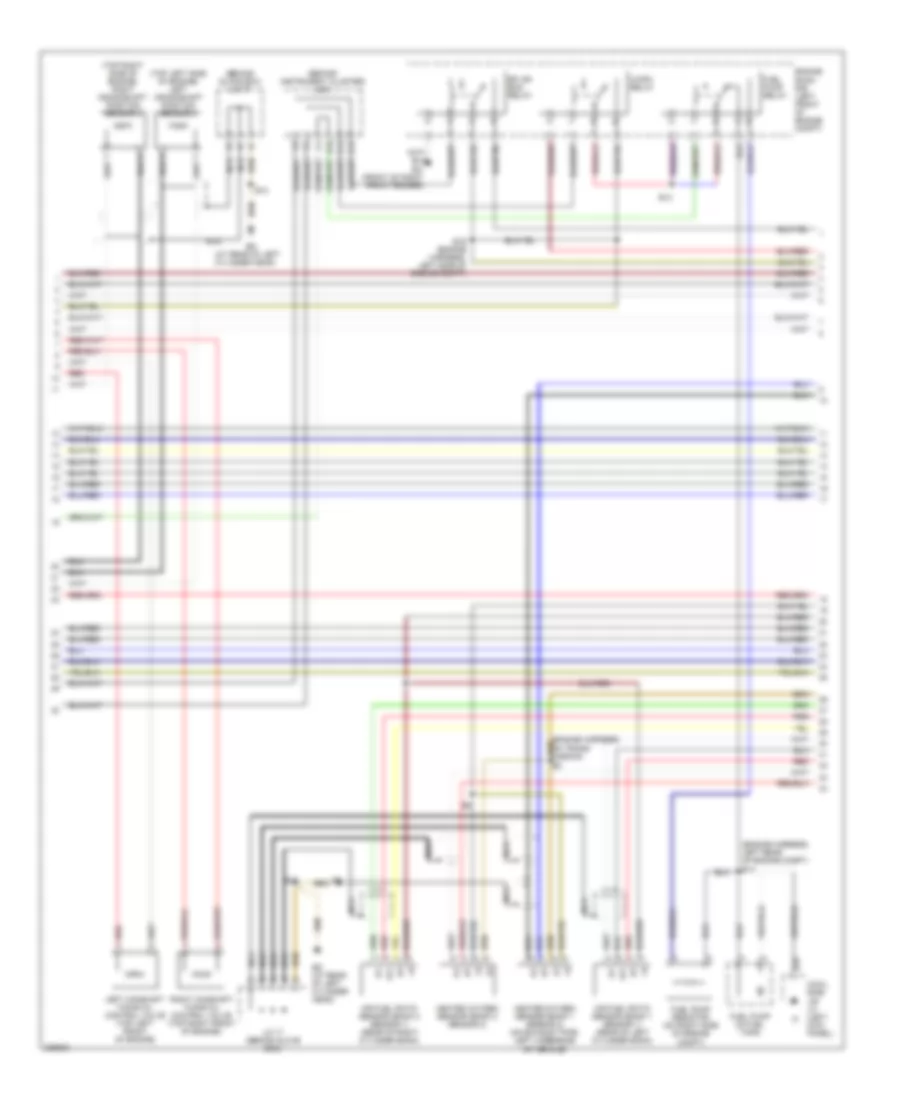
4.7L, Engine Performance Wiring Diagram (3 of 6) for Toyota Land Cruiser 2006
List of elements for 4.7L, Engine Performance Wiring Diagram (3 of 6) for Toyota Land Cruiser 2006:
- (at left front fender apron) ee
- (behind right side of dash) j/b 6
- A/f htr fuse 15a
- A/f htr relay
- A1a+
- A1a-
- A2a+
- A2a-
- Acc
- Acc cut relay
- B11
- B22
- D38
- D39
- E03
- E04
- E05
- E10
- E14
- Efi or ecd 1 fuse 25a
- Ekn2
- Eknk
- Engine control module (ecm) (behind right side of dash)
- Engine room j/b (on left inner fender panel)
- Engine room r/b 8 (near front left susp tower)
- Eo (front of left cylinder head)
- Etcs fuse 10a
- Ha1a
- Ha2a
- Hot at all times
- Hot in on or start
- Ht2b
- Ign fuse 7.5a
- Ignition switch
- J/b 4 (behind center of dash)
- J/b 6 (behind right side of dash)
- J/c 4 (behind upper left side of dash)
- Knk1
- Knk2
- Lock
- Me01
- Nt+
- Nt-
- Off
- Ox2b
- Q51
- Red
- Right kick panel j/b (right kick panel)
- Sl1+
- Sl1-
- Sl2+
- Sl2-
- Slt+
- Slt-
- Slu+
- Slu-
- Sp2+
- Sp2-
- Star nsw
- Start
- Starting/charging system
- Tfn
- Th01
- Th02
- Transfer neutral position detection switch (on top of transmission)
- Turbine speed sensor (on left side of transmission)
- Vehicle speed sensor (electroni- cally controlled transmission (on left side of transmission)
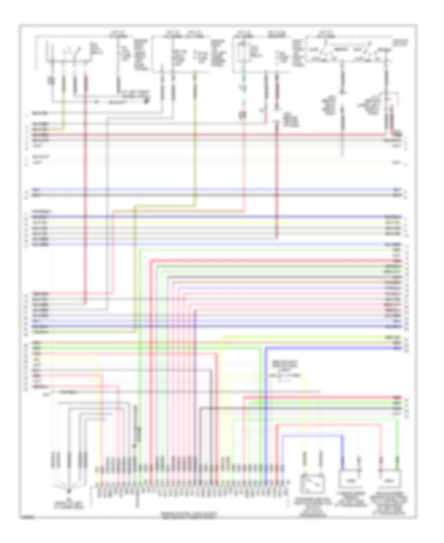
4.7L, Engine Performance Wiring Diagram (4 of 6) for Toyota Land Cruiser 2006
List of elements for 4.7L, Engine Performance Wiring Diagram (4 of 6) for Toyota Land Cruiser 2006:
- (behind right side of dash) j/c 27
- (engine harness, on trans) e8
- (left kick panel) cowl side j/b lh.
- 2nd strt ind
- A/t oil temp ind
- Air pump fuse 50a
- At/ p
- C12
- C13
- C15
- Combination meter
- Computer data lines system
- Cowl side jb rh. (right kick panel)
- Cpu
- D32
- E10
- Ect pwr ind
- Ed (at rear of left cylinder head)
- Electronically controlled transmission solenoid (on left side of transmission)
- Engine room r/b 8 (near front left susp tower)
- Hot at all times
- Hot in on or start
- J/c 17 (behind glove box)
- Knock sensor (bank 1) (on top left of engine block)
- Knock sensor (bank 2) (on top right of engine block)
- Met fuse 7.5a
- Mil ind
- Nca
- Ot+
- Ot-
- Ot2+
- Ot2-
- Q78
- Red
- Sl1+
- Sl1-
- Sl2+
- Sl2-
- Slt+
- Slt-
- Slu+
- Slu-
- Speedometer
- Tachometer
4.7L, Engine Performance Wiring Diagram (5 of 6) for Toyota Land Cruiser 2006
List of elements for 4.7L, Engine Performance Wiring Diagram (5 of 6) for Toyota Land Cruiser 2006:
- (engine harn, left side of engine) e11
- (on left side of transmission) (combination meter) vehicle speed sensor
- (top of left valve cover) ignition coil & igniter 1
- (top of left valve cover) ignition coil & igniter 3
- (top of left valve cover) ignition coil & igniter 5
- (top of left valve cover) ignition coil & igniter 7
- (top of right valve cover) ignition coil & igniter 2
- (top of right valve cover) ignition coil & igniter 4
- (top of right valve cover) ignition coil & igniter 6
- (top of right valve cover) ignition coil & igniter 8
- Aip
- Air pressure sensor (top center of engine)
- B11
- Bj (under driver's seat)
- Canister pressure sensor
- Canister pump module (center rear underside of vehicle)
- E10
- E11
- Ed (at rear of left cylinder head)
- Engine coolant temperature sensor (on top front of engine)
- Eo (front of left cylinder head)
- Gnd
- J/c 22 (above left rear wheelwell)
- Leak detection pump
- Noise filter (ignition)
- Output
- Red
- Sgnd
- Vcc
- Vent valve
- Vout
- Vsv (acis) (left rear of engine)
- Vsv (air swit- ching valve 1) (top right rear of engine)
- Vsv (air swit- ching valve 2) (top right rear of engine)
- Vsv (purge) (top left of engine)
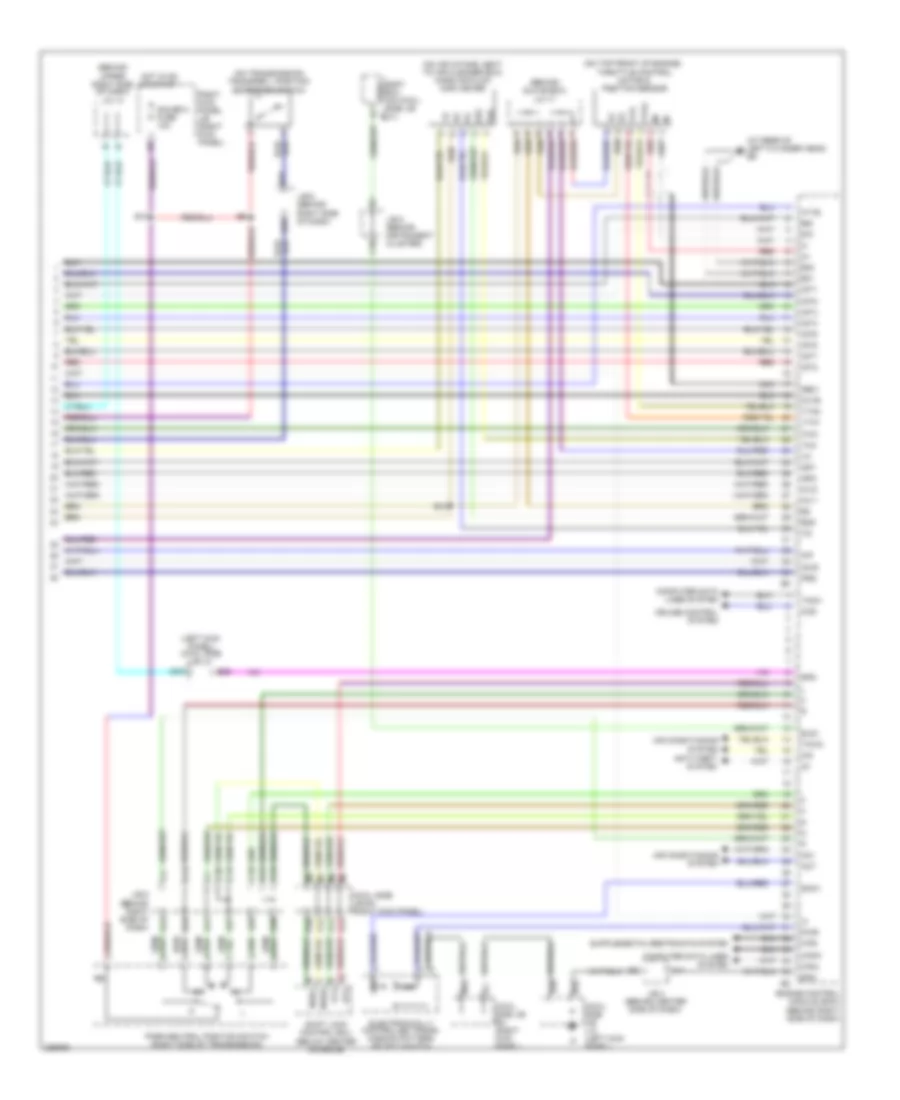
4.7L, Engine Performance Wiring Diagram (6 of 6) for Toyota Land Cruiser 2006
List of elements for 4.7L, Engine Performance Wiring Diagram (6 of 6) for Toyota Land Cruiser 2006:
- #70
- #80
- (at rear of left cylinder head) ed
- (behind glove box) j/c 17
- (behind upper right side of dash) j/c 14
- (left kick panel) cowl side j/b lh.
- (on air intake, next to air cleaner box) mass air flow (maf) meter
- (on top front of engine) throttle control motor & position sensor
- (on transmission) transfer l position detection switch
- 2nd
- Ac1
- Acis
- Act
- Aip
- Air conditioning system
- Aiv1
- Aiv2
- Anti-theft system
- At4
- Atl
- Body ecu (on cowl side j/b b7 lh.)
- C10
- C11
- C13
- C16
- C17
- C18
- C19
- C20
- Canh
- Canl
- Ccs
- Computer data lines system
- Cowl side j/b l/h. (left kick panel)
- Cowl side j/b rh. (right kick panel)
- Cruise control system
- D n
- D13
- D17
- D22
- D27
- D28
- D30
- D31
- D33
- D34
- E01
- E02
- E10
- E18
- E28
- E2g
- Electronically controlled trans- mission pattern select switch
- Els1
- Engine control module (ecm) (behind right side of dash)
- Eom
- F/ps
- Gauge 2 fuse 10a
- Ge01
- Hot in on or start
- Ht1b
- Igf1
- Igf2
- Igt1
- Igt2
- Igt3
- Igt4
- Igt5
- Igt6
- Igt7
- Igt8
- Imi
- Imo
- J/b 4 (behind center side of dash)
- J/b 5 (behind instrument cluster)
- J/b 6 (behind right side of dash)
- M10
- Nca
- Nssd
- Nssl
- Ox1b
- P10
- P12
- P13
- P14
- Park/neutral position switch (right side of transmission)
- Prg
- Pwr
- Q70
- Red
- Right kick panel j/b (right kick panel)
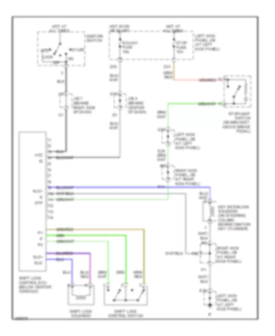
- Shift lock control ecu (below center console)
- Snwi
- Spd
- Tach
- Tha
- Thw
- Thwo
- Vta
- Vta1
- Vta2
EXTERIOR LIGHTS
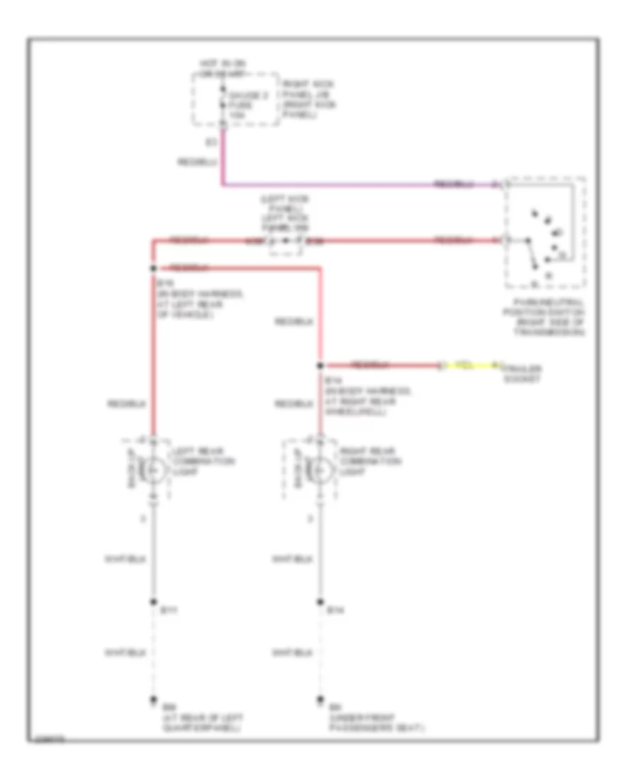
Back-up Lamps Wiring Diagram for Toyota Land Cruiser 2006
List of elements for Back-up Lamps Wiring Diagram for Toyota Land Cruiser 2006:
- (left kick panel) left kick panel j/b
- B11
- B14
- B14 (in body harness, at right rear wheelwell)
- B16 (in body harness, at left rear of vehicle)
- Bk (under front passenger's seat)
- Bm (at rear of left quarterpanel)
- E38
- Gauge 2 fuse 10a
- Hot in on or start
- K39
- Left rear combination light
- Light back-up
- Park/neutral position switch (right side of transmission)
- Right kick panel j/b (right kick panel)
- Right rear combination light
- Trailer socket
Exterior Lamps Wiring Diagram (1 of 2) for Toyota Land Cruiser 2006
List of elements for Exterior Lamps Wiring Diagram (1 of 2) for Toyota Land Cruiser 2006:
- (in body harness, in rear hatch) b15
- A37
- A47
- A49
- A58
- B11
- B11 (in body harness, at left rear wheelwell)
- B14
- B15
- B24
- B26
- B37
- B39
- B49
- B60
- B67
- Bj (under driver's seat)
- Bk (under front passenger's seat)
- Bm (at rear of left quarterpanel)
- Body ecu (on left kick panel j/b)
- C16
- Combination switch
- E35
- Ea (at front of right front fender)
- Ee (at left front fender apron)
- Engine room j/b (on left inner fender panel)
- F15
- Fusible link block (on left side of engine compt, near battery)
- Head
- Hot at all times
- Idl
- J/b 1 fuse 120a
- J/b 5 (behind instrument cluster)
- Left front side marker, parking & turn signal light
- Left kick panel j/b (left kick panel)
- Left license plate light
- Light control switch
- Off tail
- Parking
- R12
- R13
- Right front side marker, parking & turn signal light
- Right kick panel j/b (right kick panel)
- Right license plate light
- Right rear combination light
- Side marker
- Stop/ tail
- Tail
- Tail fuse 15a
- Tail relay
- Trly
- Turn
Exterior Lamps Wiring Diagram (2 of 2) for Toyota Land Cruiser 2006
List of elements for Exterior Lamps Wiring Diagram (2 of 2) for Toyota Land Cruiser 2006:
- (in body harness, at left rear wheelwell) b11
- (in body harness, behind right rear wheelwell)
- A/c control assembly (w/o navigation system)
- A12
- A13
- A45
- A47
- B11
- B15
- B25
- B26
- B65
- Bj (under driver's seat)
- Bm (at rear of left quarterpanel)
- C11
- C12
- C15
- Center cluster integration panel (w/ navigation system)
- Combination meter
- Combination switch
- D25
- D31
- D35
- E18
- E26
- E31
- E32
- E35
- E36
- Ecu-ig2 fuse 10a
- Ed (at rear of left cylinder head)
- Ehw
- Engine room j/b (on left inner fender panel)
- Gnd
- Haz- trn fuse 15a
- High mounted stop light
- Hot at all times
- Hot in on or start
- Hzd
- Hzr
- J/b 6 (behind right side of dash)
- Junction connector 11 (behind upper center of dash)
- Junction connector 3 (behind upper left side of dash)
- K35
- K40
- Left
- Left kick panel j/b (left kick panel)
- Left rear combination light
- M14
- Q39
- R10
- R11
- Right
- Right kick panel j/b (right kick panel)
- Stop
- Stop fuse 15a
- Stop/ tail
- Stoplight switch (on bracket, above brake pedal)
- Tail
- Towing brake controller (left side of dash)
- Towing converter relay (on left rear of cargo area)
- Turn
- Turn signal flasher (behind left side of dash)
- Turn signal indicator lights
- Turn signal switch
Trailer Tow Wiring Diagram for Toyota Land Cruiser 2006
List of elements for Trailer Tow Wiring Diagram for Toyota Land Cruiser 2006:
- (left kick panel)
- (on bracket, above brake
- (right kick panel) right kick panel j/b
- (under
- A12
- A16
- B16
- B58
- B61
- B69
- B72
- Batt charge fuse 30a
- Bk (under front passenger's seat)
- Brk
- C11
- D31
- D35
- Driver's seat) bj
- E26
- E31
- E34
- E38
- Ecu-ig1 fuse 10a
- Engine room j/b (on left inner fender panel)
- Gauge 2 fuse 10a
- Gnd
- Hot at all times
- Hot in on or start
- J/b 6 (behind right side of dash)
- J/c 22 (above left rear wheelwell)
- K23
- K35
- K39
- K40
- Left kick panel j/b
- Left kick panel j/b (left kick panel)
- M14
- Park/neutral position switch (right side of transmission)
- Pedal)
- Red
- Right kick panel j/b (right kick panel)
- Stop
- Stop fuse 15a
- Stoplight
- Switch
- Tail
- Tail fuse 15a
- Towing brake controller (left side of dash)
- Towing brake fuse 30a
- Towing converter relay (on left rear of cargo area)
- Towing fuse 30a
- Towing hitch relay (left rear of vehicle cargo area)
- Towing tail fuse 30a
- Trailer socket
- Turn signal flasher (behind left side of dash)
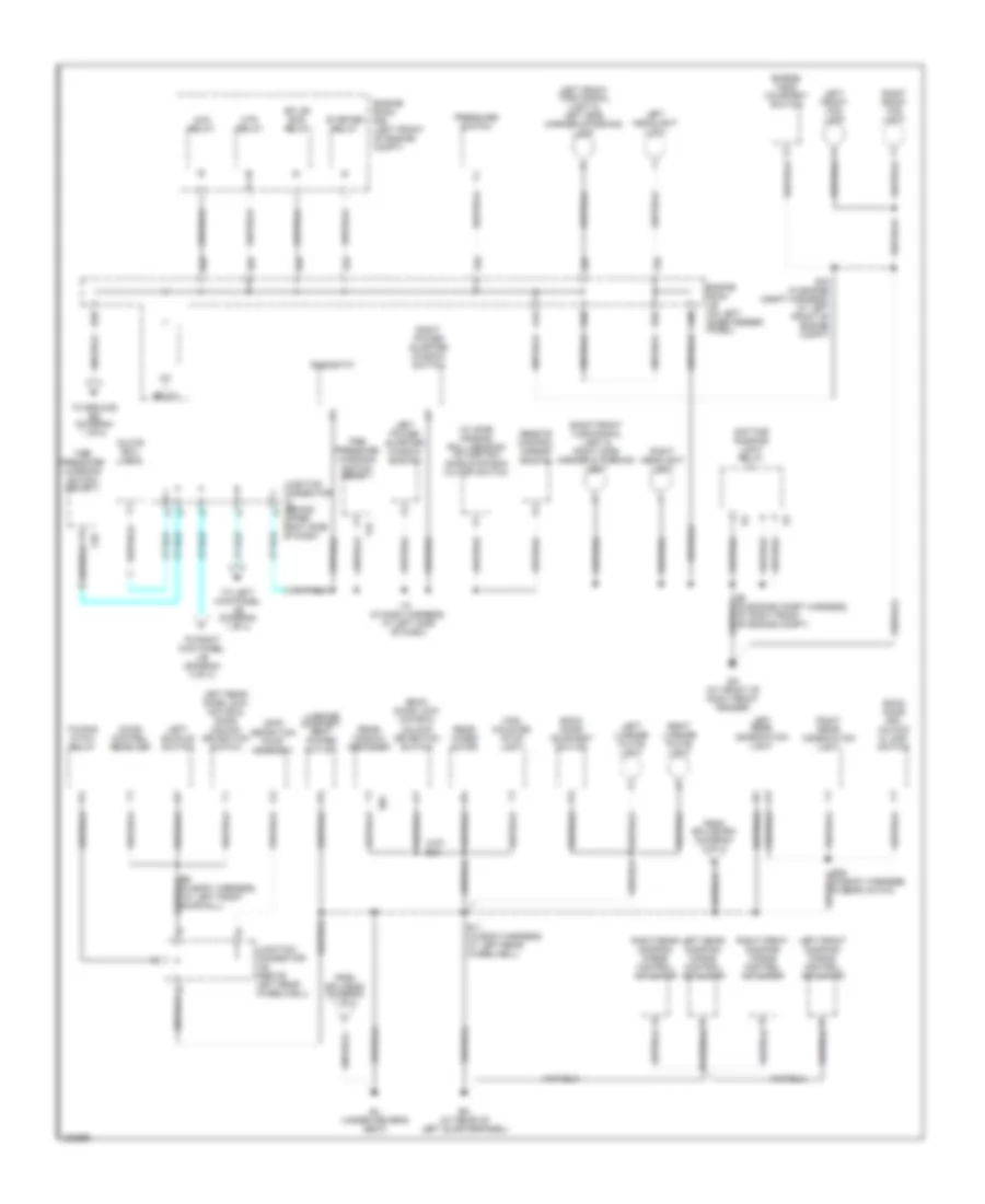
GROUND DISTRIBUTION
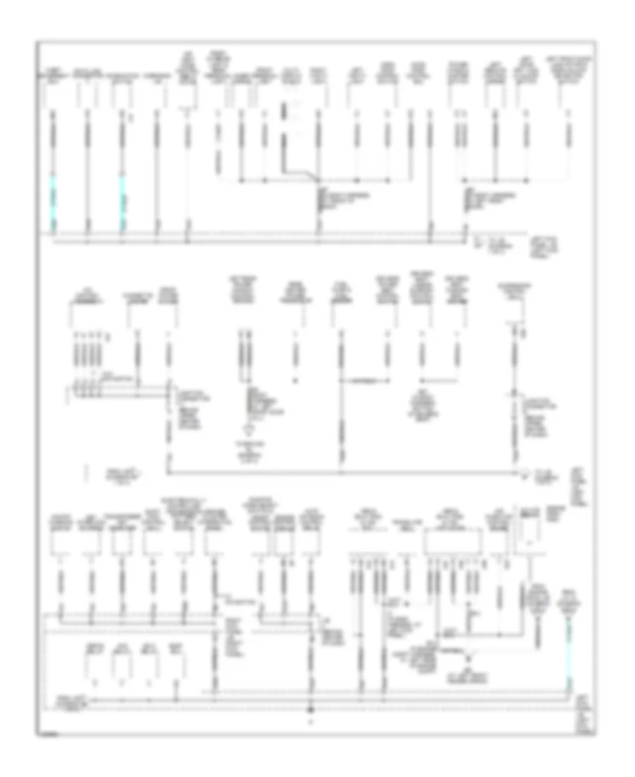
Ground Distribution Wiring Diagram (1 of 4) for Toyota Land Cruiser 2006
List of elements for Ground Distribution Wiring Diagram (1 of 4) for Toyota Land Cruiser 2006:
- 1 of 4)
- A/c control assembly
- A/f htr relay
- A37
- A38
- A40
- A41
- A42
- A47
- A53
- Abs & ba & trac & vsc actuator
- Abs & ba & trac & vsc ecu
- Acc relay
- Air injection control driver
- Air vent mode control servo motor
- Auto antenna control relay
- B13
- B2 (in body harness, in left front door)
- B27 (in body harness, bottom of driver's seat)
- B4 (body harness, at left front door sill)
- B7 (in body harness, at front of roof)
- Body ecu
- C11
- C17
- Center cluster integration panel
- Cigarette lighter
- Combination switch
- D18
- D22
- D23
- Damping mode select switch & height control switch
- Data link connector
- Defog relay
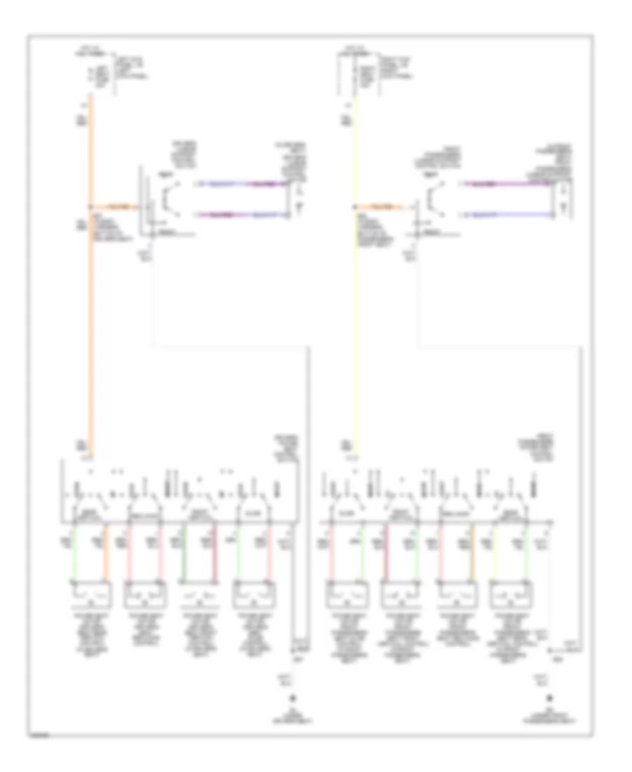
- Driver's power seat control switch
- Driver's seat cushion seat heater
- Driver's seat lumbar support control switch
- E14
- E14 (in engine compt harness, at left rear of engine compt)
- E18
- E34
- Ee (at left front fender apron)
- Electronically controlled transmission pattern select switch
- Engine control module
- Engine room r/b 8
- From engine room j/b (diagram 2 of 4)
- From j/b (diagram 1 of 4)
- From j/b (diagram b
- From j/c 12 (diagram 2 of 4)
- Front interior light & rear personal light
- Front personal light
- Front power outlet
- Fuel pump & fuel sender
- I2 (in dash harness, at left kick panel)
- Ign 2 relay
- Inner mirror
- J/b (behind center of dash)
- Junction connector (behind upper center of dash)
- K33
- Key interlock solenoid
- L11
- L14
- Left door key lock & unlock switch
- Left front door lock motor & door unlock detection switch
- Left kick panel j/b (left kick panel)
- Left rear power window control switch
- Left remote control mirror
- Left vanity light
- M10
- Moon roof control ecu
- Moon roof control switch
- Multi- display shield
- Nca
- Overhead j/b
- Power window master switch
- Q20
- Q23
- Q43
- Rear heater power transistor
- Right kick panel j/b (right kick panel)
- Right vanity light
- S20
- Shift lock control ecu
- Suspension control ecu
- Theft deterrent ecu
- To ground bj (diagram 2 of 4)
- To j/b (diagram 1 of 4)
- To j/b (diagram 1 of 4)
- Translate ecu
- Transponder key computer
- Unlock warning switch
- W/ navigation
- W/o navigation
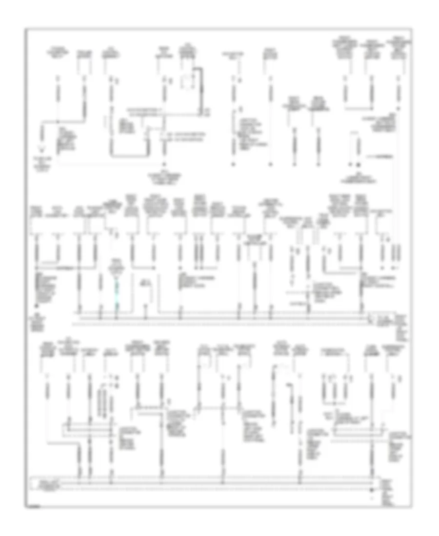
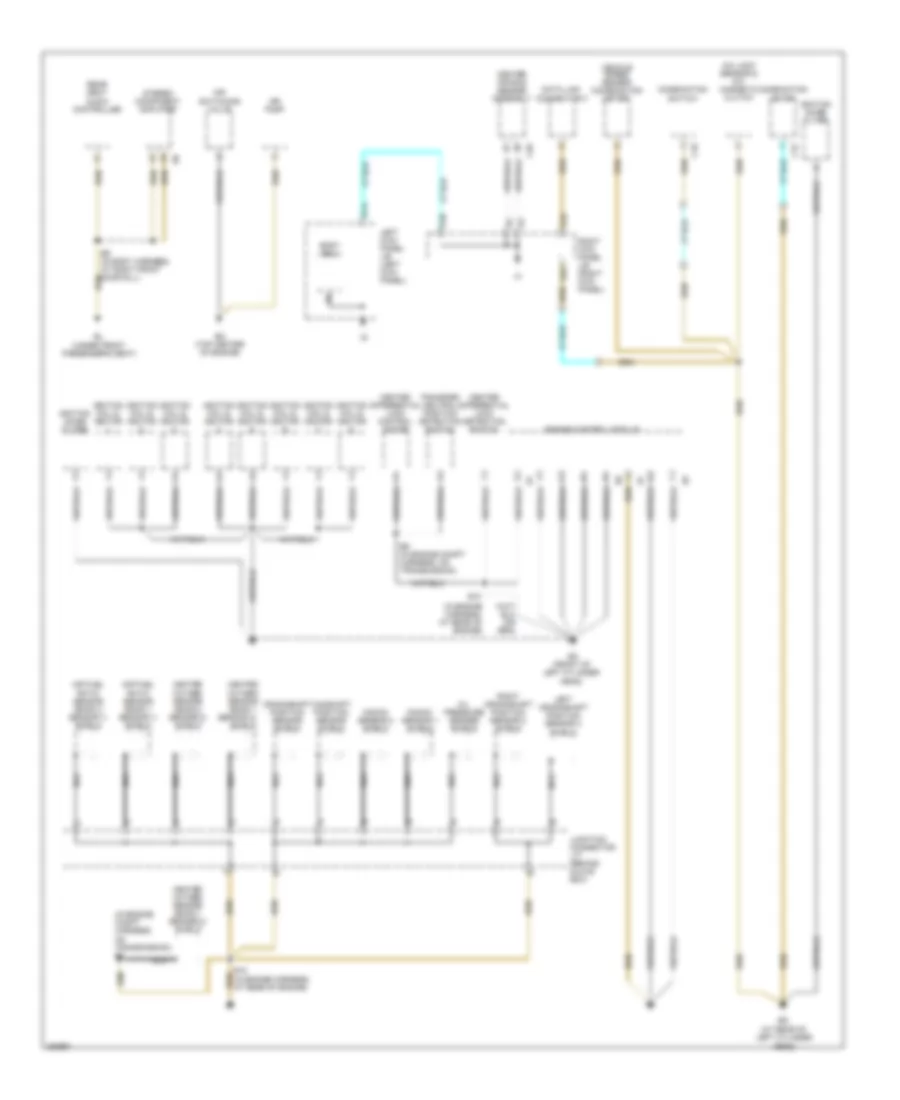
Ground Distribution Wiring Diagram (2 of 4) for Toyota Land Cruiser 2006
List of elements for Ground Distribution Wiring Diagram (2 of 4) for Toyota Land Cruiser 2006:
- (w/ side air bag) roll sensing of curtain shield air bag cutoff switch
- A24
- A30
- A34
- A37
- A43
- Ahc relay
- B11 (in body harness, at left rear wheelwell)
- B26 (in body harness, in rear hatch)
- B35
- B39
- B40
- B42
- B43
- B44
- B56
- B6 (in body harness, (at left front door sill)
- Back door courtesy switch
- Back door key unlock & lock switch
- Back door lock motor & unlock detection switch
- Bj (under driver's seat)
- Bm (at rear of left quarterpanel)
- Daytime running light relay
- Door control receiver
- E15 (in engine compt harness, at left front of engine compt)
- E2 (in engine compt harness, at right front of engine compt)
- Ea (at front of right front fender)
- Efi or ecd relay
- Engine hood courtesy switch
- Engine room j/b (on left inner fender panel)
- Engine room r/b (left front of engine compt)
- From splice b16 (diagram 3 of 4)
- From splice b4 (diagram 1 of 4)
- Glove box light
- High mounted stop light
- Htr relay
- I18 (in dash harness, at left side of dash)
- Ig1 relay
- Junction connector (behind upper right side of dash)
- Junction connector j22 (above left rear wheelwell)
- Leak detection pump assembly
- Left buckle switch
- Left front damping force control actuator
- Left front fog light
- Left front turn signal light & left side marker & parking light
- Left headlight (low)
- Left license plate light
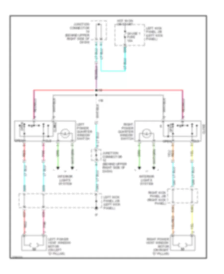
- Left power quarter window switch
- Left rear combination light
- Left rear damping force control actuator
- Left rear door lock motor & door unlock detection switch
- Luggage compart- ment power outlet
- Pressure switch
- R29
- Rear window defogger
- Rear wiper motor
- Remote control mirror switch
- Rheostat
- Right front damping force control actuator
- Right front fog light
- Right front turn signal light & right side marker & parking light
- Right headlight (low)
- Right license plate light
- Right power quarter window switch
- Right rear combination light
- Right rear damping force control actuator
- Starter relay
- T27
- T28
- Tire pressure warning switch (reset)
- Tire pressure warning switch (select)
- To ground ee (diagram 1 of 4)
- To left kick panel j/b (diagram 1 of 4)
- To right kick panel j/b (diagram 3 of 4)
- Towing hitch relay
Ground Distribution Wiring Diagram (3 of 4) for Toyota Land Cruiser 2006
List of elements for Ground Distribution Wiring Diagram (3 of 4) for Toyota Land Cruiser 2006:
- (behind upper center of dash)
- (w/ navigation)
- (w/ navigation) dvd automatic changer
- (w/o navigation)
- 3 of 4)
- A/c control assembly
- A/c control assembly shields
- A32
- A47
- Ahc main relay
- Ahc pump motor
- Auto antenna motor
- Auto antenna motor shields
- B14 (in body harness, at right rear wheelwell)
- B28 (in body harness, bottom of passenger's front seat)
- B8 (in body harness, in right front door)
- B9 (in body harness, at right front door sill)
- Bk (under front passenger's seat)
- Blower motor controller
- C16
- C19
- Center differential lock control relay
- Combination switch
- D10
- D18
- D23
- D42
- Data link connector 1
- Driver's seat heater switch
- E34
- E35
- E5 (in engine compt harness, at right front of engine compt)
- Eb (at right front fender apron)
- F (w/o navigation)
- F j23
- F10
- From j/b (diagram h
- From j/c 12 (diagram 2 of 4)
- Front passenger's power seat control switch
- Front passenger's seat cushion heater
- Front passenger's seat heater switch
- Front passenger's seat lumbar support control switch
- Front wiper motor
- Gateway ecu
- H (w/ navigation)
- H j25
- I9 (in dash harness, at left side of dash)
- Ig1 3 relay
- J/b (right kick panel)
- J/b 4 (behind center of dash)
- J19
- J23 f
- J25
- Junction connector (behind center of dash)
- Junction connector 8
- Junction connector j1 (behind
- Junction connector j16 (behind upper right side of dash)
- Junction connector j18 & j19 (under j18 front of center console)
- Junction connector j23 & j25 (j23: in back j25 door) (j25: right rear of cargo area)
- Junction connector j3 (behind upper left side of dash)
- K31
- Left side of dash, near left kick panel)
- Multi- display
- Navigation ecu
- Nca
- Q58
- Rear a/c amplifier
- Rear console power outlet
- Rear cooler power transistor
- Rear of vehicle)
- Right buckle switch
- Right door key lock & unlock switch
- Right door lock control switch
- Right front door lock motor & door unlock detection switch
- Right front power window control switch
- Right kick panel
- Right kick panel j/b (right kick panel)
- Right rear combination light
- Right rear door lock motor & door unlock detection switch
- Right rear power window control switch
- Right remote control mirror
- Running light resistor
- S20
- S22
- Suspension control ecu
- T22
- T25
- Tele- vision camera ecu
- Telescopic motor shield
- Tilt motor shield
- Tilt & telescopic ecu
- Tire pressure monitor ecu
- To j/b (diagram 3 of 4)
- To splice b11 (diagram 2 of 4)
- Towing brake controller
- Towing converter relay
- Trailer socket
- Turn signal flasher
- W/ navigation
- W/o navigation
Ground Distribution Wiring Diagram (4 of 4) for Toyota Land Cruiser 2006
List of elements for Ground Distribution Wiring Diagram (4 of 4) for Toyota Land Cruiser 2006:
- (at rear of left cylinder head)
- (in engine compt harness, on transmission) e8
- (in engine harness, at rear of engine)
- A/c lock sensor & a/c magnetic clutch
- Air fuel ratio sensor (bank 1 sensor 1) shield
- Air fuel ratio sensor (bank 2 sensor 1) shield
- Air pump
- Air switching valve
- B9 (in body harness, at right front door sill)
- Bl (under front passenger's seat)
- Body ecu
- C15
- C18
- C26
- Camshaft position sensor shield
- Center air bag sensor assembly
- Center differential lock control motor
- Center differential lock detection switch
- Combination meter
- Combination switch
- Crankshaft position sensor shield
- Data link connector 3
- E10
- E10 (in engine harness, at rear of engine)
- E9 (in engine compt harness, on transmission)
- En (top center of engine)
- Engine control module
- Eo (front of left cylinder head)
- Heated oxygen sensor (bank 1
- Heated oxygen sensor (bank 1 sensor 2) shield
- Heated oxygen sensor (bank 2 sensor 2) shield
- Ignition coil & ignitor
- Ignition noise filter
- Junction connector j17 (behind glove box)
- Knock sensor 1 shield
- Knock sensor 2 shield
- Left crankshaft position sensor 2 shield
- Left kick panel j/b (left kick panel)
- Nca
- Oil pressure sender shield
- Q14
- Q40
- Rear seat audio controller
- Right crankshaft position sensor 2 shield
- Right kick panel j/b (right kick panel)
- Sensor 2)
- Shield
- Stereo component amplifier
- Transfer neutral position detection switch
- Vehicle speed sensor (combination meter)
HEADLIGHTS
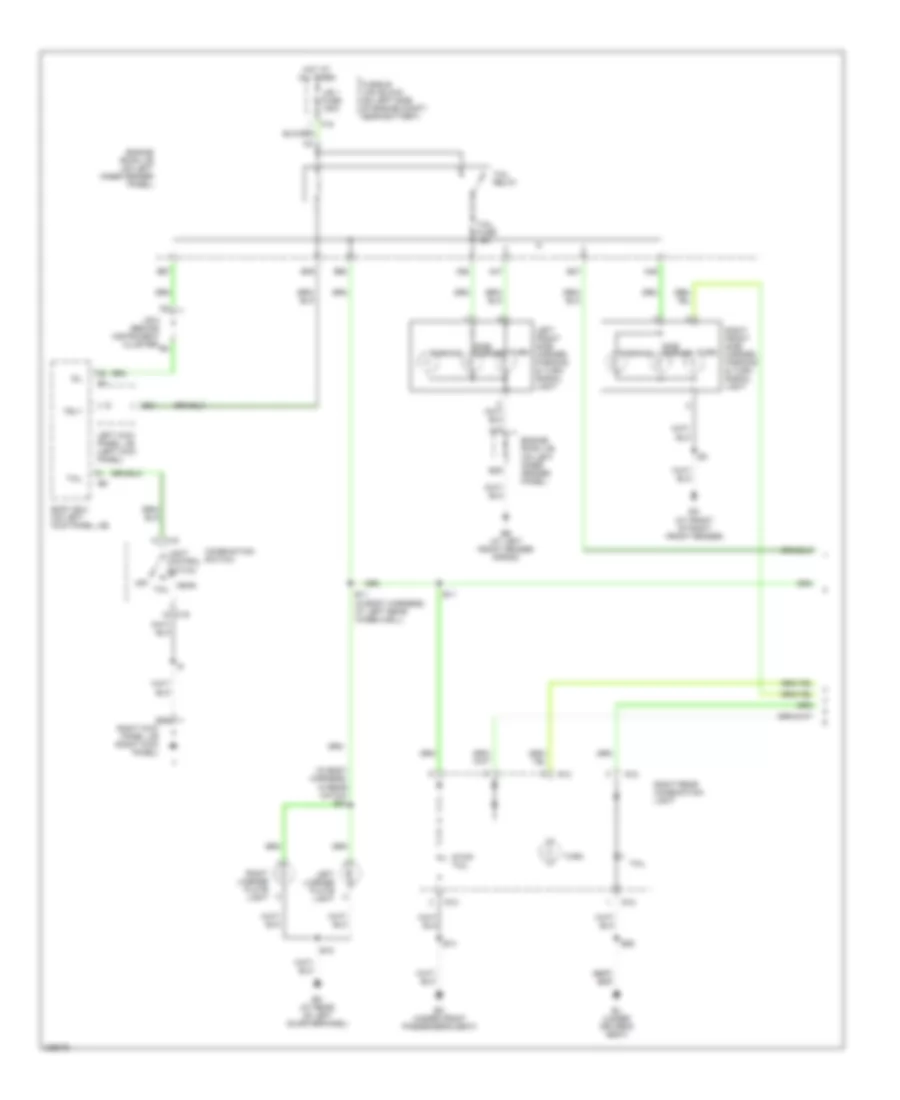
Headlights Wiring Diagram (1 of 2) for Toyota Land Cruiser 2006
List of elements for Headlights Wiring Diagram (1 of 2) for Toyota Land Cruiser 2006:
- A16
- A40
- A61
- A62
- A64
- Acc
- Acc fuse 7.5a
- Auto
- Automatic light control sensor (on top right side of dash)
- B24
- B38
- B59
- Bdr1
- Becu
- Body ecu
- Cltb
- Clte
- Clts
- Combination switch
- Dcty
- Dimmer switch
- Door fuse 25a
- Drl
- E11
- E15
- E18
- E23
- E35
- Ea (at front of right front fender)
- Ecu-ig1 fuse 10a
- Engine room j/b (on left inner fender panel)
- Exterior lights system
- Flash
- Fog light switch
- Fr fog fuse 15a
- Fr fog relay
- Generator
- Gnd1
- Gnd2
- Head
- Hf2
- High
- Hot at all times
- Hot in on or acc
- Hot in on or start
- Hrly
- If (at left kick panel j/b)
- Ig (at left kick panel j/b)
- Interior lights system
- Junction connector (behind center of dash)
- Junction connector 28 (behind center of dash)
- Junction connector 6 (behind upper left side of dash)
- K10
- Ksw
- Left front door courtesy switch
- Left front fog light
- Left kick panel j/b (left kick panel)
- Light control switch
- Low
- Off
- Pkb
- Q22
- Q53
- Red
- Right front fog light
- Right kick panel j/b (right kick panel)
- Sig
- Tail
- Trly
- Unlock warning switch (left side of dash)
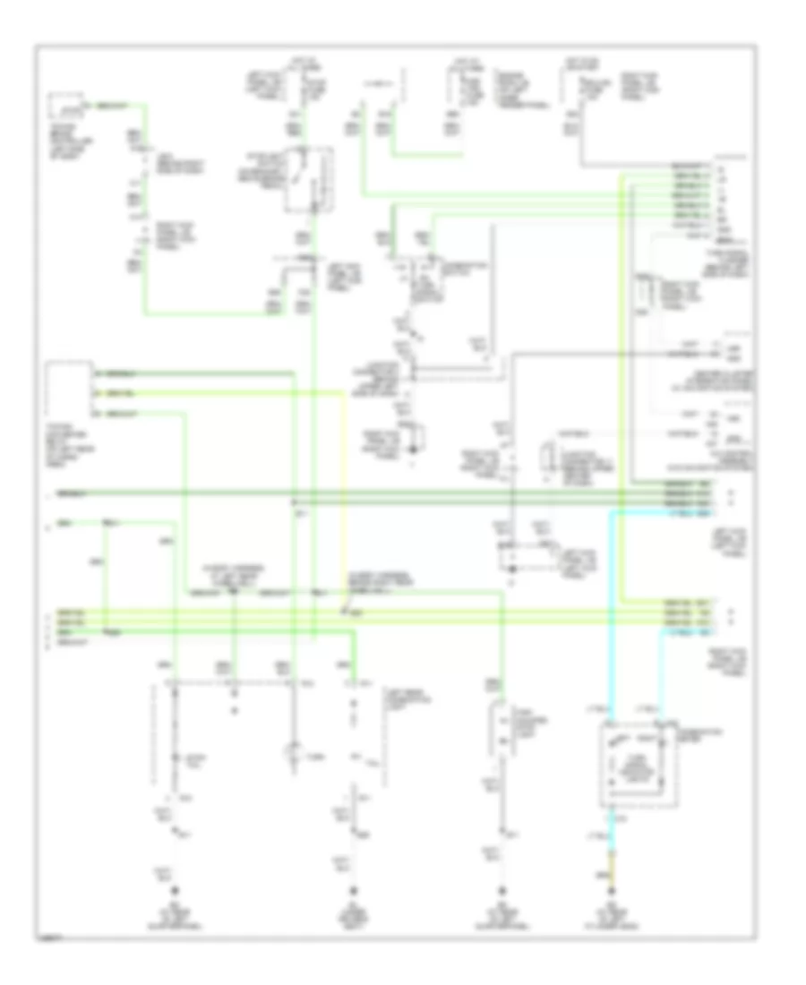
Headlights Wiring Diagram (2 of 2) for Toyota Land Cruiser 2006
List of elements for Headlights Wiring Diagram (2 of 2) for Toyota Land Cruiser 2006:
- (at front of right front fender) ea
- (right kick panel)
- A12
- A19
- A20
- A22
- A24
- A26
- A30
- B10
- B13
- B22
- C12
- C14
- Combination meter
- Daytime running light relay 3 (on right front inner fender panel)
- E1 (in engine compt harness, at right front of engine compt)
- E14
- Ea (at front of right front fender)
- Ecu-b2 fuse 10a
- Engine room j/b (on left inner fender panel)
- Head hi relay
- Head relay
- High beam indicator
- Hot at all times
- Junction connector 13 (behind upper right side of dash)
- K27
- Left high headlight
- Left kick panel j/b (left kick panel)
- Left low headlight
- Left lower head fuse 10a
- Left upper head fuse 20a
- Parking brake switch (on base of park brake lever)
- Q31
- Q37
- Q71
- Right high headlight
- Right kick panel j/b
- Right kick panel j/b (right kick panel)
- Right low headlight
- Right lower head fuse 10a
- Right upper head fuse 20a
- Running light resistor (right side of engine compartment)
HORN
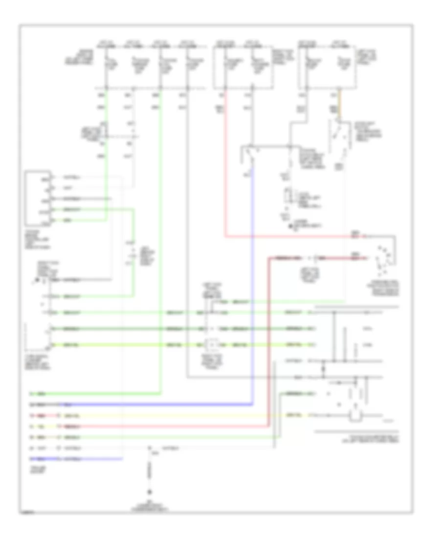
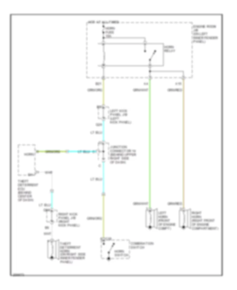
Horn Wiring Diagram for Toyota Land Cruiser 2006
List of elements for Horn Wiring Diagram for Toyota Land Cruiser 2006:
- A15
- B21
- C18
- Combination switch
- Engine room j/b (on left inner fender panel)
- Horn
- Horn fuse 10a
- Horn relay
- Horn switch
- Hot at all times
- Junction connector 14 (behind upper right side of dash)
- Left horn (front of engine compt)
- Left kick panel j/b (left kick panel)
- Q24
- Q84
- Right horn (right front of engine compartment)
- Right kick panel j/b (right kick panel)
- Sh-
- Theft deterrent ecu (behind center of dash)
- Theft deterrent horn (on right side inner fender panel)
INSTRUMENT CLUSTER
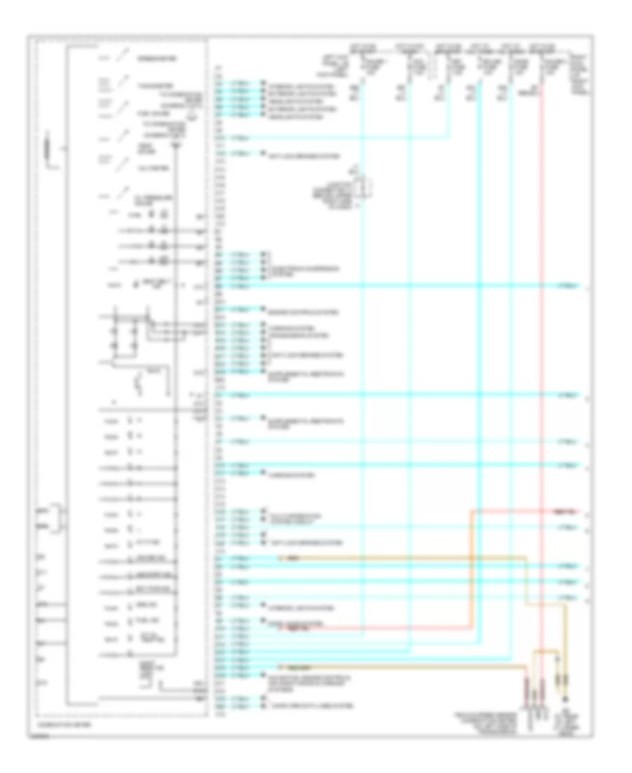
Instrument Cluster Wiring Diagram (1 of 2) for Toyota Land Cruiser 2006
List of elements for Instrument Cluster Wiring Diagram (1 of 2) for Toyota Land Cruiser 2006:
- 2nd strt ind
- A/t oil temp ind
- A/t p ind
- A10
- A11
- A12
- A13
- A14
- A15
- A16
- A17
- A18
- A19
- A20
- Acc fuse 7.5a
- Anti-lock brakes system
- B10
- B11
- B12
- B13
- B14
- B15
- B16
- B17
- B18
- B19
- B20
- Buzzer
- C10
- C11
- C12
- C13
- C14
- C15
- C16
- C17
- C18
- C19
- C20
- Combination meter
- Computer data lines system
- Cruise ind
- D10
- D11
- D12
- D13
- D14
- D15
- D16
- D17
- D18
- D19
- D20
- Dome fuse 10a
- Door locks system
- Ect pwr ind
- Ecu-b2 fuse 10a
- Ed (at rear of left cylinder head)
- Electronic suspension system
- Engine controls system
- Exterior lights system
- Fuel gauge
- Fuel ind
- Gauge 1 fuse 10a
- Gauge 2 fuse 10a
- Headlights system
- Hi ind
- Hot at all times
- Hot in acc or on
- Hot in on or start
- Interior lights system
- Junction connector 14 (behind upper right side of dash)
- Left kick panel j/b (left kick panel)
- Lo ind
- Maint reqd ind (usa)
- Met fuse 7.5a
- Multi-information system circuit
- N ind
- Navigation, engine controls, air conditioning & warning systems
- Off ind
- Oil pressure gauge
- Right kick panel j/b (right kick panel)
- Seat belt ind
- Speedometer
- Srs ind
- Tachometer
- Temp gauge
- To combination meter (diagram 2 of 2)
- Transmission system
- Vehicle speed sensor (combination meter) (on left side of transmission)
- Voltmeter
- Warning system
Instrument Cluster Wiring Diagram (2 of 2) for Toyota Land Cruiser 2006
List of elements for Instrument Cluster Wiring Diagram (2 of 2) for Toyota Land Cruiser 2006:
- (except usa built)
- (usa built)
- A12
- Abs ind
- Active trc ind (except usa built)
- B11
- B13
- B14
- B15
- B16
- B17
- B18
- B19
- B63
- Back door courtesy switch (right rear of cargo area)
- Bcty
- Beam ind
- Bj (under driver's seat)
- Body ecu (on left kick panel j/b)
- Brake ind (except usa built)
- Brake ind (usa built)
- C14
- C18
- C19
- C20
- Center diff lock ind
- Charge ind
- Combination meter
- Computer data lines system
- D14
- Data link connector 3 (behind left side of dash, right of steering column)
- Dcty
- Dcy2
- Door ind
- E13
- E14
- E15
- Ed (at rear of left cylinder head)
- Engine room j/b (on left inner fender panel)
- From combination meter (diagram 1 of 2)
- Fuel pump & sender (in fuel tank)
- Heat wire
- Hot w/ tail relay energized
- J/b 4 (behind center of dash)
- Junction connector (behind glove box)
- Junction connector 12 (behind upper right side of dash)
- Junction connector 22 (above left rear wheelwell)
- K10
- K13
- K19
- K21
- K26
- K27
- Left front door courtesy switch
- Left kick panel j/b (left kick panel)
- Left rear door courtesy switch
- Left turn ind
- Malfunction indicator lamp
- Mpx5
- Mpx6
- Nca
- Oil pressure sender (on lower left front side of engine)
- Panel fuse 7.5a
- Parking brake switch (on base of park brake lever)
- Pcty
- Pkb
- Q14
- Q31
- Q37
- Q61
- Q62
- Q63
- Q83
- Right front door courtesy switch
- Right kick panel j/b (right kick panel)
- Right rear door courtesy switch
- Right turn ind
- Rlcy
- Rrcy
- Rsca off ind
- Slip ind
- Tac
- Tire pressure ind
- Trac ind (usa built)
- Vsc off ind
- Vsc trac ind
- Vsc trc ind
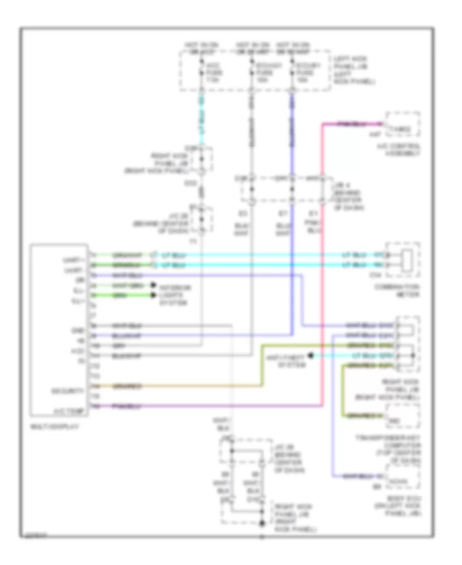
Multi-Information System Wiring Diagram for Toyota Land Cruiser 2006
List of elements for Multi-Information System Wiring Diagram for Toyota Land Cruiser 2006:
- A/c control assembly
- A/c temp
- A15
- A47
- Acan
- Acc
- Acc fuse 7.5a
- Anti-theft system
- Body ecu (on left kick panel j/b)
- C14
- Combination meter
- D10
- D11
- D12
- D13
- D16
- D21
- D33
- E21
- E27
- Ecu-b1 fuse 10a
- Ecu-ig1 fuse 10a
- Gnd
- Hot in on or acc
- Hot in on or start
- Ill+
- Ill-
- Ind
- Interior lights system
- J/b 4 (behind center of dash)
- J/c 28 (behind center of dash)
- Left kick panel j/b (left kick panel)
- Multi-display
- Q18
- Q76
- Right kick panel j/b (right kick panel)
- Security
- Tamo2
- Transponder key computer (top center of dash)
- Uart+
- Uart-
INTERIOR LIGHTS
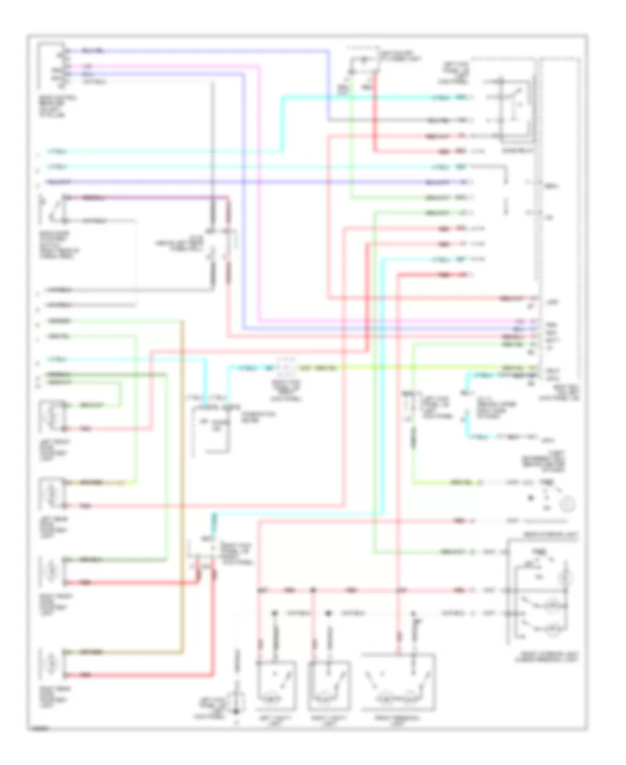
Courtesy Lamps Wiring Diagram (1 of 2) for Toyota Land Cruiser 2006
List of elements for Courtesy Lamps Wiring Diagram (1 of 2) for Toyota Land Cruiser 2006:
- Acc
- Acc fuse 7.5a
- B11
- B2 (in body harness, in left front door)
- Back door key lock & unlock switch
- Bdr
- Bdr1
- Bj (under driver's seat)
- Body ecu (on left kick panel j/b)
- Cpub
- Dcty
- Dcyl
- Dome fuse 10a
- Door fuse 25a
- E15
- E40
- E42
- Ecu-b2 fuse 10a
- Ecu-ig1 fuse 10a
- Gnd
- Gnd1
- Gnd2
- Hot at all times
- Hot in acc or on
- Hot in on or start
- If (at left kick panel j/b)
- Ig (at left kick panel j/b)
- J13
- J14
- K10
- K24 k24
- K26
- K29
- Keye
- Kul
- Lcyl
- Left door key lock & unlock switch
- Left front door courtesy switch
- Left kick panel j/b (left kick panel)
- Left rear door courtesy switch
- Mpx1
- P/w (fl) fuse 20a
- Pcty
- Pcyl
- Power window master switch
- Q10
- Q11
- Q12
- Q17
- Q30
- Q35
- Q41
- Q42
- Q45
- Q71
- Rcyl
- Right door key lock & unlock switch
- Right door lock control switch
- Right front door courtesy switch
- Right kick panel j/b (right kick panel)
- Right rear door courtesy switch
- Rlcy
- Rrcy
- Sig
- Ul1
- Ul2
Courtesy Lamps Wiring Diagram (2 of 2) for Toyota Land Cruiser 2006
List of elements for Courtesy Lamps Wiring Diagram (2 of 2) for Toyota Land Cruiser 2006:
- Back door courtesy switch (right rear of cargo area)
- Bcty
- Becu
- Body ecu (on left kick panel j/b)
- C12
- C15
- Combination meter
- Dome relay
- Door
- Door control receiver (on left "d" pillar)
- Door ind
- Drlp
- E12
- E15
- E19
- E22
- Front interior light & rear personal light
- Front personal light
- Ignition key cylinder light
- Ile
- J/c 14 (behind upper right side of dash)
- J/c 22 (above left rear wheelwell)
- K22
- L11
- L18
- Left front door courtesy light
- Left kick panel j/b (left kick panel)
- Left rear door courtesy light
- Left vanity light
- Lmry
- Mpx1
- Mpx3
- Off
- Prg
- Q22
- Q27
- Q79
- Rda
- Rear interior light
- Red
- Right front door courtesy light
- Right kick panel j/b (right kick panel)
- Right rear door courtesy light
- Right vanity light
- Theft deterrent ecu (behind center of dash)
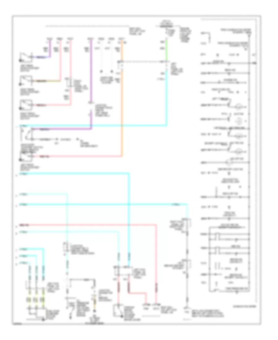
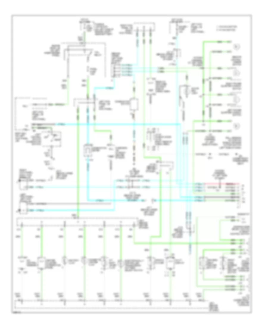
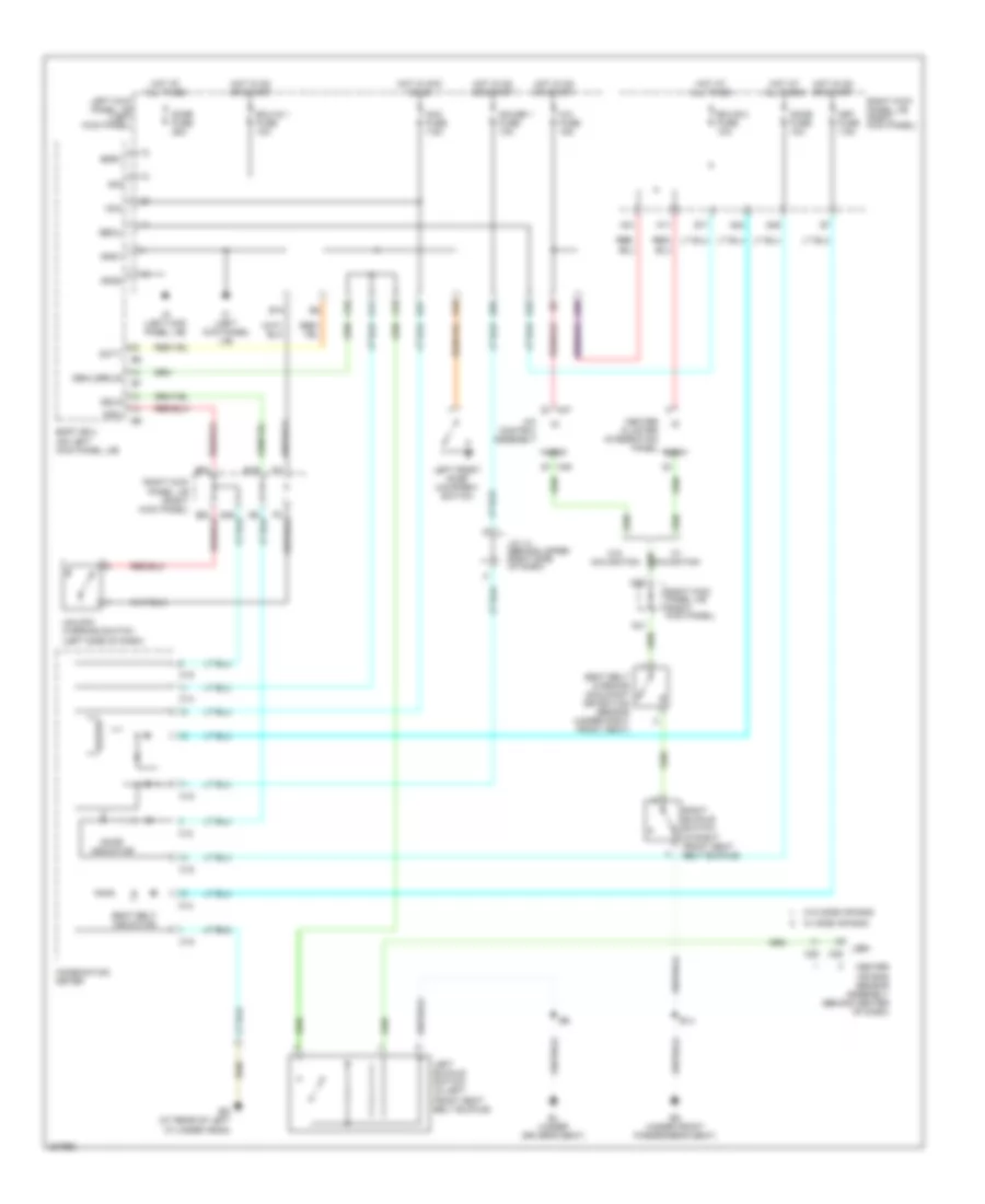
Instrument Illumination Wiring Diagram for Toyota Land Cruiser 2006
List of elements for Instrument Illumination Wiring Diagram for Toyota Land Cruiser 2006:
- (behind upper left side of dash) j/c 7
- (in dash harness, at left side of dash)
- (left kick panel) left kick panel j/b
- (right kick panel) right kick panel j/b
- A/c control assembly
- A/t shift lever illum
- A11
- A13
- A14
- A32
- A47
- Ashtray illum
- B11
- B14
- B24
- B49
- B63
- Bk (under front passenger's seat)
- Body ecu (on left kick panel j/b)
- C13
- C14
- C15
- Center cluster integration panel
- Cigarette lighter illum
- Combination meter
- Combination switch
- D13
- D15
- D16
- D35
- Damping mode select switch & height control switch
- Driver's seat heater switch
- E35
- Ed (at rear of left cylinder head)
- Electronically controlled transmission pattern select switch
- Engine room j/b (on left inner fender panel)
- Front pass- enger's seat heater switch
- Fusible link block (on left side of engine compt, near battery)
- Gauge 1 fuse 10a
- Gill
- Glove box light
- Gnd
- Head
- Hot at all times
- Hot in on or start
- I18
- I19
- I19 (in dash harness, at left side of dash)
- Ill+
- Ill+1
- Ill-
- J/b 1 fuse 120a
- J/b 4 (behind center of dash)
- J/c 12 (behind upper right side of dash)
- J/c 14 (behind upper right side of dash)
- J/c 18 & 19 (under front of center console)
- J/c 20 & 21 (under front of center console)
- J/c 23 (in back door) j/c 25 (right rear of cargo area)
- J/c 28 (behind center of dash)
- J/c 3 (behind upper left side of dash)
- J/c 6 (behind upper left side of dash)
- J/c 7 (behind upper left side of dash)
- J18
- J19
- J20
- J21
- J23
- J25
- K20
- L14
- Left kick panel j/b (left kick panel)
- Left power quarter window switch
- Light control switch (combination switch)
- Multi- display
- Off
- Overhead j/b (in front center of roof)
- Panel fuse 7.5a
- Q43
- Q55
- Q58
- Q65
- Q68
- Q83
- Radio & player
- Rear a/c amplifier (on right side of cargo area)
- Remote control mirror switch
- Rheostat
- Right kick panel j/b (right kick panel)
- Right power quarter window switch
- Roll sensing of curtain shield air bags cutoff switch (left side of dash)
- Tail
- Tail relay
- Trly
- W/ navigation
- W/o navigation
NAVIGATION
Navigation Wiring Diagram (1 of 2) for Toyota Land Cruiser 2006
List of elements for Navigation Wiring Diagram (1 of 2) for Toyota Land Cruiser 2006:
- (behind right side of rear bumper)
- (in engine harness, at right rear of engine) e10
- (right rear cargo area) b31
- (right side of transmission) park/neutral position switch
- (under front passenger's seat) bk
- Acc
- Aui+
- Aui-
- Auo+
- Auo-
- B14
- B14 (in body harness, at right rear wheelwell)
- B29
- B30
- Batt
- Cb+
- Cgnd
- Computer data lines system
- Cv+
- Cv-
- D10
- D33
- E19
- E38
- Ecu-b2 fuse 10a
- Ecu-ig2 fuse 10a
- Gateway ecu (behind left side of dash)
- Gauge 2 fuse 10a
- Gnd
- Gnd1
- Gtx+
- Gtx-
- Hot at all times
- Hot in on or start
- J/b 4 (behind center of dash)
- J/c 25 & 26 (right rear of cargo area)
- J/c 28 (behind center of dash)
- J25
- J26
- Junction connector 25 & 26 (right rear of cargo area)
- Junction connector 25 (right rear of cargo area)
- K16
- K17
- K33
- K39
- Left kick panel j/b (left kick panel)
- Mic+
- Mic-
- Mpd1
- Mpd2
- Navigation ecu (under passenger's front seat)
- Nca
- Pnk
- Q18
- Q22
- Q44
- Q71
- Radio fuse 10a
- Red
- Rev
- Right kick panel j/b (right kick panel)
- Sld1
- Snse
- Sound systems
- Spd
- Syn1
- Sync
- T21
- T22
- Television camera (right rear of cargo area)
- Television camera ecu (right rear of passenger compartment)
- Tx+
- Tx-
- Tx1+
- Tx1-
- Vg1
- Voi+
- Voi-
- Vr1
Navigation Wiring Diagram (2 of 2) for Toyota Land Cruiser 2006
List of elements for Navigation Wiring Diagram (2 of 2) for Toyota Land Cruiser 2006:
- (right kick panel) right kick panel j/b
- Acan
- Acc
- Acc fuse 7.5a
- Anti-theft system
- B7 (in body harness, at front of roof)
- Body ecu (on left kick panel j/b)
- C15
- Combination meter
- Computer data lines system
- D10
- D11
- D13
- D16
- D21
- E10
- E21
- Ecu-b1 fuse 10a
- Ecu-ig1 fuse 10a
- Ed (at rear of left cylinder head)
- Gauge 1 fuse 10a
- Gnd1
- Hot at all times
- Hot in on or acc
- Hot in on or start
- Ill+
- Ill-
- Interior lights system
- Ivo+
- Ivo-
- J/b 4 (behind center of dash)
- J/c 14 (behind upper right side of dash)
- J/c 25 (right rear of cargo area)
- J/c 28 (behind center of dash)
- K27
- K32
- L11
- Left kick panel j/b (left kick panel)
- Macc
- Mco+
- Mco-
- Mic+
- Mic-
- Min+
- Min-
- Multi- display
- Nca
- Ntsc
- Overhead j/b (in front center of roof)
- Parking brake switch (on base of park brake lever)
- Pkb
- Pnk
- Q29
- Q43
- Q57
- Q65
- R38
- Radio & player
- Red
- Sgd1
- Sgnd
- Sld
- Sound systems
- Spd
- Speedometer
- Sync
- Tacc
- Tx+
- Tx-
- Tx1+
- Tx1-
- Tx3+
- Tx3-
- Vehicle speed sensor (combination meter) (on left side of transmission)
POWER ANTENNA
Power Antenna Wiring Diagram for Toyota Land Cruiser 2006
List of elements for Power Antenna Wiring Diagram for Toyota Land Cruiser 2006:
- A/c control assembly
- A45
- A47
- Acc
- Acc fuse 7.5a
- Ant
- Antd
- Antu
- Auto antenna control relay (behind glove box)
- Auto antenna motor (in right rear side of engine compartment)
- B10
- Center cluster integration panel
- D15
- D17
- D22
- D24
- D29
- Down
- E11
- E18
- Ecu-ig 2 fuse 10a
- Gnd
- Hot at all times
- Hot in acc or on
- Hot in on or start
- J/b 4 (behind center of dash)
- J/c 11 (behind upper center of dash)
- J/c 16 (behind upper right side of dash)
- Left kick panel j/b (left kick panel)
- Nca
- R36
- Radio & player
- Radio fuse 10a
- Red
- Right kick panel j/b (right kick panel)
- S-antd
- S-antu
- Sdwn
- Sgnd
- Sig
- Sup
- Vcc
- W/ navigation
- W/o navigation
POWER DISTRIBUTION
Power Distribution Wiring Diagram (1 of 3) for Toyota Land Cruiser 2006
List of elements for Power Distribution Wiring Diagram (1 of 3) for Toyota Land Cruiser 2006:
- (left front of engine compartment)
- (not used)
- A/f htr fuse 15a
- A39
- A49
- A50
- A51
- A58
- A59
- A60
- A63
- Abs 1 fuse 50a
- Abs 2 fuse 40a
- Abs mtr1 relay
- Abs mtr2 relay
- Abs sol relay
- Ahc fuse 50a
- Air conditioning system
- Air pump fuse 50a
- Alt fuse 140a
- Alt s fuse 7.5a
- Am2 fuse 15a
- Amp fuse 30a
- B11
- B24
- B39
- B47
- B49
- B50
- B58
- B60
- B61
- B63
- B65
- B67
- B69
- B70
- B72
- Bat fuse 30a
- Battery
- Body ecu
- Ee (at left front fender apron)
- Efi or ecd 1 fuse 25a
- Efi or ecd relay
- Electronic suspension system
- Engine controls system
- Engine controls, transmissions & cruise control systems
- Engine room j/b (on left inner fender panel)
- Engine room j/b 8
- Engine room r/b
- Engine room r/b (left front of engine compt)
- Engine room r/b 8
- Etcs fuse 10a
- Exterior lights system
- Exterior lights, headlights & anti-theft systems
- F15
- F16
- F17
- F18
- F19
- Fr fog fuse 15a
- Fr fog relay
- Fr ig fuse 10a
- From j/b 1 fuse b (diagram 1 of 3)
- From left kick panel j/b (diagram 2 of 3)
- Fusible link block (on left side of engine compt, near battery)
- Haz trn fuse 15a
- Head hi relay
- Head relay
- Horn fuse 10a
- Horn relay
- Htr fuse 50a
- Htr mir fuse (diagram 1 of 3)
- Ig1 relay
- Interior lights & instrument cluster systems
- J/b 1 fuse 120a
- J/b 2 fuse 120a
- J/b 3 fuse 120a
- Left kick panel j/b (left kick panel)
- Main 2 fuse 80a
- Main fuse 120a
- Mir htr fuse 15a
- Mir htr relay
- Nca
- Panel fuse 7.5a
- Pw fuse (diagram 3 of 3)
- Rr htr fuse 10a
- Rr htr relay
- Short pin (a)
- Short pin (b)
- Sound systems
- Starter fuse 30a
- Starting/ charging & engine control systems
- Starting/ charging system
- Tail fuse 15a
- Tail relay
- To ecu b2 (diagram 3 of 3)
- To left kick panel j/b (diagram 2 of 3)
- To stop fuse (diagram 2 of 3)
- Towing brk fuse 30a
- Towing fuse 30a
- Towing tail fuse 30a
- Trly
Power Distribution Wiring Diagram (2 of 3) for Toyota Land Cruiser 2006
List of elements for Power Distribution Wiring Diagram (2 of 3) for Toyota Land Cruiser 2006:
- (not used)
- A/c fuse 15a
- A10
- Acc
- Acc fuse 7.5a
- Acc relay
- Ahc-b fuse 15a
- Ahc-ig fuse 20a
- Air conditioning system
- Am1
- Am1 fuse 7.5a
- Am2
- Anti- theft system
- Anti-lock brakes system
- B18
- Bdr1
- Bm (at rear of left quarter panel)
- Body computer system
- Body ecu
- Cig fuse 15a
- Cigarette lighter
- D11
- D14
- D16
- D17
- D19
- D20
- D21
- D23
- D24
- D25
- D31
- Defog fuse 20a
- Defog relay
- Defogger system
- Door fuse 25a
- E31
- E32
- E37
- E39
- E40
- E41
- Ecu b1 fuse 10a
- Ecu ig1 fuse 10a
- Electronic suspension system
- Engine controls & computer data lines systems
- Engine controls system
- Engine controls, exterior lights, transmissions, anti-lock brakes, body computer, cruise control, shift interlock & electronic suspension systems
- Exterior lights system
- From j/b 2 fuse (diagram 1 of 3)
- From am2 fuse (diagram 1 0f 3)
- From door fuse (diagram 2 of 3)
- Front power outlet
- Gauge 1 fuse 10a
- I11
- Idle up fuse 7.5a
- Ig1
- Ig1 relay
- Ig2
- Ignition switch
- Instrument cluster & warning systems
- J/c 11 (behind upper center of dash)
- K23
- K31
- L10
- L19
- Left kick panel j/b (left kick panel)
- Lh seat fuse 30a
- Lock
- Lock off
- Luggage compartment power outlet
- Mirrors system
- Navigation & sound systems
- Navigation shift, interlock & warning systems
- Navigation system
- Obd 2 fuse 7.5a
- Off
- Power antenna system
- Power tops & mirrors systems
- Power tops system
- Power windows & door locks systems
- Pwr outlet fuse 15a
- Q16
- Q17
- Q21
- Q44
- Q57
- Q64
- Q65
- Q77
- Rear console box power outlet
- Right kick panel j/b (right kick panel)
- Rr wiper fuse 15a
- Seats system
- Sig
- St2
- Start
- Stop fuse 15a
- Sun roof fuse 25a
- To am 1 f (diagram 2 of 3)
- To ig1 1 relay (diagram 1 of 3)
- To ig1 3 relay (diagram 3 of 3)
- To j/b 6 (diagram 3 of 3)
- To j/b 7 (diagram 3 of 3)
- To j/c 4 (diagram 3 of 3)
- Transmissions & air conditioning systems
- Transmissions, instrument cluster, interior lights, power windows, warning, navigation & cruise control systems
- Warning & air conditioning systems
- Warning system
- Wiper/ washer system
Power Distribution Wiring Diagram (3 of 3) for Toyota Land Cruiser 2006
List of elements for Power Distribution Wiring Diagram (3 of 3) for Toyota Land Cruiser 2006:
- (not used)
- A16
- Acc cut relay
- Air conditioning system
- Anti-lock brakes system
- Anti-theft, headlights,
- B11
- B22
- B25
- Batt charge fuse 30a
- D14
- D24
- D29
- D31
- D36
- D37
- D38
- D39
- Diff fuse 20a
- Dome fuse 10a
- Door locks & anti-theft systems
- Door locks system
- E16
- E32
- E33
- Ecu b2 fuse 10a
- Ecu ig2 fuse 10a
- Electronic power steering system
- Engine controls & anti-lock brakes systems
- Engine controls system
- Engine controls, anti-theft & cruise control systems
- Engine controls, exterior lights, instrument cluster, transmissions, cruise control, anti-lock brakes, door locks, anti-theft, body computer & navigation systems
- Engine controls, instrument cluster, transmissions, cruise control, warning, navigation & body computer systems
- Exterior lights system
- From acc l cut relay (diagram 3 of 3)
- From acc relay (diagram 2 of 3)
- From bat fuse (diagram 1 of 3)
- From ignition switch (diagram 2 of 3)
- From j/b 3 fuse (diagram 1 of 3)
- From left kick panel j/b (diagram 2 of 3)
- G11
- Gauge 2 fuse 10a
- I10
- I11
- Ig1 relay
- Ign fuse 7.5a
- Ii (at cowl side j/b rh)
- Instrument cluster & door locks systems
- Interior lights, garage door opener, door locks & anti-theft systems
- J/b 6 (behind right side of dash)
- J/b 7 (behind right side of dash)
- J/c 4 (behind upper left side of dash)
- K11
- K16
- K19
- K23
- K24
- K33
- K35
- K37
- K39
- K41
- K42
- Met fuse 7.5a
- Navigation system
- P/w (fl) fuse 20a
- P/w (fr) fuse 20a
- P/w (rl) fuse 20a
- P/w (rr) fuse 20a
- Power antenna system
- Power windows system
- Power windows, door locks & anti-theft systems
- Power windows, door locks, warning, navigation, air conditioning & body computer systems
- Q17
- Q39
- Q44
- Q45
- Q50
- Q51
- Q52
- Q71
- Q72
- Q79
- Radio fuse 10a
- Rh seat fuse 30a
- Right kick panel j/b (right kick panel)
- Rr a/c fuse 30a
- Seat htr fuse 15a
- Seats system
- Security fuse 7.5a
- Shift interlock system
- Sound systems
- Til & tel fuse 20a
- To ig1 3 relay (diagram 3 of 3)
- Transmissions system
- Washer fuse 15a
- Wiper fuse 25a
- Wiper/ washer system
POWER DOOR LOCKS
Power Door Locks Wiring Diagram (1 of 3) for Toyota Land Cruiser 2006
List of elements for Power Door Locks Wiring Diagram (1 of 3) for Toyota Land Cruiser 2006:
- (in body harness, at left front door sill)
- (in body harness, at left rear wheelwell)
- (in body harness, in rear hatch) b15
- (right kick panel) right kick panel j/b
- (under driver's seat) bj
- A40
- Acc
- Acc fuse 7.5a
- Act+
- Act-
- Actd
- B11
- B11 (in body harness, at left rear wheelwell)
- B21
- B22
- B24
- B38
- B49
- B67
- Back door lock motor & door unlock detection switch (right rear of tailgate)
- Bdr1
- Bk (under front passe- nger's seat)
- Body ecu (on left cowl side j/b)
- Dcty
- Door fuse 25a
- E11
- E39
- E40
- E42
- Ecu-ig1 fuse 10a
- Engine room j/b (on left inner fender panel)
- G11
- Generator
- Head relay
- Headlights system
- Horn fuse 10a
- Horn relay
- Horns system
- Hot at all times
- Hot in acc or on
- Hot in on or start
- Hrly
- Idl
- J/b 5 (behind instrument cluster)
- J13
- J14
- Junction connector (above left rear wheelwell)
- Junction connector (behind upper center of dash)
- K25
- K29
- K34
- K38
- K42
- Left front door lock motor & door unlock detection switch (in left front door)
- Left kick panel j/b (left kick panel)
- Left rear door lock motor & door unlock detection switch (in left rear door)
- Lsr
- Lswp
- Mpx1
- Pcty
- Q10
- Q11
- Q21
- Q30
- Q35
- Q41
- Q42
- Right front door lock motor & door unlock detection switch (in right front door)
- Right kick panel j/b (right kick panel)
- Right rear door lock motor & door unlock detection switch (in right rear door)
- Rlcy
- Rrcy
- Sig
- Tail fuse 25a
- Tail relay
- Trly
- Ul1
- Ul2
Power Door Locks Wiring Diagram (2 of 3) for Toyota Land Cruiser 2006
List of elements for Power Door Locks Wiring Diagram (2 of 3) for Toyota Land Cruiser 2006:
- (in body harness, in left front door)
- B26
- Back door key lock & unlock switch
- Bdr
- Bj (under driver's seat)
- Cpub
- D12
- D13
- Dome fuse 10a
- E15
- E16
- E42
- Ecu-b2 fuse 10a
- Gauge2 fuse 10a
- Gnd
- Hot at all times
- J/b 6 (behind right side of dash)
- K10
- K24
- K26
- Keye
- Kul
- Left door key lock & unlock switch
- Left front door courtesy switch
- Left kick panel j/b (at left kick panel)
- Left rear door courtesy switch
- Lswd
- Mpx1
- P/w (fl) fuse 20a
- Park/ neutral position switch (on right side of transmission)
- Power window master switch
- Q12
- Q17
- Q71
- Q72
- Right door key lock & unlock switch
- Right door lock control switch
- Right front door courtesy switch
- Right kick panel j/b (at right kick panel)
- Right rear door courtesy switch
- Security fuse 7.5a
- Sig
Power Door Locks Wiring Diagram (3 of 3) for Toyota Land Cruiser 2006
List of elements for Power Door Locks Wiring Diagram (3 of 3) for Toyota Land Cruiser 2006:
- (at front of right front fender) ea
- (on left cowl side j/b) body ecu
- +b1
- +b2
- Back door courtesy switch (right rear of cargo area)
- Bcty
- Becu
- C15
- Combination meter
- D10
- D12
- D14
- Data link connector (dlc) 3 (behind left side of dash, right of steering column)
- Dome relay
- Door control receiver (on left "d" pillar)
- Dswh
- E12
- E13
- E15
- E18
- E20
- E23
- Engine hood courtesy switch (on top center of radiator support)
- Gbs
- Gnd
- Gnd1
- Gnd2
- Horn
- If (at left cowl side j/b)
- Ig (at left cowl side j/b)
- Ind
- Instrument cluster system
- Interior lights
- J/b 4 (behind center of dash)
- J/b 7 (behind right side of dash)
- J/c 14 (behind upper right side of dash)
- Junction connector 14 (behind upper right side of dash)
- Junction connector 22 (above left rear wheelwell)
- Junction connector 28 (behind center of dash)
- Ksw
- Left kick panel j/b (at left kick panel)
- Lmry
- Mpx1
- Mpx3
- Multi- display
- Obd2
- Option connector (glass breakage sensor) (behind left side of dash)
- Prg
- Q20
- Q22
- Q26
- Q46
- Q70
- Q73
- Q74
- Q76
- Q79
- Q82
- Q84
- Rda
- Rev
- Right kick panel j/b (at right kick panel)
- Right kick panel j/b (right kick panel)
- Scty
- Sh-
- Sil
- Spd
- System
- Tac
- Theft deterrent ecu (behind center of dash)
- Theft deterrent horn (on right side inner fender panel)
- Unlock warning switch (left side of dash)
- W/ navigation system
- W/o navigation system
POWER MIRRORS
Electrochromic Mirror Wiring Diagram for Toyota Land Cruiser 2006
List of elements for Electrochromic Mirror Wiring Diagram for Toyota Land Cruiser 2006:
- Ecu-ig1 fuse 10a
- Hot in on or start
- Inner mirror
- L11
- L19
- Left kick panel j/b (left kick panel)
Power Mirrors Wiring Diagram for Toyota Land Cruiser 2006
List of elements for Power Mirrors Wiring Diagram for Toyota Land Cruiser 2006:
- Acc fuse 7.5a
- Defogger system
- Down
- Hot in acc or on
- Illum
- Interior lights system
- J10
- J11
- J14
- Junction connector (behind upper right side of dash)
- Junction connector 6 (behind upper left side of dash)
- Left
- Left kick panel j/b (left kick panel)
- Left remote control mirror
- Left/ up
- Operation switch
- Q43
- Q44
- Q47
- Q48
- Remote control mirror switch
- Right
- Right kick panel j/b (right kick panel)
- Right remote control mirror
- Right/ down
- Select switch
- W/ tire pressure warning
- W/o tire pressure warning
POWER SEATS
Heated Seats Wiring Diagram for Toyota Land Cruiser 2006
List of elements for Heated Seats Wiring Diagram for Toyota Land Cruiser 2006:
- B j20
- B j21
- B27
- B28
- Bj (under driver's seat)
- D j21
- Driver's seat cushion heater (in driver's seat cushion)
- Driver's seat heater (in driver's seat)
- Driver's seat heater switch
- E j18
- E j20
- Front passenger's seat cushion heater (in front passenger's seat cushion)
- Front passenger's seat heater (in passenger's seat)
- Front passenger's seat heater switch
- Hot in on or start
- Interior lights system
- J19 d
- Junction connector 18 & 19 (under front of center console)
- Junction connector 20 & 21 (under front of center console)
- K31
- Right kick panel j/b (right kick panel)
- Seat htr fuse 15a
Power & Lumbar Seat Wiring Diagram for Toyota Land Cruiser 2006
List of elements for Power & Lumbar Seat Wiring Diagram for Toyota Land Cruiser 2006:
- (in driver's seat)
- (in front passenger's seat)
- (in front passenger's seat) front passenger's lumbar support control motor
- B27
- B28
- B28 (in body harness, bottom of passenger's front seat)
- Bj (under driver's seat)
- Bk (under front passenger's seat)
- Down
- Driver's lumbar support control motor
- Driver's lumbar support control switch
- Driver's power seat control switch
- Front
- Front passenger's lumbar support control switch
- Front passenger's power seat control switch
- Front vertical
- Harness, bottom of driver's seat)
- Hot at all times
- Left kick panel j/b (left kick panel)
- Left seat fuse 30a
- Power seat motor (driver's seat front vertical control) (in driver's seat)
- Power seat motor (driver's seat rear vertical control) (in driver's seat)
- Power seat motor (driver's seat reclining control)
- Power seat motor (driver's seat slide control) (in driver's seat)
- Power seat motor (front passenger's seat front vertical control) (in front passenger's seat)
- Power seat motor (front passenger's seat rear vertical control)
- Power seat motor (front passenger's seat reclining control)
- Power seat motor (front passenger's seat slide control) (in front passenger's seat)
- Rear
- Rear vertical
- Reclining
- Right kick panel j/b (right kick panel)
- Right seat fuse 30a
- Slide
POWER TOP/SUNROOF
Power Top/Sunroof Wiring Diagram for Toyota Land Cruiser 2006
List of elements for Power Top/Sunroof Wiring Diagram for Toyota Land Cruiser 2006:
- Bdr1
- Body ecu (on left kick panel j/b)
- Close
- Dcty
- Door fuse 25a
- Down
- E15
- Ecu-ig 1 fuse 10a
- Gnd
- Gnd2
- Hot at all times
- Hot in on or start
- Ig (at left kick panel j/b)
- K10
- K26
- L10
- L11
- L19
- Left front door courtesy switch
- Left kick panel j/b (left kick panel)
- Moon roof control ecu (on roof, in front of moon roof)
- Moon roof control switch
- Mtr+
- Mtr-
- Open
- Pcty
- Psw1
- Psw2
- Pws
- Red
- Right front door courtesy switch
- Right kick panel j/b (right kick panel)
- Sgnd
- Sig
- Sun roof fuse 25a
POWER WINDOWS
Power Windows Wiring Diagram for Toyota Land Cruiser 2006
List of elements for Power Windows Wiring Diagram for Toyota Land Cruiser 2006:
- (in left rear door) left rear power window motor
- (in right rear door) right rear power window motor
- (left kick panel) left kick panel j/b
- (left side of dash) unlock warning switch
- (right kick panel) right kick panel j/b
- Acc
- Acc fuse 7.5a
- Bdr
- Bdr1
- Becu
- Bj (under driver's seat)
- Bk (under front passenger's seat)
- Body ecu (on left kick panel j/b)
- Cpub
- Dcty
- Door fuse 25a
- E15
- E18
- Ecu-b2 fuse 10a
- Ecu-ig1 fuse 10a
- Gnd
- Gnd1
- Gnd2
- Hot at all times
- Hot in acc or on
- Hot in on or start
- If (at left kick panel j/b)
- Ig (at left kick panel j/b)
- J10
- K26
- K30
- Key
- Keye
- Kul
- Left door key lock & unlock switch lock
- Left front door courtesy switch
- Left front door unlock detection switch (in left front door)
- Left front power window motor (in left front door)
- Left kick panel j/b (left kick panel)
- Left rear power window control switch
- Lmt
- Lswd
- Mpx1
- Mpx4
- Mpx5
- Mpx6
- P/w(fl) fuse 20a
- P/w(fr) fuse 20a
- P/w(rl) fuse 20a
- P/w(rr) fuse 20a
- Pct
- Pcti
- Pcty
- Pls
- Power window master switch
- Q19
- Q74
- Right front door courtesy switch
- Right front power window control switch
- Right front power window motor (in right front door)
- Right kick panel j/b (right kick panel)
- Right rear power window control switch
- Sel1
- Sel2
- Sgnd
- Sig
- Unlock
- Wlsw
Rear Quarter Windows Wiring Diagram for Toyota Land Cruiser 2006
List of elements for Rear Quarter Windows Wiring Diagram for Toyota Land Cruiser 2006:
- Close
- Cls
- Gauge 1 fuse 10a
- Hot in on or start
- I18
- I19
- Interior lights system
- Junction connector (behind upper right side of dash)
- K36
- K37
- K40
- Left kick panel j/b (left kick panel)
- Left power quarter window switch
- Left power vent window motor (on left "d" pillar)
- Open
- Pnk
- Q43
- Q47
- Q48
- Q59
- Q60
- Q65
- Red
- Right kick panel j/b (right kick panel)
- Right power quarter window switch
- Right power vent window motor (on right "d" pillar)
RADIO
Radio Wiring Diagram, with Navigation (1 of 2) for Toyota Land Cruiser 2006
List of elements for Radio Wiring Diagram, with Navigation (1 of 2) for Toyota Land Cruiser 2006:
- (at right kick panel) right kick panel j/b
- (in body harness, in left front door) b2
- Acan
- Acc
- Acc fuse 7.5a
- Adim
- Amp fuse 30a
- Amp+
- Ant
- Au1
- Au2
- Aui+
- Aui-
- Auo+
- Auo-
- Auto antenna control relay (behind glove box)
- B23 (in body harness, under right rear seat)
- Beep
- Body ecu (on left kick panel j/b)
- Cdl+
- Cdl-
- Cdr+
- Cdr-
- Combination switch
- D10
- D33
- E11
- E21
- E26
- Eau
- Engine room j/b (on left inner fender panel)
- Hot at all times
- Hot in on or acc
- Ill
- Interior lights system
- J/b 4 (behind center of dash)
- J/c 28 (behind center of dash)
- Left front door speaker
- Left kick panel j/b (at left kick panel)
- Left tweeter
- Mute
- Navigation ecu (under passenger's front seat)
- Nca
- Pnk
- Q18
- R36
- R37
- R38
- Radio & player
- Radio fuse 10a
- Red
- Right kick panel j/b (at right kick panel)
- Rmute
- Rsa l+
- Rsa l-
- Rsa r+
- Rsa r-
- Sgnd
- Stsm1
- Stsm2
- Swgnd
- Tx+
- Tx-
- Txm+
- Txm-
Radio Wiring Diagram, with Navigation (2 of 2) for Toyota Land Cruiser 2006
List of elements for Radio Wiring Diagram, with Navigation (2 of 2) for Toyota Land Cruiser 2006:
- +b2
- Acc
- Amp
- Beep
- Bl (under front passenger's seat)
- Cdl+
- Cdl-
- Cdr+
- Cdr-
- Dvd automatic changer
- F.l
- F.r
- Fl+
- Fl-
- Fr+
- Fr-
- Front door) b8
- Gnd
- Gnd2
- Left rear door speaker
- Lmut
- Multi- display
- Mute
- Nca
- Ntsc
- Pnk
- R.l
- R.r
- Rear seat audio controller
- Red
- Right front door speaker
- Right rear door speaker
- Right tweeter
- Rl+
- Rl-
- Rmut
- Rr+
- Rr-
- Rsl+
- Rsl-
- Rsr+
- Rsr-
- Sgd1
- Sgnd
- Sld
- Stereo component amplifier (under passenger's front seat)
- Tx+
- Tx-
- Txm+
- Txm-
- Wf+
- Wf-
- Wfl+
- Wfl-
- Wfr+
- Wfr-
- Woofer (speaker)
Radio Wiring Diagram, without Navigation for Toyota Land Cruiser 2006
List of elements for Radio Wiring Diagram, without Navigation for Toyota Land Cruiser 2006:
- (in body harness, in left front door) b2
- +b2
- Acan
- Acc
- Acc fuse 7.5a
- Adim
- Amp
- Amp fuse 30a
- Amp+
- Ant
- Au1
- Au2
- Auto antenna control relay (behind glove box)
- B23 (in body harness, under right rear seat)
- Beep
- Bl (under front passenger's seat)
- Body ecu (on left kick panel j/b)
- Combination switch
- D33
- E11
- E21
- E26
- Eau
- Engine room j/b (on left inner fender panel)
- Fl+
- Fl-
- Fr+
- Fr-
- Front door) b8
- Gnd
- Gnd2
- Hot at all times
- Hot in on or acc
- Ill
- Interior lights system
- J/b 4 (behind center of dash)
- J/c 28 (behind center of dash)
- Left front door speaker
- Left kick panel j/b (at left kick panel)
- Left rear door speaker
- Left tweeter
- Mute
- Nca
- Pnk
- Q18
- R36
- R37
- R38
- Radio & player
- Radio fuse 10a
- Rear seat audio controller
- Red
- Right front door speaker
- Right kick panel j/b (at right kick panel)
- Right rear door speaker
- Right tweeter
- Rl+
- Rl-
- Rmut
- Rmute
- Rr+
- Rr-
- Rsa l+
- Rsa l-
- Rsa r+
- Rsa r-
- Rsl+
- Rsl-
- Rsr+
- Rsr-
- Sgnd
- Sld
- Stereo component amplifier (under passenger's front seat)
- Stsm1
- Stsm2
- Swgnd
- Tx+
- Tx-
- Wf+
- Wf-
- Wfl+
- Wfl-
- Wfr+
- Wfr-
- Woofer (speaker)
SHIFT INTERLOCK
Shift Interlock Wiring Diagram for Toyota Land Cruiser 2006
List of elements for Shift Interlock Wiring Diagram for Toyota Land Cruiser 2006:
- Acc
- D10
- D16
- D31
- D35
- E18
- Ecu-ig1 fuse 10a
- Hot at all times
- Hot in on or start
- Ignition switch
- J/b 4 (behind center of dash)
- J/b 7 (behind right side of dash)
- Key interlock solenoid (on steering column, behind ignition key cylinder)
- Kls+
- Left kick panel j/b (at left kick panel)
- Lock
- Off
- P11
- Right kick panel j/b (at right kick panel)
- Shift lock control ecu (below center console)
- Shift lock control switch
- Shift lock solenoid
- Sls+
- Sls-
- Start
- Stop fuse 15a
- Stoplight switch (on bracket, above brake pedal)
- Stp
STARTING/CHARGING
Charging Wiring Diagram for Toyota Land Cruiser 2006
List of elements for Charging Wiring Diagram for Toyota Land Cruiser 2006:
- A39
- A40
- A60
- Alt fuse 140a
- Alt-s fuse 7.5a
- B38
- Battery
- Battery ground
- Body ecu (on left cowl side j/b)
- C12
- C14
- Charge warning ind
- Combination meter
- E36
- Engine room j/b (on left inner fender panel)
- F19
- Fr-ig fuse 10a
- Fusible link block (on left side of engine compt, near battery)
- Generator
- Hot at all times
- Hot in on or start
- Left kick panel j/b (left kick panel)
- Met fuse 7.5a
- Nca
- Q38
- Reg
- Right kick panel j/b (right kick panel)
- Suspension control ecu (behind center of dash)
Starting Wiring Diagram for Toyota Land Cruiser 2006
List of elements for Starting Wiring Diagram for Toyota Land Cruiser 2006:
- A10
- Acc
- Am2 fuse 15a
- B39
- B43
- Battery
- Battery ground
- D14
- D15
- E41
- Ee (at left front fender apron)
- Engine control module (behind right side of dash)
- Engine room j/b (on left inner fender panel)
- Engine room r/b (left front of engine compt)
- F15
- Fusible link block (on left side of engine compt, near battery)
- Ignition switch
- J/b 5 (behind instrument cluster)
- J/b 6 (behind right side of dash)
- Left kick panel j/b (left kick panel)
- Lock off
- Main fuse 120a
- Nca
- Park/neutral position switch (right side of transmission)
- Sta
- Star nsw
- Start
- Starter
- Starter fuse 30a
- Starter relay
- Stsw
SUPPLEMENTAL RESTRAINTS
Supplemental Restraints Wiring Diagram, with Side Airbag (1 of 2) for Toyota Land Cruiser 2006
List of elements for Supplemental Restraints Wiring Diagram, with Side Airbag (1 of 2) for Toyota Land Cruiser 2006:
- (on left "c" pillar) left curtain shield air bag squib
- (at bottom of left "b" pillar) left pretensioner
- (in driver's seat) left side air bag squib
- (on upper right side of radiator support crossbar) right front air bag sensor
- +sl
- +sr
- -sl
- -sr
- C25
- C26
- C27
- Center air bag sensor assembly (behind center of dash)
- Cowl side j/b rh (right kick panel)
- Csl+
- Csl-
- Csr+
- Csr-
- D2+
- D2-
- Escl
- Escr
- Esl
- Esr
- Gsw2
- Hot in on or start
- Icl+
- Icl-
- Icr+
- Icr-
- Ig2
- Ign fuse 7.5a
- Ih (at cowl side j/b rh)
- Lbe+
- Left front air bag sensor (on upper left side of radiator support crossbar)
- Left rear side air bag sensor (on left "c" pillar)
- Lsp+
- Lsp-
- Met fuse 7.5a
- P2+
- P2-
- Pl+
- Pl-
- Pnk
- Pr+
- Pr-
- Red
- Right curtain shield air bag squib (on right "c" pillar)
- Right front side air bag sensor (on right "b" pillar)
- Right pretensioner (at bottom of left "b" pillar)
- Right rear side air bag sensor (on right "c" pillar)
- Right side air bag squib (in right front passenger's seat)
- Rmil
- Rmsw
- Seat position sensor (in driver's seat)
- Sfl+
- Sfl-
- Sfr+
- Sfr-
- Sil
- Ssl+
- Ssl-
- Ssr+
- Ssr-
- Vucl
- Vucr
- Vupl
- Vupr
Supplemental Restraints Wiring Diagram, with Side Airbag (2 of 2) for Toyota Land Cruiser 2006
List of elements for Supplemental Restraints Wiring Diagram, with Side Airbag (2 of 2) for Toyota Land Cruiser 2006:
- (in steering wheel) (steering wheel pad) air bag squib
- (on left "b" pillar) left front side air bag sensor
- (right side of dash) (front passenger air bag assembly) air bag squib
- B11
- Bj (under driver's seat)
- Body ecu (on cowl side j/b lh)
- C12
- C13
- C14
- Combination meter
- Cowl side j/b lh (left kick panel)
- Cowl side j/b rh (right kick panel)
- D30
- Data link connector (dlc) 3 (behind left side of dash, right of steering column)
- Dbkl/ dbklr
- E11
- E12
- E14
- Engine control module (behind right side of dash)
- Esl
- F/ps
- F10
- G10
- J/b 4 (behind center of dash)
- J/b 7 (behind right side of dash)
- J/c 12 (behind upper right side of dash)
- J/c 15 (behind upper right side of dash)
- J/c 22 (above left rear wheelwell)
- J/c 7 (behind upper left side of dash)
- K18
- Left buckle switch (in left front seat belt buckle)
- Q11
- Q43
- Q69
- Roll sensing of curtain shield air bags cutoff switch (left side of dash)
- Rsca off
- Solid state
- Srs
- Ssl+
- Ssl-
- Vupl
Supplemental Restraints Wiring Diagram, without Side Airbag (1 of 2) for Toyota Land Cruiser 2006
List of elements for Supplemental Restraints Wiring Diagram, without Side Airbag (1 of 2) for Toyota Land Cruiser 2006:
- (in driver's seat) seat position sensor
- (right side of dash) (front passenger air bag assembly) air bag squib
- +sl
- +sr
- -sl
- -sr
- Air bag squib (steering wheel pad) (in steering wheel)
- C12
- C14
- C25
- C26
- C27
- Center air bag sensor assembly (behind center of dash)
- Combination meter
- Cowl side j/b rh (right kick panel)
- D2+
- D2-
- D30
- E19
- Engine control module (behind right side of dash)
- F/ps
- Gsw2
- Hot in on or start
- Ig2
- Ign fuse 7.5a
- Ih (at cowl side j/b rh)
- J/b 4 (behind center of dash)
- Lbe+
- Left pretensioner (at bottom of left "b" pillar)
- Lsp+
- Lsp-
- Met fuse 7.5a
- P2+
- P2-
- Pl+
- Pl-
- Pr+
- Pr-
- Red
- Right front air bag sensor (on upper right side of radiator support crossbar)
- Right pretensioner (at bottom of left "b" pillar)
- Sil
- Solid state
- Srs
Supplemental Restraints Wiring Diagram, without Side Airbag (2 of 2) for Toyota Land Cruiser 2006
List of elements for Supplemental Restraints Wiring Diagram, without Side Airbag (2 of 2) for Toyota Land Cruiser 2006:
- +sl
- -sl
- B11
- Bj (under driver's seat)
- Body ecu (on cowl side j/b lh)
- Cowl side j/b lh (left kick panel)
- Cowl side j/b rh (right kick panel)
- Data link connector (dlc) 3 (behind left side of dash, right of steering column)
- Dbkl/dbklr
- E11
- E12
- E14
- F10
- G10
- J/b 7 (behind right side of dash)
- J/c 22 (above left rear wheelwell)
- K18
- Left buckle switch (in left front seat belt buckle)
- Left front air bag sensor (on upper left side of radiator support crossbar)
- Q11
TRANSMISSION
A/T Wiring Diagram (1 of 2) for Toyota Land Cruiser 2006
List of elements for A/T Wiring Diagram (1 of 2) for Toyota Land Cruiser 2006:
- (left front of engine compartment) engine room r/b
- +b2
- +bm
- 2nd
- 2nd strt ind
- A/t oil temp ind
- A/t p ind
- Accel position sensor (near accelerator pedal assembly)
- At4
- Atl
- B11
- B39
- B44
- Batt
- C11
- C12
- C13
- C15
- C16
- C17
- C18
- C19
- C20
- Canh
- Canl
- Combination meter
- Computer data lines system
- D12
- D13
- D15
- D17
- D22
- D27
- D28
- D30
- D31
- D32
- D34
- D35
- D36
- Data link connector 1 (on right side of engine compartment)
- Data link connector 3 (behind left side of dash, right of steering column)
- E14
- E18
- E21
- E26
- E28
- Ect pwr ind
- Ecu-b2 fuse 10a
- Ed (at rear of left cylinder head)
- Ee (at left front fender apron)
- Efi or ecd fuse 25a
- Efi or ecd relay
- Electronically controlled transmission pattern select switch
- Engine control module (ecm) (behind right side of dash)
- Engine room j/b (on left inner fender panel)
- Eom
- Epa
- Epa2
- Etcs fuse 10a
- Gauge 1 fuse 10a
- Gauge 2 fuse 10a
- Hot at all times
- Hot in on or start
- Ign fuse 7.5a
- Igsw
- J/b 4 (behind center of dash)
- J/b 5 (behind instrument cluster)
- J/b 6 (behind right side of dash)
- J/b 7 (behind right side of dash)
- J/c 14 (behind upper right side of dash)
- Left kick panel j/b (left kick panel)
- M10
- Met fuse 7.5a
- Mil ind
- Mrel
- Nssd
- Nssl
- P10
- P12
- P13
- P14
- Park/neutral position switch (right side of transmission)
- Pwr
- Q44
- Q65
- Q70
- Q78
- Red
- Right kick panel j/b (right kick panel)
- Shift lock control ecu (below center console)
- Snwi
- Spd
- Speedometer
- Stop fuse 15a
- Stoplight switch (on bracket, above brake pedal)
- Stp
- Tachometer
- Vcp2
- Vcpa
- Vpa
- Vpa2
A/T Wiring Diagram (2 of 2) for Toyota Land Cruiser 2006
List of elements for A/T Wiring Diagram (2 of 2) for Toyota Land Cruiser 2006:
- (engine harn, on trans- mission)
- (on left side of transmission) (electronically controlled transmission) vehicle speed sensor
- (on left side of transmission) turbine speed sensor
- Center differential lock circuit
- E01
- E02
- E03
- E04
- E05
- E10 (engine harn, rear of engine)
- Ed (at rear of left cylinder head)
- Electronically controlled transmission solenoid (on left side of transmission)
- Engine control module (ecm) (behind right side of dash)
- Engine coolant temperature sensor (on top front of engine)
- Eo (front of left cylinder head)
- Geo1
- J/c 17 (behind glove box)
- Me01
- Nca
- Nt+
- Nt-
- Red
- Sl1+
- Sl1-
- Sl2+
- Sl2-
- Slt+
- Slt-
- Slu+
- Slu-
- Sp2+
- Sp2-
- Tfn
- Tho1
- Tho2
- Throttle control motor & sensor (on top front of engine)
- Thw
- Vta
- Vta1
- Vta2
Center Differential Lock Wiring Diagram for Toyota Land Cruiser 2006
List of elements for Center Differential Lock Wiring Diagram for Toyota Land Cruiser 2006:
- (front of left cylinder head) e0
- 2wd
- 4wd
- A/c control assembly
- A/t p ind
- A10
- Abs & ba & trac & vsc actuator (left rear of engine compt)
- B20
- Body ecu (on left kick panel j/b)
- C12
- C13
- C15
- Center cluster integration panel
- Center diff lock ind
- Center differential lock control motor (on center differential)
- Center differential lock control relay (behind right side of dash)
- Center differential lock detection switch (in right side of trans- mission)
- Combination meter
- D12
- D13
- D17
- D19
- D31
- D32
- D33
- D38
- D39
- Defc
- Diff fuse 20a
- E10
- E24
- Ecu-b2 fuse 10a
- Ed (at rear of left cylinder head)
- Engine control module (behind right side of dash)
- Ex1
- Exi
- Exi2
- Gateway ecu (behind left side of dash)
- Gauge 1 fuse 10a
- Gauge 2 fuse 10a
- Gnd
- Hot at all times
- Hot in on or start
- J/b 4 (behind center of dash)
- J/b 6 (behind right side of dash)
- J/c 14 (behind upper right side of dash)
- L4sw
- Left kick panel j/b (at left kick panel)
- Met fuse 7.5a
- Mpd1
- Mpd2
- Mpx+
- Mpx-
- Park/ neutral position switch (right side of trans- mission)
- Q28
- Q44
- Q54
- Q56
- Q65
- Q66
- Rel1
- Rel2
- Right kick panel j/b (at right kick panel)
- Right kick panel j/b (right kick panel)
- Suspension control ecu (behind center of dash)
- Tfn
- Trans- mission)
- Transfer "l" position detection switch (on trans- mission)
- Transfer neutral position detection switch (on top of
- W/ navigation system
- W/o navigation system
WARNING SYSTEMS
Key Reminder & Seat Belt Warning Wiring Diagram for Toyota Land Cruiser 2006
List of elements for Key Reminder & Seat Belt Warning Wiring Diagram for Toyota Land Cruiser 2006:
- A/c control assembly
- A/c fuse 15a
- A45
- A47
- Acc
- Acc fuse 7.5a
- B14
- Bdr1
- Becu
- Bj (under driver's seat)
- Bk (under front passenger's seat)
- Body ecu (on left kick panel j/b)
- Buzzer
- C12
- C14
- C15
- C25
- Center air bag sensor assembly (behind center of dash)
- Center cluster integration panel
- Combination meter
- D25
- D26
- Dbkl/dbklr
- Dcty
- Dome fuse 10a
- Door fuse 25a
- Door indicator
- Drlp
- E18
- E19
- Ecu-b 2 fuse 10a
- Ecu-ig 1 fuse 10a
- Ed (at rear of left cylinder head)
- G10
- Gauge 1 fuse 10a
- Gnd1
- Gnd2
- Hot at all times
- Hot in acc or on
- Hot in on or start
- I-sbw
- If (left kick panel j/b)
- Ig (left kick panel j/b)
- J/c 14 (behind upper right side of dash)
- K10
- K18
- K21
- Ksw
- Lbe+
- Left buckle switch (in left front seat belt buckle)
- Left front door courtesy switch
- Left kick panel j/b (left kick panel)
- Met fuse 7.5a
- N11
- N21
- Q22
- Q41
- Q44
- Q45
- Q57
- Q65
- Q71
- Right buckle switch (in right front seat belt buckle)
- Right kick panel j/b (right kick panel)
- S/bw
- Seat belt indicator
- Seat belt warning occupant detection sensor (under right front seat)
- Sig
- Unlock warning switch (left side of dash)
- W/ navigation
- W/ side air bag
- W/0 navigation
- W/o side air bag
Tire Pressure Monitoring Wiring Diagram for Toyota Land Cruiser 2006
List of elements for Tire Pressure Monitoring Wiring Diagram for Toyota Land Cruiser 2006:
- (behind upper right side of dash)
- Ant l
- Ant r
- Antenna
- C12
- C13
- C15
- Cal sw
- Combination meter
- Computer data lines system
- D10
- D16
- Ecu-b 2 fuse 10a
- Ecu-ig 1 fuse 10a
- Ed (at rear of left cylinder head)
- G10
- Gauge 1 fuse 10a
- Gauge 2 fuse 10a
- Gnd
- Hot at all times
- Hot in on or start
- Id sw
- Ind
- J/b 4 (behind center of dash)
- J/c 12
- J/c 14
- J/c 28 (behind center of dash)
- Left kick panel j/b (left kick panel)
- Left tire pressure antenna (at left front wheelwell)
- Met fuse 7.5a
- Output
- Q24
- Q43
- Q44
- Q58
- Q65
- Right kick panel j/b (right kick panel)
- Right tire pressure antenna (at right front wheelwell)
- Sil
- Spd
- Speedometer
- T25
- T26
- Tire pressure ind
- Tire pressure monitor ecu (behind right center of dash)
- Tire pressure warning switch (reset)
- Tire pressure warning switch (select)
- Vcc
- Vehicle speed sensor (combination meter) (on left side of transmission)
WIPER/WASHER
Front Wiper/Washer Wiring Diagram for Toyota Land Cruiser 2006
List of elements for Front Wiper/Washer Wiring Diagram for Toyota Land Cruiser 2006:
- (at right front fender apron) eb
- A10
- A13
- A15
- A56
- B68
- C19
- Combination switch
- D38
- E35
- Engine room j/b (on left inner fender panel)
- Front wiper motor (on right side firewall)
- G11
- G12
- High
- Hot in on or start
- Int
- Int time
- Left kick panel j/b (left kick panel)
- Low
- Off
- Right kick panel j/b (right kick panel)
- Solid state
- Washer fuse 15a
- Washer motor (on washer fluid reservoir)
- Washer switch
- Wiper fuse 25a
- Wiper switch
Rear Wiper/Washer Wiring Diagram for Toyota Land Cruiser 2006
List of elements for Rear Wiper/Washer Wiring Diagram for Toyota Land Cruiser 2006:
- (in body harness, in rear hatch) b15
- A14
- A48
- B15
- B54
- Bj (under driver's seat)
- C19
- Combination switch
- D39
- E35
- Engine room j/b (on left inner fender panel)
- Hot in on or start
- Int
- Junction connector 22 (above left rear wheelwell)
- Left kick panel j/b (left kick panel)
- Off
- Pnk
- Rear wiper & washer switch
- Rear wiper motor (on center of rear door)
- Rear wiper relay (in center of liftgate)
- Right kick panel j/b (right kick panel)
- Rr wiper fuse 15a
- Washer 1
- Washer 2
- Washer fuse 15a
- Washer motor (on washer fluid reservoir)

 Čeština
 Dansk
Dansk Deutsch
 Ελληνικά
 English
 English
 Español
 Suomi
Suomi Français
 Français
 עברית
עברית Magyar
 Italiano
 日本語
日本語 한국어
한국어 Nederlands
 Polski
 Português
 Português
 Română
 Русский
 Slovenčina
 Slovenščina
 Svenska
 Türkçe
 中文 (中国)