SUPPLEMENTAL RESTRAINTS
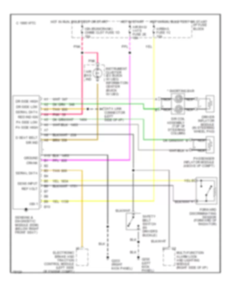
Supplemental Restraint Wiring Diagram for Buick LeSabre Limited 1996
List of elements for Supplemental Restraint Wiring Diagram for Buick LeSabre Limited 1996:
- * nca
- * shorting bar
- 1995 vftc c
- A10
- Air bag ind
- Air bag/ vats fuse 2e 10a
- Airbag fuse 1c 10a
- B10
- Connector (left side of i/p)
- Crank
- D seat belt
- Data link
- Dr side high
- Dr side low
- Driver inflator module (in steering wheel pad)
- Electronic brake and traction control module (left side of engine compt)
- Forward discriminating sensor (forward of radiator)
- G200 (left kick panel)
- G2o3 (right kick panel)
- Ground
- Hot in run, bulb test or start
- Hot in start
- I/p fuse block
- Ign (run/crank) chime clst fuse 1d 15a
- Ign 1
- Instrument cluster (ex buick w/ ub3) information center (buick w/ ub3)
- Multi-function alarm lock and lighting module (right side of i/p)
- Nca
- Pa side high
- Pa side low
- Passenger inflator module (above i/p compt)
- Pnk
- Red ind ign
- Ref volt
- Safety belt switch (in driver's buckle)
- Sens input
- Sensing & diagnostic module (sdm) (below right front seat)
- Serial data
- Sir coil assembly (top of steering column)
- Sir ind
- Tan
 Čeština
 Dansk
Dansk Deutsch
 Ελληνικά
 English
 English
 Español
 Suomi
Suomi Français
 Français
 עברית
עברית Hrvatski
 Italiano
 日本語
日本語 한국어
한국어 Nederlands
 Polski
 Português
 Português
 Română
 Русский
 Slovenčina
 Slovenščina
 Svenska
 Türkçe
 中文 (中国)
 Magyar