AIR CONDITIONING
4.2L
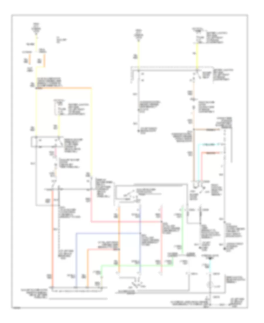
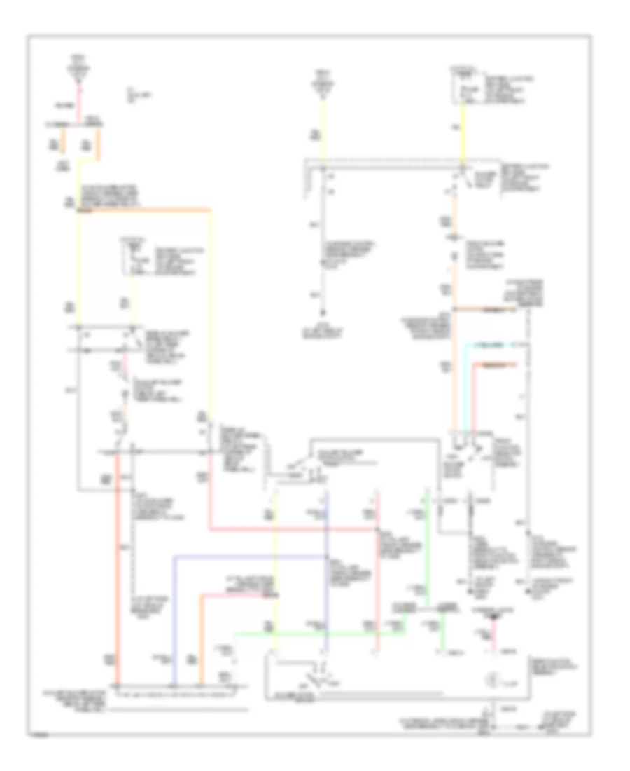
4.2L, Manual A/C Wiring Diagram, without Stripped Chassis (1 of 2) for Ford Econoline E250 2003
 https://portal-diagnostov.com/license.html
Automotive Electricians Portal FZCO
Automotive Electricians Portal FZCO
https://portal-diagnostov.com/license.html
https://portal-diagnostov.com/license.html
Automotive Electricians Portal FZCO
Automotive Electricians Portal FZCO
List of elements for 4.2L, Manual A/C Wiring Diagram, without Stripped Chassis (1 of 2) for Ford Econoline E250 2003:
- (1: temperature control potentiometer)
- (at right front of engine compt)
- (at right front of engine compt) g101
- (in engine control sensor harness, in breakout to battery junction box) s110
- (in engine control sensor harness, in breakout to battery junction box) s176
- (in fuel charge wiring harness, near breakout to intake manifold runner control module) s107
- (in window regulator relay switch harness, near breakout to ignition switch) s223
- (left side of dash) g204
- A/c clutch cycling pressure switch (in right front of engine compartment)
- A/c clutch relay
- A/c clutch solenoid (on left front of engine)
- A/c compressor clutch diode (near front of engine)
- A/c high pressure switch (in right front of engine compartment)
- A/c on input signal
- A/c relay control
- Battery junction box (bjb) (in left front of engine compartment)
- C294a
- C294d
- Central junction box (cjb) (left side of dash, near kick panel)
- Defrost
- Floor
- Front function selector switch assembly
- Fuse 10a
- Fuse 15a
- Fuse 30a
- G101
- Hot at all times
- Hot in run
- Hot in start or run
- Max a/c
- Mix
- Mode switch
- Norm a/c
- Of engine compt)
- Off
- Pcm power relay
- Pnk/ (in main wiring harness, near breakout to front function selector switch assembly) s203
- Powertrain control module (pcm) (in left rear of engine compartment, near brake master cylinder)
- Red
- S142 (in engine control sensor harness, at center rear red
- Temperature blend door actuator (behind right side of dash, on a/c heater plenum)
- To blower motor relay (diagram 2 of 2)
- To s400 (diagram 2 of 2)
- Vent
- Vent norm a/c
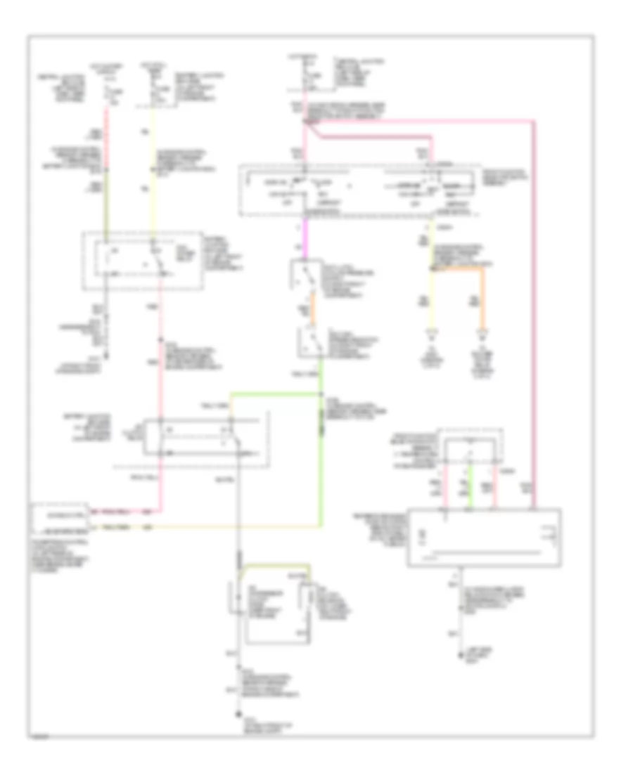
4.2L, Manual A/C Wiring Diagram, without Stripped Chassis (2 of 2) for Ford Econoline E250 2003
List of elements for 4.2L, Manual A/C Wiring Diagram, without Stripped Chassis (2 of 2) for Ford Econoline E250 2003:
- (at left side of dash) g203
- (at left side of engine compt) g100
- (at left side of vehicle rear end)
- (at left side of vehicle rear end) g400
- (at right front of engine compt) g101
- (in a/c blower motor wiring harness, near breakout to rear a/c blower speed relay 1) s400
- (in engine control sensor harness, near breakout to c219) s122
- (in interior lamps wiring harness, near breakout to interior lamp) s913
- (in right rear of engine compartment) blower motor resistor
- (in taillamp wiring harness, near breakout to c925) s303
- (not used)
- 87a
- Auxiliary blower motor (above left rear wheelwell)
- Auxiliary blower motor resistor assembly (above left rear wheelwell)
- Auxiliary blower motor switch
- Battery junction box (bjb) (in left front of engine compartment)
- Blower motor relay
- Blower motor switch
- C294b
- C294c
- C951a
- C951b
- Cutaway
- From s111 (diagram 1 of 2)
- Front blower motor (on right side of engine compartment)
- Front function selector switch assembly
- Fuse 50a
- G400
- High
- Hot at all times
- Illum
- Interior lights system
- Low
- Off
- Rear a/c blower speed relay 1 (in left rear corner of vehicle, above wheelwell)
- Rear a/c blower speed relay 2 (in left rear corner of vehicle, above wheelwell)
- Rear function selector switch assembly
- S143 (in engine control sensor harness, at right side of engine compt)
- S144 (in engine control sensor harness, at right side of engine compt)
- S202 (near breakout to front function selector switch assembly)
- S304 (in taillamp wiring harness, near breakout to c925)
- S305 (in taillamp wiring harness, near breakout to c925)
- S401 (in a/c blower motor wiring harness, in breakout to c405)
- Van & wagon
- W/ auxiliary a/c
- W/ rear control
- W/o rear control
4.6L
4.6L, Manual A/C Wiring Diagram (1 of 2) for Ford Econoline E250 2003
List of elements for 4.6L, Manual A/C Wiring Diagram (1 of 2) for Ford Econoline E250 2003:
- (1: temperature control potentiometer)
- (at right front of engine compt)
- (in engine control sensor harness, in breakout to battery junction box) s110
- (in engine control sensor harness, in breakout to battery junction box) s176
- (in window regulator relay switch harness, near breakout to ignition switch) s223
- (left side of dash) g204
- 87a
- A/c clutch cycling pressure switch (in right front of engine compartment)
- A/c clutch relay
- A/c clutch solenoid (on lower right front of engine)
- A/c compressor clutch diode (near front of engine)
- A/c high pressure switch (in right front of engine compartment)
- A/c on input sig
- A/c relay ctrl
- Battery junction box (bjb) (in left front of engine compartment)
- C294a
- C294d
- Central junction box (cjb) (left side of dash, near kick panel)
- Defrost
- Engine compartment)
- Floor
- Front function selector switch assembly
- Fuse 15a
- Fuse 30a
- G101
- G101 (at right front of engine compt)
- Hot at all times
- Hot in run
- Hot in start or run
- Max a/c
- Mix
- Mode switch
- Norm a/c
- Off
- Pcm power relay
- Pnk/ (in main wiring harness, near breakout to front function selector switch assembly) s203
- Powertrain control module (pcm) (in left rear of engine compartment, near brake master cylinder)
- Red
- S142 (in engine control sensor harness, at center rear of engine compartment)
- S166 (in engine control sensor harness, near breakout to c139)
- Temperature blend door actuator (behind right side of dash, on a/c heater plenum)
- To blower motor relay (diagram 2 of 2)
- To s400 (diagram 2 of 2)
- Vent
- Vent norm a/c
4.6L, Manual A/C Wiring Diagram (2 of 2) for Ford Econoline E250 2003
List of elements for 4.6L, Manual A/C Wiring Diagram (2 of 2) for Ford Econoline E250 2003:
- (at left side of dash) g203
- (at left side of engine compt) g100
- (at left side of vehicle rear end)
- (at left side of vehicle rear end) g400
- (at right front of engine compt) g101
- (in a/c blower motor wiring harness, near breakout to rear a/c blower speed relay 1) s400
- (in engine control sensor harness, near breakout to c219) s122
- (in interior lamps wiring harness, near breakout to interior lamp) s913
- (in right rear of engine compartment) blower motor resistor
- (in taillamp wiring harness, near breakout to c925) s303
- (not used)
- 87a
- Auxiliary blower motor (above left rear wheelwell)
- Auxiliary blower motor resistor assembly (above left rear wheelwell)
- Auxiliary blower motor switch
- Battery junction box (bjb) (in left front of engine compartment)
- Blower motor relay
- Blower motor switch
- C294b
- C294c
- C951a
- C951b
- Cutaway
- From s111 (diagram 1 of 2)
- Front blower motor (on right side of engine compartment)
- Front function selector switch assembly
- Fuse 50a
- G400
- High
- Hot at all times
- Illum
- Interior lights system
- Low
- Off
- Rear a/c blower speed relay 1 (in left rear corner of vehicle, above wheelwell)
- Rear a/c blower speed relay 2 (in left rear corner of vehicle, above wheelwell)
- Rear function selector switch assembly
- S143 (in engine control sensor harness, at right side of engine compt)
- S144 (in engine control sensor harness, at right side of engine compt)
- S202 (in main wiring harness, near breakout to front function selector switch assembly)
- S304 (in taillamp wiring harness, near breakout to c925)
- S305 (in taillamp wiring harness, near breakout to c925)
- S401 (in a/c blower motor wiring harness, in breakout to c405)
- Van & wagon
- W/ auxiliary a/c
- W/ rear control
- W/o rear control
5.4L
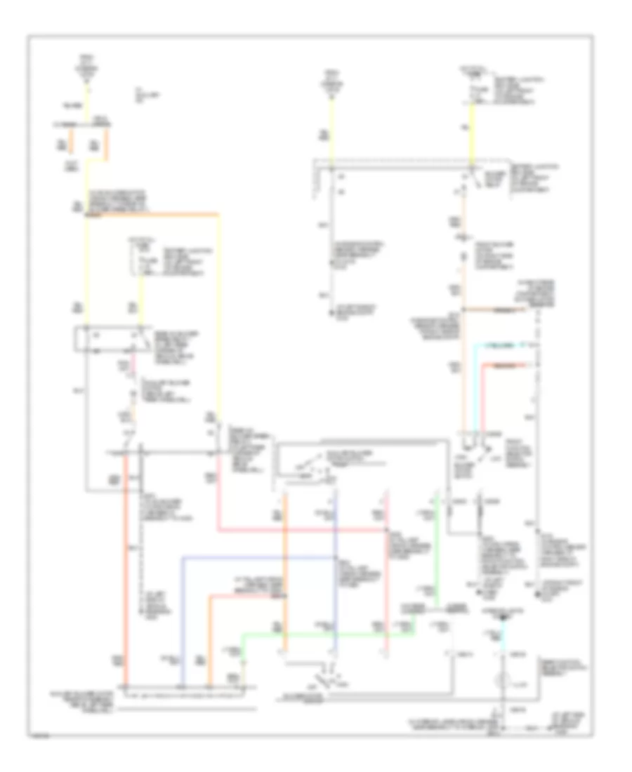
5.4L, Manual A/C Wiring Diagram, without Stripped Chassis (1 of 2) for Ford Econoline E250 2003
List of elements for 5.4L, Manual A/C Wiring Diagram, without Stripped Chassis (1 of 2) for Ford Econoline E250 2003:
- (at right front of engine compt) g101
- (in engine control sensor & fuel charge wiring harness, near breakout to a/c clutch solenoid) s189
- (in window regulator relay switch harness, near breakout to ignition switch) s223
- (left side of dash) g204
- (temperature control potentiometer)
- 5.4l, 5.4l cng & 6.8l
- 7.3l di turbo diesel
- A/c clutch cycling pressure switch (in right front of engine compartment)
- A/c clutch solenoid (on lower right front of engine)
- A/c clutch solenoid (on top left front of engine)
- A/c compressor clutch diode (near front of engine)
- A/c high pressure switch (in right front of engine compartment)
- A/c on input signal
- C294a
- C294d
- Central junction box box (cjb) (left side of dash, near kick panel)
- Defrost
- Floor
- Front function selector switch assembly
- Front function selector switch assembly front12
- Fuse 15a
- Hot in run
- Max a/c
- Mix
- Mode switch
- Norm a/c
- Off
- Pnk/ (in main wiring harness, near breakout to front function selector switch assembly) s203
- Powertrain control module (pcm) (in left rear of engine compartment, near brake master cylinder)
- S111 (in engine control sensor harness, in breakout to battery junction box)
- S141 (in engine control sensor harness, near breakout to c139) (7.3l: in engine control sensor harness, near breakout to c1168)
- S143 (in engine control sensor harness, at right side of engine compartment)
- Temperature blend door actuator (behind right side of dash, on a/c heater plenum)
- To blower motor relay (diagram 2 of 2)
- To s400 (diagram 2 of 2)
- Vent
- Vent norm a/c
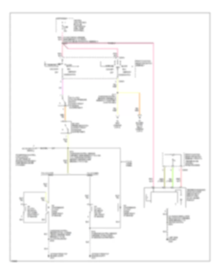
5.4L, Manual A/C Wiring Diagram, without Stripped Chassis (2 of 2) for Ford Econoline E250 2003
List of elements for 5.4L, Manual A/C Wiring Diagram, without Stripped Chassis (2 of 2) for Ford Econoline E250 2003:
- (at left side of dash) g203
- (at left side of vehicle rear end)
- (at left side of vehicle rear end) g400
- (at right front of engine compt) g101
- (in a/c blower motor wiring harness, near breakout to rear a/c blower speed relay 1) s400
- (in engine control sensor harness, near breakout to c219) s122
- (in interior lamps wiring harness, near breakout to interior lamp) s913
- (in right rear of engine compartment) blower motor resistor
- (in taillamp wiring harness, near breakout to c925) s303
- (not used)
- 87a
- Auxiliary blower motor (above left rear wheelwell)
- Auxiliary blower motor resistor assembly (above left rear wheelwell)
- Auxiliary blower motor switch
- Battery junction box (bjb) (in left front of engine compartment)
- Blower motor relay
- Blower motor switch
- C294b
- C294c
- C951a
- C951b
- Cutaway
- From s111 (diagram 1 of 2)
- Front blower motor (on right side of engine compartment)
- Front function selector switch assembly
- Fuse 50a
- G100 (at left side of engine compt)
- G400
- High
- Hot at all times
- Illum
- Interior lights system
- Low
- Off
- Rear a/c blower speed relay 1 (in left rear corner of vehicle, above wheelwell)
- Rear a/c blower speed relay 2 (in left rear corner of vehicle, above wheelwell)
- Rear function selector switch assembly
- S143 (in engine control sensor harness, at right side of engine compt)
- S144 (in engine control sensor harness, at right side of engine compt)
- S202 (near breakout to front function selector switch assembly)
- S304 (in taillamp wiring harness, near breakout to c925)
- S305 (in taillamp wiring harness, near breakout to c925)
- S401 (in a/c blower motor wiring harness, in breakout to c405)
- Van & wagon
- W/ auxiliary a/c
- W/ rear control
- W/o rear control

 Čeština
 Dansk
Dansk Deutsch
 Ελληνικά
 English
 English
 Español
 Suomi
Suomi Français
 Français
 עברית
עברית Hrvatski
 Italiano
 日本語
日本語 한국어
한국어 Nederlands
 Polski
 Português
 Português
 Română
 Русский
 Slovenčina
 Slovenščina
 Svenska
 Türkçe
 中文 (中国)