ANTI-LOCK BRAKES
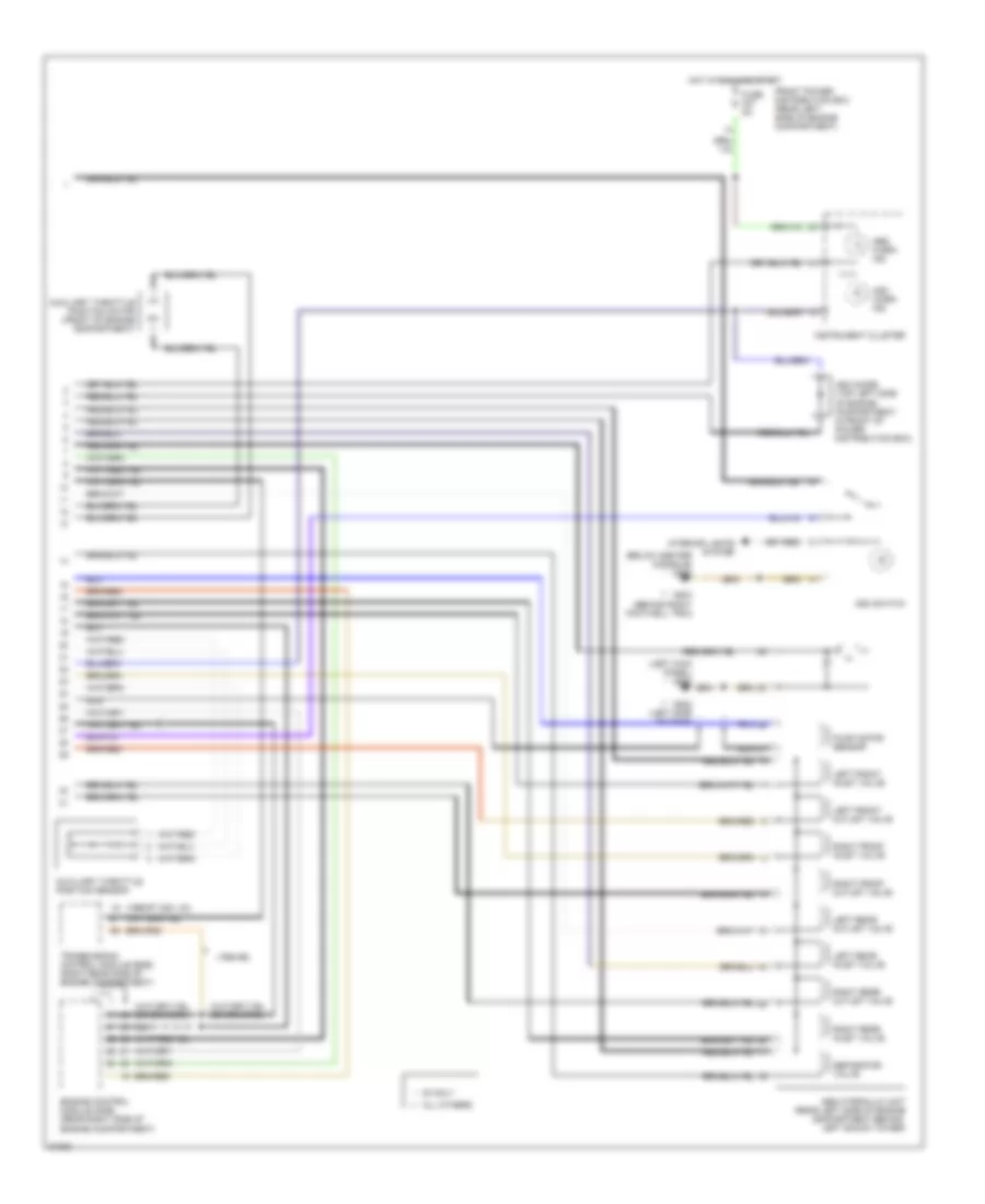
Anti-lock Brake Wiring Diagrams, with Traction Control (1 of 2) for BMW 325is 1995


List of elements for Anti-lock Brake Wiring Diagrams, with Traction Control (1 of 2) for BMW 325is 1995:
- (left kick panel) g200
- 1994 325i, 1997 z3 only
- Abs brake pedal travel sensor (near brake fluid reservoir)
- Abs lp ctrl
- Abs pump motor relay (in front power distribution box)
- Abs pump mtr rly
- Abs pwr protect rly
- Abs relay (in front power distribution box)
- Abs travel sens sig
- Ads step motor
- All others **
- Asc lp ctrl
- Asc sw sig
- Asc throt flap pot
- Battery volt
- Brake light switch (on bracket, above brake pedal)
- Brake sig
- Data link connector (rear of engine compartment)
- Eml-signal
- Engine control system
- Front power distribution box (rear left side of engine compartment)
- Fuse f10 30a
- Fuse f21 5a
- Fuse f38 30a
- Fuse f46 15a
- G108 (left front of eng compt)
- G202 (left side of dash)
- G203 (right kick panel)
- Ground
- Ground, module
- Hot at all times
- Hot in accy, run and start
- Hot in run and start
- Idle spd sig
- Ign sig
- L fnt sol vlv sig
- L rear sol vlv sig
- Left front abs speed sensor
- Left rear abs speed sensor
- Lf speed sens signal
- Lr speed sens signal
- Nca
- Pump mtr sens shield
- Pump mtr sens signal
- Rf speed sens signal
- Right front abs speed sensor
- Right rear abs speed sensor
- Rr speed sens signal
- Rt fnt sol vlv sig
- Rxd sig
- Sens gnd
- Signal
- Signal abs travel sens
- Slip control module (abs) (right side of dash, behind glove box)
- Sol vlv
- Spd sig
- Throt flap postn
- Trans influence
- Txd sig
- Z3 only *
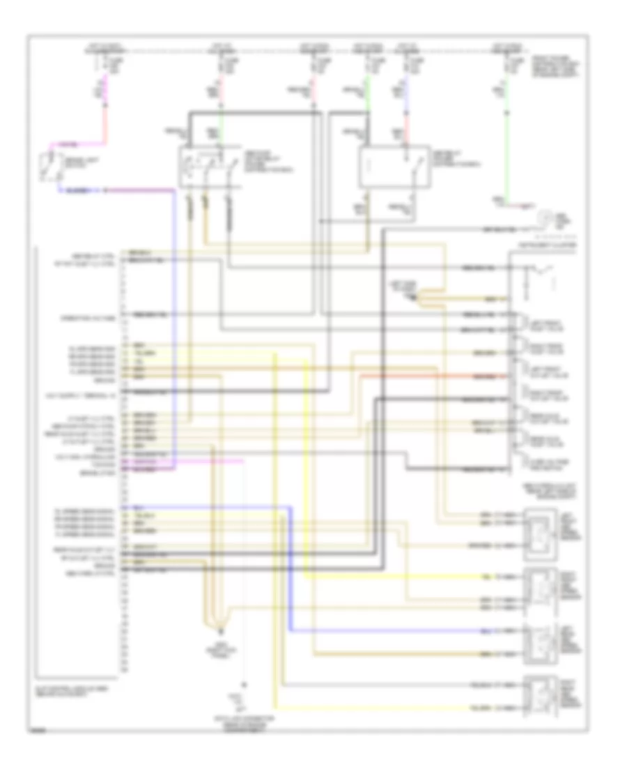
Anti-lock Brake Wiring Diagrams, with Traction Control (2 of 2) for BMW 325is 1995
List of elements for Anti-lock Brake Wiring Diagrams, with Traction Control (2 of 2) for BMW 325is 1995:
- (1994-95)
- (1996-97 328i, m3)
- (below center console) g302
- (left kick panel) g200
- * **
- Abs hydraulic unit (rear left side of engine compartment behind left shock tower)
- Abs warn ind
- All others **
- Asc diode (top left side of engine compartment, in front of power distribution box)
- Asc switch
- Asc warn ind
- Auxiliary throttle position motor (front of engine compartment)
- Auxiliary throttle position sensor
- Engine control module (dme) (rear right side of engine compartment)
- Front power distribution box (rear left side of engine compartment)
- Fuse f27 5a
- G202 (left side of dash)
- G203 (behind right footwell trim)
- Hot in run and start
- Instrument cluster
- Interior lights system
- Left front inlet valve
- Left front outlet valve
- Left rear inlet valve
- Left rear outlet valve
- Nca
- Pump motor sensor
- Right front inlet valve
- Right front outlet valve
- Right rear inlet valve
- Right rear outlet valve
- Separator valve
- Transmission control module (egs) (right rear side of engine compartment)
- Z3 only *
Anti-lock Brake Wiring Diagrams, without Traction Control for BMW 325is 1995
List of elements for Anti-lock Brake Wiring Diagrams, without Traction Control for BMW 325is 1995:
- (left side of dash) g202
- Abs hydraulic unit (rear left side of engine compt)
- Abs pump motor relay (power distribution box)
- Abs pump mtr rly ctrl
- Abs relay (power distribution box)
- Abs relay ctrl
- Abs warn ind
- Abs warn lp ctrl
- Brake light switch
- Brake lp sig
- Data link connector (rear of engine compartment)
- Fl spd sens gnd
- Fl speed sens signal
- Fr spd sens gnd
- Fr speed sens signal
- Front power distribution box (rear left side of engine compt)
- Fuse f10 30a
- Fuse f21 5a
- Fuse f23 5a
- Fuse f27 5a
- Fuse f38 30a
- Fuse f46 30a
- G203 (right kick panel)
- Ground
- Hot at all times
- Hot in accy, run and start
- Hot in run and start
- Instrument cluster
- Left front abs speed sensor
- Left front inlet valve
- Left front outlet valve
- Left rear abs speed sensor
- Lf inlet vlv ctrl
- Lf outlet vlv ctrl
- Nca
- Operating voltage
- Over voltage protection
- Rear axle inlet valve
- Rear axle inlet vlv ctrl
- Rear axle outlet valve
- Rear axle outlet vlv
- Rf outlet vlv ctrl
- Right front abs speed sensor
- Right front inlet valve
- Right front outlet valve
- Right rear abs speed sensor
- Rl spd sens gnd
- Rl speed sens signal
- Rr spd sens gnd
- Rr speed sens signal
- Rt fnt inlet vlv ctrl
- Slip control module (abs) (behind glove box)
- Txd diag
- Volt mon, hydraulics

 Čeština
 Dansk
Dansk Deutsch
 Ελληνικά
 English
 English
 Español
 Suomi
Suomi Français
 Français
 עברית
עברית Hrvatski
 Italiano
 日本語
日本語 한국어
한국어 Nederlands
 Polski
 Português
 Português
 Română
 Русский
 Slovenčina
 Slovenščina
 Svenska
 Türkçe
 中文 (中国)