ANTI-LOCK BRAKES
4.0L
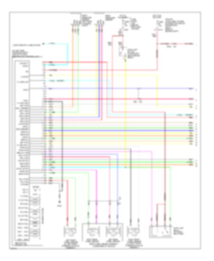
4.0L, Anti-lock Brakes Wiring Diagram (1 of 2) for Nissan Pathfinder S 2012
 https://portal-diagnostov.com/license.html
Automotive Electricians Portal FZCO
Automotive Electricians Portal FZCO
https://portal-diagnostov.com/license.html
https://portal-diagnostov.com/license.html
Automotive Electricians Portal FZCO
Automotive Electricians Portal FZCO
List of elements for 4.0L, Anti-lock Brakes Wiring Diagram (1 of 2) for Nissan Pathfinder S 2012:
- (on left side of engine compt) abs actuator & electric unit (control unit)
- 15c
- 16c
- 17c
- 18c
- 44g
- Abs/tcs/vdc control unit
- Brake level sw
- Can-h
- Can-l
- Can2-h
- Can2-l
- Clus gnd
- Clus sp
- Computer data lines system
- Diag k
- E119
- E126
- E152
- E160
- E26
- E41
- Exterior lights system
- Fl in sol
- Fl out sol
- Fr in sol
- Fr lh pwr
- Fr lh sig
- Fr out sol
- Fr rh pwr
- Fr rh sig
- Fuse 10a
- Fuse block (j/b) (behind right end of dash)
- Gnd p
- Gnd v
- Hot at all times
- Hot in on or start
- Hsv1 (mc1) usv2 (mc2) usv1 (mc1)
- Hsv2 (mc2)
- Ign
- Ipdm e/r (intelligent power distribution module engine room) (right rear of engine compt)
- Kl30 v
- Kl30-p
- Left front wheel sensor (at left front steering knuckle assembly)
- Left rear wheel sensor
- M31
- M91
- Mot (+)
- Mot (-)
- Motor
- Pnk
- Rear wheel sensor assembly (under rear of vehicle)
- Red
- Right front wheel sensor (at right front steering knuckle assembly)
- Right rear wheel sensor
- Rl in sol
- Rl out sol
- Rr in sol
- Rr lh pwr
- Rr lh sig
- Rr out sol
- Rr rh pwr
- Rr rh sig
- Solenoid valves
- Stop lamp sw
- Stop lamp switch (on bracket, above brake pedal)
- Vdc off sw
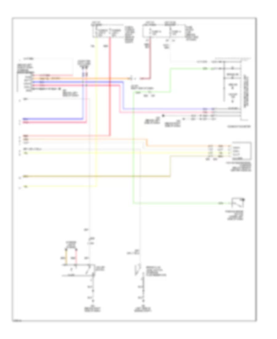
4.0L, Anti-lock Brakes Wiring Diagram (2 of 2) for Nissan Pathfinder S 2012
List of elements for 4.0L, Anti-lock Brakes Wiring Diagram (2 of 2) for Nissan Pathfinder S 2012:
- (behind left side of dash)
- Abs ind
- B40
- Batt
- Brake fluid level switch (on brake fluid reservoir)
- Brake ind
- Can-h
- Can-l
- Clu gnd
- Clu p
- Combination meter
- Computer data lines system
- E26
- E34
- E9 (left side of engine compt)
- Fuse & fusible link box (right rear of engine compt)
- Fuse 14 10a
- Fuse 18 10a
- Fuse block (j/b) (behind right end of dash)
- Fusible link l 30a
- Fusible link n 40a
- Gnd
- Hot at all times
- Hot in on or start
- Illum
- Interior lights system
- J/c m01 (right end of dash)
- M57 (behind left side of dash)
- M61 (behind right side of dash)
- M91
- Parking brake switch (under left side of dash)
- Pnk
- Pwr
- Red
- Slip ind
- Steering angle sensor
- Unified meter control unit (w/ information display)
- Vdc off ind
- Vdc off switch
- Yaw rate/side/decel g sensor (below rear of center console)
5.6L
5.6L, Anti-lock Brakes Wiring Diagram (1 of 2) for Nissan Pathfinder S 2012
List of elements for 5.6L, Anti-lock Brakes Wiring Diagram (1 of 2) for Nissan Pathfinder S 2012:
- (mc1)
- (mc2)
- (on left side of engine compt) abs actuator & electric unit (control unit)
- 15c
- 17c
- 18c
- 44g
- Abs/tcs/vdc control unit
- Bpfs nc
- Bpfs no
- Bpfs sig
- Brk-out (off)
- Bst pwm
- Bst pwr
- C1 16c
- Can-h
- Can-l
- Can2-h
- Can2-l
- Clstr gnd
- Clus sp
- Computer data lines system
- Dels gnd
- Dels sensep
- Dels sig
- Diag-k
- Driv1 gnd
- Driv1 sensep
- Driv1 sig
- Driv2 gnd
- Driv2 sig
- Driv2 sp
- E119
- E126
- E152
- E160
- E26
- E41
- Fl in sol
- Fl level sw
- Fl out sol
- Fr in sol
- Fr lh pwr
- Fr lh sig
- Fr out sol
- Fr rh pwr
- Fr rh sig
- Front pressure sensor (left rear of engine compt)
- Fuse 10a
- Fuse block (j/b) (behind right end of dash)
- Gnd
- Hot at all times
- Hot in on or start
- Hsv1
- Hsv2
- Ign
- Ipdm e/r (intelligent power distribution module engine room) (right rear of engine compt)
- Left front wheel sensor (at left front steering knuckle assembly)
- Left rear wheel sensor
- M31
- M91
- Mot (+)
- Mot (-)
- Motor
- Mtr gnd
- Mtr sply
- Pnk
- Pwr
- Rear pressure sensor
- Rear wheel sensor assembly (under rear of vehicle)
- Red
- Right front wheel sensor (at right front steering knuckle assembly)
- Right rear wheel sensor
- Rl in sol
- Rl out sol
- Rr in sol
- Rr lh pwr
- Rr lh sig
- Rr out sol
- Rr rh pwr
- Rr rh sig
- Sig
- Solenoid valves
- Stop lamp relay (in fuse & relay box)
- Stop lamp switch (on bracket, above brake pedal)
- Stop lmp sw
- Usv1
- Usv2
- Vdc off sw
- Vlv ecu gnd
- Vlv ecu sply
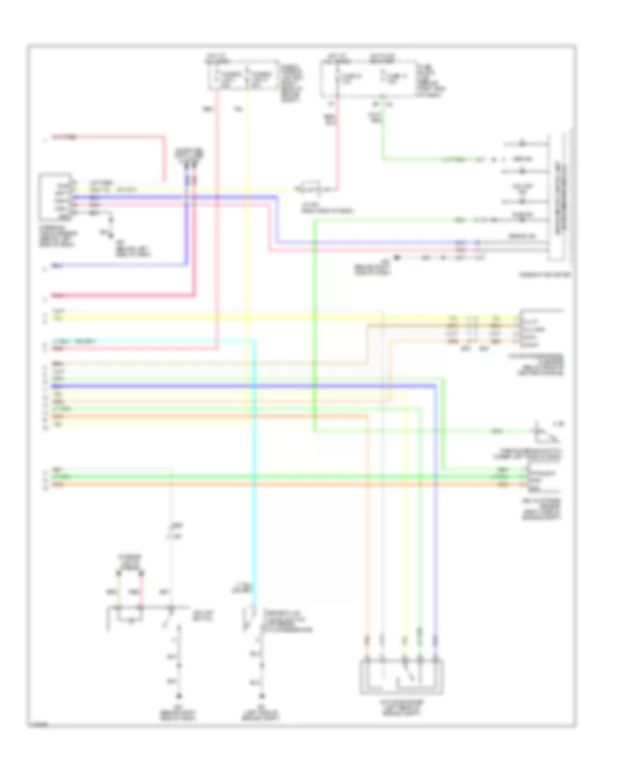
5.6L, Anti-lock Brakes Wiring Diagram (2 of 2) for Nissan Pathfinder S 2012
List of elements for 5.6L, Anti-lock Brakes Wiring Diagram (2 of 2) for Nissan Pathfinder S 2012:
- Abs ind
- Active booster (left rear of engine compt)
- B40
- Batt
- Brake fluid level switch (on brake fluid reservoir)
- Brake ind
- Can-h
- Can-l
- Clu gnd
- Clu p
- Combination meter
- Computer data lines system
- Delta stroke sensor (right side of engine compt)
- E26
- E34
- E9 (left side of engine compt)
- Fuse & fusible link box (right rear of engine compt)
- Fuse 14 10a
- Fuse 18 10a
- Fuse block (j/b) (behind right end of dash)
- Fusible link l 30a
- Fusible link n 40a
- Gnd
- Hot at all times
- Hot in on or start
- Interior lights system
- J/c m01 (right end of dash)
- M57 (behind left side of dash)
- M61 (behind right side of dash)
- M91
- Parking brake switch (under left side of dash)
- Pnk
- Pwr
- Pwr_sup
- Red
- Sig
- Slip ind
- Steering angle sensor (behind left side of dash)
- Unified meter control unit (w/ information display)
- Vdc off ind
- Vdc off switch
- Yaw rate/side/decel g sensor (below rear of center console)

 Čeština
 Dansk
Dansk Deutsch
 Ελληνικά
 English
 English
 Español
 Suomi
Suomi Français
 Français
 עברית
עברית Hrvatski
 Italiano
 日本語
日本語 한국어
한국어 Nederlands
 Polski
 Português
 Português
 Română
 Русский
 Slovenčina
 Slovenščina
 Svenska
 Türkçe
 中文 (中国)