ANTI-THEFT
Forced Entry Wiring Diagram for Mitsubishi Montero Sport XLS 2004
 https://portal-diagnostov.com/license.html
Automotive Electricians Portal FZCO
Automotive Electricians Portal FZCO
https://portal-diagnostov.com/license.html
https://portal-diagnostov.com/license.html
Automotive Electricians Portal FZCO
Automotive Electricians Portal FZCO
List of elements for Forced Entry Wiring Diagram for Mitsubishi Montero Sport XLS 2004:
- (not used)
- (on inner fender panel, at left rear of engine compartment) g10
- (under left front kick panel, near auto-cruise ecu) g9
- 15a
- D01
- D11
- D13
- D14
- D26
- D27
- Data link connector 1 (under left side of dash, near relay box)
- Diode (theft alarm horn circuit) (left end of dash)
- Door locks system
- Door locks, interior lights system
- Engine compartment relay box (on left inner fender panel)
- Etacs ecu
- Fuse 10a
- Fuse 3
- G10 (on inner fender panel, at left rear of engine compartment)
- G4 (under center of dash)
- G6 (near right rear seat belt retractor)
- G7 (on left side of tailgate)
- G8 (near left rear seat belt retractor)
- G9 (under left front kick panel, near auto-cruise ecu)
- Headlights system
- Hood switch
- Horns system
- Hot at all times
- Hot in run or start
- Ind
- Interior lights system
- Iod or storage connector
- Joint connector 1 (behind upper right side of dash)
- Joint connector 2 (behind upper right side of dash)
- Joint connector 5 (behind upper right side of dash)
- Junction block (behind left side of dash)
- Key reminder switch (closed when key is removed)
- Left door lock key cylinder switch
- Left front door lock actuator (rear of left front door)
- Left front door switch
- Left rear door lock actuator (rear of left rear door)
- Left rear door switch
- Liftgate lock key cylinder switch
- Liftgate switch
- Lock
- Multi- purpose fuse 8 10a
- Nca
- Off
- Red
- Right door lock key cylinder switch
- Right front door lock actuator (rear of right front door)
- Right front door switch
- Right rear door lock actuator (rear of right rear door)
- Right rear door switch
- Security indicator
- Theft alarm horn
- Theft alarm horn relay (behind right side of glove box)
- Unlock
- W/ keyless entry
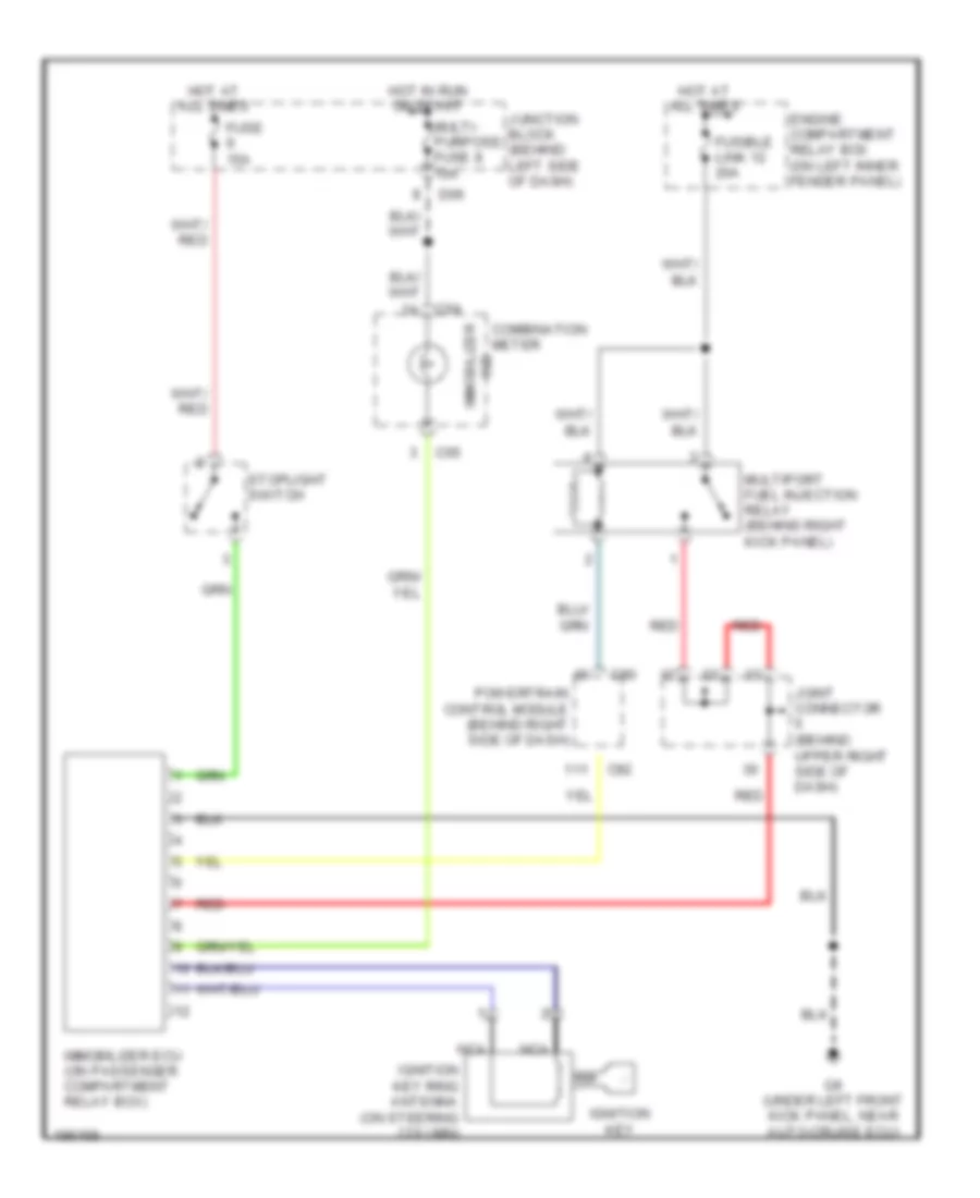
Immobilizer Wiring Diagram for Mitsubishi Montero Sport XLS 2004
List of elements for Immobilizer Wiring Diagram for Mitsubishi Montero Sport XLS 2004:
- C04
- C05
- C90
- C92
- Combination meter
- D06
- Engine compartment relay box (on left inner fender panel)
- Fuse 15a
- Fusible link 12 20a
- G9 (under left front kick panel, near auto-cruise ecu)
- Hot at all times
- Hot in run or start
- Ignition key
- Ignition key ring antenna (on steering column)
- Immobilizer ecu (on passenger compartment relay box)
- Immobilizer ind
- Joint connector (behind upper right side of dash)
- Junction block (behind left side of dash)
- Multi- purpose fuse 8 10a
- Multiport fuel injection relay (behind right kick panel)
- Nca
- Powertrain control module (behind right side of dash)
- Red
- Stoplight switch

 Čeština
 Dansk
Dansk Deutsch
 Ελληνικά
 English
 English
 Español
 Suomi
Suomi Français
 Français
 עברית
עברית Hrvatski
 Italiano
 日本語
日本語 한국어
한국어 Nederlands
 Polski
 Português
 Português
 Română
 Русский
 Slovenčina
 Slovenščina
 Svenska
 Türkçe
 中文 (中国)