ENGINE ACCESSORIES
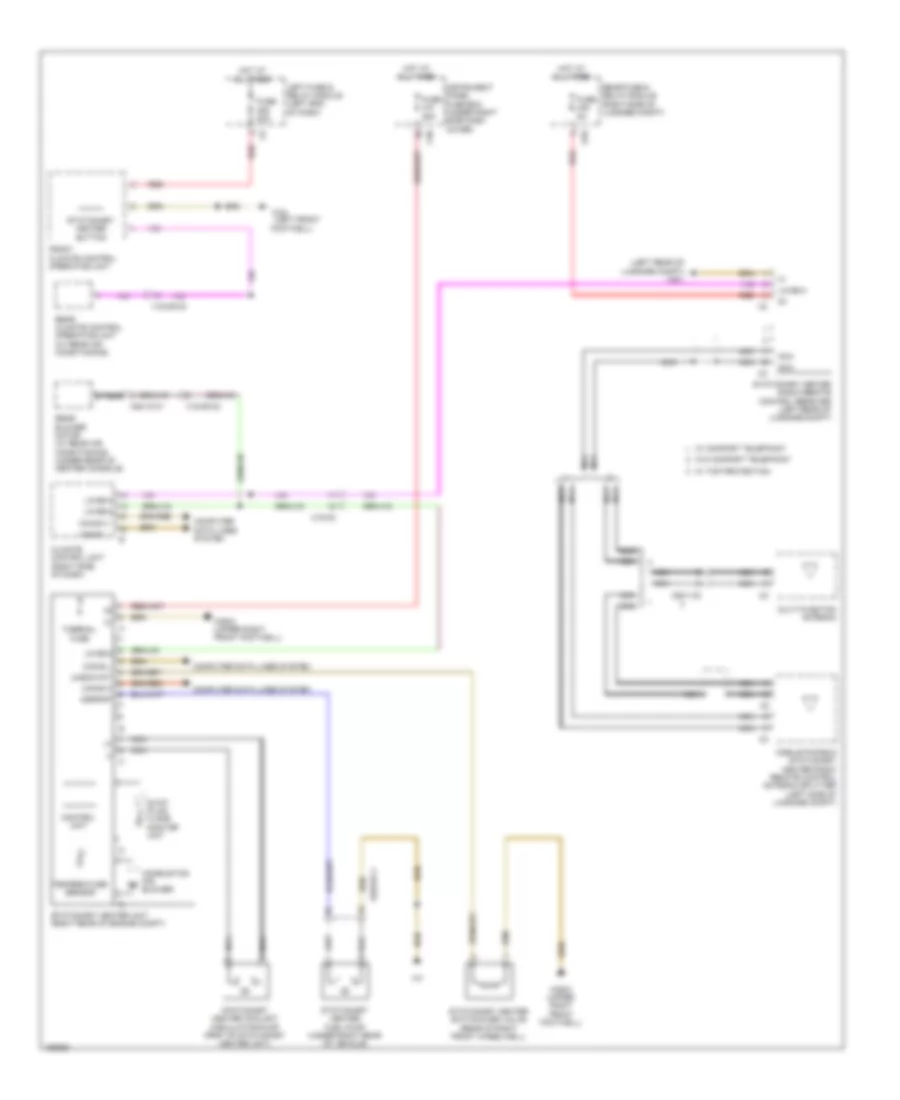
Stationary Heater Wiring Diagram for Mercedes-Benz S550 4Matic 2014
List of elements for Stationary Heater Wiring Diagram for Mercedes-Benz S550 4Matic 2014:
- (+)
- (-)
- (left front
- (left rear of luggage compt) w6/1
- C30
- Can-b h
- Can-b l
- Climate control unit (right side of dash)
- Combustion air blower
- Computer data lines system
- Control unit
- Dsrpmp
- Footwell)
- Front climate control operating unit
- Fuse 20a
- Fuse 25a
- Fuse 5a
- Glow plug/ flame monitor unit
- Hot at all times
- Instrument panel fuse box (under right side dash cover)
- Left fuse & relay module (left end of dash)
- Lin b8-2
- Lin b8-3
- Mobile phone & stationary heater radio remote control antenna splitter (left side of luggage compt)
- Multi-function antenna
- Nca
- Rear blower motor (w/ rear air conditioning) (under rear of center console)
- Rear climate control operating unit (w/ rear air conditioning)
- Rear fuse & relay module (right side of luggage compt)
- Red
- S10
- Stationary heater button
- Stationary heater coolant circulation pump (part of stationary heater unit)
- Stationary heater fuel pump (under right rear of vehicle)
- Stationary heater radio remote control receiver (left rear of luggage compt)
- Stationary heater switchover valve (rear of right front wheelwell)
- Stationary heater unit (right rear of engine compt)
- Temperature sensor
- Thermal fuse
- Umschvnt
- W/ comfort telephony
- W/ top protection
- W/o comfort telephony
- W34
- W85/2 (upper right front footwell)
- X18-c2
- X18/35-c2
- X50/1-c3
- X62/33-c1
- X64/10-c1
 Čeština
 Dansk
Dansk Deutsch
 Ελληνικά
 English
 English
 Español
 Suomi
Suomi Français
 Français
 עברית
עברית Hrvatski
 Italiano
 日本語
日本語 한국어
한국어 Nederlands
 Polski
 Português
 Português
 Română
 Русский
 Slovenčina
 Slovenščina
 Svenska
 Türkçe
 中文 (中国)
 Magyar