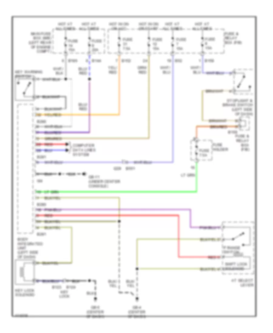
SHIFT INTERLOCK
Park Brake Release Wiring Diagram for Subaru Impreza Limited 2013
 https://portal-diagnostov.com/license.html
Automotive Electricians Portal FZCO
Automotive Electricians Portal FZCO
https://portal-diagnostov.com/license.html
https://portal-diagnostov.com/license.html
Automotive Electricians Portal FZCO
Automotive Electricians Portal FZCO
List of elements for Park Brake Release Wiring Diagram for Subaru Impreza Limited 2013:
- B281
- B52
- B551
- B552
- Body integrated unit (left side of dash)
- Brake fluid level switch (on brake fluid reservoir)
- Can
- Combination meter
- Computer data lines system
- Drive circuit
- Fuse & relay box (f/b)
- Fuse 10a
- Fuse 15a
- Gb-11 (under center console)
- Gb-3 (right end of dash)
- Gb-4 (center of dash)
- Hot at all times
- Hot in on or start
- I/f
- I102
- I229
- I230
- I84
- Micro computer
- Parking brake switch (base of park brake lever)
- Parking brake/ brake fluid level warning light ind
- Power
- R167
- Red
- Transceiver & receiver
Shift Interlock Wiring Diagram for Subaru Impreza Limited 2013
List of elements for Shift Interlock Wiring Diagram for Subaru Impreza Limited 2013:
- At select lever
- B123
- B124
- B144
- B152
- B158
- B159
- B186
- B280
- B281
- B52
- B551 i229
- Body integrated unit (left side of dash)
- Computer data lines system
- Fuse & relay box (f/b)
- Fuse 15a
- Fuse 20a
- Fuse 7.5a
- Fuse holder
- Gb-11 (under center console)
- Gb-4 (center of dash)
- Gb-5 (center of dash)
- Hot at all times
- Hot in on or acc
- Hot in on or start
- I84
- Key lock
- Key lock solenoid
- Key warning switch
- Main fuse box (m/b) (left rear of engine compt)
- P range switch
- Red
- Shift lock solenoid
- Stoplight & brake switch (left side of dash)

 Čeština
 Dansk
Dansk Deutsch
 Ελληνικά
 English
 English
 Español
 Suomi
Suomi Français
 Français
 עברית
עברית Hrvatski
 Italiano
 日本語
日本語 한국어
한국어 Nederlands
 Polski
 Português
 Português
 Română
 Русский
 Slovenčina
 Slovenščina
 Svenska
 Türkçe
 中文 (中国)