SHIFT INTERLOCKS
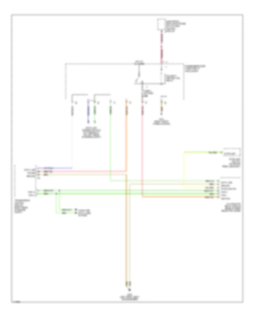
Shift Interlock Wiring Diagram for Mercedes-Benz E320 4Matic 2000
List of elements for Shift Interlock Wiring Diagram for Mercedes-Benz E320 4Matic 2000:
- A pnk/red
- Can (+)
- Can (-)
- Can h
- Can l
- Computer data lines system
- Data line
- Data link connector (dlc) (dtc readout) (on left rear of engine compt)
- Electronic ignition-starter switch (eis) control module
- Fuse 3 etc/ads 10a
- G101 (right front wheelhousing)
- G300 (left front seat crossmember)
- Ground
- Hot at all times
- Ignition
- Passenger's side fuse & relay module box
- Pnk/red
- Polarity protection relay
- Power
- Stoplamp
- Stoplamp sw
- Stoplamp switch (on brake pedal bracket)
- Transmission control module (right rear of engine compt)
- Valve block relay module (base of gear selector lever)
 Čeština
 Dansk
Dansk Deutsch
 Ελληνικά
 English
 English
 Español
 Suomi
Suomi Français
 Français
 עברית
עברית Hrvatski
 Italiano
 日本語
日本語 한국어
한국어 Nederlands
 Polski
 Português
 Português
 Română
 Русский
 Slovenčina
 Slovenščina
 Svenska
 Türkçe
 中文 (中国)
 Magyar