AIR CONDITIONING
A/C Wiring Diagram for Toyota Corolla CE 1998
 https://portal-diagnostov.com/license.html
Automotive Electricians Portal FZCO
Automotive Electricians Portal FZCO
https://portal-diagnostov.com/license.html
https://portal-diagnostov.com/license.html
Automotive Electricians Portal FZCO
Automotive Electricians Portal FZCO
List of elements for A/C Wiring Diagram for Toyota Corolla CE 1998:
- (engine room main wire harness, at top of left kick panel) i1
- (front side of left fender) g100
- (right radiator support) engine room r/b no.6
- A/c
- A/c amplifier (behind dash, above glove box)
- A/c condenser fan motor
- A/c evaporator temp. sensor (top center of dash)
- A/c fuse 7.5a
- A/c magnetic clutch & lock sensor
- A/c sw
- A/c triple pressure sw (a/c dual & single pressure switch) (right front of engine compartment)
- A/c+
- Ac fan no.2 relay
- Ac fan no.3 relay
- Ac mg relay
- Ac1
- Act
- Blower motor (right side of dash)
- Blower resistor (right side of dash)
- Blower switch
- C14
- Cds fuse 30a
- Center j/b (center of dash)
- Def
- Dual
- E10
- Ecu-ig fuse 10a
- Engine control module (below center of dash)
- Engine room j/b (left side of engine compartment)
- Engine room r/b no.5 (left side of engine compartment)
- Fan no.1 relay
- G203 (right kick panel)
- G206 (left dash brace)
- Gauge fuse 10a
- Gnd
- Hot at all times
- Hot in on
- Hot in on or start
- Htr fuse 50a
- Htr relay
- I6 (cowl wire harness, top center of dash)
- Ign
- Instrument panel j/b (lower finish panel)
- Integration relay
- J/c 1 (at top of left kick panel)
- J/c 10 (left side of dash)
- J/c 13 (right side of dash)
- J/c 14
- J/c 8
- La/c
- Led
- Lock
- Me1
- Me2
- Mgc
- Nummi made
- Off
- Or start
- Prs
- Radiator fan motor
- Rdi fuse 30a
- Red
- Side of right fender) g101
- Single
- Tach
- Tmmc made
- Water temp switch (right front of engine compartment)
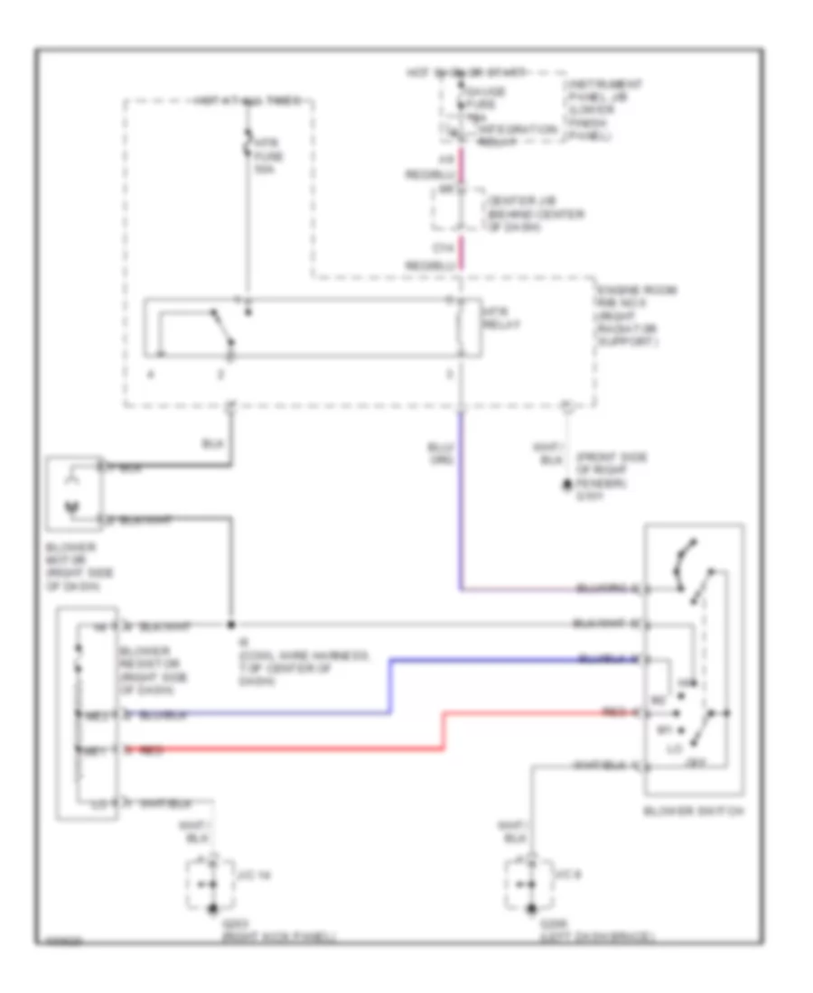
Heater Wiring Diagram for Toyota Corolla CE 1998
List of elements for Heater Wiring Diagram for Toyota Corolla CE 1998:
- (front side of right fender) g101
- Blower motor (right side of dash)
- Blower resistor (right side of dash)
- Blower switch
- C14
- Center j/b (behind center of dash)
- Engine room r/b no.6 (right radiator support)
- G203 (right kick panel)
- G206 (left dash brace)
- Gauge fuse 10a
- Hot at all times
- Hot in on or start
- Htr fuse 50a
- Htr relay
- I6 (cowl wire harness, top center of dash)
- Instrument panel j/b (lower finish panel)
- Integration relay
- J/c 14
- J/c 8
- Me1
- Me2
- Off
- Red

 Čeština
 Dansk
Dansk Deutsch
 Ελληνικά
 English
 English
 Español
 Suomi
Suomi Français
 Français
 עברית
עברית Hrvatski
 Italiano
 日本語
日本語 한국어
한국어 Nederlands
 Polski
 Português
 Português
 Română
 Русский
 Slovenčina
 Slovenščina
 Svenska
 Türkçe
 中文 (中国)