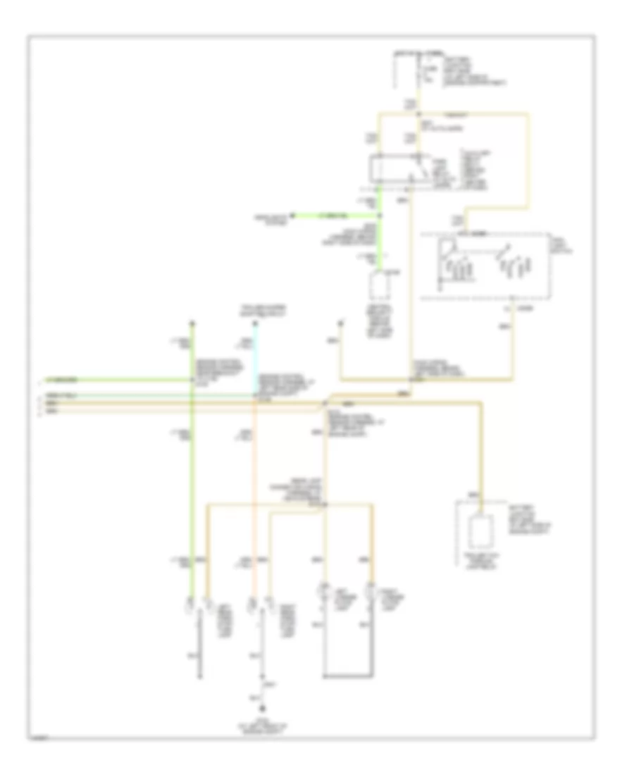
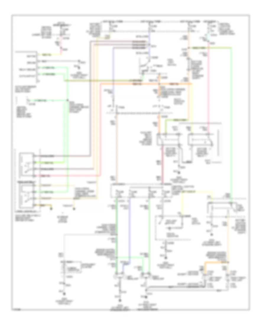
AIR CONDITIONING
Heater Wiring Diagram for Ford Pickup Heritage F150 2004
 https://portal-diagnostov.com/license.html
Automotive Electricians Portal FZCO
Automotive Electricians Portal FZCO
https://portal-diagnostov.com/license.html
https://portal-diagnostov.com/license.html
Automotive Electricians Portal FZCO
Automotive Electricians Portal FZCO
List of elements for Heater Wiring Diagram for Ford Pickup Heritage F150 2004:
- (main wiring harness, near glove box) s200
- +/-
- Auxiliary relay box 4 (behind center of dash)
- Auxiliary relay box 4)
- Battery junction box box (bjb) (in left side of engine compt)
- Blower motor relay
- Blower motor resistor (near blower motor)
- Blower motor switch
- C270a
- C270b
- C294a
- C294b
- C294c
- C294d
- Central junction box box (cjb) (under left side of dash)
- Command
- Crtl pot gnd
- Crtl pot vs
- Defrost
- Floor
- Floor/ vent
- Front blower motor (behind right side of dash)
- Function selector assembly
- Fuse 10a
- Fuse 15a
- Fuse 40a
- G200 (in right front footwell)
- Gnd
- High
- Hot at all times
- Hot in run
- Illumination
- Interior lights system
- Low
- Max
- Med hi
- Med low
- Mix
- Normal
- Off
- S125 (behind right side of dash)
- S202 (main wiring harness, near breakout to auxiliary relay box 4)
- S203 (main wiring harness, behind right side of dash)
- S222 (main wiring harness, behind left side of dash)
- Temperature blend door actuator (behind center of dash)
- Temperature control potentiometer
- Vent
- Vpwr
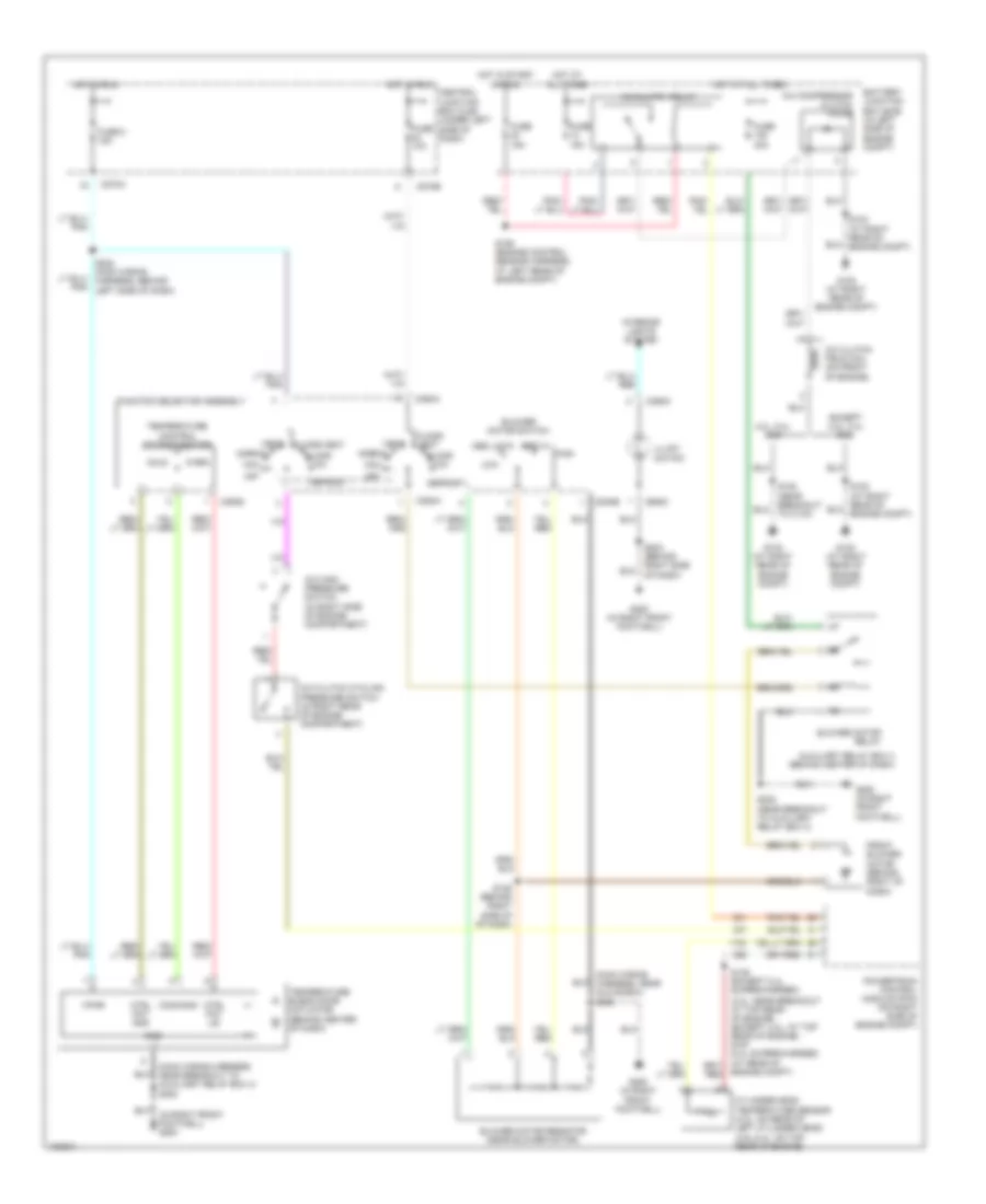
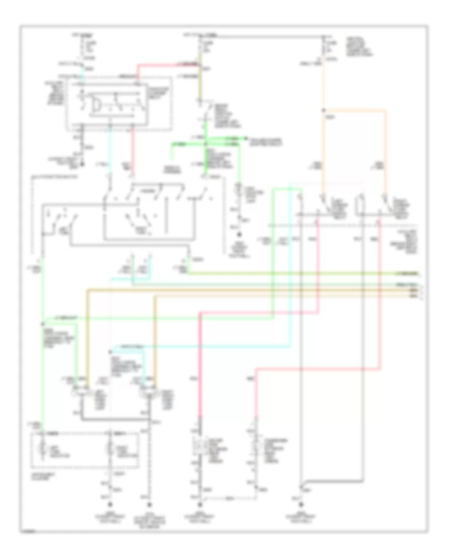
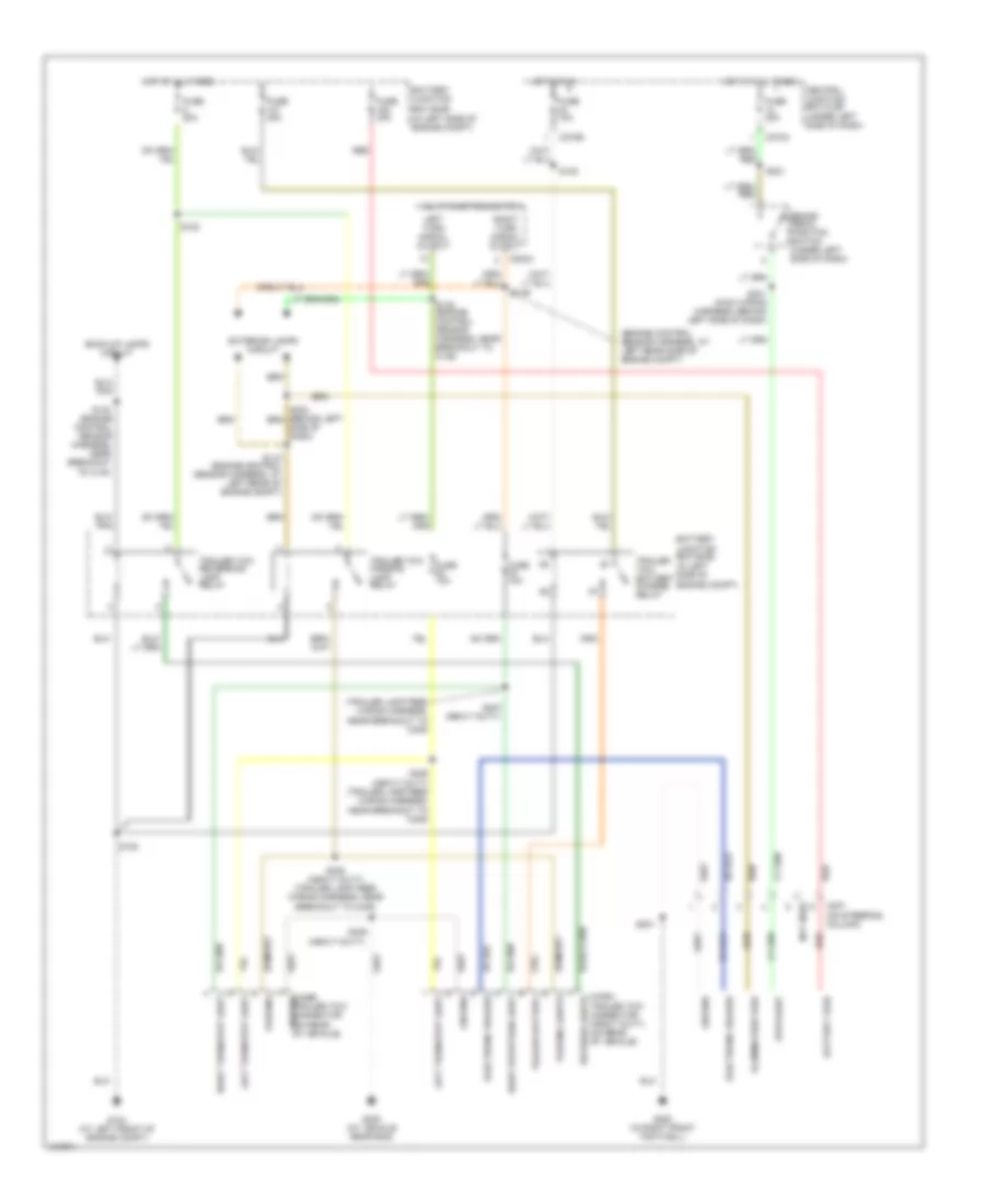
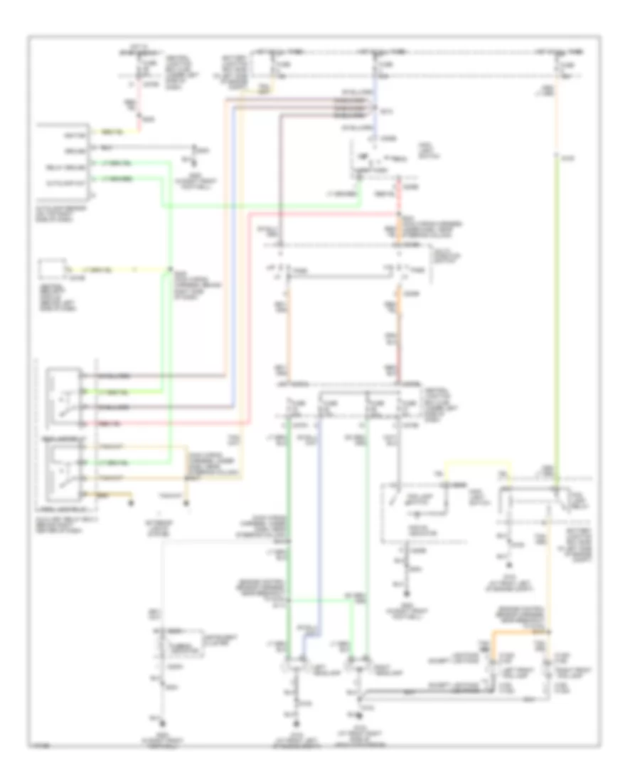
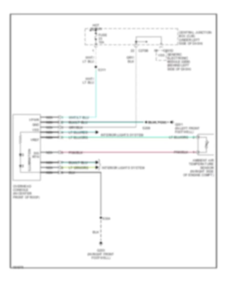
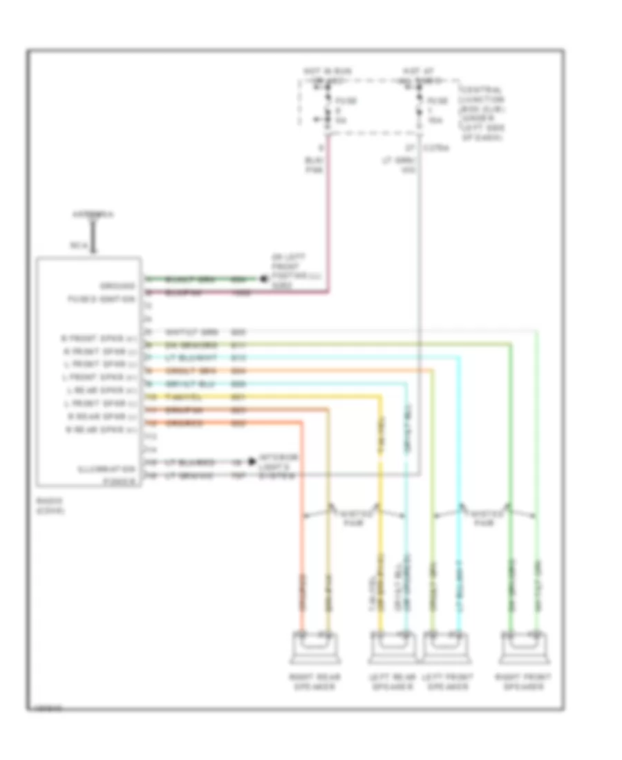
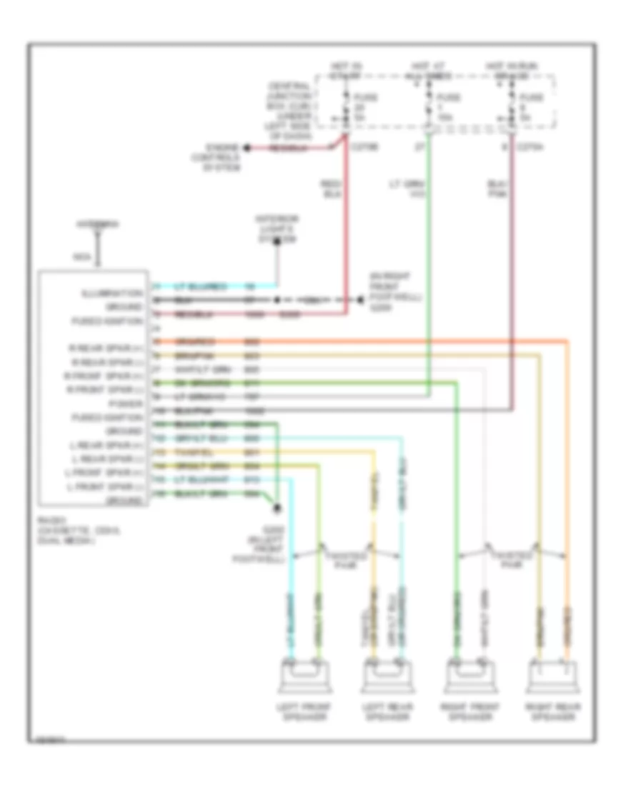
Manual A/C Wiring Diagram for Ford Pickup Heritage F150 2004
List of elements for Manual A/C Wiring Diagram for Ford Pickup Heritage F150 2004:
- (in right front footwell) g200
- (main wiring harness, near breakout to auxiliary relay box 4) s202
- (main wiring harness, near glove box) s200
- +/-
- 4.2l, 5.4l cng
- A/c clutch cycling pressure switch (in right rear of engine compartment)
- A/c clutch field coil (on front of engine)
- A/c clutch relay
- A/c compressor clutch diode
- A/c high pressure switch (in right side of engine compartment)
- Auxiliary relay box 4 (behind center of dash)
- Battery junction box (bjb) (in left side of engine compt)
- Blower motor relay
- Blower motor resistor (near blower motor)
- Blower motor switch
- C270a
- C270b
- C294a
- C294b
- C294c
- C294d
- Central junction box (cjb) (under left side of dash)
- Cold
- Command
- Ctrl pot gnd
- Ctrl pot us
- Cylinder-head temperature sensor (4.2l: on rear of left cylinder head) (4.6l,5.4l: on top rear of engine)
- Defrost
- Engine compt)
- Except 4.2l, 5.4l cng
- Floor
- Floor/ vent
- Floor/vent
- Front blower motor (behind right of dash)
- Function selector assembly
- Fuse 10a
- Fuse 15a
- Fuse 40a
- Fuse 5 15a
- G102 (at right rear of engine compt)
- G200 (in right front footwell)
- Gnd
- High
- Hot at all times
- Hot in run
- Hot in start or run
- Illumi- nation
- Interior lights system
- Low
- Max
- Med hi
- Med low
- Mix
- Normal
- Off
- Powertrain control module (pcm) (on right side of engine compt)
- S102 (at right rear of engine compt)
- S125 (behind right side of of dash)
- S135 (except 5.4l supercharged)
- S153 (near breakout to c133)
- S155 (engine control sensor harness, at left rear of engine compt)
- S202 (near breakout to auxiliary relay box 4)
- S203 (behind right side of dash)
- S222 (main wiring harness, behind pnk left side of dash)
- Temperature blend door actuator (behind center of dash)
- Temperature control potentiometer
- Vent
- Vpwr
- Warm
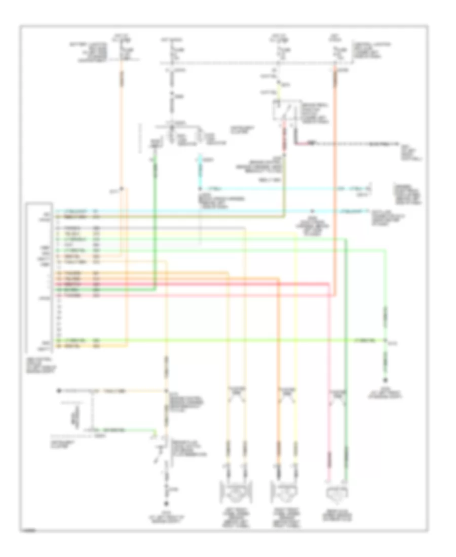
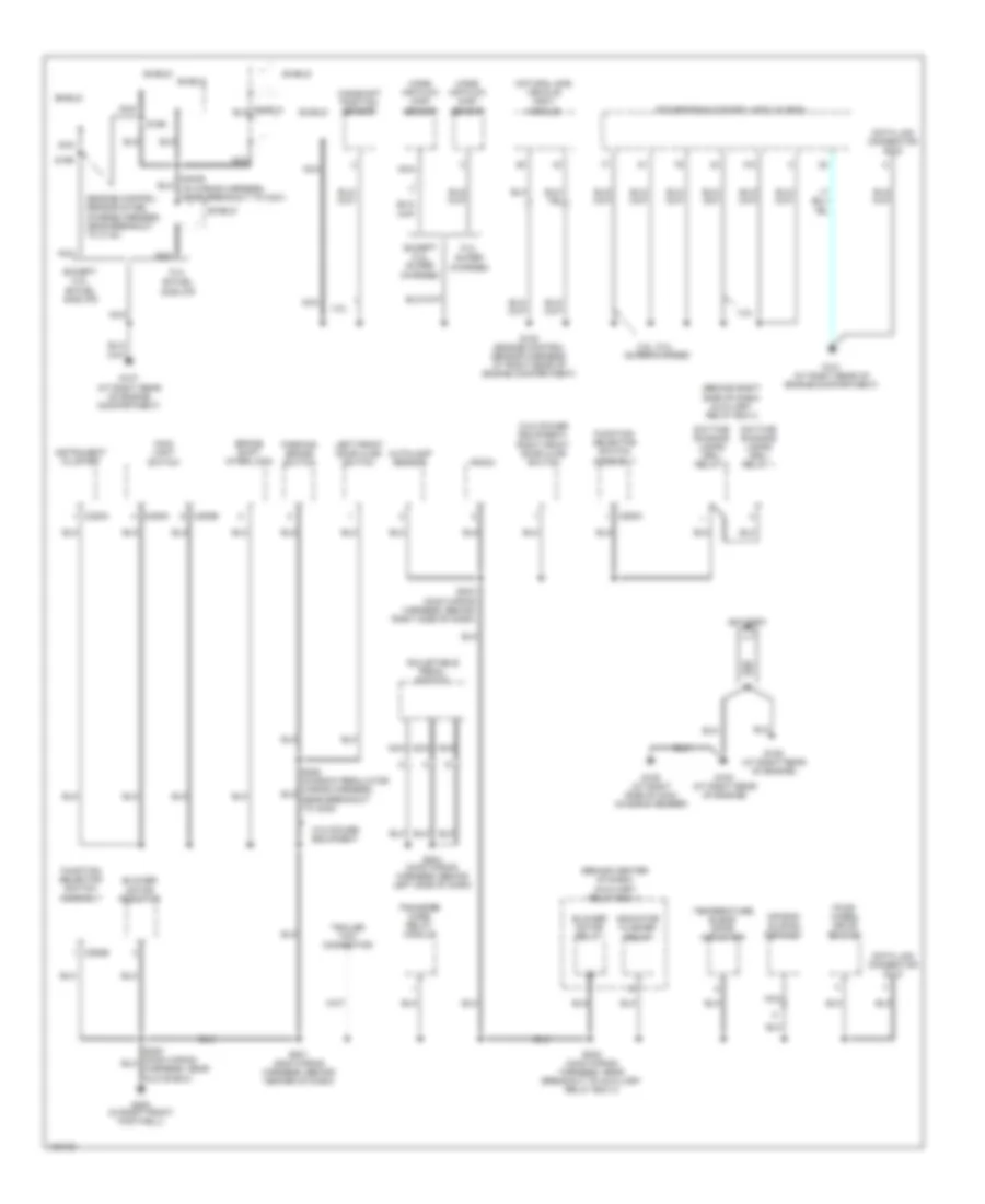
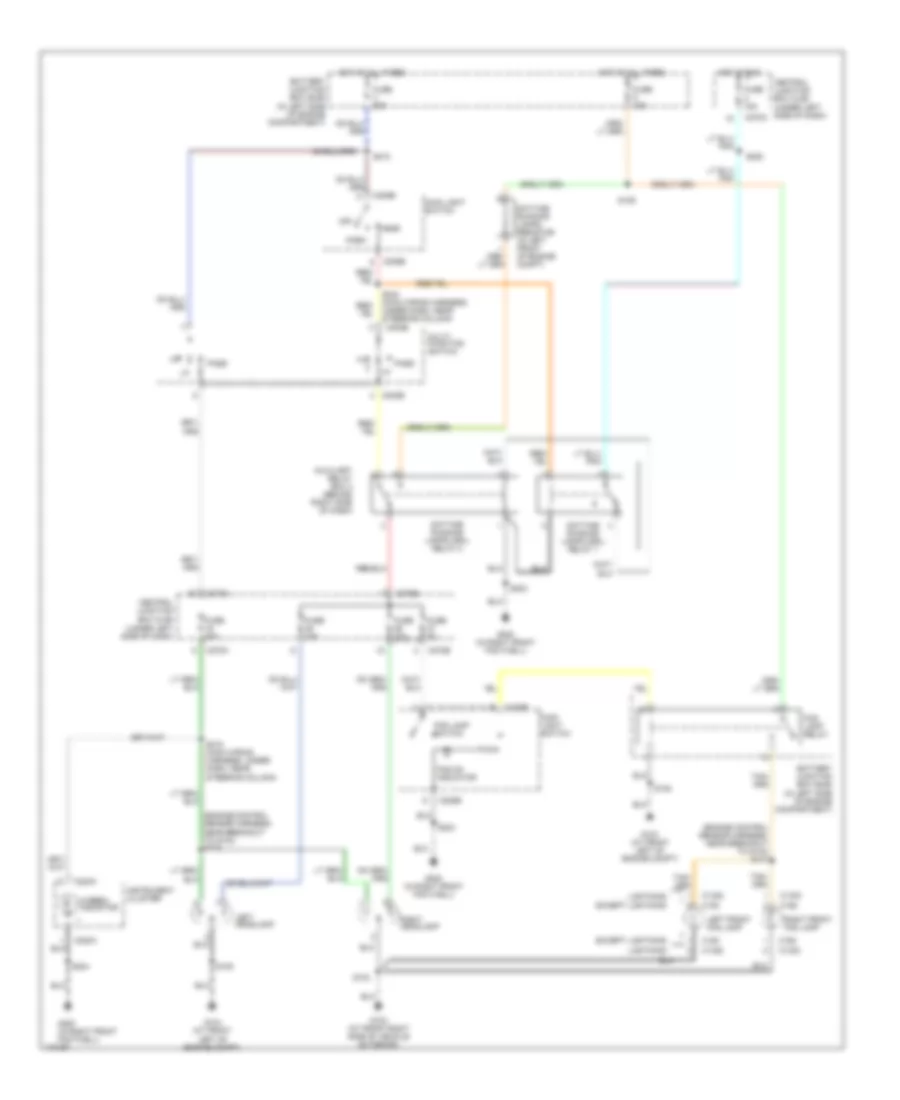
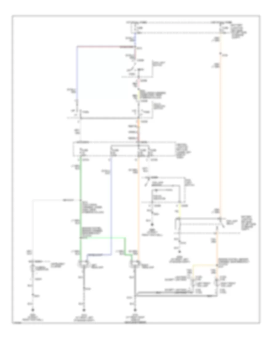
ANTI-LOCK BRAKES
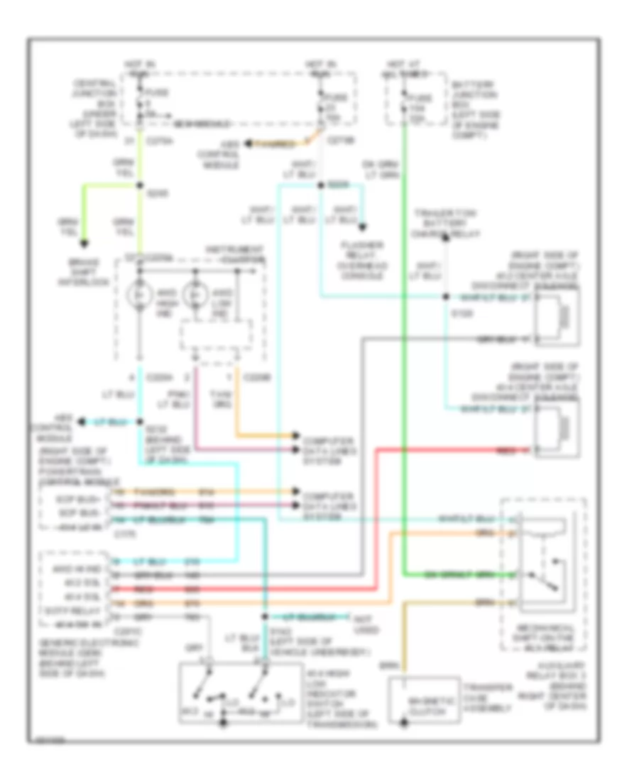
Anti-lock Brakes Wiring Diagram for Ford Pickup Heritage F150 2004
List of elements for Anti-lock Brakes Wiring Diagram for Ford Pickup Heritage F150 2004:
- 4wd high indicator
- Abs control module (in left side of engine compt)
- Anti- lock indicator
- Battery junction box (bjb) (in left side of engine compartment)
- Bias ckt
- Brake fluid level switch (on brake fluid reservoir)
- Brake pedal position switch (under left side of dash)
- C201c
- C220a
- C270a
- C270b
- Central junction box (cjb) (under left side of dash)
- Data link connector (dlc) (near center of dash)
- Fuse 10a
- Fuse 50a
- Fuse 5a
- G104 (at left front of engine compt)
- G106 (at left front of engine compt)
- G201 (in left front footwell)
- Generic electronic module (gem) (behind left side of dash)
- Gnd
- Hot at all times
- Hot in run
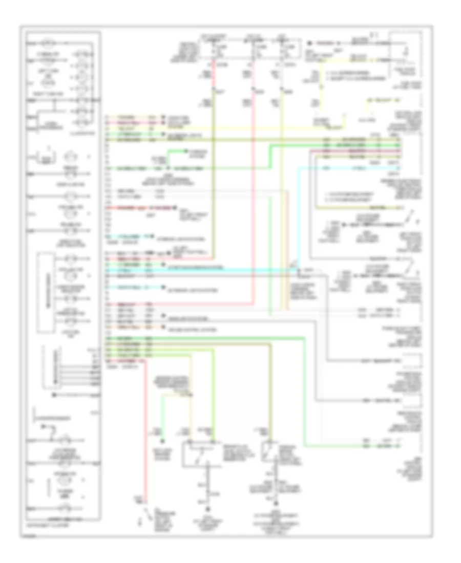
- Instrument cluster
- Iso
- Left front wheel speed sensor (behind left front wheel)
- Nca
- Processor micro-
- Rear axle speed sensor (on rear axle)
- Red/pnk
- Right front wheel speed sensor (behind right front wheel)
- S106
- S160 (engine control sensor harness, near breakout to c192)
- S170 (engine control sensor harness, near breakout to c140)
- S171
- S172
- S208
- S229 (main wiring harness, behind left side of dash)
- S265
- S274
- Tan/red
- Twisted pair
- Vbatt
- Vpwr
- Vref
ANTI-THEFT
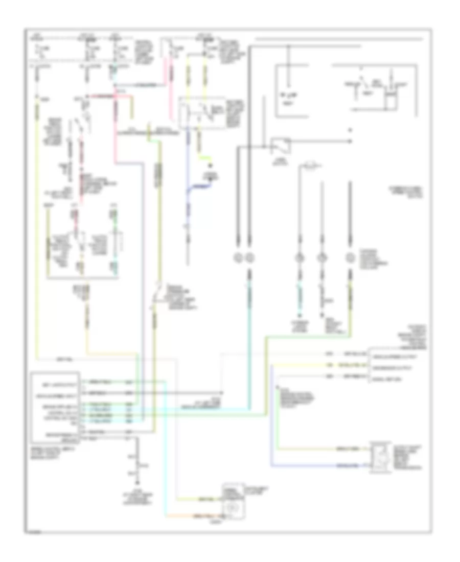
Forced Entry Wiring Diagram for Ford Pickup Heritage F150 2004
List of elements for Forced Entry Wiring Diagram for Ford Pickup Heritage F150 2004:
- (behind left side of dash) s601
- (in right front footwell)
- (in right front footwell) g203
- (near center of dash) data link connector (dlc)
- (near steering column) s234
- 1/2
- 3/4
- 5/6
- 7/8
- 9/0
- Ajar out
- Battery
- Battery junction box (bjb) (in left side of engine compt)
- Bpp sw in
- Brake pedal position switch (under left side of dash)
- C201a
- C201b
- C270b
- C274a
- C274b
- Central junction box (cjb) (under left side of dash)
- Central security module (behind left side of dash)
- Door ajar
- Doors lock
- Doors unlock
- Dr ajar sw
- Driver side door lock switch
- Exterior lights system
- Fuse 15a
- Fuse 5a
- G201 (in left front footwell)
- G203
- G203 (in right front footwell)
- Generic electronic module (gem) (behind left side of dash)
- Ground
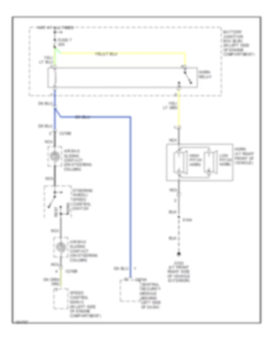
- Horn
- Horns system
- Hot at all times
- Hot in start or run
- Illum entry
- Illum in
- Interior lights system
- Iso
- Key pad common
- Key pad switch assembly
- Keypad illum
- Left front door ajar switch (in left front door)
- Left front door lock actuator (in left front door)
- Lf out
- Lft
- Lock
- Lock in/out
- Nca
- Passenger side door lock switch
- Red
- Relay ctrl
- Reverse
- Right front door ajar switch (in right front door)
- Right front door lock actuator (in right front door)
- S208
- S225
- S229 (main wiring harness, behind left side of dash)
- S235 (body main wiring harness, near steering column)
- S274
- S297 (main wiring harness, behind left side of dash)
- S500
- S501
- S600
- Unlk
- Unlock in/out
- Vpwr
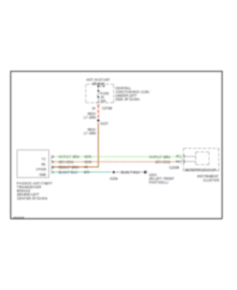
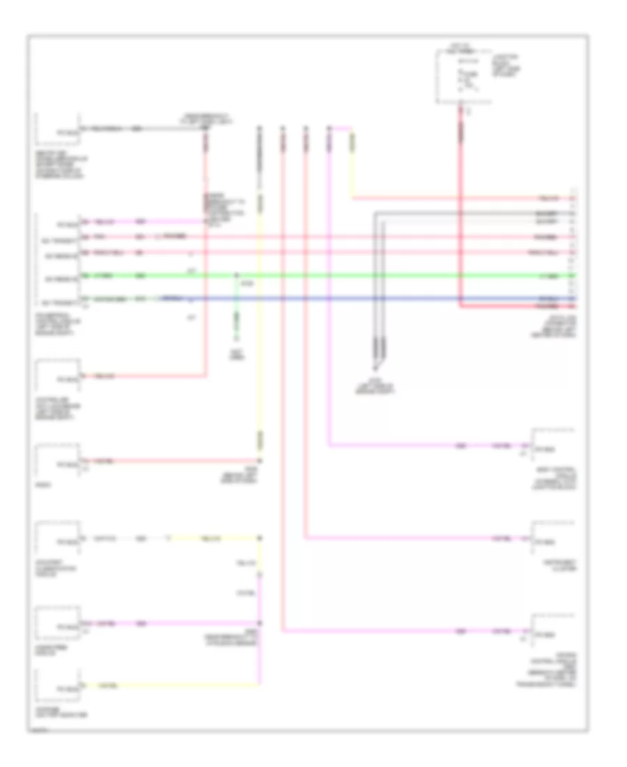
Passive Anti-theft Wiring Diagram for Ford Pickup Heritage F150 2004
List of elements for Passive Anti-theft Wiring Diagram for Ford Pickup Heritage F150 2004:
- C220b
- C270b
- Central junction box (cjb) (under left side of dash)
- Fuse 30a
- G201 (in left front footwell)
- Gnd
- Hot in start or run
- Instrument cluster
- Microprocessor
- Passive anti-theft transceiver module (behind left center of dash)
- S208
- S237
- Vpwr
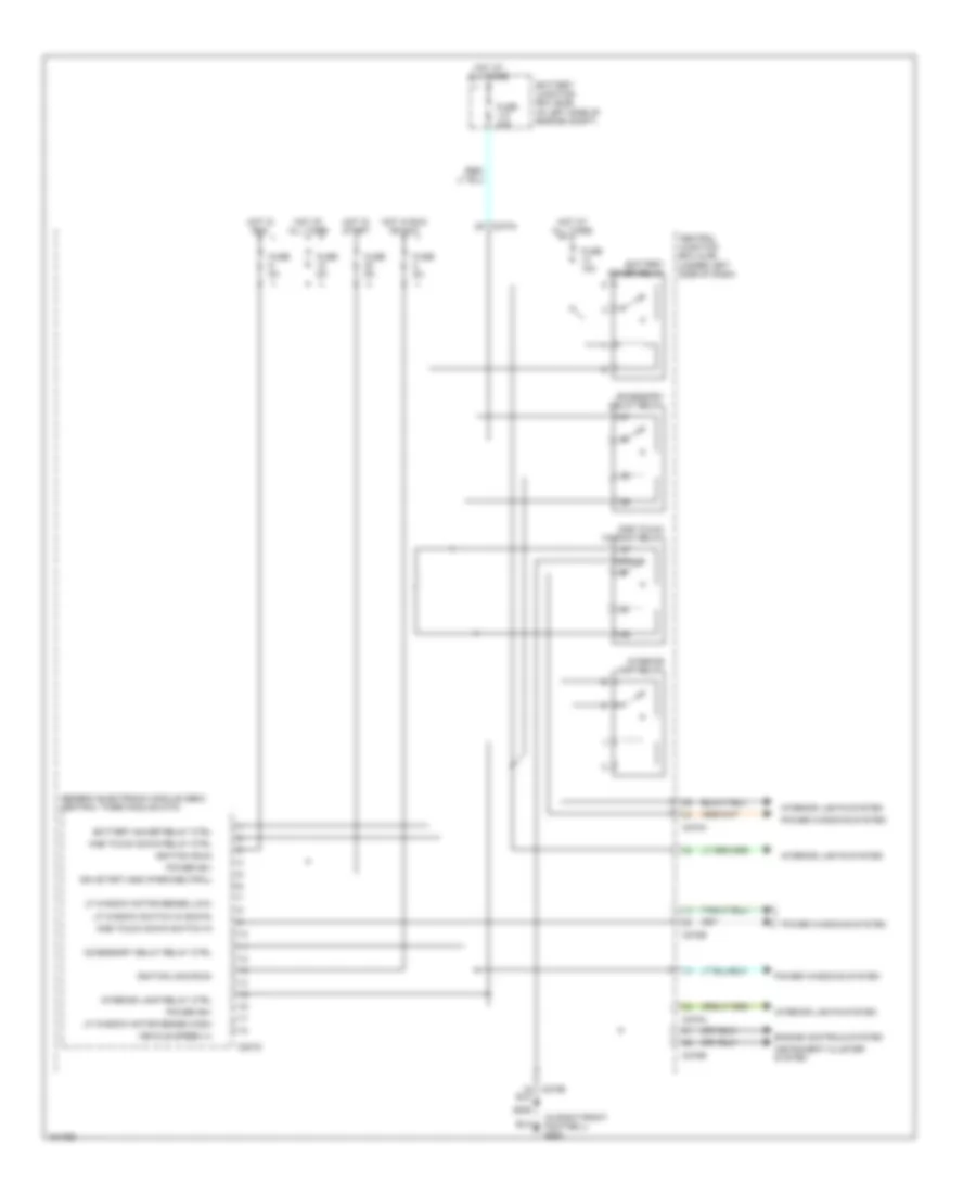
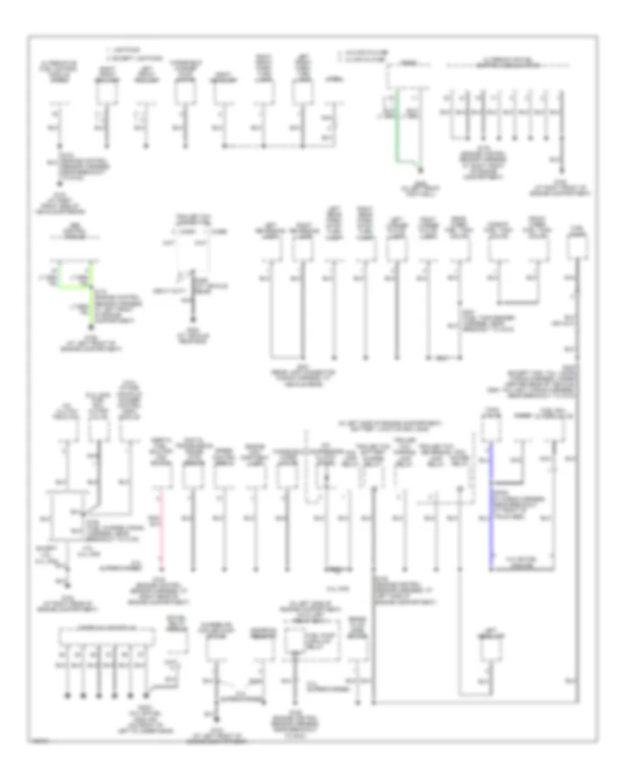
BODY CONTROL MODULES
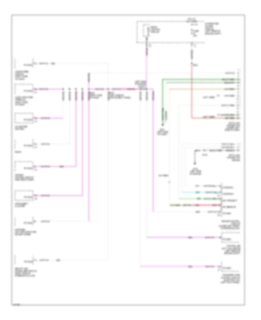
Body Control Modules Wiring Diagram (1 of 2) for Ford Pickup Heritage F150 2004
List of elements for Body Control Modules Wiring Diagram (1 of 2) for Ford Pickup Heritage F150 2004:
- (in right front footwell) g203
- 87a
- Accessory delay relay
- Accessory delay relay ctrl
- Battery junction box (bjb) (in left side of engine compt)
- Battery saver relay
- Battery saver relay ctrl
- C201d
- C270a
- C270b
- Central junction box (cjb) (under left side of dash)
- Engine controls system
- Fuse 15a
- Fuse 30a
- Fuse 5a
- Generic electronic module (gem)/ central timer module (ctm)
- Hot at all times
- Hot in run
- Hot in run or acc
- Hot in start
- Ign (start) gnd (park/neutral)
- Ignition (acc/run)
- Ignition (run)
- Instrument cluster system
- Interior lamp relay
- Interior lamp relay ctrl
- Interior lights system
- Lf window motor sense (high)
- Lf window motor sense (low)
- Lf window switch in (down)
- One touch down relay ctrl
- One touch down switch in
- One touch window relay
- Power (b+)
- Power windows system
- S205
- Vehicle speed (+)
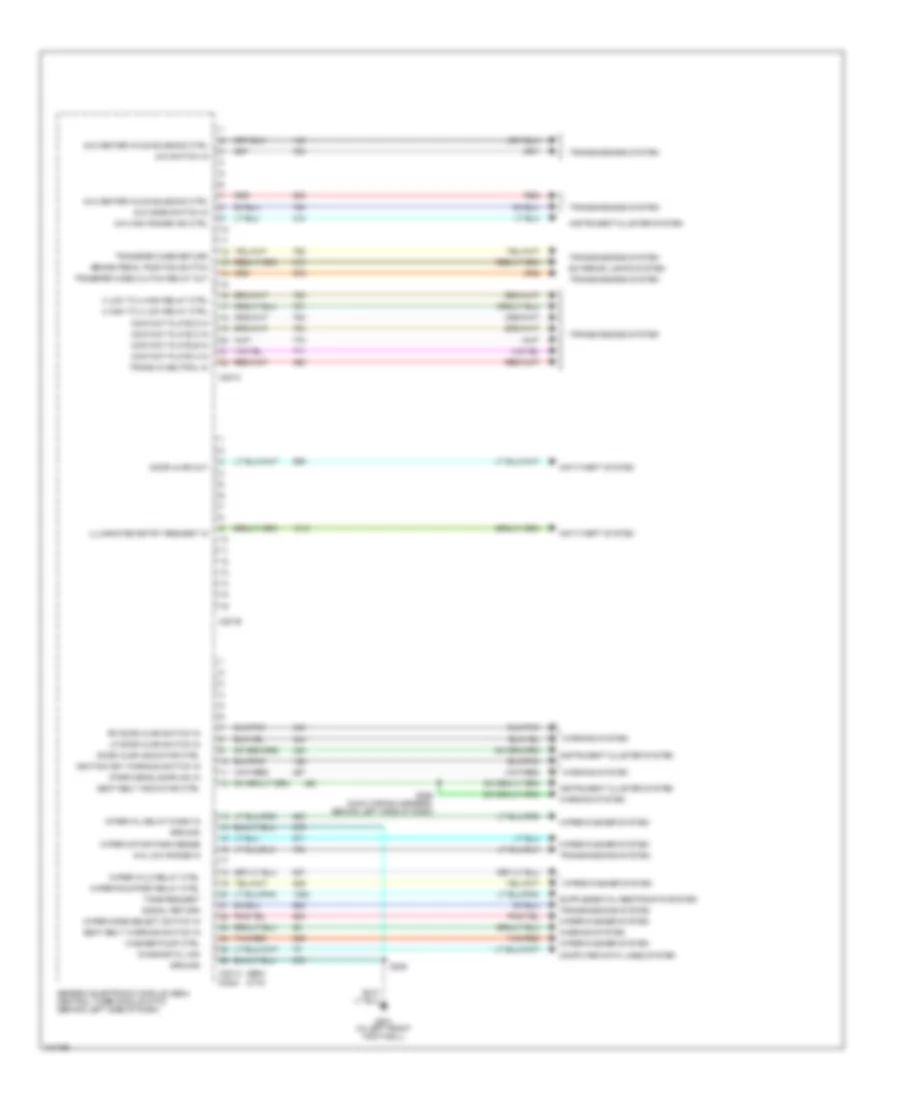
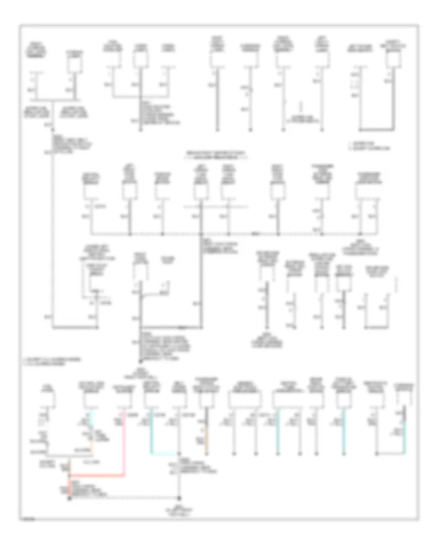
Body Control Modules Wiring Diagram (2 of 2) for Ford Pickup Heritage F150 2004
List of elements for Body Control Modules Wiring Diagram (2 of 2) for Ford Pickup Heritage F150 2004:
- (ctm)
- (gem)
- (park/headlamps on) in
- 4 high to 4 low relay ctrl
- 4 low to 4 high relay ctrl
- 4x2 center axle solenoid ctrl
- 4x4 center axle solenoid ctrl
- 4x4 high range ind ctrl
- 4x4 low range in
- 4x4 mode switch in
- 4x4 switch in
- Anti-theft system
- Brake pedal position switch
- C201a
- C201b
- C201c
- C2224
- Computer data lines system
- Contact plate a in
- Contact plate b in
- Contact plate c in
- Contact plate d in
- Diagnostic link
- Door ajar indicator ctrl
- Door ajar out
- Exterior lights system
- G201 (in left front footwell)
- Generic electronic module (gem)/ central timer module (ctm) (behind left side of dash)
- Ground
- Ignition key warning switch in
- Illuminated entry request in
- Instrument cluster system
- Interval delay/wash in
- Lf door ajar switch in
- Red
- Rf door ajar switch in
- S208
- S268 (main wiring harness, behind left side of dash)
- Seat belt indicator ctrl
- Seat belt warning switch in
- Signal return
- Tan/red
- Tone request
- Trans in neutral in
- Transfer case clutch relay out
- Transfer case return
- Transmissions system
- Warning system
- Washer pump ctrl
- Wiper hi/lo relay ctrl
- Wiper mode select switch in
- Wiper motor park sense
- Wiper run/park relay ctrl
- Wiper/washer system
COMPUTER DATA LINES
4.2L
4.2L, Computer Data Lines Wiring Diagram for Ford Pickup Heritage F150 2004
List of elements for 4.2L, Computer Data Lines Wiring Diagram for Ford Pickup Heritage F150 2004:
- (left side of engine compt) s232
- (not used)
- (or pnk)
- A/c-heater control
- Air bag control module (center of dash)
- Audio amplifier (premium) (right side of dash)
- Ccd bus(+)
- Ccd bus(-)
- Compass/ mini-trip computer (except base)
- Controller anti-lock brake (left rear of engine compt)
- D20
- D21
- D25
- D71
- D72
- Data link connector (under left side of dash)
- Data link connector engine
- Engine control module (lower left front of engine block)
- Front control module
- Fuse 20a
- G120 (left side of engine)
- G201 (left side of dash)
- Hands free module (right side of dash)
- Hot at all times
- Instrument cluster
- Integrated power module (left rear of engine compt)
- Pci bus
- Pnk
- Radio
- S176
- S204
- Sci receive
- Sci transmit
- Sentry key immobilizer module (right side of steering column)
- Transfer case control module (electric 4x4) (left kick panel)
4.6L
4.6L, Computer Data Lines Wiring Diagram for Ford Pickup Heritage F150 2004
List of elements for 4.6L, Computer Data Lines Wiring Diagram for Ford Pickup Heritage F150 2004:
- (left side of engine compt) s232
- (not used)
- (or pnk)
- A/c-heater control
- Air bag control module (center of dash)
- Audio amplifier (premium) (right side of dash)
- Ccd bus(+)
- Ccd bus(-)
- Compass/ mini-trip computer (except base)
- Controller anti-lock brake (left rear of engine compt)
- D20
- D21
- D25
- D71
- D72
- Data link connector (under left side of dash)
- Data link connector engine
- Engine control module (lower left front of engine block)
- Front control module
- Fuse 20a
- G120 (left side of engine)
- G201 (left side of dash)
- Hands free module (right side of dash)
- Hot at all times
- Instrument cluster
- Integrated power module (left rear of engine compt)
- Pci bus
- Pnk
- Radio
- S176
- S204
- Sci receive
- Sci transmit
- Sentry key immobilizer module (right side of steering column)
- Transfer case control module (electric 4x4) (left kick panel)
5.4L
5.4L, Computer Data Lines Wiring Diagram for Ford Pickup Heritage F150 2004
List of elements for 5.4L, Computer Data Lines Wiring Diagram for Ford Pickup Heritage F150 2004:
- (left side of engine compt) s232
- (not used)
- (or pnk)
- A/c-heater control
- Air bag control module (center of dash)
- Audio amplifier (premium) (right side of dash)
- Ccd bus(+)
- Ccd bus(-)
- Compass/ mini-trip computer (except base)
- Controller anti-lock brake (left rear of engine compt)
- D20
- D21
- D25
- D71
- D72
- Data link connector (under left side of dash)
- Data link connector engine
- Engine control module (lower left front of engine block)
- Front control module
- Fuse 20a
- G120 (left side of engine)
- G201 (left side of dash)
- Hands free module (right side of dash)
- Hot at all times
- Instrument cluster
- Integrated power module (left rear of engine compt)
- Pci bus
- Pnk
- Radio
- S176
- S204
- Sci receive
- Sci transmit
- Sentry key immobilizer module (right side of steering column)
- Transfer case control module (electric 4x4) (left kick panel)
5.4L BI-FUEL GAS/CNG
5.4L Bi-Fuel Gas/CNG, Computer Data Lines Wiring Diagram for Ford Pickup Heritage F150 2004
List of elements for 5.4L Bi-Fuel Gas/CNG, Computer Data Lines Wiring Diagram for Ford Pickup Heritage F150 2004:
- (near breakout to left dash light) s201
- (not used)
- A/t
- A14
- Air bag control module (orc) (beneath center of dash, on transmission tunnel)
- Body control module (integral with junction block)
- Compass mini-trip computer
- Controller anti-lock brake (left side of engine compt)
- D15
- D20
- D21
- D25
- Data link connector (behind left center of dash)
- Fuse 10a
- G100 (left side of engine compt)
- Hands free module
- Hot at all times
- Instrument cluster
- Junction block (left side of dash)
- Occupant classification module
- Pci bus
- Pnk
- Pnk/red
- Powertrain control module (left side of engine compt)
- Radio
- S126
- S336 (behind left side of dash)
- S393 (near breakout to intrusion sensor)
- Sci receive
- Sci transmit
- Sentry key immobilizer module (except base) (on right side of steering column)
5.4L BI-FUEL GAS/LPG
5.4L Bi-Fuel Gas/LPG, Computer Data Lines Wiring Diagram for Ford Pickup Heritage F150 2004
List of elements for 5.4L Bi-Fuel Gas/LPG, Computer Data Lines Wiring Diagram for Ford Pickup Heritage F150 2004:
- (near breakout to left dash light) s201
- (not used)
- A/t
- A14
- Air bag control module (orc) (beneath center of dash, on transmission tunnel)
- Body control module (integral with junction block)
- Compass mini-trip computer
- Controller anti-lock brake (left side of engine compt)
- D15
- D20
- D21
- D25
- Data link connector (behind left center of dash)
- Fuse 10a
- G100 (left side of engine compt)
- Hands free module
- Hot at all times
- Instrument cluster
- Junction block (left side of dash)
- Occupant classification module
- Pci bus
- Pnk
- Pnk/red
- Powertrain control module (left side of engine compt)
- Radio
- S126
- S336 (behind left side of dash)
- S393 (near breakout to intrusion sensor)
- Sci receive
- Sci transmit
- Sentry key immobilizer module (except base) (on right side of steering column)
5.4L CNG
5.4L CNG, Computer Data Lines Wiring Diagram for Ford Pickup Heritage F150 2004
List of elements for 5.4L CNG, Computer Data Lines Wiring Diagram for Ford Pickup Heritage F150 2004:
- (left side of engine compt) s232
- (not used)
- (or pnk)
- A/c-heater control
- Air bag control module (center of dash)
- Audio amplifier (premium) (right side of dash)
- Ccd bus(+)
- Ccd bus(-)
- Compass/ mini-trip computer (except base)
- Controller anti-lock brake (left rear of engine compt)
- D20
- D21
- D25
- D71
- D72
- Data link connector (under left side of dash)
- Data link connector engine
- Engine control module (lower left front of engine block)
- Front control module
- Fuse 20a
- G120 (left side of engine)
- G201 (left side of dash)
- Hands free module (right side of dash)
- Hot at all times
- Instrument cluster
- Integrated power module (left rear of engine compt)
- Pci bus
- Pnk
- Radio
- S176
- S204
- Sci receive
- Sci transmit
- Sentry key immobilizer module (right side of steering column)
- Transfer case control module (electric 4x4) (left kick panel)
5.4L SUPERCHARGED
5.4L Supercharged, Computer Data Lines Wiring Diagram for Ford Pickup Heritage F150 2004
List of elements for 5.4L Supercharged, Computer Data Lines Wiring Diagram for Ford Pickup Heritage F150 2004:
- (left side of engine compt) s232
- (not used)
- (or pnk)
- A/c-heater control
- Air bag control module (center of dash)
- Audio amplifier (premium) (right side of dash)
- Ccd bus(+)
- Ccd bus(-)
- Compass/ mini-trip computer (except base)
- Controller anti-lock brake (left rear of engine compt)
- D20
- D21
- D25
- D71
- D72
- Data link connector (under left side of dash)
- Data link connector engine
- Engine control module (lower left front of engine block)
- Front control module
- Fuse 20a
- G120 (left side of engine)
- G201 (left side of dash)
- Hands free module (right side of dash)
- Hot at all times
- Instrument cluster
- Integrated power module (left rear of engine compt)
- Pci bus
- Pnk
- Radio
- S176
- S204
- Sci receive
- Sci transmit
- Sentry key immobilizer module (right side of steering column)
- Transfer case control module (electric 4x4) (left kick panel)
CRUISE CONTROL
Cruise Control Wiring Diagram for Ford Pickup Heritage F150 2004
List of elements for Cruise Control Wiring Diagram for Ford Pickup Heritage F150 2004:
- (main wiring harness, behind left side of dash)
- (on right side of engine compt)
- 5.4l supercharged
- A/t
- Accel
- Air bag sliding contact (on steering column)
- Battery junction box (bjb) (in left side of engine compt)
- Brake pedal position switch (under left side of dash)
- Brake press in
- Brake pressure switch (in left rear corner of engine compt)
- C220a
- C270a
- C270b
- Central junction box (cjb) (under left side of dash)
- Clutch pedal position switch (on clutch pedal arm)
- Clutch triple function switch jumper
- Coast
- Control sw gnd
- Control sw in
- Esof
- Exc 5.4l supercharged
- Fuse 15a
- Fuse 20a
- Fuse 2a
- Fuse 5a
- G102 (at right rear of engine compartment)
- G200 (in right front footwell)
- G201 (in left front footwell)
- Ground
- Horn relay
- Horn switch
- Horns system
- Hot at all times
- Hot in run
- Ign
- Instrument cluster
- Interior lights system
- M/t
- Nca
- Off
- Oss sensor output
- Output shaft speed (oss) sensor (on left side of transmission)
- Powertrain control module (pcm)
- Rest
- Resume
- S102
- S112
- S138 (engine control sensor harness, near breakout to g101)
- S143 (at left side vehicle underbody)
- S208
- S265
- S274
- Set lamp output
- Set/
- Signal return
- Speed control indicator
- Speed control servo (in left side of engine compt)
- Steering wheel/ speed control switch
- Vehicle speed input
- Vehicle speed output
ENGINE PERFORMANCE
4.2L
4.2L, Engine Performance Wiring Diagram (1 of 4) for Ford Pickup Heritage F150 2004
List of elements for 4.2L, Engine Performance Wiring Diagram (1 of 4) for Ford Pickup Heritage F150 2004:
- (left front of engine compartment)
- (right rear of engine compt)
- (right rear of engine compt) g101
- 4x4 low sw
- 820 ohms
- A/c system
- Accs
- B nca
- Battery junction box (bjb) (left side of engine compt)
- C243
- C270b
- Case gnd
- Central junction box (cjb) (under left side of dash)
- Ckp(+)
- Ckp(-)
- Data link (+)
- Data link (-)
- Data link connector (dlc) (partial) (under center of dash)
- Digital transmission range (dtr) sensor (left side of transmission)
- Dlc
- Evr ctrl
- Fuel pump mon
- Fuse 30a
- Fuse 5a
- G102 (right rear of engine compt)
- G104
- G107
- Ho2s (12)
- Hot at all times
- Hot in run or start
- Iat
- Ign coil 1
- Ign coil 2
- Ignition coil (top right side of eng)
- Ignition transformer capacitor 1 (top right side of eng)
- Imrc
- Instrument cluster system
- Intake manifold runner control (imrc) module (top rear of engine)
- Ks sensor
- Maf
- Nca
- O/d off
- Pcm power diode
- Pcm power relay
- Powertrain control module (pcm) (right side of engine compt)
- Pwr gnd
- R n
- S100
- S106
- S116
- S117 (near breakout to c133)
- S153
- S225
- Shift sol a
- Shift sol b
- Tcs
- Tft
- To dtr sensor (diagram 4 of 4)
- Tr1
- Tr2
- Tr4
- Transmission control indicator lamp
- Transmission control switch (a/t)
- Transmission system
4.2L, Engine Performance Wiring Diagram (2 of 4) for Ford Pickup Heritage F150 2004
List of elements for 4.2L, Engine Performance Wiring Diagram (2 of 4) for Ford Pickup Heritage F150 2004:
- (left side of vehicle underbody) s127
- (near breakout to c192)
- (near breakout to g101)
- (right rear of engine compt) s137
- (under left side of dash) central junction box (cjb)
- Battery junction box (bjb) (left side of engine compt)
- C201d
- C220a
- Check fuel cap indicator
- Crankshaft position sensor (lower front of engine)
- Crankshaft position sensor shield
- Differential pressure feedback egr (dpfe) sensor (right side of engine)
- Fuel pump relay
- Fuel tank pressure transducer sensor (at fuel tank)
- Fuse 15a
- Fuse 20a
- G107 (right rear of engine compt)
- Generic electronic module/ central timer module
- Hot at all times
- Instrument cluster
- Intake air temperature (iat) sensor (on air intake)
- Nca
- Pnk
- Red
- Red/pnk
- S100
- S135 (near breakout at top rear of eng)
- S136 (rear of eng compt)
- S138
- S139
- Throttle position sensor (tps) (on throttle body)
- Transfer case speed sensor (at left side of transmission)
- Vss input
4.2L, Engine Performance Wiring Diagram (3 of 4) for Ford Pickup Heritage F150 2004
List of elements for 4.2L, Engine Performance Wiring Diagram (3 of 4) for Ford Pickup Heritage F150 2004:
- (at fuel tank) fuel pump
- (behind right kick panel) inertia fuel shutoff (ifs) switch
- (left front of engine compt)
- (left rear of engine compt)
- (near breakout to c110)
- (near breakout to c133)
- 4r70w transmission
- Egr vacuum regulator solenoid (right side of engine)
- Electronic pressure control solenoid
- Evap canister purge
- Fuel injectors
- G104
- Idle air control (iac) valve (on left side of intake manifold)
- Instrument cluster system
- Nca
- Output shaft speed (oss) sensor (left side of transmission)
- Pnk
- Red
- Red/pnk
- S129
- S131 (top front of engine)
- S140
- S141 (near breakout to c110)
- S154
- S155
- S400
- Shift solenoids
- Ssa
- Ssb
- Tan
- Torque converter clutch solenoid
- Transmission fluid temperature sensor
- Valve (left rear corner of engine compt)
4.2L, Engine Performance Wiring Diagram (4 of 4) for Ford Pickup Heritage F150 2004
List of elements for 4.2L, Engine Performance Wiring Diagram (4 of 4) for Ford Pickup Heritage F150 2004:
- (in left side of engine compt) speed control servo
- (left front footwell)
- (left side of vehicle underbody)
- (near fuel tank) evaporative emission (evap) canister vent valve
- (on left side of engine compartment)
- (rear of left cyl head) cylinder- head temperature sensor
- (top left rear of engine) knock sensor
- (under left side of dash) brake pedal position switch
- 5v ref volt
- A/c clutch relay
- A/t
- Battery junction box (bjb)
- Bpp sw
- C270a
- C270b
- Cam pos in
- Camshaft position sensor (on front of engine)
- Canister vent
- Central junction box (cjb) (under left side of dash)
- Cyl head temp
- Digital transmission range (dtr) sensor (left side of transmission)
- Dpfe sens
- Epc sol
- From dtr sensor (diagram 1 of 4)
- Fuel inj 1
- Fuel inj 2
- Fuel inj 3
- Fuel inj 4
- Fuel inj 5
- Fuel inj 6
- Fuel pump ctrl
- Fuel tank press
- Fuse 5a
- G107 (right rear of engine compt)
- G107 (right rear of engine compt)
- G201
- Heated oxygen sensor (ho2s) 11 (on engine exhaust pipe)
- Heated oxygen sensor (ho2s) 12 (on engine exhaust pipe)
- Heated oxygen sensor (ho2s) 21 (on engine exhaust pipe)
- Heated oxygen sensor (ho2s) 22 (on engine exhaust pipe)
- Heater ctrl
- Hot at all times
- Hot in start
- Iac sol
- Ign coil 3
- Ind lp ctrl
- Kap b(+)
- Knock sensor
- Lf ho2s
- Lf ho2s sig (21)
- Lr ho2s
- Lr ho2s sig (22)
- M/t
- Maf sens in
- Mass air flow (maf) sensor (in air cleaner assembly)
- Nca
- Oss (+)
- Pnk
- Powertrain control module (pcm) (right side of engine compt)
- Pwr gnd
- Red
- Red/pnk
- Ref voltage
- Rf ho2s
- Rf ho2s sig (11)
- Rr ho2s
- S100
- S143
- S160
- S208
- Speed sensor
- Tan
- Tcc sol
- Tp sens in
- Tr3a (a/t) cpp (m/t)
- Trans ctrl ind
- Vapor valve
- Vpwr
- Vss (+)
- Vss input
- Wot relay
4.6L
4.6L, Engine Performance Wiring Diagram (1 of 4) for Ford Pickup Heritage F150 2004
List of elements for 4.6L, Engine Performance Wiring Diagram (1 of 4) for Ford Pickup Heritage F150 2004:
- (4.6l)
- (left front of engine compt) g104
- (right rear of engine compt) g101
- (right rear of engine compt) g107
- 4x4 low ind sw
- Accs
- Air conditioning system
- Battery junction box (bjb) (left side of engine compt)
- Capacitor (top left front of eng)
- Case gnd
- Central junction box (cjb) (under left side of dash)
- Ckp(+)
- Ckp(-)
- Coil on plug
- Data link (+)
- Data link (-)
- Data link connector (partial) (under center of dash)
- Digital transmission range (dtr) sensor (left side of transmission)
- Dlc
- Evr ctrl
- Fuel pump mon
- Fuse 30a
- Fuse 5a
- Ho2s sig (12)
- Hot at all times
- Hot in run or start
- Iat
- Ign coil 1
- Ign coil 3
- Ign coil 5
- Ign coil 6
- Ignition trans- former
- Ignition trans- former capacitor (top right of eng)
- Imcc
- Ind
- Instrument cluster system
- Ks sensor
- Maf
- Nca
- Not used
- O/d off
- Pcm power diode
- Pcm power relay
- Pnk
- Powertrain control module (pcm) (right side of engine compt)
- Pwr gnd
- R n
- S100
- S106 (or s105)
- S116
- S117 (near breakout to c133)
- S161 (right side of engine compt)
- S162 (left side of engine compt)
- Shift sol a
- Shift sol b
- Tcil
- Tcs
- Tcss
- Tft
- To dtr sensor (diagram 4 of 4)
- Tr1
- Tr2
- Tr4
- Transmission control switch (a/t)
- Transmission system
4.6L, Engine Performance Wiring Diagram (2 of 4) for Ford Pickup Heritage F150 2004
List of elements for 4.6L, Engine Performance Wiring Diagram (2 of 4) for Ford Pickup Heritage F150 2004:
- (left side of vehicle underbody) s127
- (near breakout to c192) s139
- (near breakout to g101)
- (not used)
- 4.6l
- 5.4l
- Battery junction box (bjb) (left side of engine compt)
- Crankshaft position sensor (lower front of engine)
- Differential pressure feedback egr (dpfe) sensor (top rear of engine)
- Fuel pump relay
- Fuel tank pressure sensor (top right side of eng)
- Fuse 15a
- Fuse 20a
- G107 (right rear of engine compt)
- Hot at all times
- Intake air temperature (iat) sensor (on air intake)
- Intake manifold tuning valve (imtv) (4.6l) (top rear of engine)
- Nca
- Pnk
- Red
- Red/pnk
- S100
- S135 (top rear of engine)
- S136 (top left side of eng)
- S137 (right rear of engine compt)
- S138
- S199
- Throttle position sensor (tps) (on throttle body)
- Transfer case speed sensor (left side of trans)
- Turbine shaft speed (tss) sensor
4.6L, Engine Performance Wiring Diagram (3 of 4) for Ford Pickup Heritage F150 2004
List of elements for 4.6L, Engine Performance Wiring Diagram (3 of 4) for Ford Pickup Heritage F150 2004:
- (fuel tank) fuel pump
- (left rear of engine compt) s155
- (left side of engine compt) speed control servo
- (left side of vehicle underbody
- (near breakout to c110)
- (top right side of eng)
- (under left side of dash) central junction box (cjb)
- 4r70w transmission
- C201d
- Egr vacuum regulator solenoid (top rear of engine)
- Electronic pressure control solenoid
- Evap canister purge
- Fuel injectors
- G104 (left front of engine compt)
- Generic electronic module (gem)
- Idle air control (iac) valve (top center of engine)
- Inertia fuel shutoff (ifs) switch (behind right kick panel)
- Instrument cluster system
- Nca
- Output shaft speed (oss) sensor (left side of transmission)
- Pressure controllers
- Red
- Red/pnk
- S129
- S131
- S140
- S141
- S143
- S154
- S400
- Tan
- Tan/ red
- Tan/red
- Torque converter clutch solenoid
- Transmission fluid temperature sensor
- Valve (left rear corner of engine compt)
- Vss input
4.6L, Engine Performance Wiring Diagram (4 of 4) for Ford Pickup Heritage F150 2004
List of elements for 4.6L, Engine Performance Wiring Diagram (4 of 4) for Ford Pickup Heritage F150 2004:
- (5.4l)
- (near breakout to c192)
- (near fuel tank) evaporative emission evap) canister vent valve
- (on left side of engine compartment)
- (top rear of engine) cylinder- head temperature sensor
- (top right rear of engine) knock sensor
- (under left side of dash) brake pedal position switch
- 5v ref volt
- A/c clutch relay
- A/t
- Battery junction box (bjb)
- Bpp sw
- Cam pos in
- Camshaft position sensor (front of left cyl head)
- Canister vent
- Central junction box (cjb) (under left side of dash)
- Check fuel cap ind
- Cyl head temp
- Digital transmission range (dtr) sensor (left side of transmission)
- Dpfe sens
- Epc sol
- From dtr sensor (diagram 1 of 4)
- Fuel inj 1
- Fuel inj 2
- Fuel inj 3
- Fuel inj 4
- Fuel inj 5
- Fuel inj 6
- Fuel inj 7
- Fuel inj 8
- Fuel pump ctrl
- Fuel tank press
- Fuse 5a
- G107 (right rear of engine compt)
- G201 (left front footwell)
- Heated oxygen sensor (ho2s) 11 (on engine exhaust pipe)
- Heated oxygen sensor (ho2s) 12 (on engine exhaust pipe)
- Heated oxygen sensor (ho2s) 21 (on engine exhaust pipe)
- Heated oxygen sensor (ho2s) 22 (on engine exhaust pipe)
- Ho2s sig (11)
- Ho2s sig (21)
- Ho2s sig (22)
- Hot at all times
- Hot in start
- Iac sol
- Ign coil 2
- Ign coil 4
- Ign coil 7
- Ign coil 8
- Ind ctrl
- Instrument cluster
- Kap b(+)
- Knock sensor
- Lf ho2s htr (21)
- Lr ho2s htr (22)
- M/t
- Maf sens in
- Mass air flow (maf) sensor (in air cleaner assembly)
- Nca
- Oss (+)
- Powertrain control module (pcm) (right side of engine compt)
- Pwr gnd
- Red
- Red/pnk
- Rf ho2s htr (11)
- Rr ho2s htr (12)
- S100
- S160
- S208
- S236
- S274
- Sig rtn
- Tan
- Tan/red
- Tcc sol
- Tp sens in
- Tr3a/cpp
- Tss
- Vapor valve
- Vpwr
- Vss (+)
- Wot relay
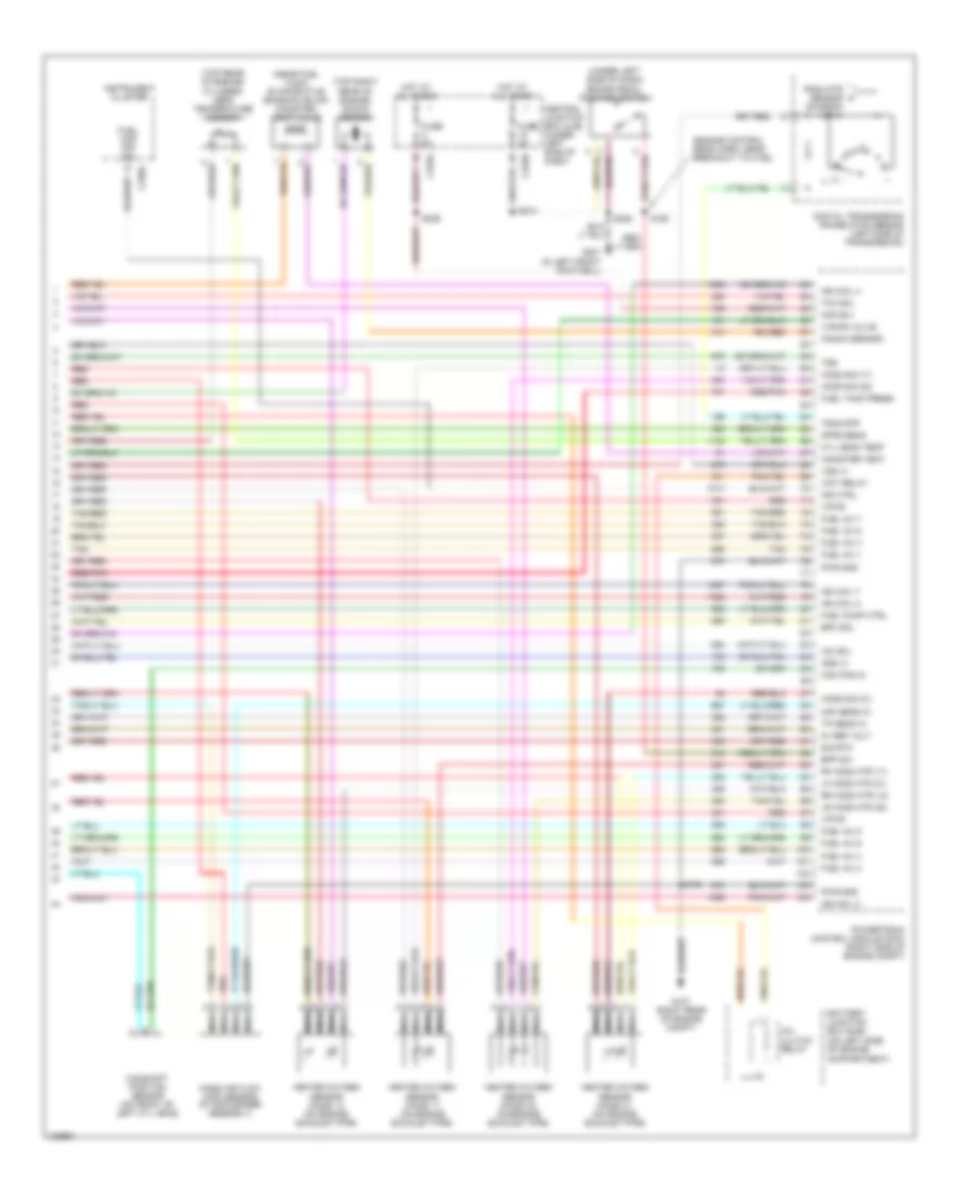
5.4L
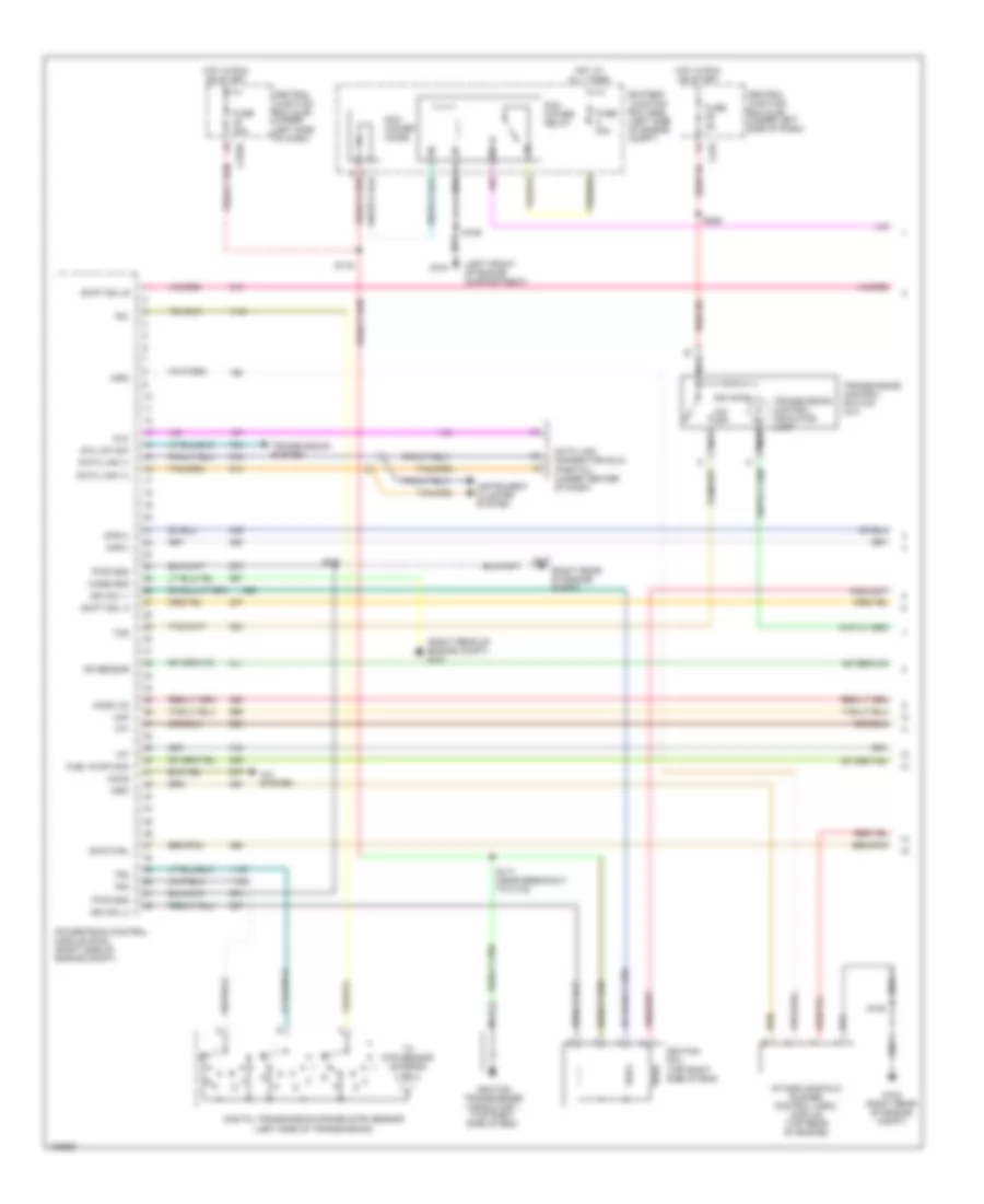
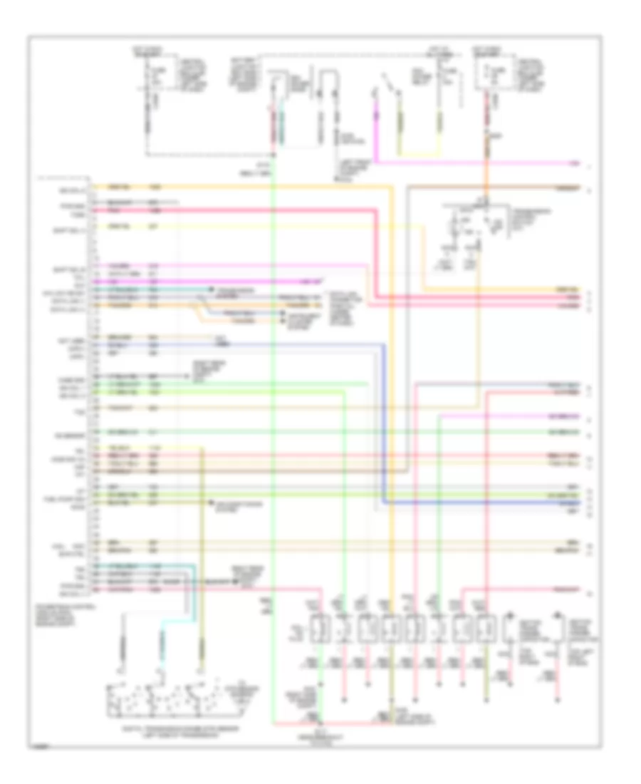
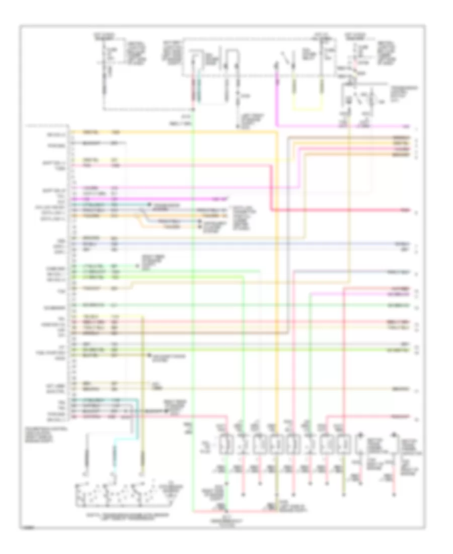
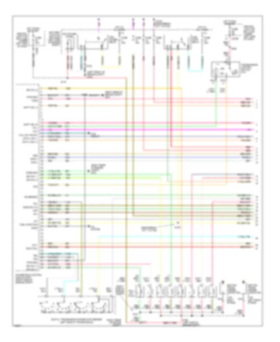
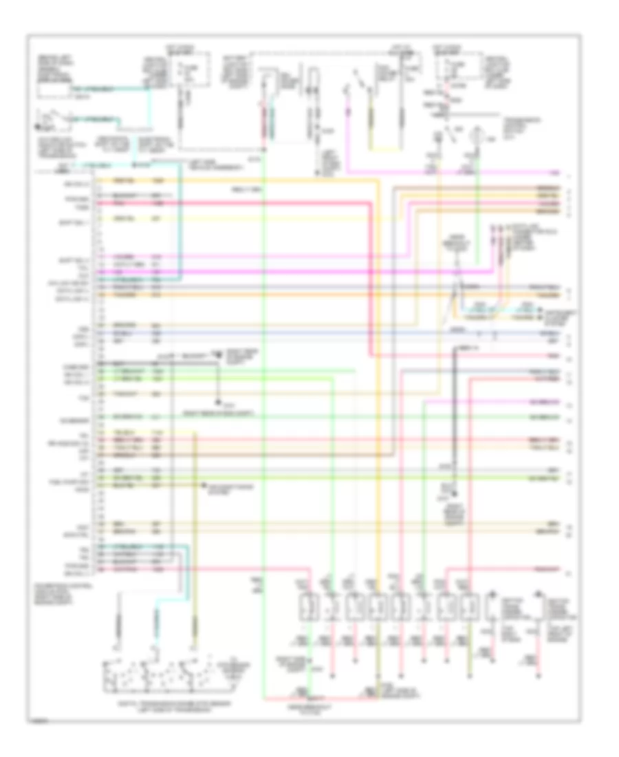
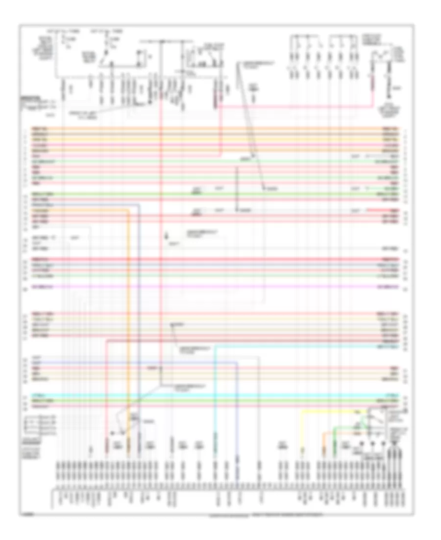
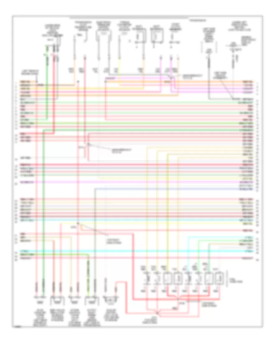
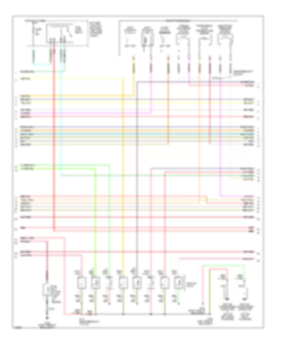
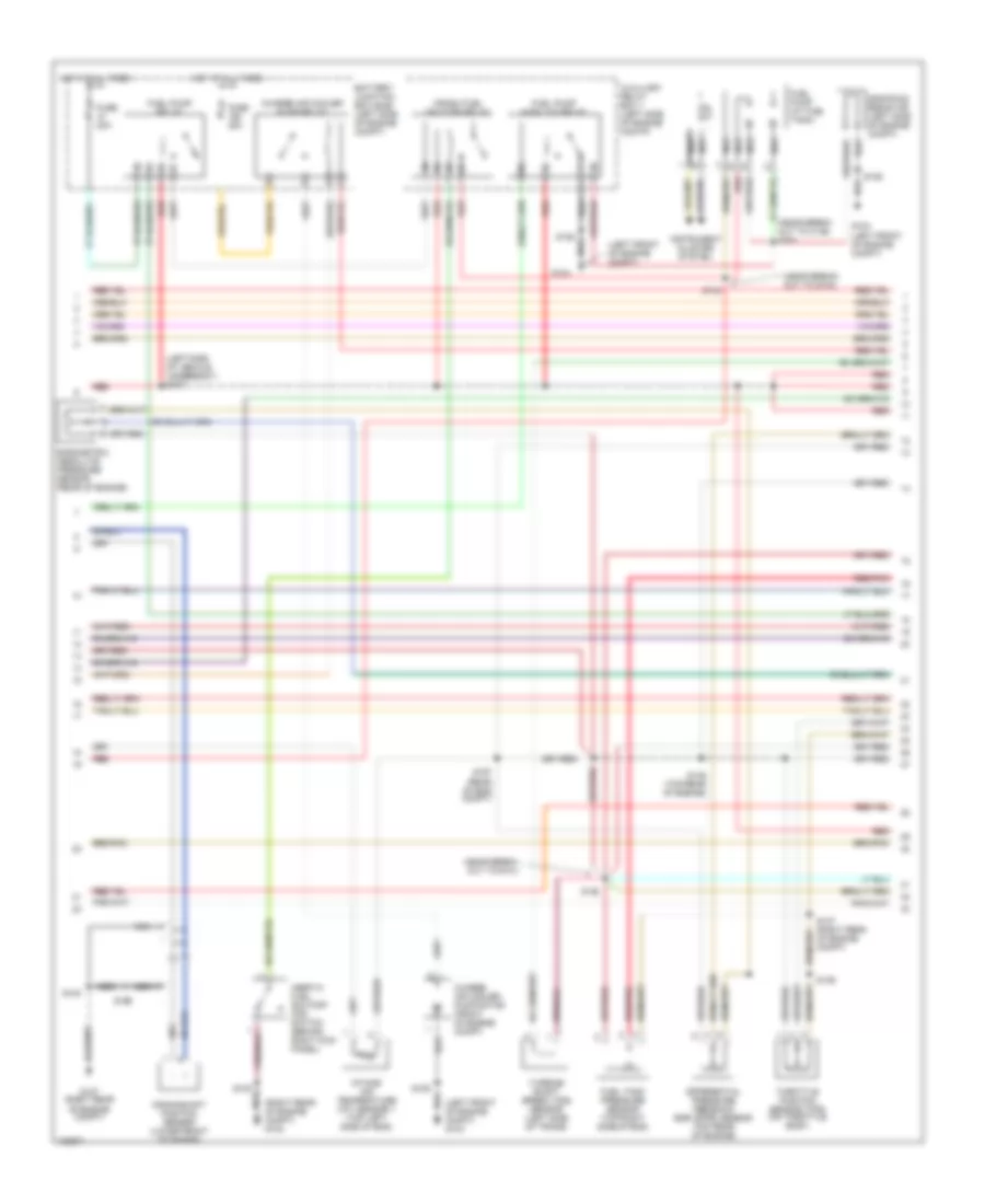
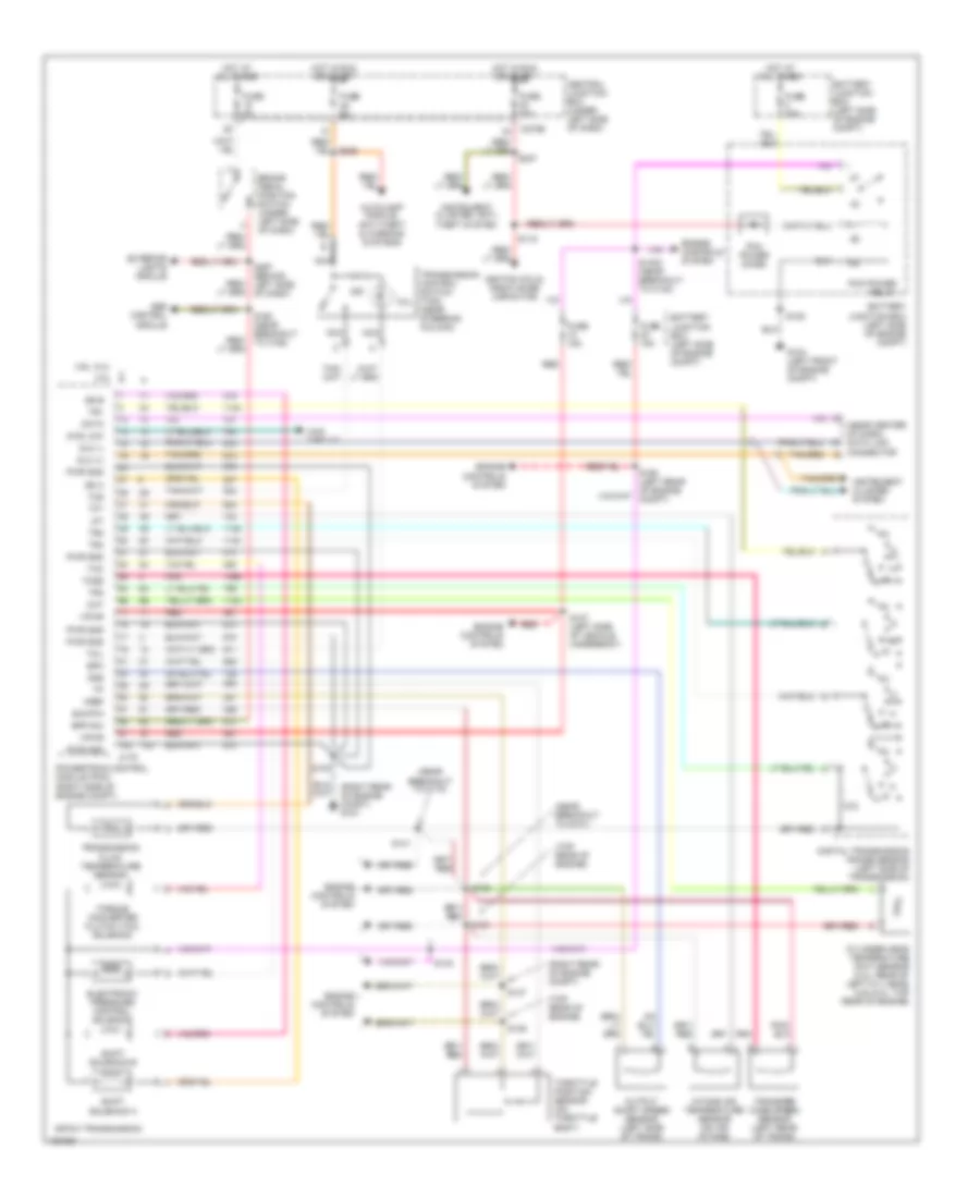
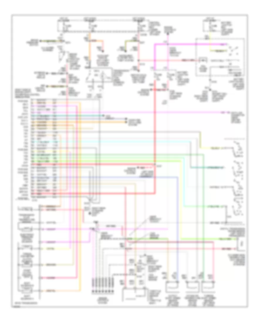
5.4L, Engine Performance Wiring Diagram, with 4R100 Transmission (1 of 4) for Ford Pickup Heritage F150 2004
List of elements for 5.4L, Engine Performance Wiring Diagram, with 4R100 Transmission (1 of 4) for Ford Pickup Heritage F150 2004:
- (left front of engine compt) g104
- (right rear of engine compt) g101
- (right rear of engine compt) g107
- 4x4 low ind sw
- Accs
- Air conditioning system
- B nca
- Battery junction box (bjb) (left side of engine compt)
- C270b
- Capacitor (top left front of engine)
- Case gnd
- Central junction box (cjb) (under left side of dash)
- Ckp(+)
- Ckp(-)
- Coil on plug
- Css
- Data link (+)
- Data link (-)
- Data link connector (partial) (under center of dash)
- Digital transmission range (dtr) sensor (left side of transmission)
- Dlc
- Evr ctrl
- Fuel pump mon
- Fuse 30a
- Fuse 5a
- Ho2s sig (12)
- Hot at all times
- Hot in run or start
- Iat
- Ign coil 1
- Ign coil 3
- Ign coil 5
- Ign coil 6
- Ignition trans- former
- Ignition trans- former capacitor (top right of engine)
- Ind
- Instrument cluster system
- Ks sensor
- Maf
- Nca
- Not used
- O/d off
- Pcm power diode
- Pcm power relay
- Pnk
- Powertrain control module (pcm) (right side of engine compt)
- Pwr gnd
- R n
- S100
- S105
- S116
- S117 (near breakout to c133)
- S161 (right side of engine compt)
- S162 (left side of engine compt)
- S225
- Shift sol a
- Shift sol b
- Tcil
- Tcs
- Tcss
- Tft
- To dtr sensor (diagram 4 of 4)
- Tr1
- Tr2
- Tr4
- Transmission control switch (a/t)
- Transmission system
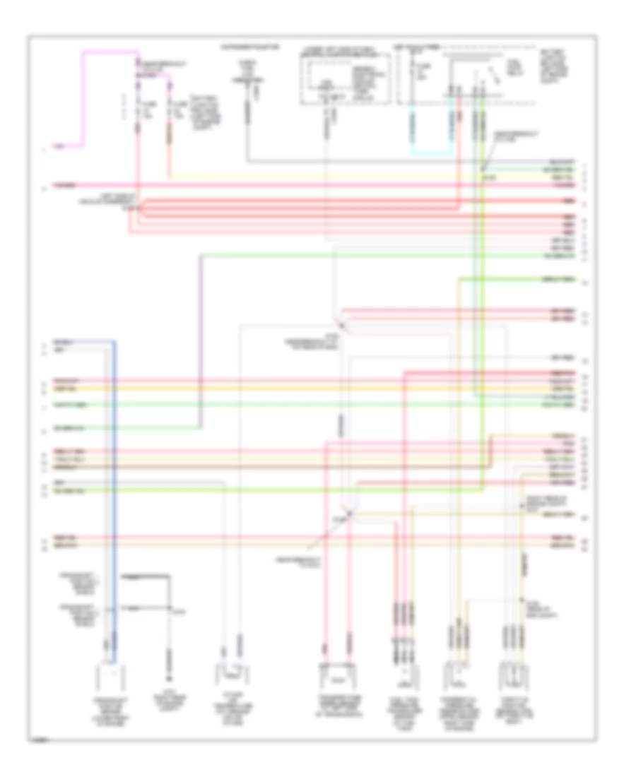
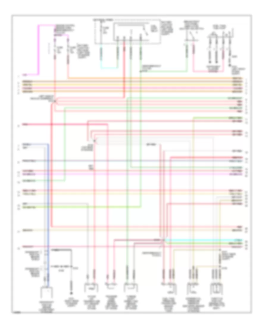
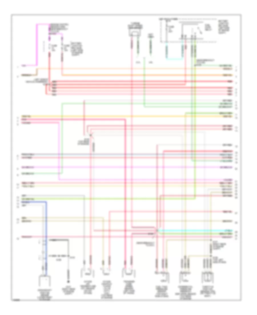
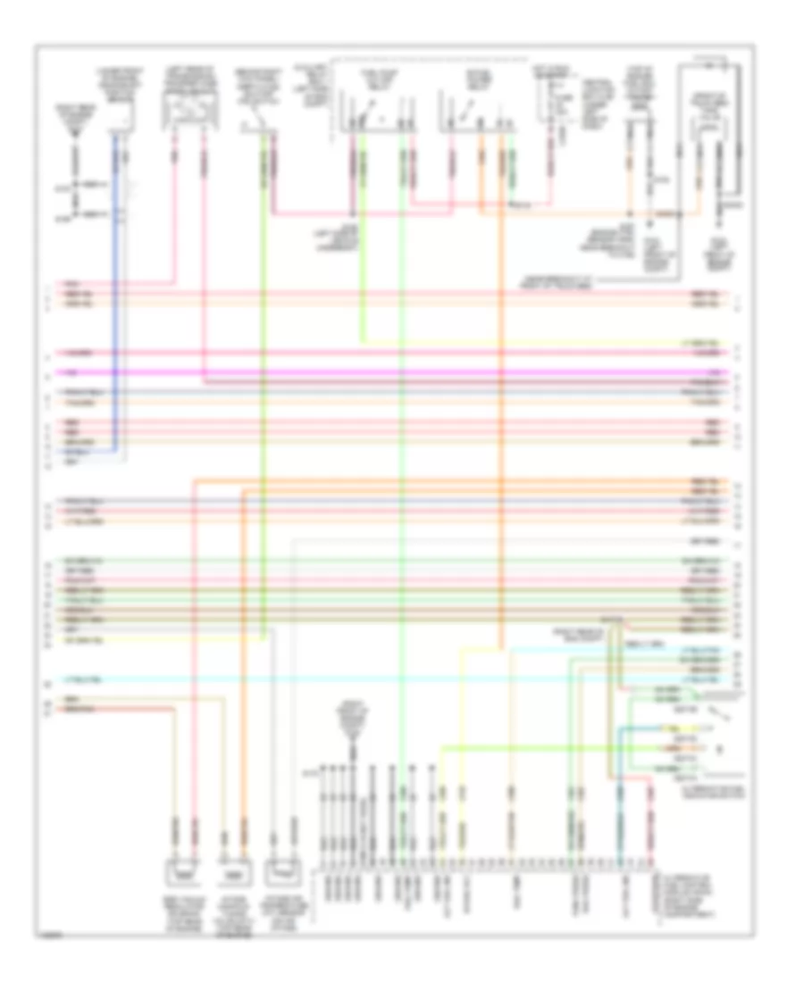
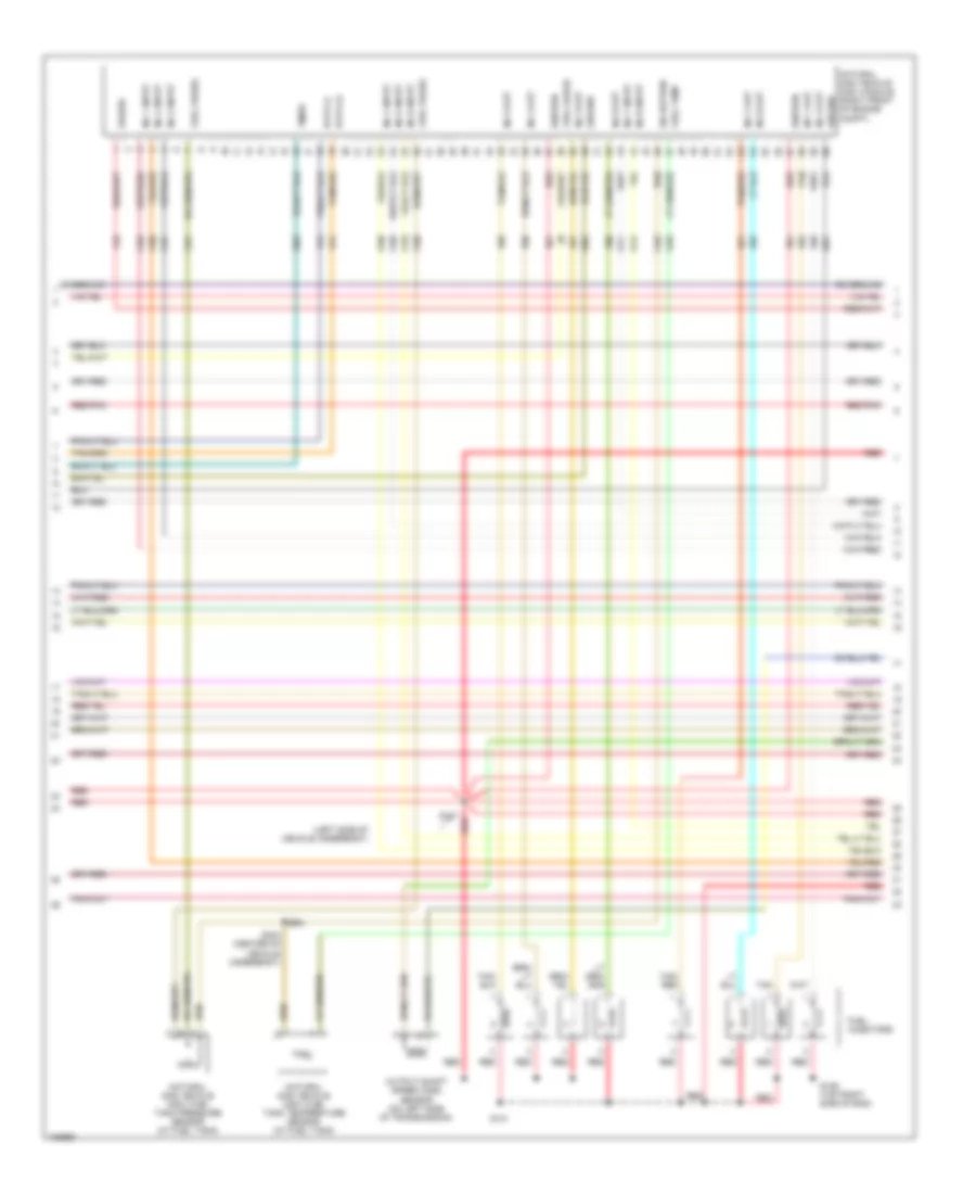
5.4L, Engine Performance Wiring Diagram, with 4R100 Transmission (2 of 4) for Ford Pickup Heritage F150 2004
List of elements for 5.4L, Engine Performance Wiring Diagram, with 4R100 Transmission (2 of 4) for Ford Pickup Heritage F150 2004:
- (behind right kick panel) inertia fuel shutoff (ifs) switch
- (fuel tank) fuel pump
- (left side of vehicle underbody) s127
- (near breakout to c192) s139
- (near breakout to g101)
- Battery junction box (bjb) (left side of engine compt)
- Crankshaft position sensor (lower front of engine)
- Crankshaft position sensor shield
- Differential pressure feedback egr (dpfe) sensor (top rear of engine)
- Fuel pump relay
- Fuel tank pressure transducer sensor (in fuel tank)
- Fuse 15a
- Fuse 20a
- G104 (left front of eng compt)
- G107 (right rear of engine compt)
- Hot at all times
- Instrument cluster system
- Intake air temperature (iat) sensor (on air intake)
- Nca
- Pnk
- Red
- Red/pnk
- S100
- S135 (top rear of engine)
- S136
- S137 (right rear of engine compt)
- S138
- S199
- S400
- Throttle position sensor (tps) (on throttle body)
- Transfer case speed sensor (left rear of trans)
- Turbine shaft speed (tss) sensor (left side of trans)
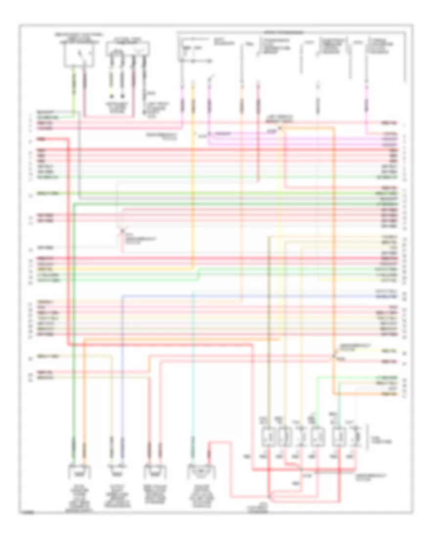
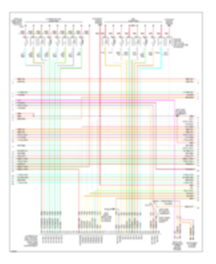
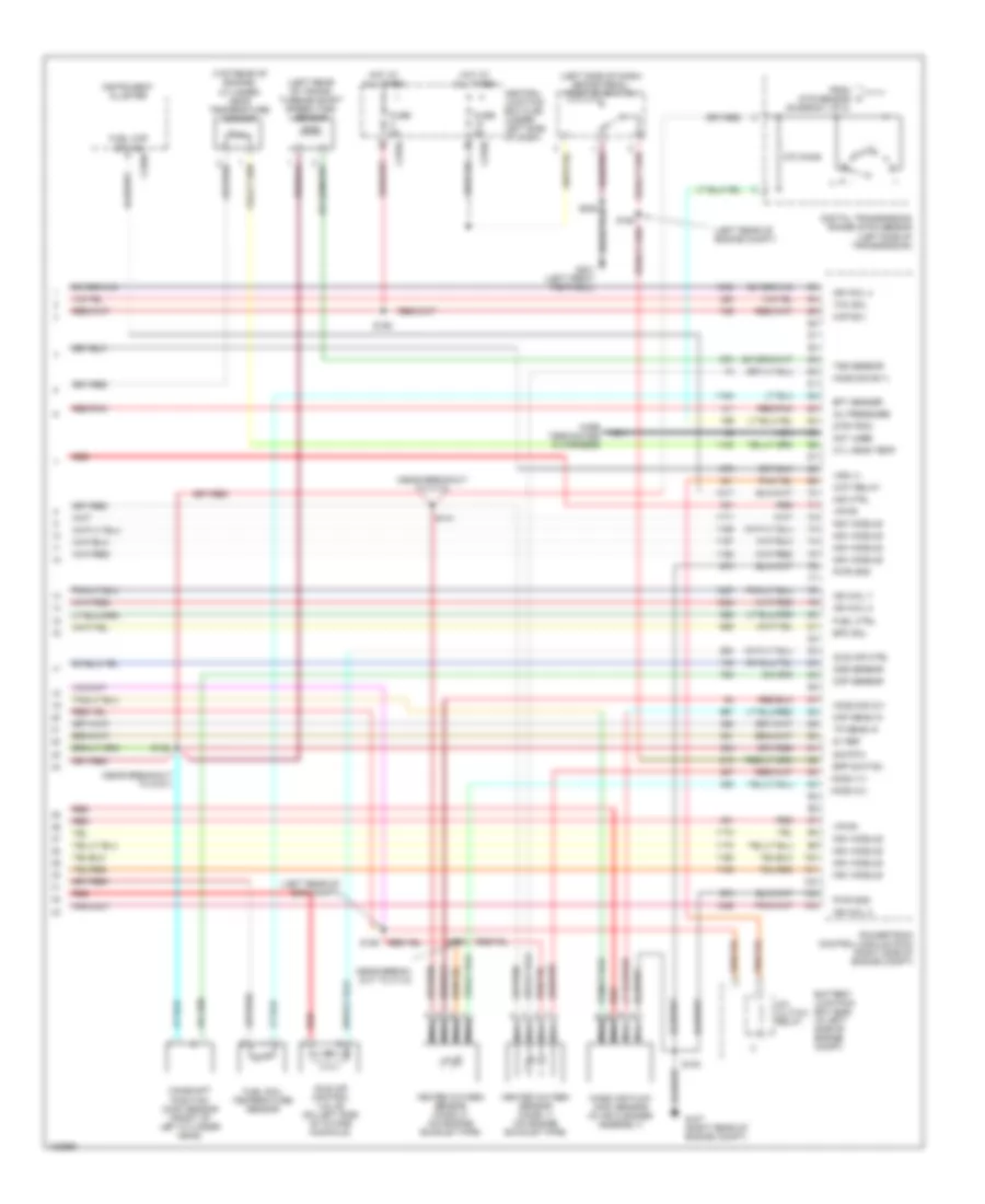
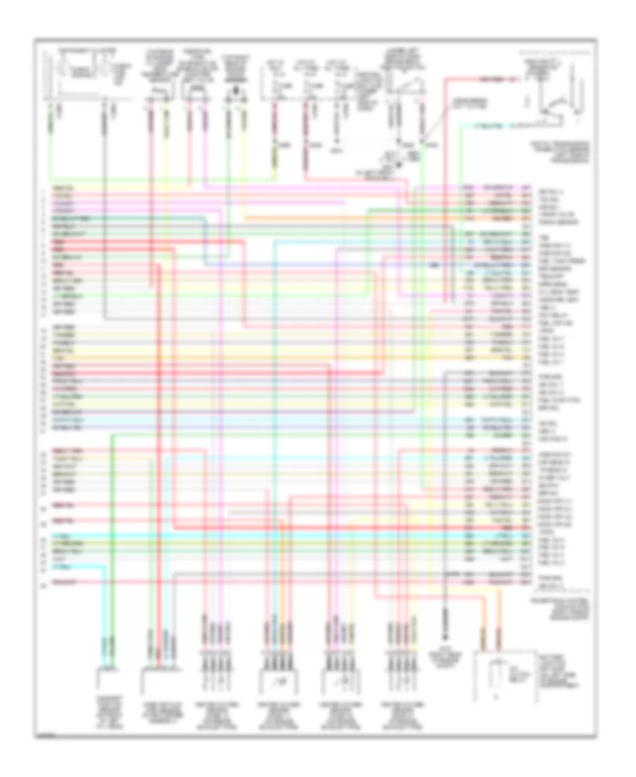
5.4L, Engine Performance Wiring Diagram, with 4R100 Transmission (3 of 4) for Ford Pickup Heritage F150 2004
List of elements for 5.4L, Engine Performance Wiring Diagram, with 4R100 Transmission (3 of 4) for Ford Pickup Heritage F150 2004:
- (left rear of engine compt)
- (left side of engine compt) speed control servo
- (left side of vehicle underbody)
- (near break- out to c140)
- (near breakout to c140)
- (top right side of eng)
- (top right side of engine)
- (under left side of dash) central junction box (cjb)
- 4r100 transmission
- C201d
- Coast clutch solenoid
- Egr vacuum regulator solenoid (top rear of engine)
- Electronic pressure control solenoid
- Evap canister purge
- Fuel injectors
- Generic electronic module (gem)
- Idle air control (iac) valve (top center of engine)
- Output shaft speed (oss) sensor (left side of transmission)
- Red
- Red/pnk
- S129
- S131 (top right side of eng)
- S140
- S141
- S143
- S154
- S155
- Shift solenoid a
- Shift solenoid b
- Tan
- Tan/ red
- Tan/red
- Torque converter clutch solenoid
- Transmission fluid temperature sensor
- Valve (left rear corner of engine compt)
- Vss input
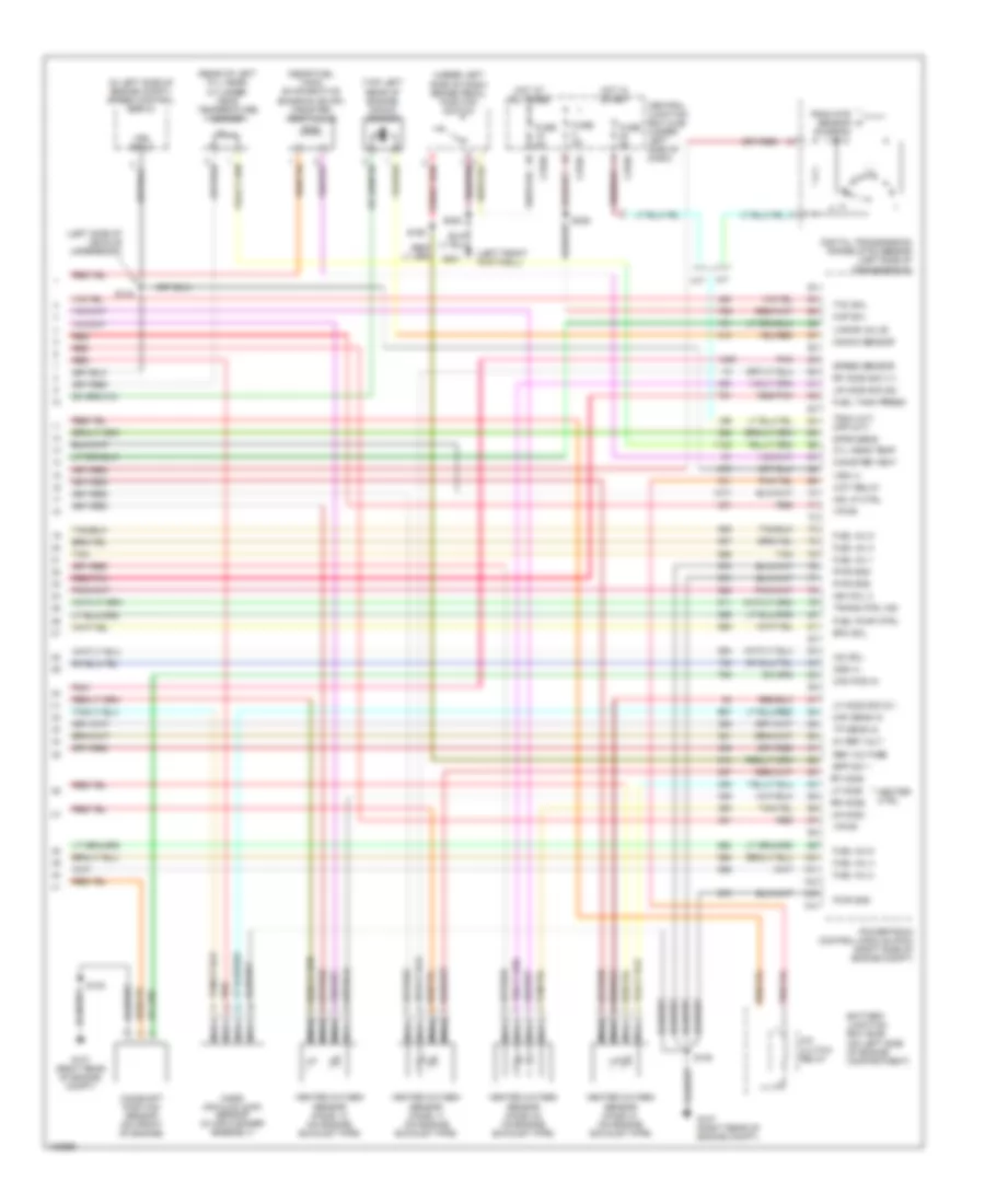
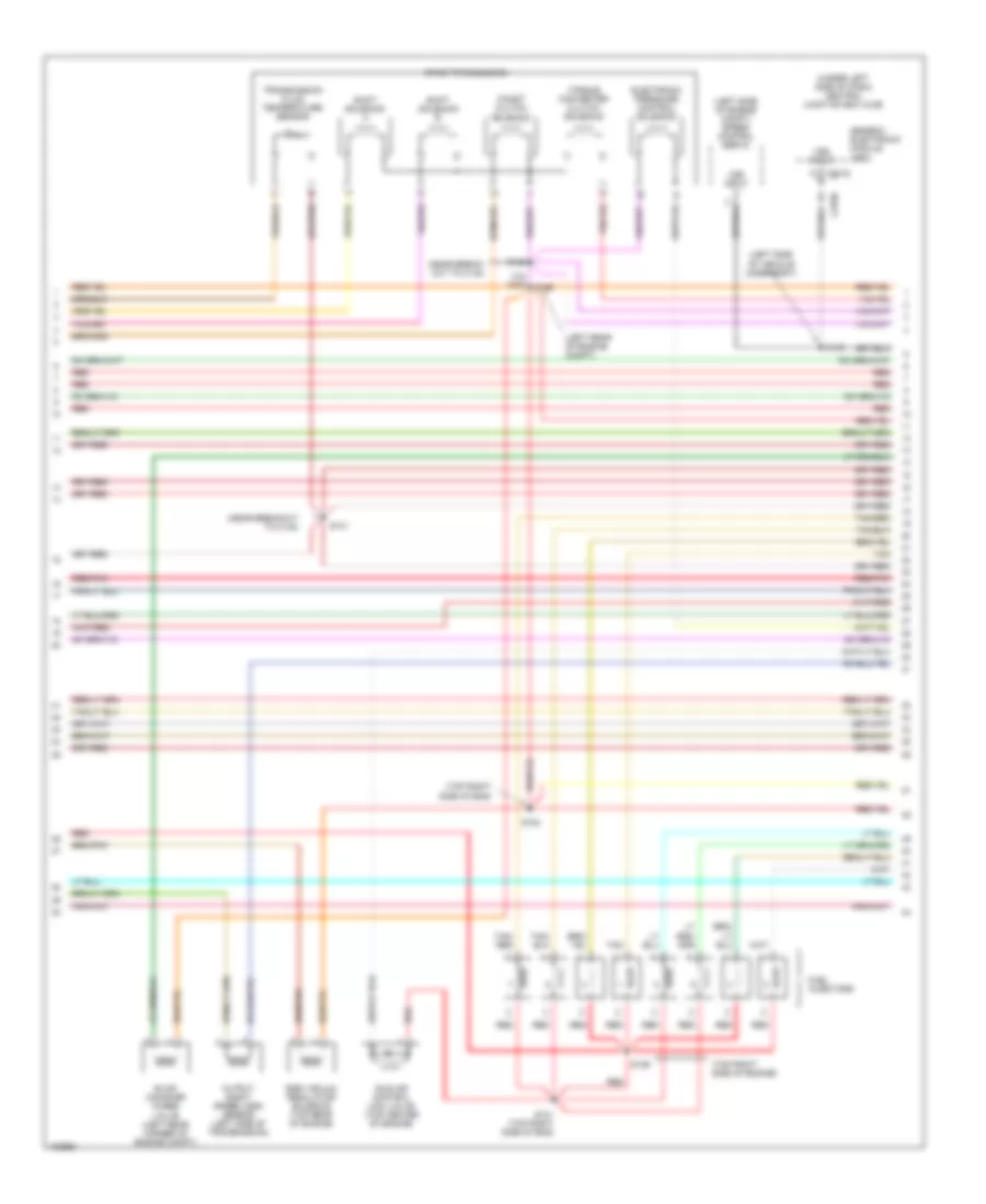
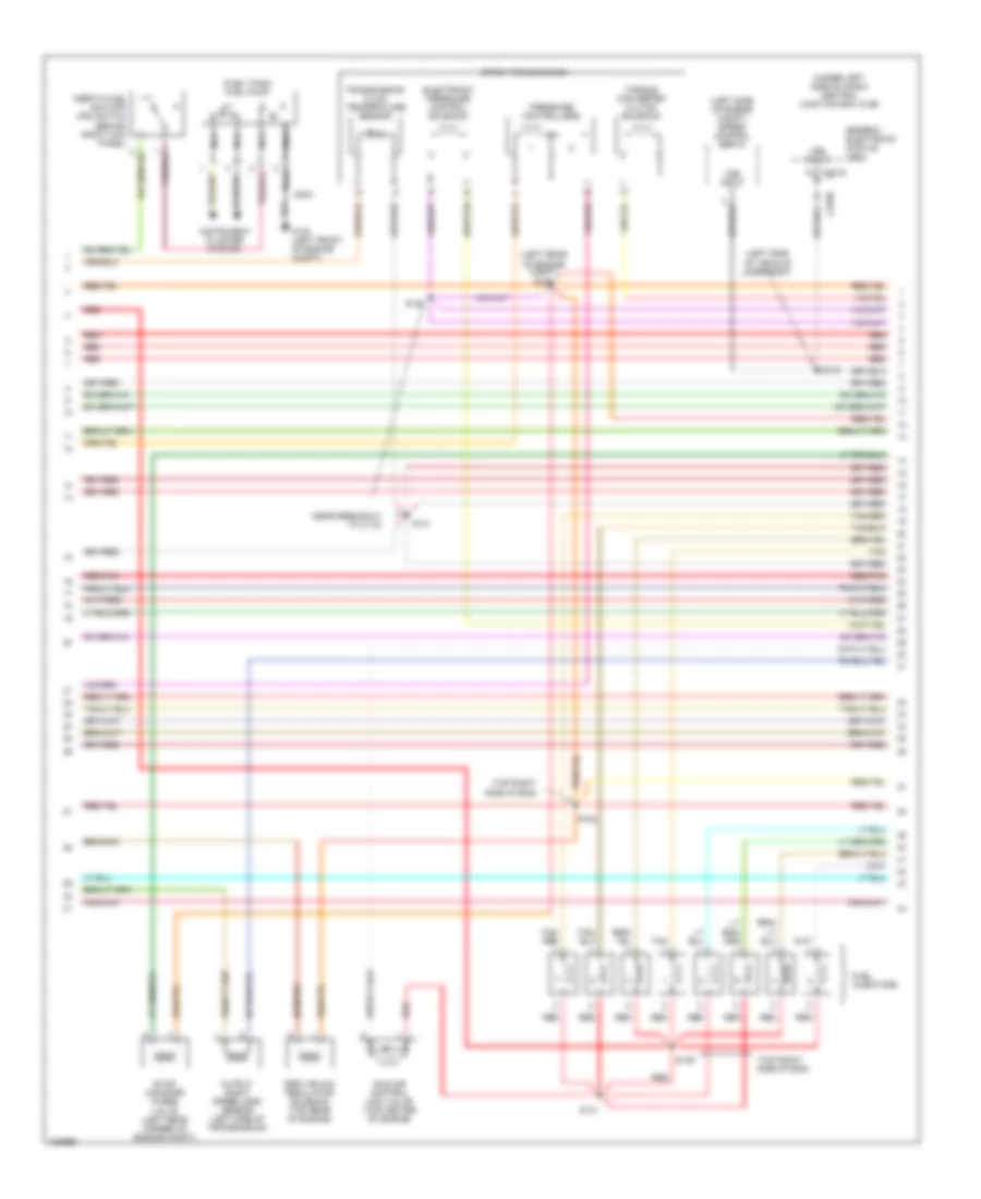
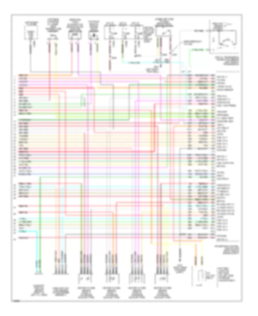
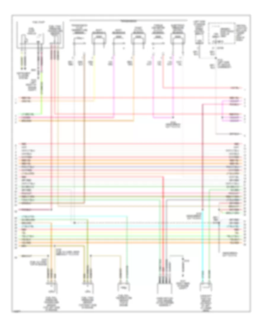
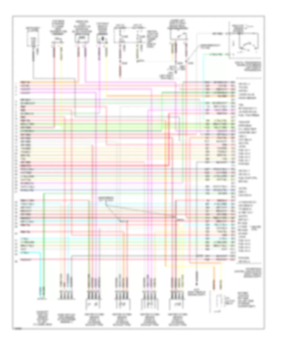
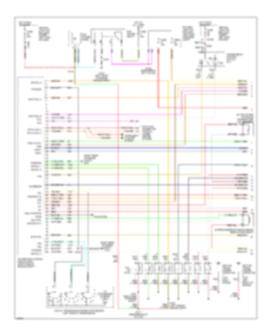
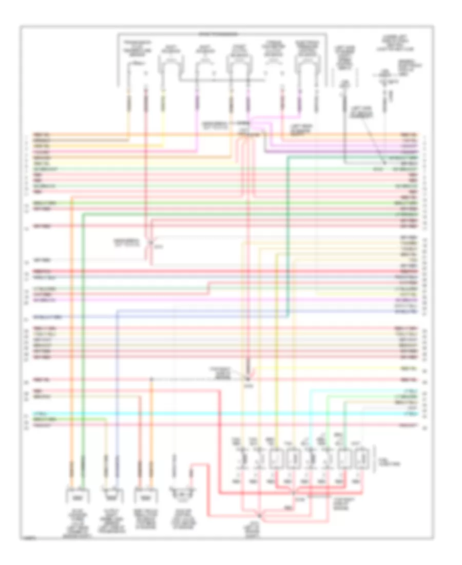
5.4L, Engine Performance Wiring Diagram, with 4R100 Transmission (4 of 4) for Ford Pickup Heritage F150 2004
List of elements for 5.4L, Engine Performance Wiring Diagram, with 4R100 Transmission (4 of 4) for Ford Pickup Heritage F150 2004:
- (engine control sens harn, near breakout to c192)
- (near fuel tank) evaporative emission (evap) canister vent valve
- (on left side of engine compartment)
- (top rear of engine) cylinder- head temperature sensor
- (top right rear of engine) knock sensor
- (under left side of dash) brake pedal position switch
- 5v ref volt
- A/c clutch relay
- Battery junction box (bjb)
- Bpp sw
- Cam pos in
- Camshaft position sensor (on front of left cyl head)
- Canister vent
- Central junction box (cjb) (under left side of dash)
- Cyl head temp
- Digital transmission range (dtr) sensor (left side of transmission)
- Dpfe sens
- Epc sol
- From dtr sensor (diagram 1 of 4)
- Fuel cap off ind
- Fuel inj 1
- Fuel inj 2
- Fuel inj 3
- Fuel inj 4
- Fuel inj 5
- Fuel inj 6
- Fuel inj 7
- Fuel inj 8
- Fuel pump ctrl
- Fuel tank press
- Fuse 5a
- G107 (right rear of engine compt)
- G201 (in left front footwell)
- Heated oxygen sensor (ho2s) 11 (on engine exhaust pipe)
- Heated oxygen sensor (ho2s) 12 (on engine exhaust pipe)
- Heated oxygen sensor (ho2s) 21 (on engine exhaust pipe)
- Heated oxygen sensor (ho2s) 22 (on engine exhaust pipe)
- Ho2s sig (11)
- Ho2s sig (21)
- Ho2s sig (22)
- Hot at all times
- Iac sol
- Ign coil 2
- Ign coil 4
- Ign coil 7
- Ign coil 8
- Ind ctrl
- Instrument cluster
- Kap b(+)
- Knock sensor
- Lf ho2s htr (21)
- Lr ho2s htr (22)
- Maf sens in
- Mass air flow (maf) sensor (in air cleaner assembly)
- Nca
- Oss (+)
- Powertrain control module (pcm) (right side of engine compt)
- Pwr gnd
- Red
- Red/pnk
- Rf ho2s htr (11)
- Rr ho2s htr (12)
- S100
- S160
- S208
- S236
- S274
- Sig rtn
- Tan
- Tan/red
- Tcc sol
- Tp sens in
- Tr3a/cpp
- Tss
- Vapor valve
- Vpwr
- Vss (+)
- Wot relay
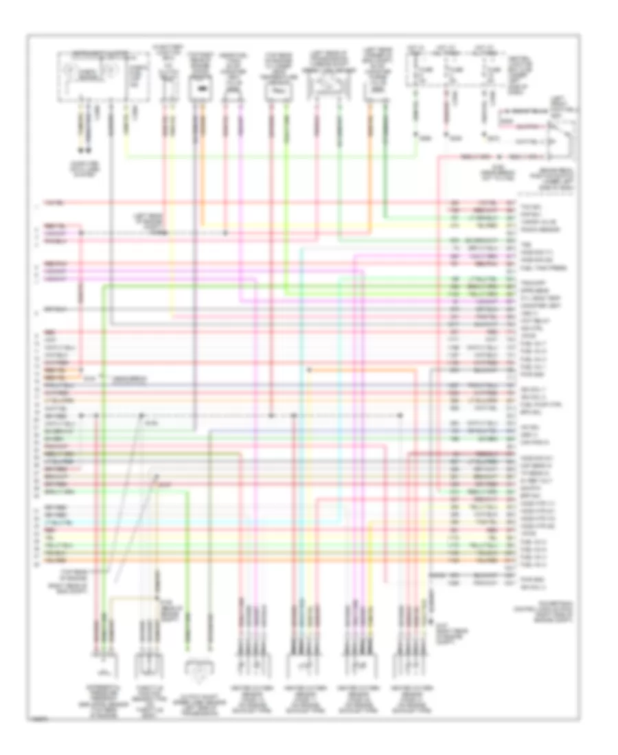
5.4L, Engine Performance Wiring Diagram, with 4R70W Transmission (1 of 4) for Ford Pickup Heritage F150 2004
List of elements for 5.4L, Engine Performance Wiring Diagram, with 4R70W Transmission (1 of 4) for Ford Pickup Heritage F150 2004:
- (4.6l)
- (left front of engine compt) g104
- (right rear of engine compt) g101
- (right rear of engine compt) g107
- 4x4 low ind sw
- Accs
- Air conditioning system
- Battery junction box (bjb) (left side of engine compt)
- Capacitor (top left front of eng)
- Case gnd
- Central junction box (cjb) (under left side of dash)
- Ckp(+)
- Ckp(-)
- Coil on plug
- Data link (+)
- Data link (-)
- Data link connector (partial) (under center of dash)
- Digital transmission range (dtr) sensor (left side of transmission)
- Dlc
- Evr ctrl
- Fuel pump mon
- Fuse 30a
- Fuse 5a
- Ho2s sig (12)
- Hot at all times
- Hot in run or start
- Iat
- Ign coil 1
- Ign coil 3
- Ign coil 5
- Ign coil 6
- Ignition trans- former
- Ignition trans- former capacitor (top right of eng)
- Imcc
- Ind
- Instrument cluster system
- Ks sensor
- Maf
- Nca
- Not used
- O/d off
- Pcm power diode
- Pcm power relay
- Pnk
- Powertrain control module (pcm) (right side of engine compt)
- Pwr gnd
- R n
- S100
- S106 (or s105)
- S116
- S117 (near breakout to c133)
- S161 (right side of engine compt)
- S162 (left side of engine compt)
- Shift sol a
- Shift sol b
- Tcil
- Tcs
- Tcss
- Tft
- To dtr sensor (diagram 4 of 4)
- Tr1
- Tr2
- Tr4
- Transmission control switch (a/t)
- Transmission system
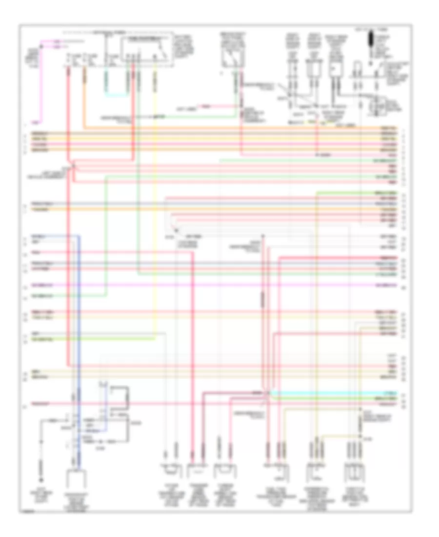
5.4L, Engine Performance Wiring Diagram, with 4R70W Transmission (2 of 4) for Ford Pickup Heritage F150 2004
List of elements for 5.4L, Engine Performance Wiring Diagram, with 4R70W Transmission (2 of 4) for Ford Pickup Heritage F150 2004:
- (left side of vehicle underbody) s127
- (near breakout to c192) s139
- (near breakout to g101)
- (not used)
- 4.6l
- 5.4l
- Battery junction box (bjb) (left side of engine compt)
- Crankshaft position sensor (lower front of engine)
- Differential pressure feedback egr (dpfe) sensor (top rear of engine)
- Fuel pump relay
- Fuel tank pressure sensor (top right side of eng)
- Fuse 15a
- Fuse 20a
- G107 (right rear of engine compt)
- Hot at all times
- Intake air temperature (iat) sensor (on air intake)
- Intake manifold tuning valve (imtv) (4.6l) (top rear of engine)
- Nca
- Pnk
- Red
- Red/pnk
- S100
- S135 (top rear of engine)
- S136 (top left side of eng)
- S137 (right rear of engine compt)
- S138
- S199
- Throttle position sensor (tps) (on throttle body)
- Transfer case speed sensor (left side of trans)
- Turbine shaft speed (tss) sensor
5.4L, Engine Performance Wiring Diagram, with 4R70W Transmission (3 of 4) for Ford Pickup Heritage F150 2004
List of elements for 5.4L, Engine Performance Wiring Diagram, with 4R70W Transmission (3 of 4) for Ford Pickup Heritage F150 2004:
- (fuel tank) fuel pump
- (left rear of engine compt) s155
- (left side of engine compt) speed control servo
- (left side of vehicle underbody
- (near breakout to c110)
- (top right side of eng)
- (under left side of dash) central junction box (cjb)
- 4r70w transmission
- C201d
- Egr vacuum regulator solenoid (top rear of engine)
- Electronic pressure control solenoid
- Evap canister purge
- Fuel injectors
- G104 (left front of engine compt)
- Generic electronic module (gem)
- Idle air control (iac) valve (top center of engine)
- Inertia fuel shutoff (ifs) switch (behind right kick panel)
- Instrument cluster system
- Nca
- Output shaft speed (oss) sensor (left side of transmission)
- Pressure controllers
- Red
- Red/pnk
- S129
- S131
- S140
- S141
- S143
- S154
- S400
- Tan
- Tan/ red
- Tan/red
- Torque converter clutch solenoid
- Transmission fluid temperature sensor
- Valve (left rear corner of engine compt)
- Vss input
5.4L, Engine Performance Wiring Diagram, with 4R70W Transmission (4 of 4) for Ford Pickup Heritage F150 2004
List of elements for 5.4L, Engine Performance Wiring Diagram, with 4R70W Transmission (4 of 4) for Ford Pickup Heritage F150 2004:
- (5.4l)
- (near breakout to c192)
- (near fuel tank) evaporative emission evap) canister vent valve
- (on left side of engine compartment)
- (top rear of engine) cylinder- head temperature sensor
- (top right rear of engine) knock sensor
- (under left side of dash) brake pedal position switch
- 5v ref volt
- A/c clutch relay
- A/t
- Battery junction box (bjb)
- Bpp sw
- Cam pos in
- Camshaft position sensor (front of left cyl head)
- Canister vent
- Central junction box (cjb) (under left side of dash)
- Check fuel cap ind
- Cyl head temp
- Digital transmission range (dtr) sensor (left side of transmission)
- Dpfe sens
- Epc sol
- From dtr sensor (diagram 1 of 4)
- Fuel inj 1
- Fuel inj 2
- Fuel inj 3
- Fuel inj 4
- Fuel inj 5
- Fuel inj 6
- Fuel inj 7
- Fuel inj 8
- Fuel pump ctrl
- Fuel tank press
- Fuse 5a
- G107 (right rear of engine compt)
- G201 (left front footwell)
- Heated oxygen sensor (ho2s) 11 (on engine exhaust pipe)
- Heated oxygen sensor (ho2s) 12 (on engine exhaust pipe)
- Heated oxygen sensor (ho2s) 21 (on engine exhaust pipe)
- Heated oxygen sensor (ho2s) 22 (on engine exhaust pipe)
- Ho2s sig (11)
- Ho2s sig (21)
- Ho2s sig (22)
- Hot at all times
- Hot in start
- Iac sol
- Ign coil 2
- Ign coil 4
- Ign coil 7
- Ign coil 8
- Ind ctrl
- Instrument cluster
- Kap b(+)
- Knock sensor
- Lf ho2s htr (21)
- Lr ho2s htr (22)
- M/t
- Maf sens in
- Mass air flow (maf) sensor (in air cleaner assembly)
- Nca
- Oss (+)
- Powertrain control module (pcm) (right side of engine compt)
- Pwr gnd
- Red
- Red/pnk
- Rf ho2s htr (11)
- Rr ho2s htr (12)
- S100
- S160
- S208
- S236
- S274
- Sig rtn
- Tan
- Tan/red
- Tcc sol
- Tp sens in
- Tr3a/cpp
- Tss
- Vapor valve
- Vpwr
- Vss (+)
- Wot relay
5.4L BI-FUEL GAS/CNG
5.4L Bi-Fuel Gas/CNG, Engine Performance Wiring Diagram (1 of 5) for Ford Pickup Heritage F150 2004
List of elements for 5.4L Bi-Fuel Gas/CNG, Engine Performance Wiring Diagram (1 of 5) for Ford Pickup Heritage F150 2004:
- (left front of engine compt) g104
- (near break- out to c192)
- (right rear of engine compt)
- (right rear of engine compt) g101
- (right rear of engine compt) g107
- (right side of engine compt)
- 4wd circuit
- 4x4 low ind sw
- A/c system
- Accs
- Battery junction box (bjb) (left side of engine compt)
- C270b
- Case gnd
- Central junction box (cjb) (under left side of dash)
- Ckp(+)
- Ckp(-)
- Coil on plug
- Css
- Data link (+)
- Data link (-)
- Digital transmission range (dtr) sensor (left side of transmission)
- Dlc
- Evr ctrl
- Fuel pump mon
- Fuel pump relay
- Fuse 15a
- Fuse 20a
- Fuse 30a
- Fuse 5a
- Ho2s sig (12)
- Hot at all times
- Hot in run or start
- Iat
- Ign coil 1
- Ign coil 3
- Ign coil 4
- Ign coil 5
- Ign coil 6
- Ignition trans- former capacitor (top left front of eng)
- Ignition trans- former capacitor (top right of eng)
- Imtv
- Ind
- Ks sensor
- Maf
- Nca
- O/d off
- Pcm power diode
- Pcm power relay
- Pnk
- Powertrain control module (pcm) (right side of engine compt)
- Pwr gnd
- R n
- Red
- S100
- S105
- S116
- S117
- S139
- S161
- S162 (left side of engine compt)
- S225
- Shift sol a
- Shift sol b
- Tcil
- Tcs
- Tcss
- Tft
- Tr1
- Tr2
- Tr4
- Transmission control switch (a/t)
5.4L Bi-Fuel Gas/CNG, Engine Performance Wiring Diagram (2 of 5) for Ford Pickup Heritage F150 2004
List of elements for 5.4L Bi-Fuel Gas/CNG, Engine Performance Wiring Diagram (2 of 5) for Ford Pickup Heritage F150 2004:
- (behind right kick panel) inertia fuel shutoff (ifs) switch
- (front of truck bed) tank valve
- (left rear of transmission) transfer case speed sensor
- (lower front of engine) crankshaft position sensor
- (near breakout at front of truck bed)
- (pins 5-16 not used)
- (right front of engine compt) g108
- (right rear of eng compt)
- (right rear of engine compt) g107
- (right side of engine compartment)
- (top of engine) fuel rail cutoff valve
- (top rear of engine)
- 87a
- Alt fuel ind
- Alternative fuel control module (afcm)
- Alternative fuel indicator switch
- Auxiliary relay box 1 (left side of eng compt)
- Bi-fuel power relay
- Bi-fuel rly
- C2270a
- C2270b
- C2270c
- C2270d
- C270b
- Central junction box (cjb) (under left side of dash)
- Egr vacuum regulator solenoid
- Fuel pump
- Fuel pump cut-off relay
- Fuse 30a
- G104 (left front of engine compt)
- Ground
- Hot in run or start
- Intake air temperature (iat) sensor (on air intake)
- Intake manifold tuning valve (imtv) (top rear of engine)
- Nca
- Pnk
- Rail press
- Rail temp
- Red
- S100
- S116
- S175
- S177
- S189 (left side of vehicle underbody)
- S191 (engine ctrl sensor harn, near breakout to c192)
- S199
- S4023
- Start/run
- Tank press
5.4L Bi-Fuel Gas/CNG, Engine Performance Wiring Diagram (3 of 5) for Ford Pickup Heritage F150 2004
List of elements for 5.4L Bi-Fuel Gas/CNG, Engine Performance Wiring Diagram (3 of 5) for Ford Pickup Heritage F150 2004:
- (fuel inj harn, near breakout to c1019)
- (left side of vehicle underbody)
- (left side of vehicle underbody) s127
- (right rear of engine compt)
- (right side of engine compartment)
- (top right side of engine) s129
- (top right side of engine) s131
- Alt inj 1
- Alt inj 2
- Alt inj 3
- Alt inj 4
- Alt inj 5
- Alt inj 6
- Alt inj 7
- Alt inj 8
- Alternate fuel injectors
- Alternative fuel control module (afcm)
- Data link connector (under center of dash)
- Fuel injectors
- G103 (right front side of vehicle exterior)
- Ground
- Idle air control (iac) valve (on top center of engine)
- Inj 1
- Inj 2
- Inj 3
- Inj 4
- Inj 5
- Inj 6
- Inj 7
- Inj 8
- Instrument cluster system
- Pcm inj 1
- Pcm inj 2
- Pcm inj 3
- Pcm inj 4
- Pcm inj 5
- Pcm inj 6
- Pcm inj 7
- Pcm inj 8
- Red
- Ref volt
- S104
- S179
- S181
- S187
- Scp bus +
- Scp bus -
- Sig ret
- Start/run
- Tan
- Tan/ red
- Tan/red
5.4L Bi-Fuel Gas/CNG, Engine Performance Wiring Diagram (4 of 5) for Ford Pickup Heritage F150 2004
List of elements for 5.4L Bi-Fuel Gas/CNG, Engine Performance Wiring Diagram (4 of 5) for Ford Pickup Heritage F150 2004:
- (left side of engine compt) speed control servo
- (near break- out to c110)
- C201d
- C270b
- Camshaft position sensor (on front of left cylinder head)
- Central junction box (cjb) (under left side of dash)
- Coast clutch solenoid
- Electronic pressure control solenoid
- Fuel pump
- Fuel pump module
- Fuel rail pressure transducer sensor (top left side of engine)
- Fuel rail temperature sensor (top of engine)
- Fuel tank pressure sensor (top right side of engine)
- Fuel tank pressure transducer sensor
- G104 (left front of engine compt)
- G107 (right rear of engine compt)
- Generic electronic module (gem)
- Instrument cluster system
- Mass air flow (maf) sensor (in air cleaner assembly)
- Nca
- Red
- Red/pnk
- S100
- S138 (near break- out to g101)
- S140 (near break- out to c110)
- S141
- S143 (left side of vehicle underbody)
- S183 (fuel inj harn, top of engine)
- S185 (fuel inj harn, near breakout to c1019)
- S400
- Shift solenoid a
- Shift solenoid b
- Torque converter clutch solenoid
- Transmission
- Transmission fluid temperature sensor
- Vss input
5.4L Bi-Fuel Gas/CNG, Engine Performance Wiring Diagram (5 of 5) for Ford Pickup Heritage F150 2004
List of elements for 5.4L Bi-Fuel Gas/CNG, Engine Performance Wiring Diagram (5 of 5) for Ford Pickup Heritage F150 2004:
- (in battery junction box)
- (left front footwell) g201
- (left rear corner of eng compt) evap canister purge valve
- (left rear of engine compt) s155
- (left rear of transmission) turbine shaft speed (tss) sensor
- (near break- out to c110)
- (near fuel tank) evap canister vent valve
- (right rear of eng compt)
- (top rear of engine)
- (top rear of engine) cylinder- head temperature sensor
- (top right rear of engine) knock sensor
- 5v ref volt
- A/c clutch relay
- Bpp sw
- Brake pedal position switch (under left side of dash)
- C270a
- C270b
- Cam pos in
- Canister vent
- Central junction box (cjb) (under left side of dash)
- Check engine
- Check fuel cap ind
- Computer data lines system
- Cyl head temp
- Differential pressure feedback egr (dpfe) sensor (top rear of engine)
- Dpfe sens
- Epc sol
- Fuel inj 1
- Fuel inj 2
- Fuel inj 3
- Fuel inj 4
- Fuel inj 5
- Fuel inj 6
- Fuel inj 7
- Fuel inj 8
- Fuel pump ctrl
- Fuel tank press
- Fuse 5a
- G107 (right rear of engine compt)
- Heated oxygen sensor (ho2s) 11 (on engine exhaust pipe)
- Heated oxygen sensor (ho2s) 12 (on engine exhaust pipe)
- Heated oxygen sensor (ho2s) 21 (on engine exhaust pipe)
- Heated oxygen sensor (ho2s) 22 (on engine exhaust pipe)
- Ho2s htr (11)
- Ho2s htr (12)
- Ho2s htr (21)
- Ho2s htr (22)
- Ho2s sig (11)
- Ho2s sig (21)
- Ho2s sig (22)
- Hot at all times
- Hot in run
- Iac sol
- Ign coil 2
- Ign coil 7
- Ign coil 8
- Ind ctrl
- Instrument cluster
- Kap b(+)
- Knock sensor
- Maf sens in
- Nca
- Oss (+)
- Output shaft speed (oss) sensor (left side of transmission)
- Powertrain control module (pcm) (right side of engine compt)
- Pwr gnd
- Red
- Red/pnk
- S100
- S135
- S136 (rear of engine compt)
- S137
- S154
- S160 (near break- out to c192)
- S208
- S236
- S265
- S274
- Sig rtn
- Tcc sol
- Throttle position sensor (tps) (on throttle body)
- Tp sens in
- Tr3a/cpp
- Tss
- Vapor valve
- Vpwr
- Vss (+)
- Wot relay
5.4L BI-FUEL GAS/LPG
5.4L Bi-Fuel Gas/LPG, Engine Performance Wiring Diagram (1 of 5) for Ford Pickup Heritage F150 2004
List of elements for 5.4L Bi-Fuel Gas/LPG, Engine Performance Wiring Diagram (1 of 5) for Ford Pickup Heritage F150 2004:
- (behind left side of dash) generic electronic module (gem)
- (left front of eng compt) g104
- (left side vehicle underbody)
- (near breakout to c133)
- (near breakout to c432)
- (right rear of eng compt)
- (right rear of engine compt)
- (right side of engine compt)
- 4x4 high/low indicator switch (left side of transmission)
- 4x4 low ind sw
- 4x2
- Accs
- Air conditioning system
- Battery junction box (bjb) (left side of engine compt)
- C201a
- C270b
- Case gnd
- Center of dash)
- Central junction box (cjb) (under left side of dash)
- Ckp(+)
- Ckp(-)
- Css
- Data link (+)
- Data link (-)
- Digital transmission range (dtr) sensor (left side of transmission)
- Dlc
- Electronic shift on the fly (esof)
- Evr ctrl
- Fuel pump mon
- Fuse 30a
- Fuse 5a
- G101
- G107
- Hot at all times
- Hot in run or start
- Iat
- Ign coil 1
- Ign coil 3
- Ign coil 5
- Ign coil 6
- Ignition trans- former capacitor (top left front of engine)
- Ignition trans- former capacitor (top right of eng)
- Imcc
- Ind
- Instrument cluster system
- Ks sensor
- Maf
- Mechanical shift on the fly (msof)
- Nca
- Not used
- O/d off
- Pcm power diode
- Pcm power relay
- Pnk
- Powertrain control module (pcm) (right side of engine compt)
- Pwr gnd
- R n
- Rr ho2s sig (12)
- S100
- S105
- S116
- S142
- S161
- S162 (left side of engine compt)
- S225
- S4003
- S4004
- Shift sol 1
- Shift sol 2
- Tcil
- Tcs
- Tcss
- Tft
- To dtr sensor (diagram 5 of 5)
- Tr1
- Tr2
- Tr4
- Transmission control switch (a/t)
5.4L Bi-Fuel Gas/LPG, Engine Performance Wiring Diagram (2 of 5) for Ford Pickup Heritage F150 2004
List of elements for 5.4L Bi-Fuel Gas/LPG, Engine Performance Wiring Diagram (2 of 5) for Ford Pickup Heritage F150 2004:
- (behind right kick panel) inertia fuel shutoff (ifs) switch
- (left side of vehicle underbody)
- (near battery)
- (near breakout to c192)
- (near breakout to c421)
- (near breakout to g101)
- (not used)
- (right rear of engine compt)
- (right rear of engine compt) cold start heater diode
- (right side of engine compt)
- (top rear of engine)
- Battery junction box (bjb) (left side of engine compt)
- Cold start heater
- Cold start heater relay (right side of engine compt)
- Crankshaft position sensor (lower front of engine)
- Differential pressure feedback egr (dpfe) sensor (top rear of engine)
- Fuel pump relay
- Fuel tank pressure transducer sensor (at fuel tank)
- Fuse 15a
- Fuse 20a
- G107 (right rear of eng compt)
- Hot at all times
- Intake air temperature (iat) sensor (on air intake)
- Lock off diode
- Lock off solenoid
- Nca
- Pnk
- Pnk (center of vehicle underbody)
- Red
- Red/pnk
- S1003 (near break- out to c140)
- S127
- S135
- S136
- S137 (right rear of engine compt)
- S138
- S139
- S199
- S4005
- S4006
- S4010
- S4014
- S4015
- S4016
- S4020 (near breakout to c432)
- S4032
- S4033
- S4036
- Throttle position sensor (tps) (on throttle body)
- Transfer case speed sensor (left rear of trans)
- Turbine shaft speed (tss) sensor (left rear of trans)
5.4L Bi-Fuel Gas/LPG, Engine Performance Wiring Diagram (3 of 5) for Ford Pickup Heritage F150 2004
List of elements for 5.4L Bi-Fuel Gas/LPG, Engine Performance Wiring Diagram (3 of 5) for Ford Pickup Heritage F150 2004:
- (b+)
- (front of left cyl head)
- (front of left cyl head) g4001
- (near breakout to c421)
- (near breakout to c432)
- (not used)
- (right rear of engine compartment)
- 1ooo
- 87a
- A pnk
- A red
- Bi-fuel power relay
- Bi-fuel relay module (left rear of engine compt)
- Bus (-)
- C4001
- C410
- C495
- Ckp (+)
- Ckp (-)
- Cold st
- Compuvalve module
- Cool s
- Coolant solenoid
- F cut
- F send
- Fuel pump (fuel tank)
- Fuel pump cutoff relay
- Fuse 10a
- Fuse 3a
- G001
- G002
- G003
- G004
- G005
- G006
- G007
- G008
- G009
- G010
- G011
- G013
- G015
- G016
- G017
- G018
- G019
- G021
- G022
- G024
- G027
- G030
- G032
- G038
- G042
- G043
- G045
- G046
- G047
- G049
- G050
- G051
- G052
- G053
- G054
- G055
- G056
- G057
- G058
- G059
- G060
- G061
- G062
- G063
- G064
- G086
- G096
- G104 (left front of engine compt)
- G4001
- G831
- Ground
- High flow injector assembly
- Ho2s 11
- Ho2s 21
- Hot at all times
- Ign
- Ind sw
- Indicator light switch
- Inj 1
- Inj 2
- Inj 3
- Inj 4
- Inj 5
- Inj 6
- Inj 7
- Inj 8
- Lk off
- Low flow injector assembly
- Nca
- Not used
- Not used c4000
- Pnk
- Red
- Red/pnk
- Resistor
- S400
- S4001
- S4007
- S4008
- S4009
- S4017
- S4021
- S4040
- Sig rtn
- Tps rtn
5.4L Bi-Fuel Gas/LPG, Engine Performance Wiring Diagram (4 of 5) for Ford Pickup Heritage F150 2004
List of elements for 5.4L Bi-Fuel Gas/LPG, Engine Performance Wiring Diagram (4 of 5) for Ford Pickup Heritage F150 2004:
- (left rear of engine compt)
- (left side of engine compt) speed control servo
- (left side vehicle underbody)
- (near breakout to c110)
- (top right side of eng)
- (under left side of dash) central junction box (cjb)
- (under rear of vehicle) liquid propane gas (lpg) sender
- C201d
- Coast clutch solenoid
- Egr vacuum regulator solenoid (top rear of engine)
- Electronic pressure control solenoid
- Evap canister purge valve (left rear corner of eng compt)
- Fuel injectors
- Generic electronic module (gem)
- Idle air control (iac) valve (top center of engine)
- Intake manifold tuning valve (imtv) (top rear of engine)
- Nca
- Output shaft speed (oss) sensor (left side of transmission)
- Red
- Red/pnk
- S129
- S131 (top right side of eng)
- S140
- S141
- S143
- S154
- S155
- Shift solenoid 1
- Shift solenoid 2
- Tan
- Tan/ red
- Tan/red
- Torque converter clutch solenoid
- Transmission
- Transmission fluid temperature sensor
- Vss input
5.4L Bi-Fuel Gas/LPG, Engine Performance Wiring Diagram (5 of 5) for Ford Pickup Heritage F150 2004
List of elements for 5.4L Bi-Fuel Gas/LPG, Engine Performance Wiring Diagram (5 of 5) for Ford Pickup Heritage F150 2004:
- (near break- out to c431)
- (near breakout to c192)
- (near fuel tank) evaporative emissions (evap) canister vent valve
- (on left side of engine compartment)
- (top rear of engine) cylinder- head temperature sensor
- (top right rear of engine) knock sensor
- (under left side of dash) brake pedal position switch
- 5v ref volt
- A/c clutch relay
- Battery junction box (bjb)
- Bpp sw
- Cam pos in
- Camshaft position sensor (on front of left cylinder head)
- Canister vent
- Central junction box (cjb) (under left side of dash)
- Cyl head temp
- Digital transmission range (dtr) sensor (left side of transmission)
- Dpfe sens
- Epc sol
- From dtr sensor (diagram 1 of 5)
- Fuel cap off ind
- Fuel inj 1
- Fuel inj 2
- Fuel inj 3
- Fuel inj 4
- Fuel inj 5
- Fuel inj 6
- Fuel inj 7
- Fuel inj 8
- Fuel pump ctrl
- Fuel tank press
- Fuse 5a
- G107 (right rear of engine compt)
- G201 (left front footwell)
- Heated oxygen sensor (ho2s) 11 (on engine exhaust pipe)
- Heated oxygen sensor (ho2s) 12 (on engine exhaust pipe)
- Heated oxygen sensor (ho2s) 21 (on engine exhaust pipe)
- Heated oxygen sensor (ho2s) 22 (on engine exhaust pipe)
- Heater ctrl
- Hot at all times
- Iac sol
- Ign coil 2
- Ign coil 4
- Ign coil 7
- Ign coil 8
- Ind ctrl
- Instrument cluster
- Kap b(+)
- Knock sensor
- Lf ho2s
- Lf ho2s sig (21)
- Lr ho2s
- Lr ho2s sig (22)
- Maf sens in
- Mass air flow (maf) sensor (in air cleaner assembly)
- Nca
- Oss (+)
- Powertrain control module (pcm) (right side of engine compt)
- Pwr gnd
- Red
- Red/pnk
- Rf ho2s
- Rf ho2s sig (11)
- Rr ho2s
- S100
- S160
- S208
- S236
- S274
- S4018
- S4019
- Sig rtn
- Tan
- Tan/red
- Tcc sol
- Tp sens in
- Tr3a/cpp
- Tss
- Vapor valve
- Vpwr
- Vss (+)
- Wot relay
5.4L CNG
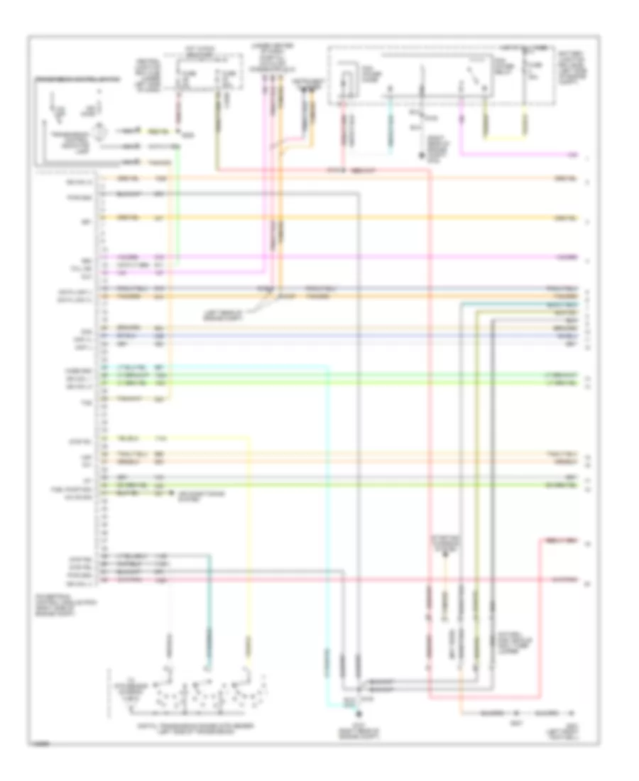
5.4L CNG, Engine Performance Wiring Diagram (1 of 5) for Ford Pickup Heritage F150 2004
List of elements for 5.4L CNG, Engine Performance Wiring Diagram (1 of 5) for Ford Pickup Heritage F150 2004:
- (left rear of engine compt)
- (not used)
- (right rear of engine compt) g102
- (under center of dash) (partial) datalink connector (dlc)
- A nca
- A/c on sig
- Air conditioning system
- Battery junction box (bjb) (left side of engine compt)
- C nca
- Case gnd
- Ccs
- Central junction box (cjb) (under left side of dash)
- Ckp (+)
- Ckp (-)
- Data link (+)
- Data link (-)
- Digital transmission range (dtr) sensor (left side of transmission)
- Dlc
- Dtr-tr1
- Dtr-tr2
- Dtr-tr4
- Fuel pump mon
- Fuse 30a
- Fuse 5a
- G107 (right rear of engine compt)
- G201 (left front footwell)
- Hot at all times
- Hot in run or start
- Iat
- Ign coil 1
- Ign coil 3
- Ign coil 5
- Ign coil 6
- Instrument cluster
- Maf
- Natural gas vehicle (ngv) timer jumper
- Nca
- O/d off
- Ohms
- Pcm power diode
- Pcm power relay
- Powertrain control module (pcm) (right side of engine compt)
- Pwr gnd
- R n
- S105
- S116
- S156
- S157
- S207
- S225
- Ss1
- Ss2
- Starting/ charging system
- Tan/red
- Tcil ind
- Tcs
- Tft
- To dtr sensor (diagram 5 of 5)
- Transmission control indicator lamp
- Transmission control switch
5.4L CNG, Engine Performance Wiring Diagram (2 of 5) for Ford Pickup Heritage F150 2004
List of elements for 5.4L CNG, Engine Performance Wiring Diagram (2 of 5) for Ford Pickup Heritage F150 2004:
- (left side of engine compt) speed control servo
- (left side of vehicle underbody)
- (near breakout to c192)
- (near breakout to c315) s302
- (top rear of eng)
- (under left side of dash) central junction box (cjb)
- Battery junction box (bjb) (left side of engine compt)
- C201d
- C220b
- C270b
- Crankshaft position sensor (lower front of engine)
- Front in-bed fuel tank valve (at fuel tank)
- Fuel gauge
- Fuse 15a
- G104 (left front of engine coompt)
- G107 (right rear of engine compt)
- Generic electronic module/ central timer module
- Inertia fuel shutoff (ifs) switch (behind right kick panel)
- Injection control pressure (icp) sensor (top of engine)
- Instrument cluster
- Intake air temperature (iat) sensor (on air intake)
- Midship fuel tank valve (under left side of vehicle)
- Nca
- Rear in-bed fuel tank valve (at fuel tank)
- Red
- Red/pnk
- S100
- S135
- S136
- S139
- S143
- S159 (left rear of eng compt)
- S199
- S301
- Throttle position sensor (tps) (on throttle body)
- Vss input
5.4L CNG, Engine Performance Wiring Diagram (3 of 5) for Ford Pickup Heritage F150 2004
List of elements for 5.4L CNG, Engine Performance Wiring Diagram (3 of 5) for Ford Pickup Heritage F150 2004:
- (near breakout to c110)
- 4r100 transmission
- Battery junction box (bjb) (left side of engine compt)
- Coast clutch solenoid
- Electronic pressure control solenoid
- Fuel pump relay
- Fuel rail cutoff valve (top of engine)
- Fuse 20a
- G102 (right rear of eng compt)
- Hot at all times
- Ignition coils
- Ignition transformer capacitor (on top left front of engine)
- Ignition transformer capacitor (on top right of engine)
- Nca
- Red
- Red red
- Red/pnk
- S117 (near breakout to c133)
- S140
- S153
- S161 (right side of eng compt)
- S162 (left side of eng compt)
- Shift solenoid
- Torque converter clutch solenoid
- Transmission fluid temperature sensor
5.4L CNG, Engine Performance Wiring Diagram (4 of 5) for Ford Pickup Heritage F150 2004
List of elements for 5.4L CNG, Engine Performance Wiring Diagram (4 of 5) for Ford Pickup Heritage F150 2004:
- (left side of vehicle underbody)
- Data (+)
- Data (-)
- Fuel gauge
- Fuel injectors
- Fuel press
- Fuel temp
- Ground
- Ignition
- Inj 1 input
- Inj 1 out
- Inj 2 input
- Inj 2 out
- Inj 3 input
- Inj 3 out
- Inj 4 input
- Inj 4 out
- Inj 5 input
- Inj 5 out
- Inj 6 input
- Inj 6 out
- Inj 7 input
- Inj 7 out
- Inj 8 input
- Inj 8 out
- Natural gas vehicle (ngv) fuel tank pressure sensor (at fuel tank)
- Natural gas vehicle (ngv) fuel tank temperature sensor (at fuel tank)
- Natural gas vehicle (ngv) module (right front of engine compt)
- Output shaft speed (oss) sensor (on left side of transmission)
- Power
- Red
- Red/pnk
- S127
- S129 (top right side of eng)
- S131
- S303 (center of vehicle underbody)
- Sig return
- Tan
- Tan/ red
- Tan/red
- Timer
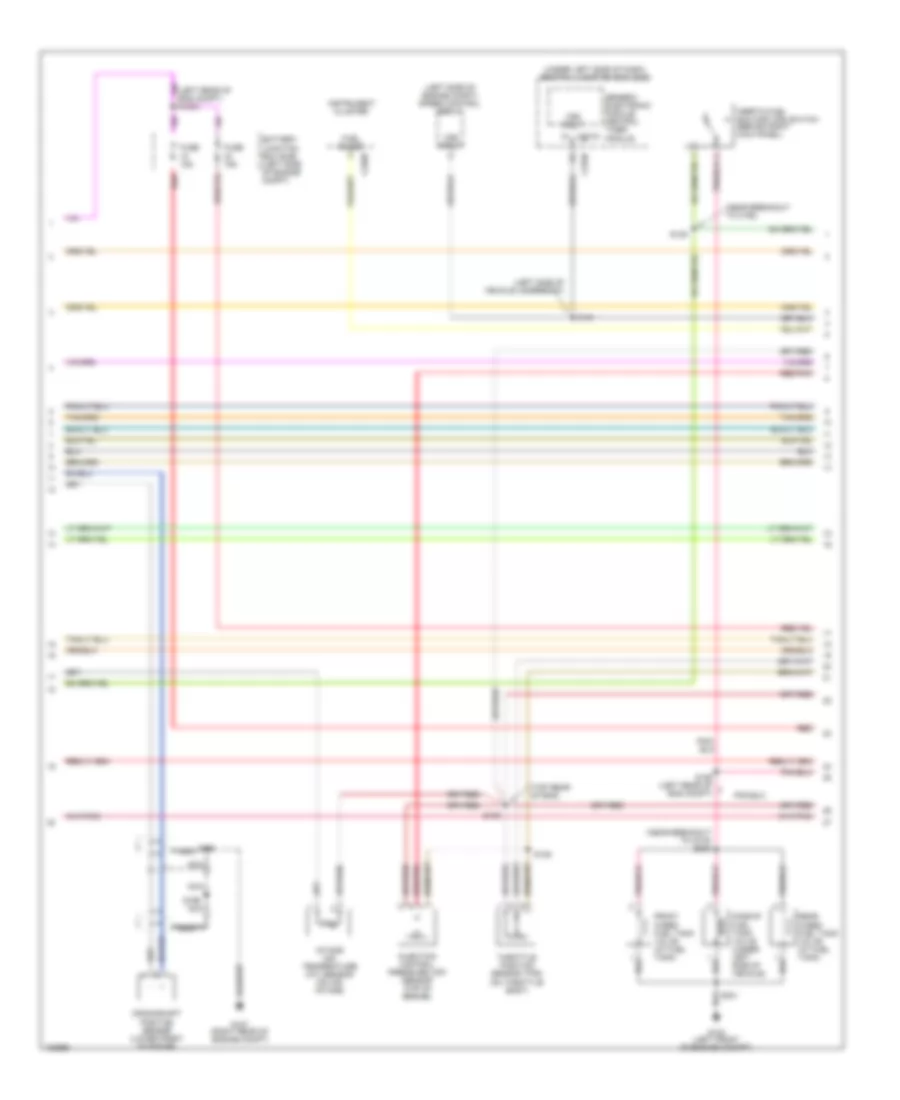
5.4L CNG, Engine Performance Wiring Diagram (5 of 5) for Ford Pickup Heritage F150 2004
List of elements for 5.4L CNG, Engine Performance Wiring Diagram (5 of 5) for Ford Pickup Heritage F150 2004:
- (left rear of eng compt)
- (left rear of engine compt)
- (left rear of trans) turbine shaft speed (tss) sensor
- (left side of dash) brake pedal position switch
- (near break- out to c110)
- (near breakout to c110)
- (near breakout to g101)
- (top rear of engine) cylinder- head temperature sensor
- 270 ohms
- 5v ref
- A/c clutch relay
- Battery junctioin box (bjb) (in left side of engine compt)
- Bpp switch
- C220a
- C270a
- C270b
- Camshaft position (cmp) sensor (front of left cylinder head)
- Central junction box (cjb) (under left side of dash)
- Cmp sensor
- Cyl head temp
- Digital transmission range (dtr) sensor (left side of transmission)
- Dtr-tr3a
- Eft sensor
- Epc sol
- From dtr sensor (diagram 1 of 5)
- Fuel cap off ind
- Fuel ctrl
- Fuel rail temperature sensor
- Fuse 5a
- G107 (right rear of engine compt)
- G201 (left front footwell)
- Heated oxygen sensor (ho2s) 11 (on engine exhaust pipe)
- Heated oxygen sensor (ho2s) 21 (on engine exhaust pipe)
- Ho2s (11)
- Ho2s (21)
- Ho2s sig (#11)
- Ho2s sig (21)
- Hot at all times
- Idle air control valve (on left side of intake manifold)
- Idle air ctrl
- Ign coil 2
- Ign coil 4
- Ign coil 7
- Ign coil 8
- Ind ctrl
- Inj pressure
- Instrument cluster
- Kap b(+)
- Maf sens in
- Mass air flow (maf) sensor (in air cleaner assembly)
- Nca
- Ngv module
- Not used
- Oss sensor
- Powertrain control module (pcm) (right side of engine compt)
- Pwr gnd
- Red
- Red/pnk
- S100
- S138
- S141
- S154
- S155
- S158
- Sig rtn
- Tcc sol
- Tp sens in
- Tss sensor
- Vpwr
- Vss (+)
- Wire terminates in harness
- Wot relay
5.4L SUPERCHARGED
5.4L Supercharged, Engine Performance Wiring Diagram (1 of 4) for Ford Pickup Heritage F150 2004
List of elements for 5.4L Supercharged, Engine Performance Wiring Diagram (1 of 4) for Ford Pickup Heritage F150 2004:
- (on air intake) intake air temperature (iat) sensor 2
- (right rear of engine compt) g101
- (right rear of engine compt) g107
- A/c system
- Accs
- Air cool rly
- Battery junction box (bjb) (left side of engine compt)
- C270b
- Case gnd
- Central junction box (bjb) (under left side of dash)
- Central junction box (cjb) (under left side of dash)
- Ckp(+)
- Ckp(-)
- Coil on plug
- Css
- Data link (+)
- Data link (-)
- Data link connector (partial) (under center of dash)
- Digital transmission range (dtr) sensor (left side of transmission)
- Dlc
- Evr ctrl
- Fuel h/l rly
- Fuel pump mon
- Fuse 15a
- Fuse 30a
- Fuse 5a
- G104 (left front of engine compartment)
- Ho2s sig (12)
- Hot at all times
- Hot in run or start
- Iat
- Ign coil 1
- Ign coil 3
- Ign coil 5
- Ign coil 6
- Ignition trans- former capacitor (top left front of engine)
- Ignition trans- former capacitor (top right of eng)
- Ind
- Instrument cluster system
- Ks sensor
- Maf
- Nca
- O/d off
- Pcm power diode
- Pcm power relay
- Powertrain control module (pcm) (right side of engine compt)
- Pwr gnd
- R n
- Red
- S100
- S1003 (near break- out to c140)
- S105
- S116
- S117 (near breakout to c133)
- S161 (right side of engine compt)
- S162 (left side of engine compt)
- Shift sol a
- Shift sol b
- Sol ctrl
- Supercharger bypass solenoid (rear of eng compt)
- Tcil
- Tcs
- Tft
- To dtr sensor (diagram 4 of 4)
- Tr1
- Tr2
- Tr4
- Transmission control switch (a/t)
5.4L Supercharged, Engine Performance Wiring Diagram (2 of 4) for Ford Pickup Heritage F150 2004
List of elements for 5.4L Supercharged, Engine Performance Wiring Diagram (2 of 4) for Ford Pickup Heritage F150 2004:
- (left front of engine compt)
- (left front of engine compt) g104
- (left side of vehicle underbody) s127
- (near break- out to c145) s151
- (near break- out to g101)
- (near break- out to g104)
- (right rear of engine compt) g102
- 87a
- Auxiliary relay box 1 (left side of engine comtp)
- Barometric absolute pressure sensor (rear of engine)
- Battery junction box (bjb) (left side of engine compt)
- Charge air cooler pump motor (front of engine compt)
- Charge air cooler pump relay
- Crankshaft position sensor (lower front of engine)
- Crash fuel shutoff relay
- Differential pressure feedback egr (dpfe) sensor (top rear of engine)
- Dropping resistor (left side of engine compt)
- Fuel pump (at fuel tank)
- Fuel pump high/low relay
- Fuel pump relay
- Fuel tank pressure sensor (top right side of eng)
- Fuse 20a
- G104
- G107 (right rear of engine compt)
- Hot at all times
- Inertia fuel shutoff (ifs) switch (behind right kick panel)
- Instrument cluster system
- Intake air temperature (iat) sensor 1 (top left side of eng)
- Nca
- Red
- Red/pnk
- S100
- S102
- S106
- S135 (top rear of engine)
- S136
- S137 (right rear of engine compt)
- S138
- S144
- S197 (rear of eng compt)
- S199
- Throttle position sensor (tps) (on throttle body)
- Turbine shaft speed (tss) sensor (left side of trans)
5.4L Supercharged, Engine Performance Wiring Diagram (3 of 4) for Ford Pickup Heritage F150 2004
List of elements for 5.4L Supercharged, Engine Performance Wiring Diagram (3 of 4) for Ford Pickup Heritage F150 2004:
- (left rear of engine compt)
- (left side of engine compt) speed control servo
- (left side of vehicle underbody)
- (near break- out to c110)
- (top right side of engine)
- (under left side of dash) central junction box (cjb)
- 4r100 transmission
- C201d
- Coast clutch solenoid
- Egr vacuum regulator solenoid (top rear of engine)
- Electronic pressure control solenoid
- Evap canister purge
- Fuel injectors
- Generic electronic module (gem)
- Idle air control (iac) valve (top center of engine)
- Output shaft speed (oss) sensor (left side of transmission)
- Red
- Red/pnk
- S129
- S131 (left of engine compt)
- S140
- S141
- S143
- S154
- S155
- Shift solenoid
- Tan
- Tan/ red
- Tan/red
- Torque converter clutch solenoid
- Transmission fluid temperature sensor
- Valve (left rear corner of engine compt)
- Vss input
5.4L Supercharged, Engine Performance Wiring Diagram (4 of 4) for Ford Pickup Heritage F150 2004
List of elements for 5.4L Supercharged, Engine Performance Wiring Diagram (4 of 4) for Ford Pickup Heritage F150 2004:
- (near break- out to c192)
- (near fuel tank)
- (on left side of engine compartment)
- (top rear of engine) cylinder- head temperature sensor
- (top right rear of engine) knock sensor
- (under left side of dash) brake pedal position switch
- 5v ref volt
- A/c clutch relay
- Bap sensor
- Battery junction box (bjb)
- Bpp sw
- Cam pos in
- Camshaft position sensor (on front of left cyl head)
- Canister vent
- Central junction box (cjb) (under left side of dash)
- Check engine
- Check fuel cap ind
- Compt)
- Cyl head temp
- Digital transmission range (dtr) sensor (left side of transmission)
- Dpfe sens
- Epc sol
- Evaporative emission (evap) canister vent valve
- From dtr sensor (diagram 1 of 4)
- Fuel cap ind
- Fuel inj 1
- Fuel inj 2
- Fuel inj 3
- Fuel inj 4
- Fuel inj 5
- Fuel inj 6
- Fuel inj 7
- Fuel inj 8
- Fuel pump ctrl
- Fuel tank press
- Fuse 5a
- G107 (right rear of engine
- G201 (in left front footwell)
- Heated oxygen sensor (ho2s) 11 (on engine exhaust pipe)
- Heated oxygen sensor (ho2s) 12 (on engine exhaust pipe)
- Heated oxygen sensor (ho2s) 21 (on engine exhaust pipe)
- Heated oxygen sensor (ho2s) 22 (on engine exhaust pipe)
- Ho2s htr (11)
- Ho2s htr (12)
- Ho2s htr (21)
- Ho2s htr (22)
- Ho2s sig (11)
- Ho2s sig (21)
- Ho2s sig (22)
- Hot at all times
- Hot in run
- Iac sol
- Ign coil 2
- Ign coil 4
- Ign coil 7
- Ign coil 8
- Instrument cluster
- Kap b(+)
- Knock sensor
- Maf sens in
- Mass air flow (maf) sensor (in air cleaner assembly)
- Nca
- Oss (+)
- Powertrain control module (pcm) (right side of engine compt)
- Pwr gnd
- Red
- Red/pnk
- S100
- S160
- S208
- S274
- Sig rtn
- Tan
- Tan/red
- Tcc sol
- Tp sens in
- Tr3a/cpp
- Tss
- Vapor valve
- Vpwr
- Vss (+)
- Wot relay
EXTERIOR LIGHTS
Back-up Lamps Wiring Diagram for Ford Pickup Heritage F150 2004
List of elements for Back-up Lamps Wiring Diagram for Ford Pickup Heritage F150 2004:
- A/t
- Anti-theft system
- Battery junction box (bjb) (in left side of engine compt)
- C270a
- Central junction box (cjb) (under left side of dash)
- Digital transmission range (dtr) sensor (on left side of transmission)
- Fuse 5 15a
- G104 (at left front of engine compt)
- Hot in run
- Left reversing lamp
- M/t
- Reversing lamps switch (on left side of transmission)
- Right reversing lamp
- S112
- S130 (engine control sensor harness, near breakout to c140)
- S401
- S405 (rear lamp connector wiring harness, near breakout to c405)
- Trailer tow reversing lamp relay
Exterior Lamps Wiring Diagram (1 of 2) for Ford Pickup Heritage F150 2004
List of elements for Exterior Lamps Wiring Diagram (1 of 2) for Ford Pickup Heritage F150 2004:
- (in right front footwell) g200
- Auxiliary relay box 4 (behind center of dash)
- Auxiliary relay box 5 (behind right center of dash)
- Brake pedal position switch (under left side of dash)
- C202a
- C220a
- C220b
- C270a
- C270b
- Central junction box (cjb) (under left side of dash)
- Driver side exterior rear view mirror
- Ends in harness
- Fuse 10a
- Fuse 20a
- Fuse 5a
- G103 (at right front side of vehicle exterior)
- G200 (in right front footwell)
- G203 (in right front footwell)
- G203 (in right front footwell)
- Hazard
- High mounted stop lamp
- Hot at all times
- Hot in run
- Indicator flasher relay
- Instrument cluster
- Left front park/ turn lamp
- Left mirror turn signal relay
- Left turn
- Left turn indicator
- Multi-function switch
- Nca
- Passenger side exterior rear view mirror
- Pnk
- Red
- Right front park/ turn lamp
- Right mirror turn signal relay
- Right turn
- Right turn indicator
- S104
- S202
- S204
- S220
- S221
- S228
- S246 (main wiring harness, near breakout to c192)
- S247 (main wiring harness, near breakout to c192)
- S500
- S501
- S600
- S911
- Trailer/camper adapter circuit
Exterior Lamps Wiring Diagram (2 of 2) for Ford Pickup Heritage F150 2004
List of elements for Exterior Lamps Wiring Diagram (2 of 2) for Ford Pickup Heritage F150 2004:
- (engine control sensor harness, at left rear side of engine compt) s149
- (engine control sensor harness, near breakout to c146) s148
- (main wiring harness, behind left side of dash) s224
- (rear lamp
- Auto
- Auxiliary relay box 3 (behind right center of dash)
- Battery junction box (bjb) (in left side of engine compartment)
- Battery junction box (bjb) (in left side of engine compt)
- C205b
- C274b
- Central security module (behind left side of dash)
- Connector wiring harness, at vehicle rear) s403
- Fuse 15a
- G104 (at left front of engine compt)
- Head
- Headlights system
- Hot at all times
- Left license plate lamp
- Left rear park/ stop/ turn lamp
- Main light switch
- Off
- Park
- Park lamp relay (w/ auto lamps)
- Right license plate lamp
- Right rear park/ stop/ turn lamp
- S115 (engine control sensor harness, at left rear of engine compt)
- S241 (w/ autolamps)
- S245 (main wiring harness, behind right side of dash)
- S401
- Trailer tow parking lamp relay
- Trailer/camper adapter circuit
Trailer/Camper Adapter Wiring Diagram for Ford Pickup Heritage F150 2004
List of elements for Trailer/Camper Adapter Wiring Diagram for Ford Pickup Heritage F150 2004:
- (engine control sensor harness, at left rear side of engine compt)
- (heavy duty)
- (in left side of engine compt)
- (main wiring harness, behind left side of dash)
- (trailer lamp feed wiring harness,
- Back-up lamps circuit
- Battery feed
- Battery junction box (bjb)
- Brake pedal position switch (under left side of dash)
- Breakout to c405)
- C202a
- C237 (on steering column)
- C270a
- C270b
- C439a trailer tow connector (heavy duty) (on rear of vehicle)
- C439b trailer tow connector (on rear of vehicle)
- Central junction box (cjb) (under left side of dash)
- Electronic brakes
- Exterior lamps circuit
- Fuse 10a
- Fuse 20a
- Fuse 30a
- G104 (at left front of engine compt)
- G200 (in right front footwell)
- G400 (at vehicle rear end)
- Ground
- Hot at all times
- Hot in run
- Illumination feed
- Left turn signal output
- Left turn/stop light
- Multi-function switch
- Near breakout to c405)
- Not used
- Parking
- Parking lights
- Red
- Reverse lights
- Right stop/turn light
- Right turn signal output
- Right turn/stop light
- S105
- S108
- S115 (engine control sensor harness, at left rear of engine compt)
- S120
- S130 (engine control sensor harness, near breakout to c140)
- S148 (engine control sensor harness, near breakout to c146)
- S149
- S201
- S221
- S231
- S406 (heavy duty) (trailer lamp feed wiring harness,
- S407 (heavy duty)
- S408 (heavy duty) (trailer lamp feed wiring harness, near
- S409
- Stoplight
- Trailer battery
- Trailer tow battery charge relay
- Trailer tow parking lamp relay
- Trailer tow reversing lamp relay
GROUND DISTRIBUTION
Ground Distribution Wiring Diagram (1 of 3) for Ford Pickup Heritage F150 2004
List of elements for Ground Distribution Wiring Diagram (1 of 3) for Ford Pickup Heritage F150 2004:
- (behind center of dash) auxiliary relay box 4
- (behind right side of dash) auxiliary relay box 2
- (engine control sensor & fuel charge harness, near breakout to c133)
- (w/o power equipment) right front door ajar switch
- 4.2l
- 4.2l, 5.4l
- 5.4l bi-fuel gas/lpg
- 5.4l super charged
- Adjustable pedal switch
- Air bag sliding contact
- Autolamp sensor
- Battery
- Blower motor relay
- Blower motor resistor
- Brake shift inter-lock
- C205a
- C205b
- C220a
- C294b
- C294c
- Camshaft position sensor
- Data link connector (dlc)
- Daytime running lamps (drl) relay 1
- Daytime running lamps (drl) relay 2
- Except 5.4l bi-fuel gas/lpg
- Except 5.4l super charged
- Four- wheel drive switch
- Function selector switch assembly
- G100 (at right rear of engine)
- G101 (at right rear of engine compartment)
- G105 (at right side of main chassis member)
- G107 (at right rear of engine compartment)
- G109 (at right rear of engine)
- G200 (in right front footwell)
- Indicator flasher relay
- Instrument cluster
- Left front door ajar switch
- Main light switch
- Mass air flow (maf) sensor
- Natural gas vehicle (ngv) module
- Nca
- Parking brake switch
- Powertrain control module (pcm)
- Radio
- S100 (engine control sensor harness, at right rear of engine compartment)
- S199
- S201 (main wiring harness, behind center of dash)
- S202 (main wiring harness, near breakout to auxiliary relay box 4)
- S203 (main wiring harness, behind right side of dash)
- S204 (main wiring harness, behind left side of dash)
- S4036 (in wiring harness, near breakout to c421)
- Shield
- Supercharged
- Temperature blend door actuator
- Trailer tow connector
- Transfer case relay module
- W/o power equipment
Ground Distribution Wiring Diagram (2 of 3) for Ford Pickup Heritage F150 2004
List of elements for Ground Distribution Wiring Diagram (2 of 3) for Ford Pickup Heritage F150 2004:
- (4.2l) intake manifold runner control (imrc) module
- (5.4l cng) fuel rail cutoff valve
- (in left side of engine compartment) auxiliary relay box 1
- (in left side of engine compartment) battery junction box (bjb)
- 4.2l, 5.4l cng
- 5.4l bi-fuel gas/cng
- 5.4l cng
- 5.4l supercharged
- 87a
- A/c clutch field coil
- A/c compressor clutch diode
- Abs control module
- Alternative fuel control module (afcm)
- Bi-fuel relay module
- Brake fluid level switch
- C439a
- C439b
- Charge air cooler pump motor
- Compuvalve module
- Digital transmission range (dtr) sensor
- Diode
- Dropping resistor
- Engine com- partment lamp
- Except 4.2l, 5.4l cng
- Except lightning
- Fog lamp relay
- Front in-bed fuel tank valve
- Fuel pump
- Fuel pump high/low relay
- Fuel rail cutoff valve
- G102 (at right rear of engine compartment)
- G103 (at right front side of vehicle exterior)
- G104 (at left front of engine compartment)
- G106 (at left front of engine compartment)
- G108 (at right front of engine compartment)
- G202 (in left front footwell)
- G400 (at vehicle rear end)
- G4001 (5.4l bi-fuel gas/lpg) (on front of left cylinder head)
- Harness, near breakout to c133)
- Heavy duty
- Horn
- Inertia fuel shutoff (ifs) switch
- Left front fog lamp
- Left front park/ turn lamp
- Left headlamp
- Left license plate lamp
- Left rear park/ stop/ turn lamp
- Left reversing lamp
- Lightning
- Midship fuel tank valve
- Nca
- Pcm power relay
- Radio
- Rear in-bed fuel tank valve
- Right front fog lamp
- Right front park/ turn lamp
- Right headlamp
- Right license plate lamp
- Right rear park/ stop/ turn lamp
- Right reversing lamp
- S102 (engine control sensor harness, at right rear of engine compartment)
- S105 (engine control sensor harness, at left side of engine compartment)
- S106 (engine control sensor harness, near breakout to g104)
- S175 (engine control sensor harness, at right front of engine compartment)
- S400 (except cng: tail lamps wiring harness, under center rear of vehicle) (cng: taillight wiring harness, near breakout to c315)
- S401 (rear lamp connector wiring harness, at vehicle rear)
- S409 (at vehicle rear)
- Sensor harness, near breakout to g103)
- Speed control servo
- Tank valve
- Trailer tow battery charge relay
- Trailer tow connector
- Trailer tow parking lamp relay
- Trailer tow reversing lamp relay
- W/ mp3 player
- W/o mp3 player
- Windshield washer pump motor
- Windshield wiper motor
Ground Distribution Wiring Diagram (3 of 3) for Ford Pickup Heritage F150 2004
List of elements for Ground Distribution Wiring Diagram (3 of 3) for Ford Pickup Heritage F150 2004:
- (behind right center of dash) auxiliary relay box 5
- (regular cab, super cab)
- (under left side of dash) central junction box (cjb)
- 5.4l cng
- 5.4l supercharged
- 87a
- Belt minder module
- Brake pedal position switch
- C2013b
- C201a
- C220b
- C270b
- C274a
- C274b
- Cargo lamp 1
- Cargo lamp 2
- Central security module
- Central timer module (ctm)
- Driver side door lock switch
- Driver side exterior rear view mirror
- Except 5.4l cng
- Except 5.4l supercharged
- Except super cab
- Exterior rear view mirror switch
- Front cigar lighter
- Front interior/ map lamps assembly
- Fuel pump
- G201 (in left front footwell)
- G203 (in right front footwell)
- Generic electronic module (gem)
- Harness, near breakout to g202)
- High mounted stoplamp
- Instrument cluster
- Interior lamp
- Key pad switch assembly
- Left front door ajar switch
- Left mirror turn signal relay
- Left power seat switch
- Left vanity mirror lamp
- Master window adjust switch
- Natural gas vehicle (ngv) module
- Nca
- Ngv timer jumper
- Of instrument cluster) (manual a/c: main wiring harness, near breakout to c268)
- One-touch window relay
- Overhead console
- Parking brake switch
- Passenger air bag deactivation (pad) switch
- Passenger side door lock switch
- Passenger side exterior rear view mirror
- Passive anti-theft transceiver module
- Power point
- Restraints control module
- Right front door ajar switch
- Right mirror turn signal relay
- Right vanity mirror lamp
- S500 (body main wiring harness, in driver door)
- S501 (body main wiring harness, near steering column)
- S600 (body main wiring harness, in passenger door)
- S911 (high mounted stoplight wiring harness, in roof panel, center of vehicle)
- Safety belt buckle switch
- Super cab
- Super cab, regular cab w/ map lamps
- Super cab, regular cab w/o map lamps
- Super cab, w/ power seats
HEADLIGHTS
Autolamps & Fog Lamps Wiring Diagram, with DRL for Ford Pickup Heritage F150 2004
List of elements for Autolamps & Fog Lamps Wiring Diagram, with DRL for Ford Pickup Heritage F150 2004:
- (at front right side of vehicle exterior)
- (engine control sensor harness, near breakout to g104) s114
- (engine control sensor harness, near breakout to g104) s147
- (main wiring
- (main wiring harness, under dash, near steering column) s218
- Auto
- Autolamp out
- Autolamp sensor (on top right side of dash)
- Auxiliary relay box 2 (behind right side of dash)
- Auxiliary relay box 3 (behind right center of dash)
- Battery junction box (bjb) (in left side of engine compt)
- C1322
- C1323
- C152
- C162
- C202b
- C205b
- C220a
- C270a
- C270b
- C274b
- Central junction box (cjb) (under left side of dash)
- Central security module (behind left side of dash)
- Daytime running lamps (drl) relay 1
- Daytime running lamps (drl) relay 2
- Daytime running lamps resistor (in left front of engine compt)
- Except lightning lightning
- Exterior lights system
- Fog lamp relay
- Fog lamp switch
- Fog on indicator
- Fuse 10a
- Fuse 15a
- Fuse 20a
- Fuse 30a
- Fuse 5a
- G103
- G104 (at front left of engine compt)
- G200 (in right front footwell)
- Ground
- Harness, under dash, near steering column) s241
- Head
- Headlamp relay
- Hi-beam indicator
- Hot at all times
- Hot in run
- Hot in start or run
- Ignition
- Instrument cluster
- Left front fog lamp
- Left headlamp
- Lightning except lightning
- Main light switch
- Multi- function switch
- Off
- Park
- Park lamp relay
- Pass
- Relay ground
- Right front fog lamp
- Right headlamp
- S104
- S105
- S109
- S203
- S204
- S212
- S222
- S225
- S245 (main wiring harness, behind right side of dash)
- Under dash, near steering column)
Autolamps & Fog Lamps Wiring Diagram, without DRL for Ford Pickup Heritage F150 2004
List of elements for Autolamps & Fog Lamps Wiring Diagram, without DRL for Ford Pickup Heritage F150 2004:
- (engine control sensor harness, near breakout to g104) s114
- (engine control sensor harness, near breakout to g104) s147
- (main wiring harness, under dash, near steering column) s218
- (main wiring harness, under dash, near steering column) s241
- Auto
- Autolamp out
- Autolamp sensor (on top right side of dash)
- Auxiliary relay box 3 (behind right center of dash)
- Battery junction box (bjb) (in left side of engine compt)
- C1322 c152
- C1323 c162
- C152 c1322
- C162 c1323
- C202b
- C205b
- C220a
- C270a
- C270b
- C274b
- Central junction box (cjb) (under left side of dash)
- Central security module (behind left side of dash)
- Except lightning lightning
- Exterior lights system
- Fog lamp relay
- Fog lamp switch
- Fog on indicator
- Fuse 10a
- Fuse 15a
- Fuse 20a
- Fuse 30a
- Fuse 5a
- G103 (at front right side of vehicle exterior)
- G104 (at front left of engine compt)
- G200 (in right front footwell)
- Ground
- Head
- Headlamp relay
- Hi-beam indicator
- Hot at all times
- Hot in start or run
- Ignition
- Instrument cluster
- Left front fog lamp
- Left headlamp
- Lightning except lightning
- Main light switch
- Multi- function switch
- Off
- Park
- Park lamp relay
- Pass
- Relay ground
- Right front fog lamp
- Right headlamp
- S104
- S105
- S109
- S203
- S204
- S212
- S225
- S244 (main wiring harness, under dash, near steering column)
- S245 (main wiring harness, behind right side of dash)
Headlamps & Fog Lamps Wiring Diagram, with DRL for Ford Pickup Heritage F150 2004
List of elements for Headlamps & Fog Lamps Wiring Diagram, with DRL for Ford Pickup Heritage F150 2004:
- (engine control sensor harness, near breakout to g104) s114
- (engine control sensor harness, near breakout to g104) s147
- (under left side of dash)
- Auxiliary relay box 2 (behind right side of dash)
- Battery junction box (bjb) (in left side of engine compartment)
- C1322
- C1323
- C152
- C162
- C202b
- C205b
- C220a
- C270a
- C270b
- Central junction box (cjb)
- Daytime running lamps (drl) relay 1
- Daytime running lamps (drl) relay 2
- Daytime running lamps resistor (in left front of engine compt)
- Except lightning
- Fog lamp relay
- Fog lamp switch
- Fog on indicator
- Fuse 10a
- Fuse 15a
- Fuse 20a
- Fuse 30a
- Fuse 5a
- G103 (at front right side of vehicle exterior)
- G104 (at front left of engine compt)
- G200 (in right front footwell)
- Head
- Hi-beam indicator
- Hot at all times
- Hot in run
- Instrument cluster
- Left front fog lamp
- Left headlamp
- Lightning
- Main light switch
- Multi- function switch
- Off
- Park
- Pass
- Right front fog lamp
- Right headlamp
- S104
- S105
- S109
- S203
- S204
- S212
- S218 (main wiring harness, under dash, near steering column)
- S222
- S244 (main wiring harness, under dash, near steering column)
Headlamps & Fog Lamps Wiring Diagram, without DRL for Ford Pickup Heritage F150 2004
List of elements for Headlamps & Fog Lamps Wiring Diagram, without DRL for Ford Pickup Heritage F150 2004:
- (engine control sensor harness, near breakout to g104) s114
- (engine control sensor harness, near breakout to g104) s147
- (under left side of dash)
- Battery junction box (bjb) (in left side of engine compt)
- C1322 c152
- C1323 c162
- C152 c1322
- C162 c1323
- C202b
- C205b
- C220a
- C270a
- C270b
- Central junction box (cjb)
- Except lightning lightning
- Fog lamp relay
- Fog lamp switch
- Fog on indicator
- Fuse 10a
- Fuse 15a
- Fuse 20a
- Fuse 30a
- Fuse 5a
- G103 (at front right side of vehicle exterior)
- G104 (at front left of engine compt)
- G104 g104 (at front left of engine compt)
- G200 (in right front footwell)
- G200 g200 (in right front footwell)
- Head
- Hi-beam indicator
- Hot at all times
- Instrument cluster
- Left front fog lamp
- Left headlamp
- Lightning except lightning
- Main light switch
- Multi- function switch
- Off
- Park
- Pass
- Right front fog lamp
- Right headlamp
- S104
- S105
- S109
- S204
- S212
- S218 (main wiring harness, under dash, near steering column)
- Steering column)
HORN
Horn Wiring Diagram for Ford Pickup Heritage F150 2004
List of elements for Horn Wiring Diagram for Ford Pickup Heritage F150 2004:
- Air bag sliding contact (on steering column)
- Battery junction box (bjb) (in left side of engine compartment)
- C218b
- C274a
- Central security module (behind left side of dash)
- Fuse 7 20a
- G103 (at front right side of vehicle exterior)
- High pitch horn
- Horn
- Horn (at right front of vehicle)
- Horn relay
- Hot at all times
- Low pitch horn
- Nca
- Rest
- S104
- Speed control servo (in left side of engine compartment)
- Steering wheel/ speed control switch
INSTRUMENT CLUSTER
Instrument Cluster Wiring Diagram for Ford Pickup Heritage F150 2004
List of elements for Instrument Cluster Wiring Diagram for Ford Pickup Heritage F150 2004:
- (conn a)
- (conn b)
- (ctm)
- (engine control sensor harness, near breakout to c140) s170
- (gem)
- (in left front footwell) g200
- (in right front footwell)
- (main wiring harness, behind left side of dash)
- (w/o power equipment) s203
- (w/o power equipment) s252
- 4wd high ind
- 4wd low ind
- 5.4l cng
- 5.4l supercharged
- A10
- A11
- A12
- A13
- A14
- A16
- A17
- A18
- A19
- A20
- Abs control module (in left side of engine compt)
- Abs ind
- Air bag ind
- Anti-lock brakes system
- B10
- B14
- B15
- B17
- B22
- Bias ckt
- Brake fluid level switch (on brake fluid reservoir)
- C201a
- C201c
- C220a
- C220b
- C2224
- C270a
- C270b
- Central junction box (cjb) (under left side of dash)
- Charge ind
- Check engine indicator
- Check fuel cap indicator
- Computer data lines system
- Cruise control system
- Cruise ind
- Door ajar ind
- Except 5.4l cng
- Except 5.4l supercharged
- Exterior lights system
- Fuel pump (at fuel tank)
- Fuel pump module
- Fuse 30a
- Fuse 5a
- G104 (at left front of engine compt)
- G200
- G201 (in left front footwell)
- G203 (in right front footwell)
- G203 (w/ power equipment) g200 (w/o power equipment)
- Generic electronic module/ central timer module (behind left side of dash)
- Headlights system
- Hi beam ind
- Hot at all times
- Hot in run
- Hot in start or run
- Illumination
- Instrument cluster
- Interior lights system
- Left front door ajar switch (in left front door)
- Left turn ind
- Low brake fluid level/ park brake ind
- Low fuel ind
- Low oil pressure ind
- Micro- processor
- Microprocessor
- Natural gas vehicle (ngv) module (on right front of engine compt)
- Nca
- Oil pressure switch (on left front of engine)
- Parking brake switch (near left kick panel)
- Passive anti-theft transceiver module (behind left center of dash)
- Powertrain control module (pcm) (on right side of engine compt)
- Restraints control module (behind lower center of dash)
- Right front door ajar switch (in right front door)
- Right turn ind
- S106
- S204
- S207
- S232
- S236
- S237
- S252 (w/o power equipment)
- S265
- S268 (main wiring harness, behind left side of dash)
- S501 (w/ power equipment)
- S600 (w/ power equipment)
- Safety belt ind
- Starting/charging system
- W/ power equipment
- W/o power equipment
- Warning system
Overhead Console Wiring Diagram for Ford Pickup Heritage F150 2004
List of elements for Overhead Console Wiring Diagram for Ford Pickup Heritage F150 2004:
- Ambient air temperature sensor (in right side of engine compt)
- C201d
- C270b
- Central junction box (cjb) (under left side of dash)
- Fuse 10a
- G201 (in left front footwell)
- G203 (in right front footwell)
- Generic electronic module (gem) (behind left side of dash)
- Gnd
- Hot in run
- Illumination
- Interior lights system
- Nca
- Overhead console (in center front of roof)
- S208
- S304
- S311
- Sig rtn
- Vpwr
- Vref
- Vss
INTERIOR LIGHTS
Courtesy Lamps Wiring Diagram for Ford Pickup Heritage F150 2004
List of elements for Courtesy Lamps Wiring Diagram for Ford Pickup Heritage F150 2004:
- engine compartment lamp
- (ctm)
- (in right front footwell)
- (near breakout to c919) s900
- (right seat belt retractor switch harness, near breakout to c919) s904
- (w/ power equipment)
- (w/ power equipment) (w/o power equipment)
- (w/o power equipment)
- Battery saver input
- Battery saver relay
- C201a
- C201d
- C205a
- C2224
- C270a
- C270b
- Cargo lamp 1
- Cargo lamp 2
- Central junction box (cjb) (under left side of dash)
- Door ajar input
- Front interior/ map lamps assembly
- Fuse 15a
- G102 (at right rear of engine compt)
- G200 (in right front footwell)
- G200 g203
- G203 (in right front footwell)
- Generic electronic module (gem) (or central timer module (ctm)) (behind left side of dash) (gem)
- Hot at all times
- Interior lamp
- Interior lamp relay
- Interior lamp relay input
- Interior lamp switch
- Left front door ajar switch (in left front door)
- Left vanity mirror lamp
- Main light switch
- Map lamp 1
- Map lamp 2
- Nca
- Overhead console
- Pnk
- Regular cab w/0 reading lamps
- Right front door ajar switch (in right front door)
- Right vanity mirror lamp
- S102
- S204
- S240 (main wiring harness, near glove box)
- S304
- S501 s252
- S600 s203
- S911
- W/ reading lamps
Instrument Illumination Wiring Diagram for Ford Pickup Heritage F150 2004
List of elements for Instrument Illumination Wiring Diagram for Ford Pickup Heritage F150 2004:
- (w/ autolamps)
- Adjustable pedal switch
- Air bag sliding contact (on steering column)
- Auto
- Battery junction box (bjb) (in left side of engine compt)
- C205a
- C205b
- C218b
- C220a
- C220b
- C270a
- C270b
- C294c
- Central junction box (cjb) (under left side of dash)
- Exterior lights system
- Four-wheel drive switch
- Function selector switch assembly
- Fuse 15a
- Fuse 5a
- G200 (in right front footwell)
- G202 (in left front footwell)
- G203 (in right front footwell)
- Head
- Hot at all times
- Illum
- Instrument cluster (6 bulbs)
- Main light switch
- Microprocessor
- Nca
- Of dash)
- Off
- Overhead console (in center front of roof)
- Park
- Radio
- S201
- S202
- S203
- S204
- S241
- S304
- Steering wheel/ speed control switch
- W/ mp3 player
- W/o mp3 player
POWER DISTRIBUTION
Power Distribution Wiring Diagram (1 of 4) for Ford Pickup Heritage F150 2004
List of elements for Power Distribution Wiring Diagram (1 of 4) for Ford Pickup Heritage F150 2004:
- (engine control sensor harness, at left front of engine compt) s171
- (engine control sensor harness, at left rear of engine compt) s109
- (main wiring harness, near steering column) s212
- (main wiring harness, under dash, near steering column) (w/ autolamps) s241
- (starter motor relay & battery ground harness, at right front of engine compt) s1001
- 5.4l
- A/c clutch relay
- Abs control module
- Auxiliary relay box 3 (behind right center of dash)
- Battery
- Battery junction box (bjb) (in left side of engine compt)
- Bi-fuel gas/lpg
- Bi-fuel power relay
- Bi-fuel relay module (in bi- fuel relay module)
- C102a
- C202b
- C205b
- C274b
- Central security module
- Charge air cooler pump relay
- Cold start heater relay
- Compuvalve module
- Daytime running lamps resistor
- Fog lamp relay
- From a fuse 8 (diagram 1 of 4)
- Fuse 10a
- Fuse 15a
- Fuse 20a
- Fuse 30a
- Fuse 3a
- Fuse 50a
- Generator
- Headlamp relay (w/ autolamps)
- Horn relay
- Main light switch
- Multi- function switch
- Nca
- Park lamp relay (w/ autolamps)
- Power point (at center of dash)
- Red
- S1002 (starter motor relay & battery ground harness, at right front of engine compt)
- S108 (engine control sensor harness, at left rear of engine compt)
- Starter motor
- Starter relay
- To fuse 104 (diagram 2 of 4)
- To fuse 9 (diagram 1 of 4)
- To splice s205 (diagram 3 of 4)
- Trailer tow battery charge relay
- Trailer tow parking lamp relay
- Trailer tow reversing lamp relay
Power Distribution Wiring Diagram (2 of 4) for Ford Pickup Heritage F150 2004
List of elements for Power Distribution Wiring Diagram (2 of 4) for Ford Pickup Heritage F150 2004:
- (engine control sensor harness, at left rear of engine compt) s112
- (engine control sensor harness, near breakout to c140) s113
- (main wiring harness, at center of dash) s213
- (main wiring harness, behind left side of dash) s222
- (main wiring harness, under dash, near steering column) s265
- (not used)
- 5.4l supercharged
- A/t
- Acc
- Accessory delay relay
- Adjustable pedal switch
- Auxiliary relay box 2 (behind right side of dash)
- Auxiliary relay box 3 (behind right center of dash)
- Auxiliary relay box 4 (behind center of dash)
- Battery junction box (bjb) (in left side of engine compt)
- Blower motor relay
- Brake pressure switch
- Brake shift interlock
- C201d
- C220a
- C270a
- C270b
- C294a
- Central junction box (cjb) (under left side of dash)
- Daytime running lamps (drl) relay 1
- Digital trans- mission range (dtr) sensor
- Esof
- Except supercab
- From b fuse 3 (diagram 1 of 4)
- Fuel pump relay
- Function selector switch assembly
- Fuse 15a
- Fuse 20a
- Fuse 2a
- Fuse 30a
- Fuse 40a
- Fuse 50a
- Fuse 5a
- Generic electronic (gem) module or central timer module (ctm)
- Ignition switch
- Instrument cluster
- Left power seat switch
- Lock
- M/t
- Mechanical shift on the fly (msof) relay
- Msof
- Nca
- Off
- Pcm power relay
- Radio
- Red
- Reversing lamps switch
- Run
- S214 (main wiring harness, near breakout to c263)
- S215 (main wiring harness, near steering column)
- Speed control servo
- Start
- Start start
- Supercab
- Temperature blend door actuator
- To fuse 1 (diagram 3 of 4)
- To fuse 22 (diagram 4 of 4)
- To fuse 29 (diagram 3 of 4)
- To splice s227 (diagram 4 of 4)
- Trailer tow connector
- Transfer case electric clutch relay
- Transfer case relay module
- W/ mp3 player
- W/o mp3 player
- Windshield washer relay
- Windshield wiper motor
- Wiper high/ low relay
- Wiper run/park relay
Power Distribution Wiring Diagram (3 of 4) for Ford Pickup Heritage F150 2004
List of elements for Power Distribution Wiring Diagram (3 of 4) for Ford Pickup Heritage F150 2004:
- (5.4l bi-fuel gas/cng)
- (body main wiring harness, near breakout to c260) s220
- (engine control sensor & fuel charge harness, at left side of engine compt) s162
- (engine control sensor & fuel charge harness, at right side of engine compt) s161
- (engine control sensor & fuel charge wiring harness, near breakout to c133) s117
- (engine control sensor harness, near breakout to c140) s116
- (main wiring harness, behind center of dash) s289
- (main wiring harness, behind left side of dash) s225
- (main wiring harness, behind left side of dash) s236
- (main wiring harness, under dash, near steering column) s237
- (main wiring harness, under dash, near steering column) s274
- 4.2l
- 5.4l supercharged
- Autolamp sensor
- Auxiliary relay box 1 (in left side of engine compt)
- Auxiliary relay box 4 (behind center of dash)
- Auxiliary relay box 5 (behind right center of dash)
- Battery junction box (bjb) (in left side of engine compt)
- Battery saver relay
- Belt minder module
- Bi-fuel power relay
- Brake pedal position switch
- Brake pressure switch
- C2013b
- C201d
- C220a
- C270a
- C270b
- C274a
- Central junction box (cjb) (under left side of dash)
- Central security module
- Coil on plug (cop) 1
- Coil on plug (cop) 2
- Coil on plug (cop) 3
- Coil on plug (cop) 4
- Coil on plug (cop) 5
- Coil on plug (cop) 6
- Coil on plug (cop) 7
- Coil on plug (cop) 8
- Data link connector (dlc)
- Except 4.2l
- Exterior rear view mirror switch
- From fuse 103 (diagram 2 of 4)
- From ignition switch (diagram 2 of 4)
- From power point (diagram 1 of 4)
- Front cigar lighter
- Fuel pump cutoff relay
- Fuse 15a
- Fuse 20a
- Fuse 30a
- Fuse 5a
- G203 (in right front footwell)
- Generic electronic module (gem) or central timer module (ctm)
- Ignition coil
- Ignition transformer capacitor 1
- Ignition transformer capacitor 2
- Indicator flasher relay
- Instrument cluster
- Interior lamp relay
- Left mirror turn signal relay
- Natural gas vehicle (ngv) module (5.4l cng)
- Nca
- Off
- Passive anti-theft transceiver module
- Pcm power diode
- Pcm power relay
- Powertrain control module (pcm)
- Radio
- Right mirror turn signal relay
- S158
- S205
- S221 (main wiring harness, under dash, near steering column)
- Transmission control switch
- W/ mp3 player
- W/o mp3 player
Power Distribution Wiring Diagram (4 of 4) for Ford Pickup Heritage F150 2004
List of elements for Power Distribution Wiring Diagram (4 of 4) for Ford Pickup Heritage F150 2004:
- (engine control sensor harness, near breakout to c140) s120
- (main wiring harness, behind left side of dash) s227
- (main wiring harness, under dash, near steering column) s228
- (not used)
- (right seat belt retractor switch harness, at right "b" pillar) s311
- 4x2 center axle disconnect solenoid
- 4x4 center axle disconnect solenoid
- Abs control module
- Auxiliary relay box 3 (behind right center of dash)
- Auxiliary relay box 4 (behind center of dash)
- Battery junction box (bjb) (in left side of engine compt)
- C201d
- C207b
- C270b
- C294a
- Central junction box (cjb) (under left side of dash)
- Clutch pedal position switch
- Digital transmission range (dtr) sensor
- Esof
- From fuse 21 (diagram 2 of 4)
- From ignition switch (diagram 2 of 4)
- Function selector switch assembly
- Fuse 10a
- Fuse 5a
- Generic electronic module (gem) or central timer module (ctm)
- Indicator flasher relay
- M/t
- Mechanical shift on the fly (msof) relay
- Msof
- Nca
- Overhead console
- Passenger air bag deactivation (pad) switch
- Powertrain control module (pcm)
- Radio
- Restraints control module
- Tan/red
- Trailer tow battery charge relay
- Transfer case electric clutch relay
POWER DOOR LOCKS
Power Door Locks Wiring Diagram for Ford Pickup Heritage F150 2004
List of elements for Power Door Locks Wiring Diagram for Ford Pickup Heritage F150 2004:
- (behind left side of dash) s601
- (in right front footwell)
- (in right front footwell) g203
- (near center of dash) data link connector (dlc)
- (near steering column) s234
- 1/2
- 3/4
- 5/6
- 7/8
- 9/0
- Ajar out
- Battery
- Battery junction box (bjb) (in left side of engine compt)
- Bpp sw in
- Brake pedal position switch (under left side of dash)
- C201a
- C201b
- C270b
- C274a
- C274b
- Central junction box (cjb) (under left side of dash)
- Central security module (behind left side of dash)
- Door ajar
- Doors lock
- Doors unlock
- Dr ajar sw
- Driver side door lock switch
- Exterior lights system
- Fuse 15a
- Fuse 5a
- G201 (in left front footwell)
- G203
- G203 (in right front footwell)
- Generic electronic module (gem) (behind left side of dash)
- Ground
- Horn
- Horns system
- Hot at all times
- Hot in start or run
- Illum entry
- Illum in
- Interior lights system
- Iso
- Key pad common
- Key pad switch assembly
- Keypad illum
- Left front door ajar switch (in left front door)
- Left front door lock actuator (in left front door)
- Lf out
- Lft
- Lock
- Lock in/out
- Nca
- Passenger side door lock switch
- Red
- Relay ctrl
- Reverse
- Right front door ajar switch (in right front door)
- Right front door lock actuator (in right front door)
- S208
- S225
- S229 (main wiring harness, behind left side of dash)
- S235 (body main wiring harness, near steering column)
- S274
- S297 (main wiring harness, behind left side of dash)
- S500
- S501
- S600
- Unlk
- Unlock in/out
- Vpwr
POWER MIRRORS
Power Mirrors Wiring Diagram for Ford Pickup Heritage F150 2004
List of elements for Power Mirrors Wiring Diagram for Ford Pickup Heritage F150 2004:
- C270a
- Central junction box (cjb) (under left side of dash)
- Down
- Driver side exterior rear view mirror
- Exterior lights system
- Exterior rear view mirror switch
- Fuse 5a
- G203 (in right front footwell)
- Hot at all times
- Left
- Left mirror
- Left/ right
- Nca
- Passenger side exterior rear view mirror
- Pnk
- Red
- Right
- Right mirror
- S220
- S500
- S503 (body main wiring harness, in driver door)
- Up/ down m
POWER SEATS
Adjustable Pedal Wiring Diagram for Ford Pickup Heritage F150 2004
List of elements for Adjustable Pedal Wiring Diagram for Ford Pickup Heritage F150 2004:
- Adjustable pedal motor (behind lower left side of dash)
- Adjustable pedal switch
- Battery junction box (bjb) (in left side of engine compt)
- Fuse 30a
- Fwd
- G200 (in right front footwell)
- Hot at all times
- Illum
- Interior lights system
- Nca
- Red
- Rwd
- S204
- S298
Driver Power Seat Wiring Diagram for Ford Pickup Heritage F150 2004
List of elements for Driver Power Seat Wiring Diagram for Ford Pickup Heritage F150 2004:
- (super cab) (except super cab)
- Battery junction box (bjb) (in left side of engine compt)
- Entire seat
- Forward/rearward
- Front of seat
- Fuse 112 30a
- Fwd
- G203 (in right front footwell)
- Hot at all times
- Left power seat motor assembly (under driver seat)
- Left power seat switch
- Nca
- Rear of seat
- Rwd
- S298
- S304
- Super cab except super cab
- Up/down front
- Up/down rear
POWER WINDOWS
Power Windows Wiring Diagram for Ford Pickup Heritage F150 2004
List of elements for Power Windows Wiring Diagram for Ford Pickup Heritage F150 2004:
- (in right front footwell)
- 87a
- Accessory delay relay
- Batt saver
- Battery junction box (bjb) (in left side of engine compartment)
- Battery saver relay
- C201d
- C270a
- C270b
- Central junction box (cjb) (under left side of dash)
- Down sw input
- Driver side door lock switch
- Driver side front power window motor
- Fuse 15a
- Fuse 30a
- Fuse 50a
- G203
- G203 (in right front footwell)
- Generic electronic module (gem)
- Ground
- Hot at all times
- Late production
- Left switch
- Master window adjust switch
- Nca
- One tch dn hi
- One tch dn lo
- One- touch down
- One- touch window relay
- Otd sw input
- Passenger side door lock switch
- Passenger side front power window motor
- Passenger side window adjust switch
- Power tops system
- Right switch
- S205
- S230 (main wiring harness, near glove box)
- S248 (body main wiring harness, behind left side of dash)
- S500
- S600
RADIO
MP3 Player Wiring Diagram for Ford Pickup Heritage F150 2004
List of elements for MP3 Player Wiring Diagram for Ford Pickup Heritage F150 2004:
- (in left front footwell) g202
- Antenna
- C270a
- Central junction box (cjb) (under left side of dash)
- Fuse 15a
- Fuse 5a
- Fused ignition
- Ground
- Hot at all times
- Hot in run or acc
- Illumination
- Interior lights system
- L front spkr (+)
- L front spkr (-)
- L rear spkr (+)
- Left front speaker
- Left rear speaker
- Nca
- Power
- R front spkr (+)
- R front spkr (-)
- R rear spkr (+)
- R rear spkr (-)
- Radio (cdx6)
- Right front speaker
- Right rear speaker
- Twisted pair
Radio Wiring Diagram for Ford Pickup Heritage F150 2004
List of elements for Radio Wiring Diagram for Ford Pickup Heritage F150 2004:
- (in right front footwell) g200
- Antenna
- C270a
- C270b
- Central junction box (cjb) (under left side of dash)
- Engine controls system
- Fuse 15a
- Fuse 5a
- Fused ignition
- G202 (in left front footwell)
- Ground
- Hot at all times
- Hot in run or acc
- Hot in start
- Illumination
- Interior lights system
- L front spkr (+)
- L front spkr (-)
- L rear spkr (+)
- L rear spkr (-)
- Left front speaker
- Left rear speaker
- Nca
- Power
- R front spkr (+)
- R front spkr (-)
- R rear spkr (+)
- R rear spkr (-)
- Radio (cassette, cdx6, dual media)
- Right front speaker
- Right rear speaker
- S203
- Twisted pair
SHIFT INTERLOCK
Shift Interlock Wiring Diagram for Ford Pickup Heritage F150 2004
List of elements for Shift Interlock Wiring Diagram for Ford Pickup Heritage F150 2004:
- Brake pedal position switch (under left side of dash)
- Brake shift interlock (on steering column)
- C270a
- C270b
- Central junction box (cjb) (under left side of dash)
- Fuse 15 5a
- Fuse 6 5a
- G200 (in right front footwell)
- G201 (in left front footwell)
- Hot at all times
- Hot in run
- Microprocessor
- S204
- S208
- S265
- S274
- S297 (main wiring harness, behind left side of dash)
STARTING/CHARGING
Charging Wiring Diagram for Ford Pickup Heritage F150 2004
List of elements for Charging Wiring Diagram for Ford Pickup Heritage F150 2004:
- 3g generator
- Acc
- Battery (at right front of engine compt)
- Battery junction box (bjb) (in left side of engine compt)
- C102a
- C102b
- C220a
- C270b
- Central junction box (cjb) (under left side of dash)
- Charge indicator
- Fuse 2oa
- Fuse 30a
- Fuse 40a
- G100 (at right rear of engine)
- G105 (at right side of main chassis member)
- G109 (at right rear of engine)
- Generator (on top front of engine)
- Ignition switch
- Instrument cluster
- Lock
- Off
- Power distribution system
- Red
- Run
- S1001
- S1002
- S214
- S237
- Start
- Starter motor (on lower left side of engine)
- Starter relay (in right rear of engine compt)
Starting Wiring Diagram for Ford Pickup Heritage F150 2004
List of elements for Starting Wiring Diagram for Ford Pickup Heritage F150 2004:
- (not used)
- 5.4l cng
- A/t w/ esof
- A/t w/o esof
- Acc
- Battery (at right front of engine compt)
- Battery junction box (bjb) (in left side of engine compt)
- C270b
- Central junction box (cjb) (under left side of dash)
- Clutch pedal position switch (on clutch pedal arm)
- Clutch triple function switch jumper (on clutch pedal support)
- Digital transmission range (dtr) sensor (on left side of transmission)
- Fuse 15a
- Fuse 40a
- G100 (at right rear of engine)
- G105 (at right side of main chassis member)
- G109 (at right rear of engine)
- Ignition switch
- Lock
- M/t
- Off
- Power distribution system
- Red
- Run
- S1001
- S1002
- S198 (engine control sensor harness, at right rear of engine compartment)
- S214
- S227
- Side of engine compt)
- Sta
- Start
- Starter motor (on lower left side of engine)
- Starter relay (in right rear of engine compt)
- Tan/red
SUPPLEMENTAL RESTRAINTS
Supplemental Restraints Wiring Diagram for Ford Pickup Heritage F150 2004
List of elements for Supplemental Restraints Wiring Diagram for Ford Pickup Heritage F150 2004:
- (in left front footwell) g201
- (main wiring harness, near breakout to g202)
- (not used)
- (w/ gem) (w/ ctm)
- Air bag indicator
- Air bag sliding contact
- Air bag tone driver
- C201a c2224
- C218a
- C220a
- C270a
- C270b
- Central junction box (cjb) (under left side of dash)
- Computer data lines system
- Data link connector (dlc) (near center of dash)
- Driver air bag (in steering wheel)
- Driver safety belt retractor pretensioner (in left ''b"pillar)
- Feed
- Fuse 22 10a
- Fuse 30 30a
- Generic electronic module (gem) or central timer module (ctm) (behind left side of dash)
- Ground
- Hot in run
- Hot in run or start
- Ignition
- Indicator
- Input
- Instrument cluster
- Iso bus
- Nca
- Pad switch
- Passenger air bag deactivation (pad) switch
- Passenger air bag module (behind right side of dash)
- Passenger safety belt retractor pretensioner (in right ''b"pillar)
- Pin shorting bars connect when module connector is disconnected from harness, between (pins 3-4, 6-7 & 20-21)
- Pwr/gnd
- Restraints control module (behind lower center of dash)
- Return
- S208
- S229 (main wiring harness, behind left side of dash)
- S237 (under dash, near steering column)
- Shorting bar
- Tone driver
TRANSMISSION
4WD Wiring Diagram, Electronic for Ford Pickup Heritage F150 2004
List of elements for 4WD Wiring Diagram, Electronic for Ford Pickup Heritage F150 2004:
- (behind left side of dash)
- (left side of vehicle underbody) s142
- (right side of engine compt) 4x2 center axle disconnect solenoid
- (right side of engine compt) 4x4 center axle disconnect solenoid
- (under left side of dash) central junction box
- 1.1k ohms
- 3.9k ohms
- 4wd high ind
- 4wd low ind
- 4wd low out
- 4wd output
- 4x2 sol
- 4x4 high ind
- 4x4 mode sw
- 4x4 sol
- Abs control module
- Auxiliary relay box 3 (behind right center of dash)
- Batt
- Battery junction box (left side of engine compt)
- Bpp sw input
- Brake pedal position switch (under left side of dash)
- Brake pressure switch
- Brake shift interlock
- C175
- C201a
- C201c
- C201d
- C220a
- C220b
- C270a
- C270b
- Central junction box (under left side of dash)
- Computer data lines system
- Digital transmission range (dtr) sensor (left side of transmission)
- Exterior lights system
- Flasher relay, overhead console
- Four-wheel drive switch
- Fuse 10a
- Fuse 30a
- Fuse 5a
- G102 (right rear of engine compt)
- G200 (at right front footwell)
- G201 (at left front footwell)
- Gem module
- Generic electronic module (gem) (behind left side of dash)
- H2l
- H2l rly ctrl
- Hot at all times
- Hot in run
- Illumination
- Instrument cluster
- Interior lights (instrument illumination)
- L2h
- L2h rly ctrl
- Magnetic clutch
- Neutral sw in
- Off
- Ohms
- Powertrain control module (right side of engine compt)
- Red
- S102
- S120
- S201
- S202
- S207
- S213
- S228
- S232
- S238 (under dash, near steering column)
- S265
- S274
- S297
- Shift motor
- Sig return
- Sw a input
- Sw b input
- Sw c input
- Sw d input
- Tan/red
- Tcec rly ctrl
- Trailer tow battery charge relay
- Transfer case assembly (below vehicle, behind trans)
- Transfer case electric clutch relay
- Transfer case relay module (behind center of dash)
- Wiper/washer (multi-function switch)
4WD Wiring Diagram, Mechanical for Ford Pickup Heritage F150 2004
List of elements for 4WD Wiring Diagram, Mechanical for Ford Pickup Heritage F150 2004:
- (right side of engine compt) 4x2 center axle disconnect solenoid
- (right side of engine compt) 4x4 center axle disconnect solenoid
- (right side of engine compt) powertrain control module
- 4wd hi ind
- 4wd high ind
- 4wd low ind
- 4x2
- 4x2 sol
- 4x4 high/ low indicator switch (left side of transmission)
- 4x4 lo in
- 4x4 sol
- 4x4 sw in
- Abs control module
- Auxiliary relay box 3 (behind right center of dash)
- Battery junction box (left side of engine compt)
- Brake shift interlock
- C175
- C201c
- C220a
- C220b
- C270a
- C270b
- Central junction box (under left side of dash)
- Computer data lines system
- Flasher relay, overhead console
- Fuse 10a
- Fuse 30a
- Fuse 5a
- Gem module
- Generic electronic module (gem) (behind left side of dash)
- Hot at all times
- Hot in run
- Instrument cluster
- Magnetic clutch
- Mechanical shift-on-the -fly relay
- Not used
- Red
- S120
- S142 (left side of vehicle underbody)
- S228
- S232 (behind left side of dash)
- S265
- Scp bus+
- Scp bus-
- Sotf relay
- Tan/red
- Trailer tow battery charge relay
- Transfer case assembly
4.2L
4.2L, A/T Wiring Diagram, 4R70W for Ford Pickup Heritage F150 2004
List of elements for 4.2L, A/T Wiring Diagram, 4R70W for Ford Pickup Heritage F150 2004:
- (near breakout to c110)
- (near breakout to g101)
- (near center of dash) data link connector
- (right rear of engine compt)
- (right rear of engine compt) g107
- (top rear of engine)
- 4.2l
- 4.6l, 5.4l
- 4r70w transmission
- 4wd circuit
- 4wd low
- Abs control module
- Autolamp module, anti-theft & warning systems
- Battery junction box (left side of engine compt)
- Bpp sw
- Brake pedal position switch (under left side of dash)
- C175
- C270b
- Central junction box (under left side of dash)
- Cht
- Cylinder head temperature (cht) sensor (4.2l: rear of left cyl head) (4.6l/5.4l: top rear of engine)
- Data
- Digital transmission range sensor (left side of transmission)
- Dlc (+)
- Dlc (-)
- Electronic pressure control solenoid
- Engine controls system
- Epc
- Exterior lights module
- Fuse 15a
- Fuse 30a
- Fuse 5a
- G104 (left front of engine compt)
- Hot at all times
- Hot in run or start
- Iat
- Ignition coils, radio noise capacitor
- Instrument cluster system
- Instrument cluster, anti- theft system
- Intake air temperature sensor (on air intake)
- Nca
- Oss
- Output shaft speed sensor (left side of trans)
- Pcm power diode
- Pcm power relay
- Pnk
- Powertrain control module (pcm) (right side of engine compt)
- Pwr gnd
- R p
- Red
- S100
- S1003 (near breakout to c140)
- S105
- S116
- S127 (left side of vehicle underbody)
- S135
- S136
- S137
- S138
- S140
- S141
- S155 (left rear of engine compt)
- S160 (near breakout to c192)
- S225
- S237
- S297 (behind left side of dash)
- Shift solenoid a
- Shift solenoid b
- Sig rtn
- Ss a
- Ss b
- Tcc
- Tcil
- Tcs
- Tcss
- Tft
- Throttle position sensor (on throttle body)
- Torque converter clutch (tcc) solenoid
- Tr1
- Tr2
- Tr3
- Tr4
- Transfer case speed sensor (left rear of trans)
- Transmission control switch (tcs) (near steering column)
- Transmission fluid temperature sensor
- Vpwr
- Vref
4.6L
4.6L, A/T Wiring Diagram, 4R70W for Ford Pickup Heritage F150 2004
List of elements for 4.6L, A/T Wiring Diagram, 4R70W for Ford Pickup Heritage F150 2004:
- (near breakout to c110)
- (near breakout to g101)
- (near center of dash) data link connector
- (right rear of engine compt)
- (right rear of engine compt) g107
- (top rear of engine)
- 4.2l
- 4.6l, 5.4l
- 4r70w transmission
- 4wd circuit
- 4wd low
- Abs control module
- Autolamp module, anti-theft & warning systems
- Battery junction box (left side of engine compt)
- Bpp sw
- Brake pedal position switch (under left side of dash)
- C175
- C270b
- Central junction box (under left side of dash)
- Cht
- Cylinder head temperature (cht) sensor (4.2l: rear of left cyl head) (4.6l/5.4l: top rear of engine)
- Data
- Digital transmission range sensor (left side of transmission)
- Dlc (+)
- Dlc (-)
- Electronic pressure control solenoid
- Engine controls system
- Epc
- Exterior lights module
- Fuse 15a
- Fuse 30a
- Fuse 5a
- G104 (left front of engine compt)
- Hot at all times
- Hot in run or start
- Iat
- Ignition coils, radio noise capacitor
- Instrument cluster system
- Instrument cluster, anti- theft system
- Intake air temperature sensor (on air intake)
- Nca
- Oss
- Output shaft speed sensor (left side of trans)
- Pcm power diode
- Pcm power relay
- Pnk
- Powertrain control module (pcm) (right side of engine compt)
- Pwr gnd
- R p
- Red
- S100
- S1003 (near breakout to c140)
- S105
- S116
- S127 (left side of vehicle underbody)
- S135
- S136
- S137
- S138
- S140
- S141
- S155 (left rear of engine compt)
- S160 (near breakout to c192)
- S225
- S237
- S297 (behind left side of dash)
- Shift solenoid a
- Shift solenoid b
- Sig rtn
- Ss a
- Ss b
- Tcc
- Tcil
- Tcs
- Tcss
- Tft
- Throttle position sensor (on throttle body)
- Torque converter clutch (tcc) solenoid
- Tr1
- Tr2
- Tr3
- Tr4
- Transfer case speed sensor (left rear of trans)
- Transmission control switch (tcs) (near steering column)
- Transmission fluid temperature sensor
- Vpwr
- Vref
5.4L
5.4L, A/T Wiring Diagram, 4R100 for Ford Pickup Heritage F150 2004
List of elements for 5.4L, A/T Wiring Diagram, 4R100 for Ford Pickup Heritage F150 2004:
- (bi- fuel)
- (left side of vehicle underbody)
- (near breakout to c110)
- (near breakout to g101)
- (right rear of engine compt)
- (right rear of engine compt) g107
- (right side of engine compt) powertrain control module (pcm)
- (top rear of engine)
- 4r100 transmission
- 4wd circuit
- 4wd low
- 5.4l super- charged
- Abs control module
- Autolamp module, anti-theft & warning systems
- Battery junction box (left side of engine compt)
- Bpp sw
- Brake pedal position switch (under left side of dash)
- Brake pressure switch
- C175
- C270b
- Ccs
- Central junction box (under left side of dash)
- Cht
- Coast clutch control
- Computer data lines system
- Cylinder head temperature (cht) sensor (top rear of engine)
- Data
- Data link connector (near center of dash)
- Digital transmission range sensor (left side of transmission)
- Dlc (+)
- Dlc (-)
- Electronic pressure control solenoid
- Engine controls system
- Epc
- Exterior lights module
- Fuse 15a
- Fuse 30a
- Fuse 5a
- G102 (ngv) (right rear of engine compt)
- G104 (except ngv) (left front of engine compt)
- Hot at all times
- Hot in run or start
- Iat
- Ignition coils, radio noise capacitor, ngv timer
- Instrument cluster, anti- theft system
- Intake air temperature sensor (on air intake)
- Nca
- Oss
- Output shaft speed sensor (left side of trans)
- Pcm power diode
- Pcm power relay
- Pwr gnd
- R p
- Red
- S100
- S1003 (near breakout to c140)
- S105
- S116
- S127
- S135
- S136
- S137 (excpt ngv)
- S138
- S140
- S141
- S155 (left rear of engine compt)
- S160 (near breakout to c192)
- S225
- S237
- S274
- S297 (behind left side of dash)
- S4021 (near breakout to c432)
- Shift solenoid a
- Shift solenoid b
- Sig rtn
- Ss a
- Ss b
- Tcc
- Tcil
- Tcs
- Tft
- Throttle position sensor (on throttle body)
- Torque converter clutch solenoid
- Tr1
- Tr2
- Tr3
- Tr4
- Transmission control switch (tcs) (near steering column)
- Transmission fluid temperature sensor
- Tss
- Turbine shaft speed sensor (left rear of trans)
- Vpwr
- Vref
5.4L, A/T Wiring Diagram, 4R70W for Ford Pickup Heritage F150 2004
List of elements for 5.4L, A/T Wiring Diagram, 4R70W for Ford Pickup Heritage F150 2004:
- (near breakout to c110)
- (near breakout to g101)
- (near center of dash) data link connector
- (right rear of engine compt)
- (right rear of engine compt) g107
- (top rear of engine)
- 4.2l
- 4.6l, 5.4l
- 4r70w transmission
- 4wd circuit
- 4wd low
- Abs control module
- Autolamp module, anti-theft & warning systems
- Battery junction box (left side of engine compt)
- Bpp sw
- Brake pedal position switch (under left side of dash)
- C175
- C270b
- Central junction box (under left side of dash)
- Cht
- Cylinder head temperature (cht) sensor (4.2l: rear of left cyl head) (4.6l/5.4l: top rear of engine)
- Data
- Digital transmission range sensor (left side of transmission)
- Dlc (+)
- Dlc (-)
- Electronic pressure control solenoid
- Engine controls system
- Epc
- Exterior lights module
- Fuse 15a
- Fuse 30a
- Fuse 5a
- G104 (left front of engine compt)
- Hot at all times
- Hot in run or start
- Iat
- Ignition coils, radio noise capacitor
- Instrument cluster system
- Instrument cluster, anti- theft system
- Intake air temperature sensor (on air intake)
- Nca
- Oss
- Output shaft speed sensor (left side of trans)
- Pcm power diode
- Pcm power relay
- Pnk
- Powertrain control module (pcm) (right side of engine compt)
- Pwr gnd
- R p
- Red
- S100
- S1003 (near breakout to c140)
- S105
- S116
- S127 (left side of vehicle underbody)
- S135
- S136
- S137
- S138
- S140
- S141
- S155 (left rear of engine compt)
- S160 (near breakout to c192)
- S225
- S237
- S297 (behind left side of dash)
- Shift solenoid a
- Shift solenoid b
- Sig rtn
- Ss a
- Ss b
- Tcc
- Tcil
- Tcs
- Tcss
- Tft
- Throttle position sensor (on throttle body)
- Torque converter clutch (tcc) solenoid
- Tr1
- Tr2
- Tr3
- Tr4
- Transfer case speed sensor (left rear of trans)
- Transmission control switch (tcs) (near steering column)
- Transmission fluid temperature sensor
- Vpwr
- Vref
5.4L BI-FUEL GAS/CNG
5.4L Bi-Fuel Gas/CNG, A/T Wiring Diagram, 4R100 for Ford Pickup Heritage F150 2004
List of elements for 5.4L Bi-Fuel Gas/CNG, A/T Wiring Diagram, 4R100 for Ford Pickup Heritage F150 2004:
- (bi- fuel)
- (left side of vehicle underbody)
- (near breakout to c110)
- (near breakout to g101)
- (right rear of engine compt)
- (right rear of engine compt) g107
- (right side of engine compt) powertrain control module (pcm)
- (top rear of engine)
- 4r100 transmission
- 4wd circuit
- 4wd low
- 5.4l super- charged
- Abs control module
- Autolamp module, anti-theft & warning systems
- Battery junction box (left side of engine compt)
- Bpp sw
- Brake pedal position switch (under left side of dash)
- Brake pressure switch
- C175
- C270b
- Ccs
- Central junction box (under left side of dash)
- Cht
- Coast clutch control
- Computer data lines system
- Cylinder head temperature (cht) sensor (top rear of engine)
- Data
- Data link connector (near center of dash)
- Digital transmission range sensor (left side of transmission)
- Dlc (+)
- Dlc (-)
- Electronic pressure control solenoid
- Engine controls system
- Epc
- Exterior lights module
- Fuse 15a
- Fuse 30a
- Fuse 5a
- G102 (ngv) (right rear of engine compt)
- G104 (except ngv) (left front of engine compt)
- Hot at all times
- Hot in run or start
- Iat
- Ignition coils, radio noise capacitor, ngv timer
- Instrument cluster, anti- theft system
- Intake air temperature sensor (on air intake)
- Nca
- Oss
- Output shaft speed sensor (left side of trans)
- Pcm power diode
- Pcm power relay
- Pwr gnd
- R p
- Red
- S100
- S1003 (near breakout to c140)
- S105
- S116
- S127
- S135
- S136
- S137 (excpt ngv)
- S138
- S140
- S141
- S155 (left rear of engine compt)
- S160 (near breakout to c192)
- S225
- S237
- S274
- S297 (behind left side of dash)
- S4021 (near breakout to c432)
- Shift solenoid a
- Shift solenoid b
- Sig rtn
- Ss a
- Ss b
- Tcc
- Tcil
- Tcs
- Tft
- Throttle position sensor (on throttle body)
- Torque converter clutch solenoid
- Tr1
- Tr2
- Tr3
- Tr4
- Transmission control switch (tcs) (near steering column)
- Transmission fluid temperature sensor
- Tss
- Turbine shaft speed sensor (left rear of trans)
- Vpwr
- Vref
5.4L BI-FUEL GAS/LPG
5.4L Bi-Fuel Gas/LPG, A/T Wiring Diagram, 4R100 for Ford Pickup Heritage F150 2004
List of elements for 5.4L Bi-Fuel Gas/LPG, A/T Wiring Diagram, 4R100 for Ford Pickup Heritage F150 2004:
- (bi- fuel)
- (left side of vehicle underbody)
- (near breakout to c110)
- (near breakout to g101)
- (right rear of engine compt)
- (right rear of engine compt) g107
- (right side of engine compt) powertrain control module (pcm)
- (top rear of engine)
- 4r100 transmission
- 4wd circuit
- 4wd low
- 5.4l super- charged
- Abs control module
- Autolamp module, anti-theft & warning systems
- Battery junction box (left side of engine compt)
- Bpp sw
- Brake pedal position switch (under left side of dash)
- Brake pressure switch
- C175
- C270b
- Ccs
- Central junction box (under left side of dash)
- Cht
- Coast clutch control
- Computer data lines system
- Cylinder head temperature (cht) sensor (top rear of engine)
- Data
- Data link connector (near center of dash)
- Digital transmission range sensor (left side of transmission)
- Dlc (+)
- Dlc (-)
- Electronic pressure control solenoid
- Engine controls system
- Epc
- Exterior lights module
- Fuse 15a
- Fuse 30a
- Fuse 5a
- G102 (ngv) (right rear of engine compt)
- G104 (except ngv) (left front of engine compt)
- Hot at all times
- Hot in run or start
- Iat
- Ignition coils, radio noise capacitor, ngv timer
- Instrument cluster, anti- theft system
- Intake air temperature sensor (on air intake)
- Nca
- Oss
- Output shaft speed sensor (left side of trans)
- Pcm power diode
- Pcm power relay
- Pwr gnd
- R p
- Red
- S100
- S1003 (near breakout to c140)
- S105
- S116
- S127
- S135
- S136
- S137 (excpt ngv)
- S138
- S140
- S141
- S155 (left rear of engine compt)
- S160 (near breakout to c192)
- S225
- S237
- S274
- S297 (behind left side of dash)
- S4021 (near breakout to c432)
- Shift solenoid a
- Shift solenoid b
- Sig rtn
- Ss a
- Ss b
- Tcc
- Tcil
- Tcs
- Tft
- Throttle position sensor (on throttle body)
- Torque converter clutch solenoid
- Tr1
- Tr2
- Tr3
- Tr4
- Transmission control switch (tcs) (near steering column)
- Transmission fluid temperature sensor
- Tss
- Turbine shaft speed sensor (left rear of trans)
- Vpwr
- Vref
5.4L CNG
5.4L CNG, A/T Wiring Diagram, 4R100 for Ford Pickup Heritage F150 2004
List of elements for 5.4L CNG, A/T Wiring Diagram, 4R100 for Ford Pickup Heritage F150 2004:
- (bi- fuel)
- (left side of vehicle underbody)
- (near breakout to c110)
- (near breakout to g101)
- (right rear of engine compt)
- (right rear of engine compt) g107
- (right side of engine compt) powertrain control module (pcm)
- (top rear of engine)
- 4r100 transmission
- 4wd circuit
- 4wd low
- 5.4l super- charged
- Abs control module
- Autolamp module, anti-theft & warning systems
- Battery junction box (left side of engine compt)
- Bpp sw
- Brake pedal position switch (under left side of dash)
- Brake pressure switch
- C175
- C270b
- Ccs
- Central junction box (under left side of dash)
- Cht
- Coast clutch control
- Computer data lines system
- Cylinder head temperature (cht) sensor (top rear of engine)
- Data
- Data link connector (near center of dash)
- Digital transmission range sensor (left side of transmission)
- Dlc (+)
- Dlc (-)
- Electronic pressure control solenoid
- Engine controls system
- Epc
- Exterior lights module
- Fuse 15a
- Fuse 30a
- Fuse 5a
- G102 (ngv) (right rear of engine compt)
- G104 (except ngv) (left front of engine compt)
- Hot at all times
- Hot in run or start
- Iat
- Ignition coils, radio noise capacitor, ngv timer
- Instrument cluster, anti- theft system
- Intake air temperature sensor (on air intake)
- Nca
- Oss
- Output shaft speed sensor (left side of trans)
- Pcm power diode
- Pcm power relay
- Pwr gnd
- R p
- Red
- S100
- S1003 (near breakout to c140)
- S105
- S116
- S127
- S135
- S136
- S137 (excpt ngv)
- S138
- S140
- S141
- S155 (left rear of engine compt)
- S160 (near breakout to c192)
- S225
- S237
- S274
- S297 (behind left side of dash)
- S4021 (near breakout to c432)
- Shift solenoid a
- Shift solenoid b
- Sig rtn
- Ss a
- Ss b
- Tcc
- Tcil
- Tcs
- Tft
- Throttle position sensor (on throttle body)
- Torque converter clutch solenoid
- Tr1
- Tr2
- Tr3
- Tr4
- Transmission control switch (tcs) (near steering column)
- Transmission fluid temperature sensor
- Tss
- Turbine shaft speed sensor (left rear of trans)
- Vpwr
- Vref
5.4L SUPERCHARGED
5.4L Supercharged, A/T Wiring Diagram, 4R100 for Ford Pickup Heritage F150 2004
List of elements for 5.4L Supercharged, A/T Wiring Diagram, 4R100 for Ford Pickup Heritage F150 2004:
- (bi- fuel)
- (left side of vehicle underbody)
- (near breakout to c110)
- (near breakout to g101)
- (right rear of engine compt)
- (right rear of engine compt) g107
- (right side of engine compt) powertrain control module (pcm)
- (top rear of engine)
- 4r100 transmission
- 4wd circuit
- 4wd low
- 5.4l super- charged
- Abs control module
- Autolamp module, anti-theft & warning systems
- Battery junction box (left side of engine compt)
- Bpp sw
- Brake pedal position switch (under left side of dash)
- Brake pressure switch
- C175
- C270b
- Ccs
- Central junction box (under left side of dash)
- Cht
- Coast clutch control
- Computer data lines system
- Cylinder head temperature (cht) sensor (top rear of engine)
- Data
- Data link connector (near center of dash)
- Digital transmission range sensor (left side of transmission)
- Dlc (+)
- Dlc (-)
- Electronic pressure control solenoid
- Engine controls system
- Epc
- Exterior lights module
- Fuse 15a
- Fuse 30a
- Fuse 5a
- G102 (ngv) (right rear of engine compt)
- G104 (except ngv) (left front of engine compt)
- Hot at all times
- Hot in run or start
- Iat
- Ignition coils, radio noise capacitor, ngv timer
- Instrument cluster, anti- theft system
- Intake air temperature sensor (on air intake)
- Nca
- Oss
- Output shaft speed sensor (left side of trans)
- Pcm power diode
- Pcm power relay
- Pwr gnd
- R p
- Red
- S100
- S1003 (near breakout to c140)
- S105
- S116
- S127
- S135
- S136
- S137 (excpt ngv)
- S138
- S140
- S141
- S155 (left rear of engine compt)
- S160 (near breakout to c192)
- S225
- S237
- S274
- S297 (behind left side of dash)
- S4021 (near breakout to c432)
- Shift solenoid a
- Shift solenoid b
- Sig rtn
- Ss a
- Ss b
- Tcc
- Tcil
- Tcs
- Tft
- Throttle position sensor (on throttle body)
- Torque converter clutch solenoid
- Tr1
- Tr2
- Tr3
- Tr4
- Transmission control switch (tcs) (near steering column)
- Transmission fluid temperature sensor
- Tss
- Turbine shaft speed sensor (left rear of trans)
- Vpwr
- Vref
WARNING SYSTEMS
Warning Systems Wiring Diagram for Ford Pickup Heritage F150 2004
List of elements for Warning Systems Wiring Diagram for Ford Pickup Heritage F150 2004:
- (gem)
- (gem) (ctm)
- (w/ power equipment)
- (w/o power equipment)
- Auto
- Bat
- Battery junction box (bjb) (in left side of engine compt)
- Belt minder module (behind left side of dash)
- C2013a
- C2013b
- C201a c2224
- C201d
- C205b
- C220a
- C220b
- C270a
- C270b
- Central junction box (cjb) (under left side of dash)
- Door ajar indicator
- Fuse 15a
- Fuse 30a
- Fuse 5a
- G200 (in right front footwell)
- G201 (in left front footwell)
- G203 (in right front footwell)
- Generic electronic module (gem)/ central timer module (ctm) (behind left side of dash)
- Ground
- Head
- Hot at all times
- Hot in run
- Hot in run or acc
- Hot in run or start
- Hot in start
- Ign
- Ignition key switch
- Instrument cluster
- Key in ignition
- Left door ajar
- Left front door ajar switch (in left front door)
- Main light switch
- Micro- processor
- Nca
- Off
- Park
- Park/head input
- Right door ajar
- Right front door ajar switch (in right front door)
- S203
- S208
- S225
- S237
- S241 (w/ autolamps)
- S252
- S265
- S268 (main wiring harness, behind left side of dash)
- S270 (main wiring harness, under dash, near steering column)
- S304
- S501
- S600
- Safety belt buckle switch (in driver's seat belt buckle)
- Safety belt indicator
- Seat belt buckle
- Seat belt ind
- W/ power equipment
- W/o power equipment
WIPER/WASHER
Wiper/Washer Wiring Diagram for Ford Pickup Heritage F150 2004
List of elements for Wiper/Washer Wiring Diagram for Ford Pickup Heritage F150 2004:
- (at right rear of engine compt) g102
- (behind center of dash panel) windshield wiper motor
- (engine control sensor harness, near breakout to c144) s146
- (in left side of engine compt) battery junction box (bjb)
- Brake/run relay
- C201a c2224
- C202b
- C2224 c201a
- C270b
- Central junction box (cjb) (under left side of dash)
- Four-wheel drive switch
- Fuse 30a
- G103 (at right front side of vehicle exterior)
- Generic electronic module (gem) (or central timer module (ctm)) (behind left side of dash)
- Hot in run or acc
- Int
- Interval delay/wash
- Multi- function switch
- Off
- Park
- Park sense
- Red
- Run
- S102
- S104
- S113
- S238 (under dash, near steering column)
- Signal return
- Tan/ red
- Tan/red
- Variable intermittent wipe
- W/ central timer module
- W/ generic electronic module
- Washer pump
- Washer switch
- Windshield washer pump motor (on right side of engine compt)
- Windshield washer relay
- Wiper high/low relay
- Wiper mode select
- Wiper run/park relay
- Wiper speed
- Wiper switch

 Čeština
 Dansk
Dansk Deutsch
 Ελληνικά
 English
 English
 Español
 Suomi
Suomi Français
 Français
 עברית
עברית Hrvatski
 Italiano
 日本語
日本語 한국어
한국어 Nederlands
 Polski
 Português
 Português
 Română
 Русский
 Slovenčina
 Slovenščina
 Svenska
 Türkçe
 中文 (中国)