AIR CONDITIONING
2.0L
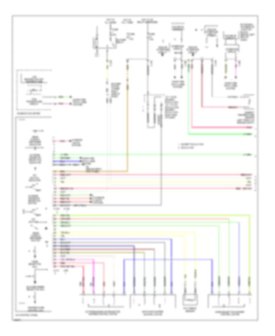
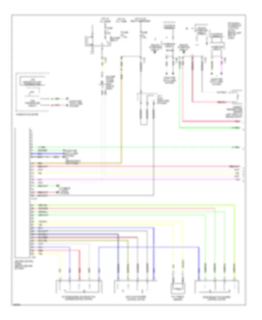
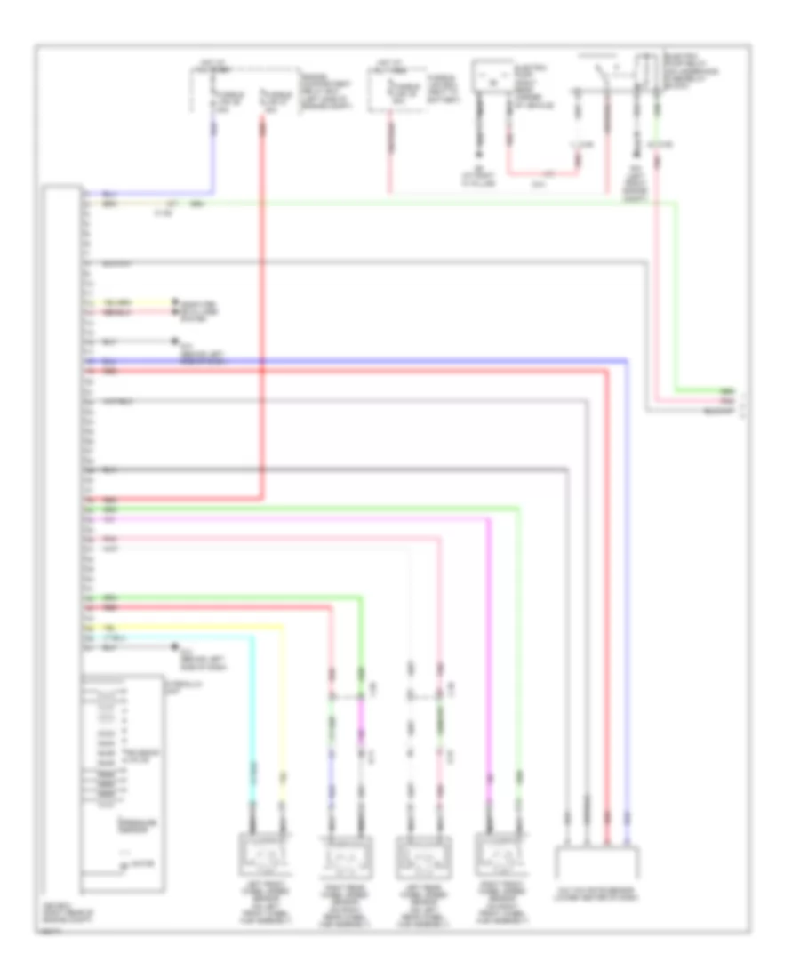
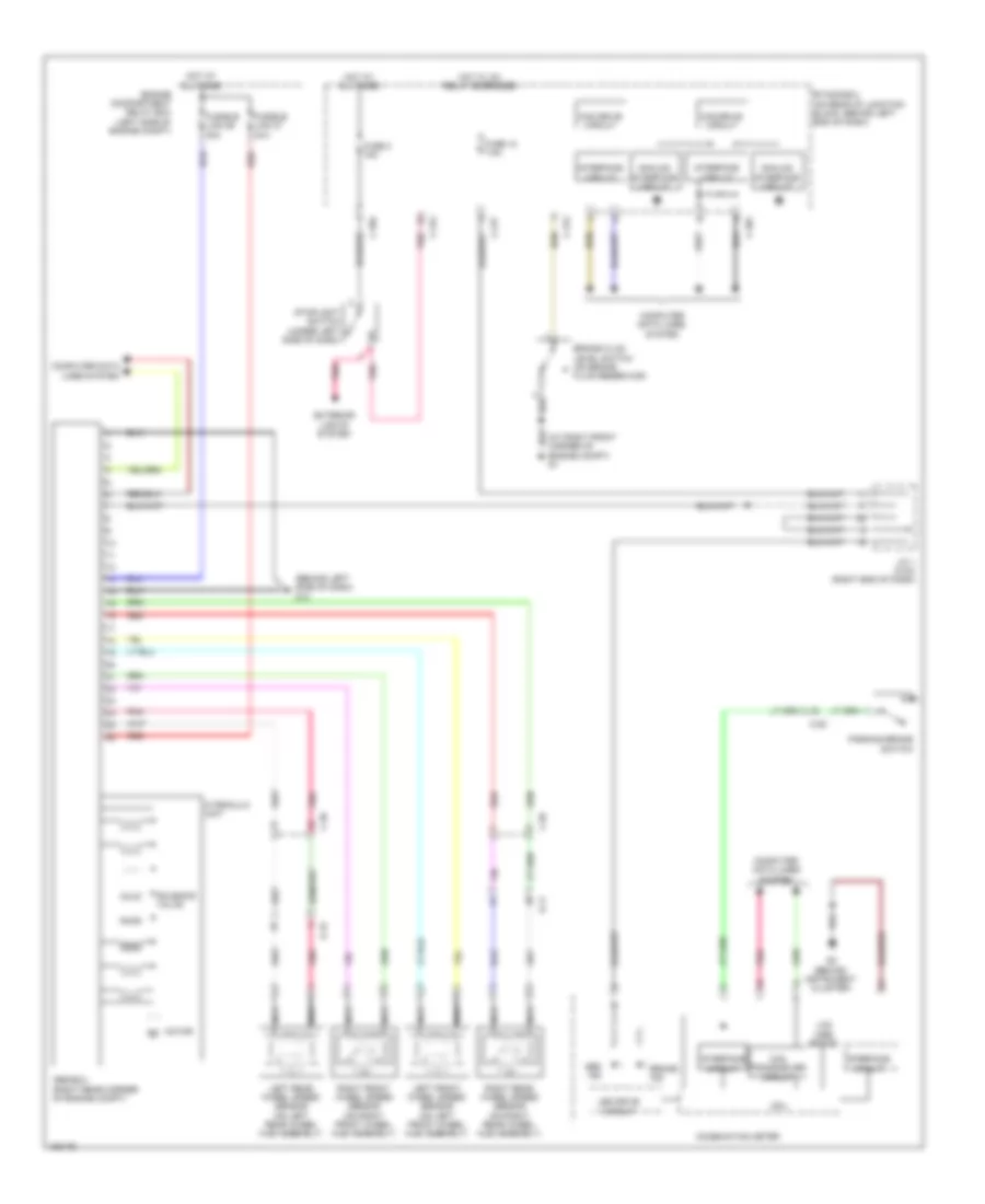
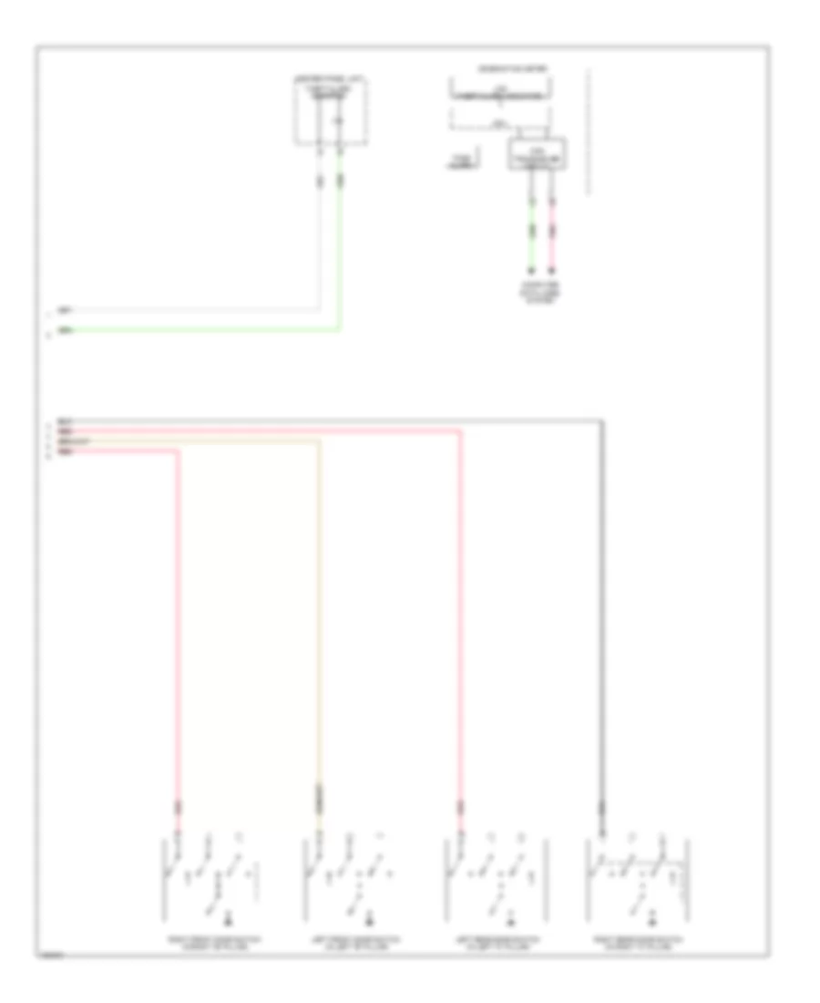
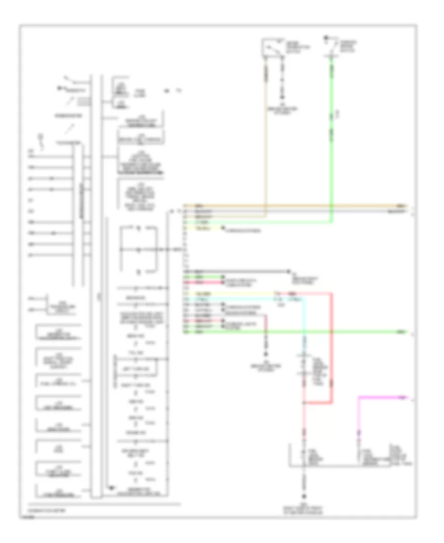
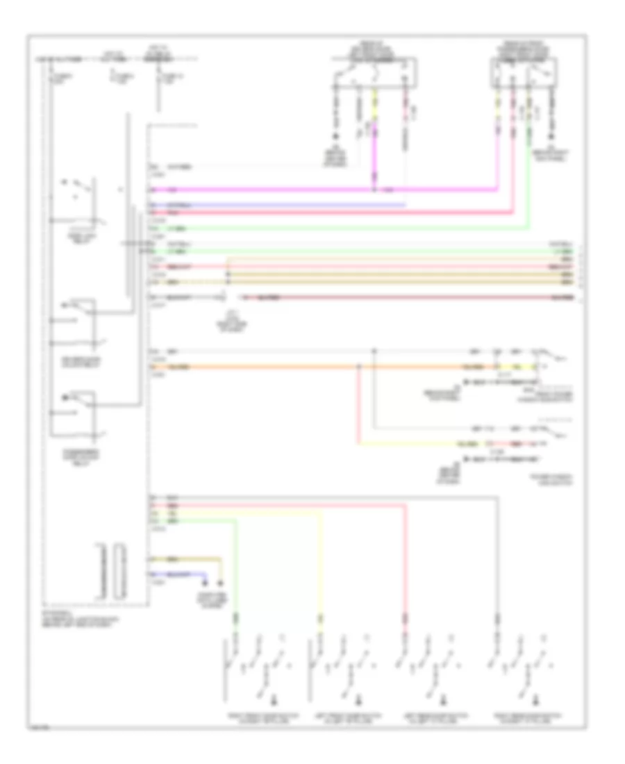
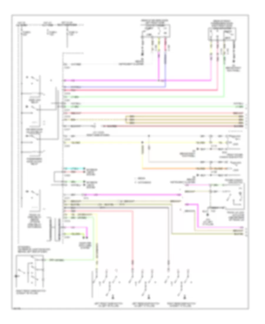
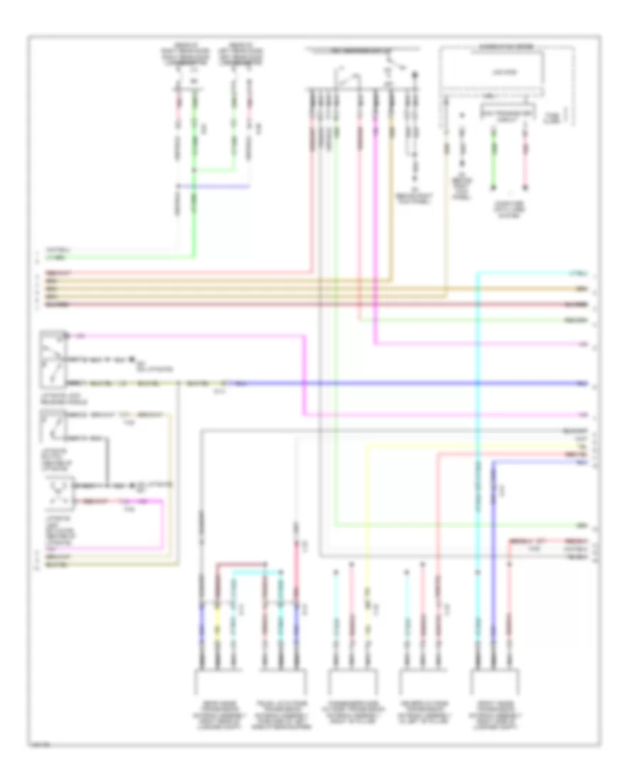
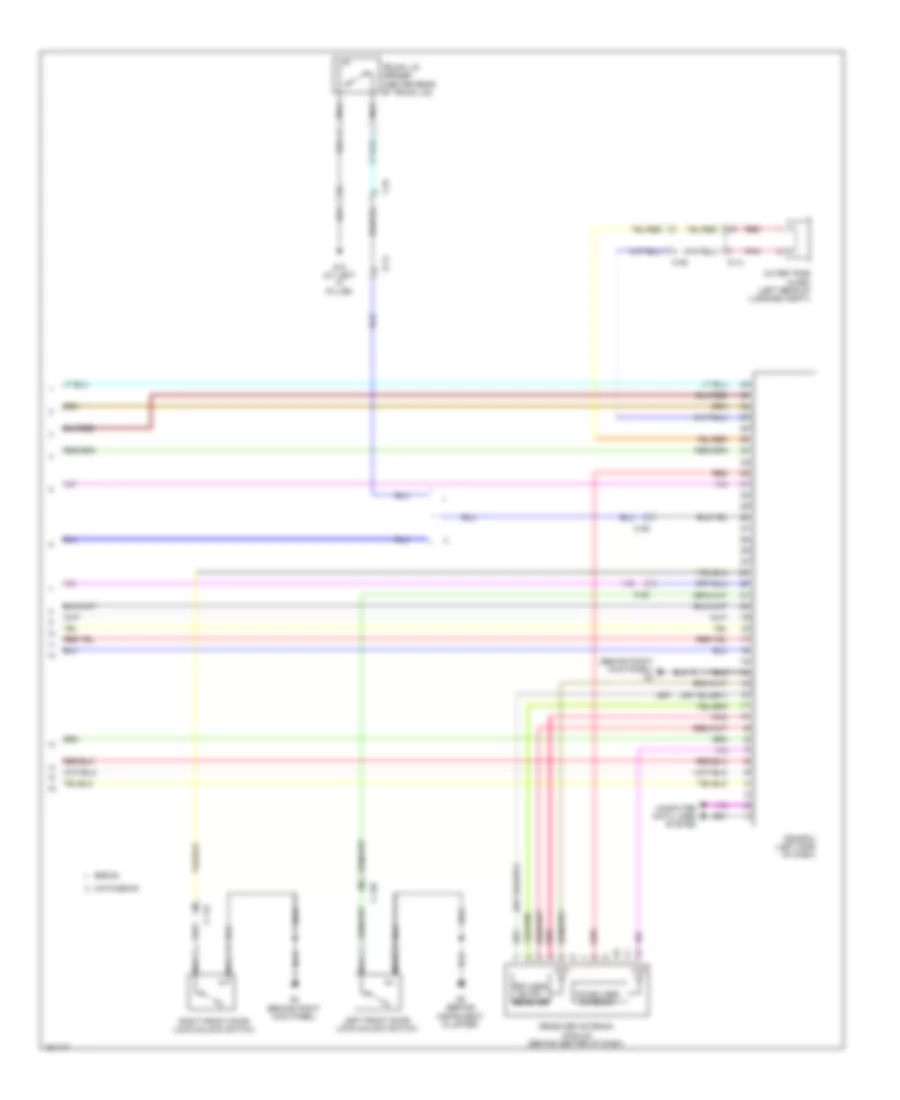
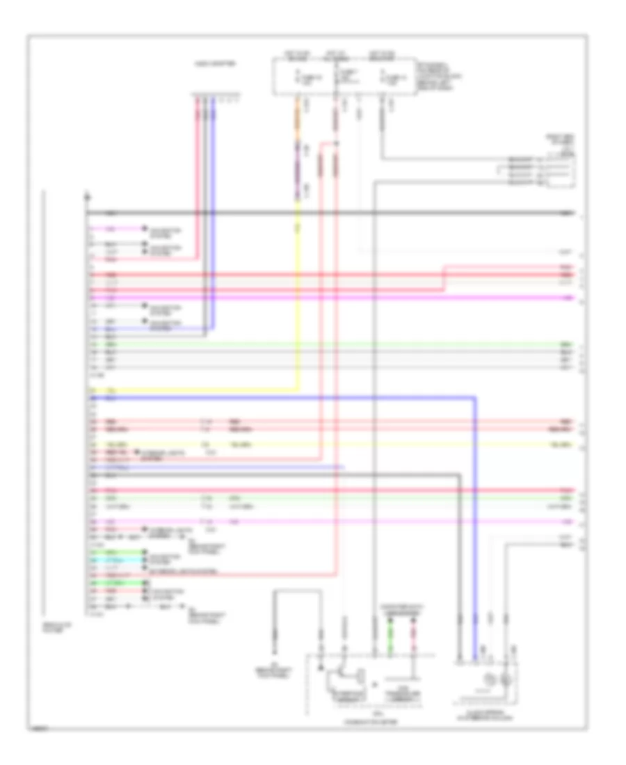
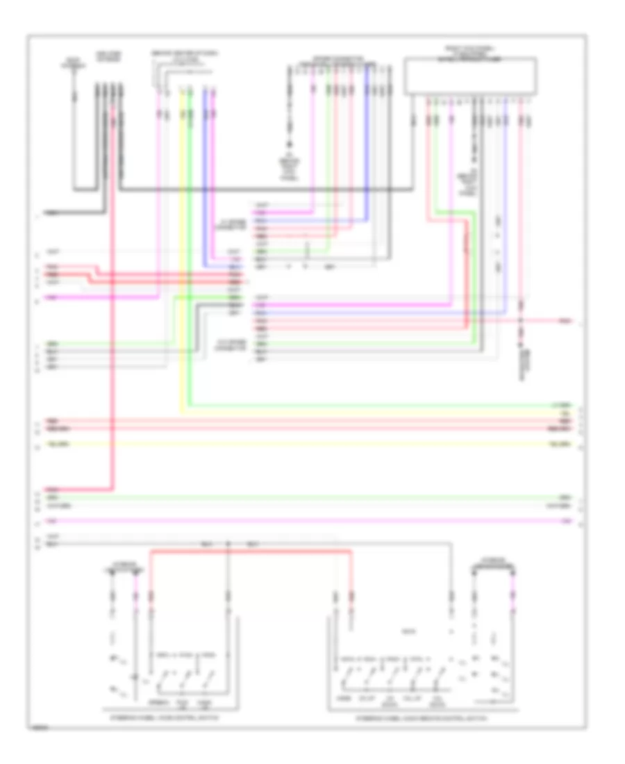
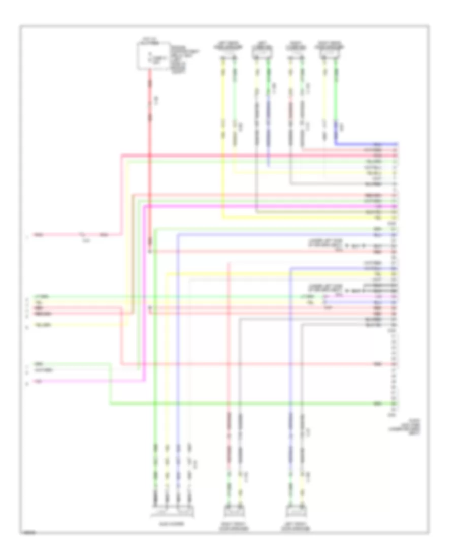
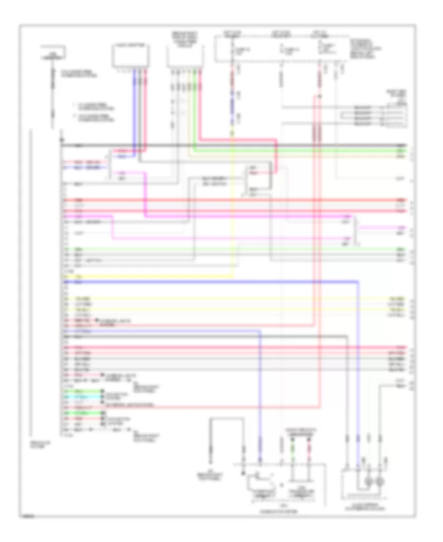
2.0L, Automatic A/C Wiring Diagram (1 of 2) for Mitsubishi Lancer ES 2014
 https://portal-diagnostov.com/license.html
Automotive Electricians Portal FZCO
Automotive Electricians Portal FZCO
https://portal-diagnostov.com/license.html
https://portal-diagnostov.com/license.html
Automotive Electricians Portal FZCO
Automotive Electricians Portal FZCO
List of elements for 2.0L, Automatic A/C Wiring Diagram (1 of 2) for Mitsubishi Lancer ES 2014:
- A/c control panel
- Air mixing damper control motor
- Ambient temperature sensor (left front of engine compt)
- Analog interface circuit
- Blower motor (under right side of dash)
- Blower relay
- C-146
- C-301
- C-312
- C-315
- C-317
- C-60
- Can drive circuit
- Can transceiver circuit
- Combination meter
- Computer data lines system
- Cpu
- Etacs-ecu (on rear of junction block, behind left end of dash)
- Fin thermo sensor
- Fuse 30a
- Fuse 7.5a
- G4 (behind right kick panel)
- Hot at all times
- Hot w/ ig1 relay energized
- Interface circuit
- Interior lights system
- J/c 1 (c-03) (right end of dash)
- Lcd (engine coolant temperature)
- Mode selection damper control motor
- Nca
- Outside/inside air selection damper control motor
- Pnk
- Red
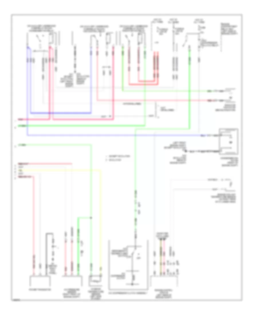
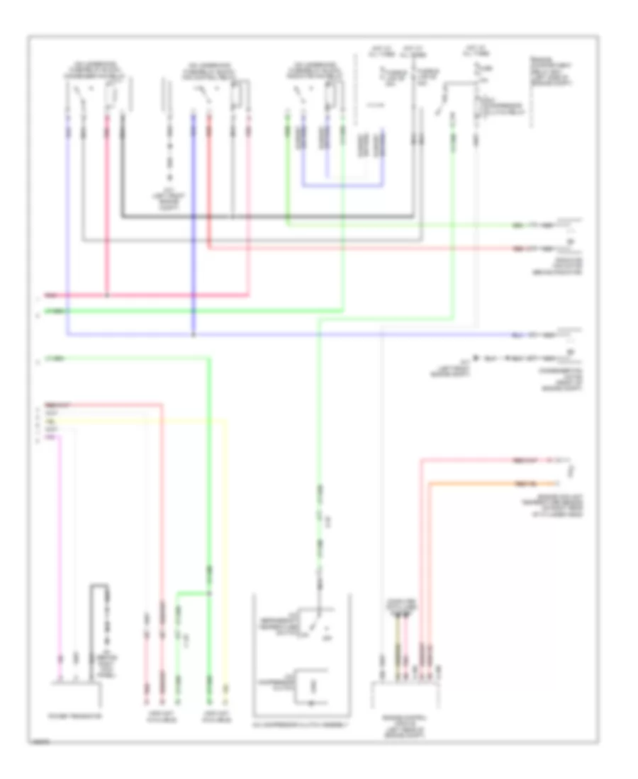
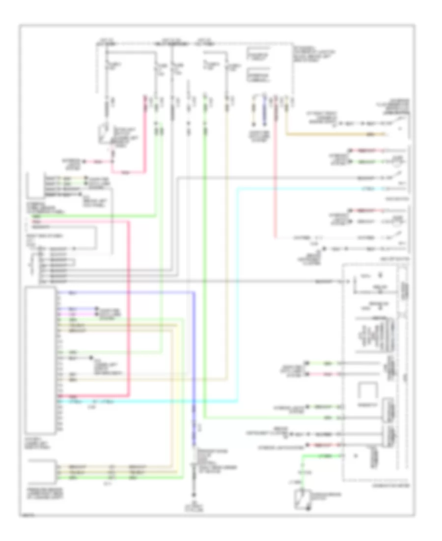
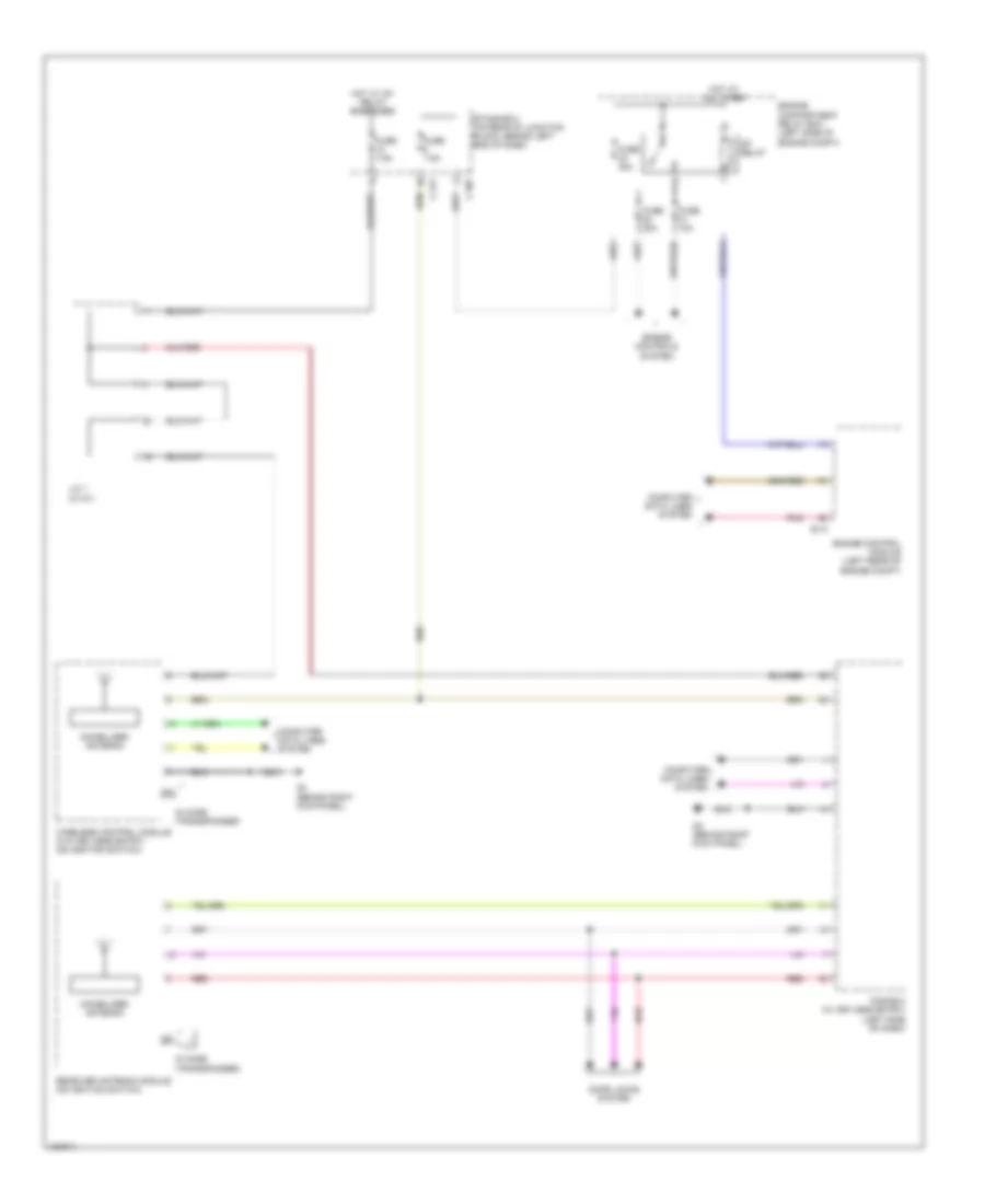
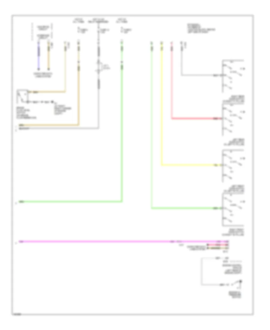
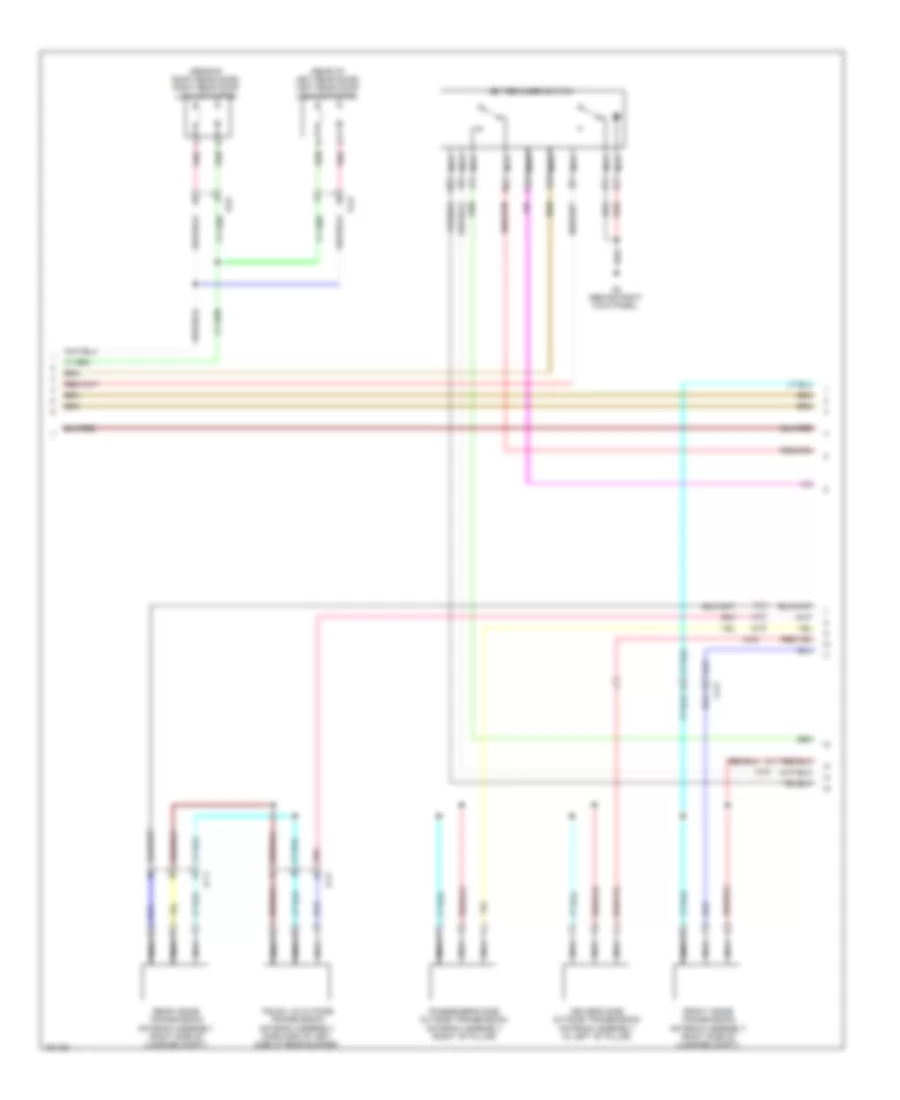
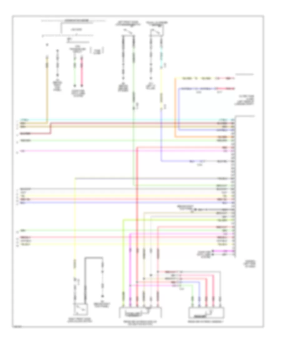
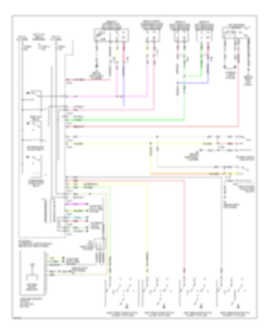
2.0L, Automatic A/C Wiring Diagram (2 of 2) for Mitsubishi Lancer ES 2014
List of elements for 2.0L, Automatic A/C Wiring Diagram (2 of 2) for Mitsubishi Lancer ES 2014:
- (on underhood fuse/relay block) condenser fan relay
- (on underhood fuse/relay block) fan control relay
- (on underhood fuse/relay block) radiator fan relay
- A-10
- A/c compressor clutch
- A/c compressor clutch assembly
- A/c compressor clutch relay
- A/c pressure sensor (right front of engine compt)
- A/c refrigerant temperature switch
- B-108
- B-109
- C-127
- Computer data lines system
- Condenser fan motor (front of engine compt)
- Engine compartment relay box (left side of engine compt)
- Engine control module (left rear of engine compt)
- Engine coolant temperature sensor (on right rear of cylinder head)
- Fuse 10a
- Fusible link 28 30a
- Fusible link 29 40a
- G17 (left front engine compt)
- G4 (behind right kick panel)
- Hot at all times
- Interior temperature sensor (left side of dash)
- Nca
- Off
- Pnk
- Power transistor
- Radiator fan motor (behind radiator)
- Red
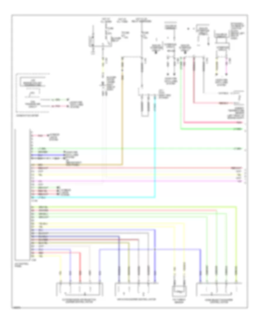
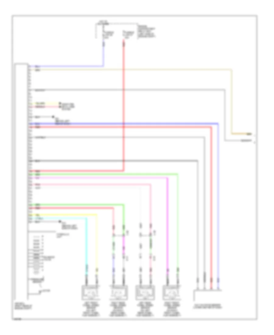
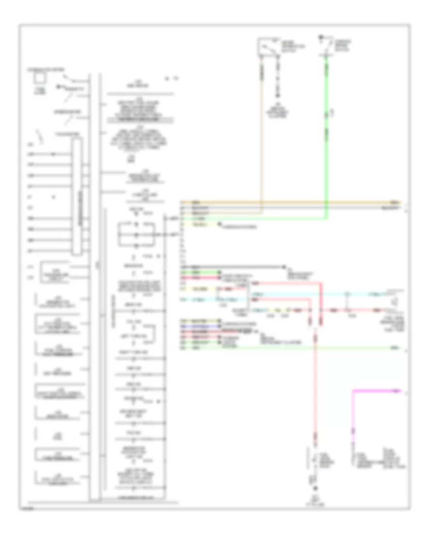
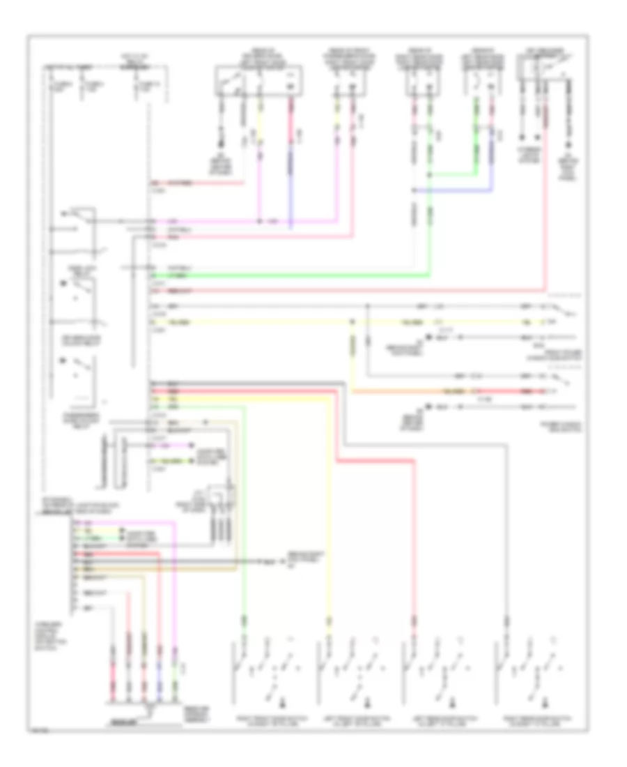
2.0L, Manual A/C Wiring Diagram (1 of 2) for Mitsubishi Lancer ES 2014
List of elements for 2.0L, Manual A/C Wiring Diagram (1 of 2) for Mitsubishi Lancer ES 2014:
- Air mixing damper control motor
- Ambient temperature sensor (left front of engine compt)
- Analog interface circuit
- Blower motor (under right side of dash)
- Blower relay
- C-147
- C-301
- C-312
- C-315
- C-317
- C-61
- Can drive circuit
- Can transceiver circuit
- Combination meter
- Computer data lines system
- Cpu
- Etacs-ecu (on rear of junction block, behind left end of dash)
- Fin thermo sensor
- Fuse 30a
- Fuse 7.5a
- G4 (behind right kick panel)
- Heater control panel (behind center of dash)
- Hot at all times
- Hot w/ ig1 relay energized
- Interface circuit
- Interior lights system
- J/c 1 (c-03) (right end of dash)
- Lcd (engine coolant temperature)
- Mode selection damper control motor
- Nca
- Outside/inside air selection damper control motor
- Pnk
- Red
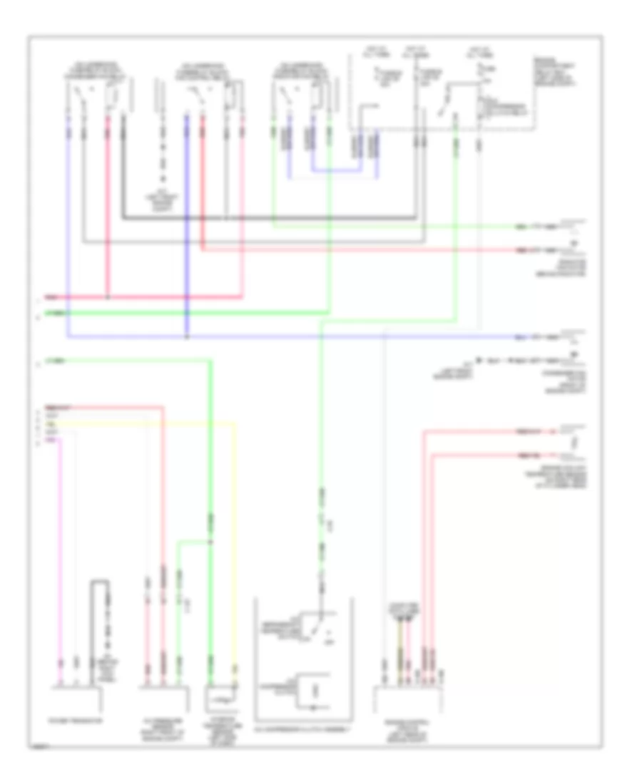
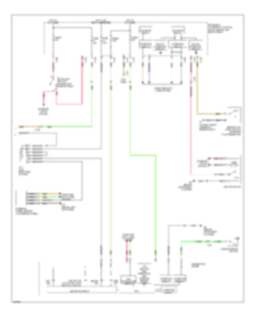
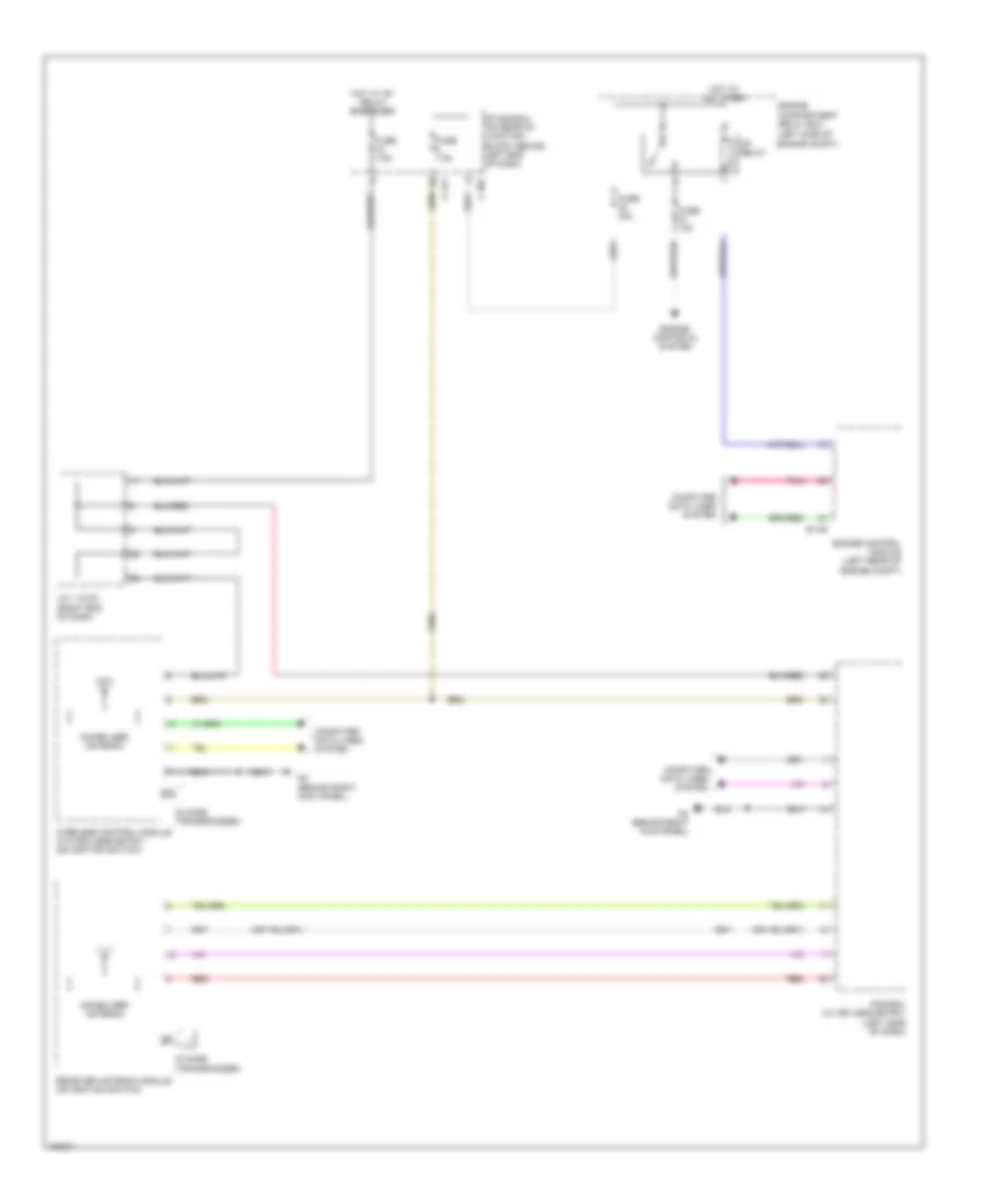
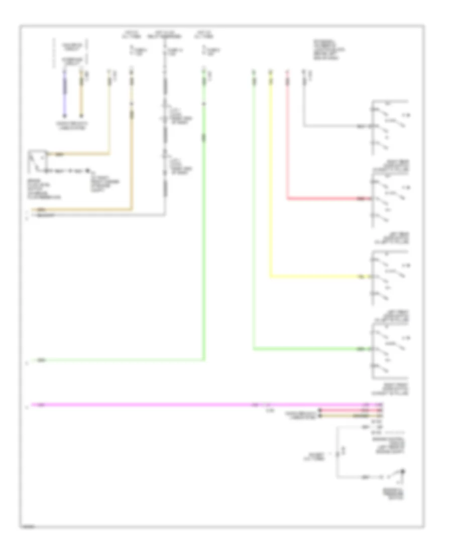
2.0L, Manual A/C Wiring Diagram (2 of 2) for Mitsubishi Lancer ES 2014
List of elements for 2.0L, Manual A/C Wiring Diagram (2 of 2) for Mitsubishi Lancer ES 2014:
- (info not available)
- (on underhood fuse/relay block) condenser fan relay
- (on underhood fuse/relay block) fan control relay
- (on underhood fuse/relay block) radiator fan relay
- A-10
- A/c compressor clutch
- A/c compressor clutch assembly
- A/c compressor clutch relay
- A/c refrigerant temperature switch
- B-108
- B-109
- C-127
- Computer data lines system
- Condenser fan motor (front of engine compt)
- Engine compartment relay box (left side of engine compt)
- Engine control module (left rear of engine compt)
- Engine coolant temperature sensor (on right rear of cylinder head)
- Fuse 10a
- Fusible link 28 30a
- Fusible link 29 40a
- G17 (left front engine compt)
- G4 (behind right kick panel)
- Hot at all times
- Nca
- Off
- Pnk
- Power transistor
- Radiator fan motor (behind radiator)
- Red
2.0L TURBO
2.0L Turbo, Automatic A/C Wiring Diagram (1 of 2) for Mitsubishi Lancer ES 2014
List of elements for 2.0L Turbo, Automatic A/C Wiring Diagram (1 of 2) for Mitsubishi Lancer ES 2014:
- A/c control panel
- A/c switch
- A/c switch indicator
- Air mixing damper control motor
- Ambient temperature sensor (left front of engine compt)
- Analog interface circuit
- Blower motor (under right side of dash)
- Blower relay
- Blower speed selection dial
- C-123
- C-141
- C-146
- C-301
- C-312
- C-315
- C-317
- C-60
- Can drive circuit
- Can transceiver circuit
- Combination meter
- Computer data lines system
- Cpu
- Etacs-ecu (on rear of junction block, behind left end of dash)
- Evolution
- Except evolution
- Fin thermo sensor
- Fuse 30a
- Fuse 7.5a
- G4 (behind right kick panel)
- Hot at all times
- Hot w/ ig1 relay energized
- Interface circuit
- Interior lights system
- J/c 1 (c-03) (except evolution) j/c 1 (c-101) (evolution) (except evolution: right end of dash)
- Lcd (engine coolant temperature)
- Mode selection damper control motor
- Mode selection dial
- Nca
- Off
- Outside/ inside air selection indicator
- Outside/ inside air selection switch
- Outside/inside air selection damper control motor
- Pnk
- Rear window defogger indicator
- Rear window defogger switch
- Red
- Temperature control dial
2.0L Turbo, Automatic A/C Wiring Diagram (2 of 2) for Mitsubishi Lancer ES 2014
List of elements for 2.0L Turbo, Automatic A/C Wiring Diagram (2 of 2) for Mitsubishi Lancer ES 2014:
- (left front engine compt) (except evolution) g17
- (on auxiliary underhood fuse/relay block) condenser fan relay
- (on auxiliary underhood fuse/relay block) fan control relay
- (on auxiliary underhood fuse/relay block) radiator fan relay
- A-13
- A-54
- A/c compressor clutch
- A/c compressor clutch assembly
- A/c compressor clutch relay
- A/c pressure sensor (right front of engine compt)
- A/c refrigerant temperature switch
- B-09
- B-10
- B-108
- B-109
- C-127
- C-130
- Computer data lines system
- Condenser fan motor (front of engine compt)
- Engine compartment relay box (left side of engine compt)
- Engine control module (left rear of engine compt)
- Engine coolant temperature sensor (on right rear of cylinder head)
- Evolution
- Except evolution
- Fuse 10a
- Fusible link 28 30a
- Fusible link 29 40a
- G16 (evolution) (rear of engine compt)
- G17 (except evolution) (left front engine compt)
- G4 (behind right kick panel)
- Hot at all times
- Interior temperature sensor (left side of dash)
- Nca
- Off
- Pnk
- Power transistor
- Radiator fan motor (behind radiator)
- Red
2.4L
2.4L, Automatic A/C Wiring Diagram (1 of 2) for Mitsubishi Lancer ES 2014
List of elements for 2.4L, Automatic A/C Wiring Diagram (1 of 2) for Mitsubishi Lancer ES 2014:
- A/c control panel
- Air mixing damper control motor
- Ambient temperature sensor (left front of engine compt)
- Analog interface circuit
- Blower motor (under right side of dash)
- Blower relay
- C-146
- C-301
- C-312
- C-315
- C-317
- C-60
- Can drive circuit
- Can transceiver circuit
- Combination meter
- Computer data lines system
- Cpu
- Etacs-ecu (on rear of junction block, behind left end of dash)
- Fin thermo sensor
- Fuse 30a
- Fuse 7.5a
- G4 (behind right kick panel)
- Hot at all times
- Hot w/ ig1 relay energized
- Interface circuit
- Interior lights system
- J/c 1 (c-03) (right end of dash)
- Lcd (engine coolant temperature)
- Mode selection damper control motor
- Nca
- Outside/inside air selection damper control motor
- Pnk
- Red
2.4L, Automatic A/C Wiring Diagram (2 of 2) for Mitsubishi Lancer ES 2014
List of elements for 2.4L, Automatic A/C Wiring Diagram (2 of 2) for Mitsubishi Lancer ES 2014:
- (on underhood fuse/relay block) condenser fan relay
- (on underhood fuse/relay block) fan control relay
- (on underhood fuse/relay block) radiator fan relay
- A-10
- A/c compressor clutch
- A/c compressor clutch assembly
- A/c compressor clutch relay
- A/c pressure sensor (right front of engine compt)
- A/c refrigerant temperature switch
- B-108
- B-109
- C-127
- Computer data lines system
- Condenser fan motor (front of engine compt)
- Engine compartment relay box (left side of engine compt)
- Engine control module (left rear of engine compt)
- Engine coolant temperature sensor (on right rear of cylinder head)
- Fuse 10a
- Fusible link 28 30a
- Fusible link 29 40a
- G17 (left front engine compt)
- G4 (behind right kick panel)
- Hot at all times
- Interior temperature sensor (left side of dash)
- Nca
- Off
- Pnk
- Power transistor
- Radiator fan motor (behind radiator)
- Red
2.4L, Manual A/C Wiring Diagram (1 of 2) for Mitsubishi Lancer ES 2014
List of elements for 2.4L, Manual A/C Wiring Diagram (1 of 2) for Mitsubishi Lancer ES 2014:
- Air mixing damper control motor
- Ambient temperature sensor (left front of engine compt)
- Analog interface circuit
- Blower motor (under right side of dash)
- Blower relay
- C-147
- C-301
- C-312
- C-315
- C-317
- C-61
- Can drive circuit
- Can transceiver circuit
- Combination meter
- Computer data lines system
- Cpu
- Etacs-ecu (on rear of junction block, behind left end of dash)
- Fin thermo sensor
- Fuse 30a
- Fuse 7.5a
- G4 (behind right kick panel)
- Heater control panel (behind center of dash)
- Hot at all times
- Hot w/ ig1 relay energized
- Interface circuit
- Interior lights system
- J/c 1 (c-03) (right end of dash)
- Lcd (engine coolant temperature)
- Mode selection damper control motor
- Nca
- Outside/inside air selection damper control motor
- Pnk
- Red
2.4L, Manual A/C Wiring Diagram (2 of 2) for Mitsubishi Lancer ES 2014
List of elements for 2.4L, Manual A/C Wiring Diagram (2 of 2) for Mitsubishi Lancer ES 2014:
- (info not available)
- (on underhood fuse/relay block) condenser fan relay
- (on underhood fuse/relay block) fan control relay
- (on underhood fuse/relay block) radiator fan relay
- A-10
- A/c compressor clutch
- A/c compressor clutch assembly
- A/c compressor clutch relay
- A/c refrigerant temperature switch
- B-108
- B-109
- C-127
- Computer data lines system
- Condenser fan motor (front of engine compt)
- Engine compartment relay box (left side of engine compt)
- Engine control module (left rear of engine compt)
- Engine coolant temperature sensor (on right rear of cylinder head)
- Fuse 10a
- Fusible link 28 30a
- Fusible link 29 40a
- G17 (left front engine compt)
- G4 (behind right kick panel)
- Hot at all times
- Nca
- Off
- Pnk
- Power transistor
- Radiator fan motor (behind radiator)
- Red
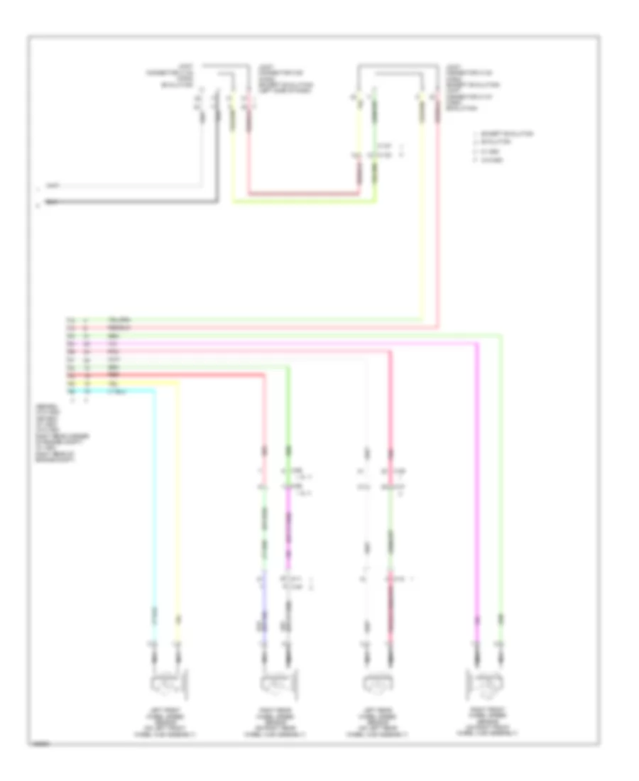
ANTI-LOCK BRAKES
2.0L
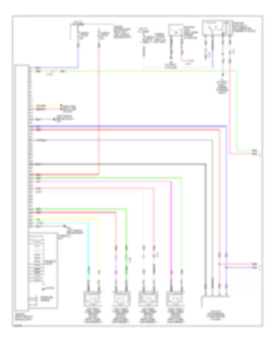
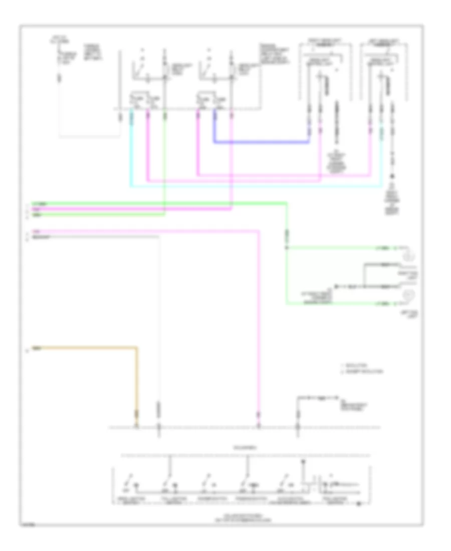
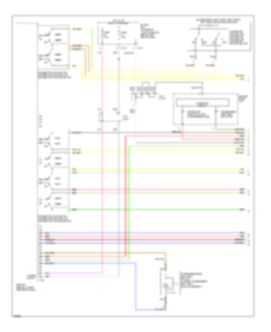
2.0L, Anti-lock Brakes Wiring Diagram, with Active Skid Control (1 of 2) for Mitsubishi Lancer ES 2014
List of elements for 2.0L, Anti-lock Brakes Wiring Diagram, with Active Skid Control (1 of 2) for Mitsubishi Lancer ES 2014:
- Asc-ecu (right rear of engine compt)
- C-39
- C-56
- Computer data lines system
- D-11
- D-15
- Engine compartment relay box (left side of engine compt)
- Fusible link 26 40a
- Fusible link 27 30a
- G & yaw rate sensor (lower center of dash)
- G13 (behind left side of dash)
- Hot at all times
- Hydraulic unit
- Left front wheel speed sensor (on left front wheel hub assembly)
- Left rear wheel speed sensor (on left rear wheel hub assembly)
- Motor m
- Nca
- Pnk
- Pressure sensor
- Red
- Right front wheel speed sensor (on right front wheel hub assembly)
- Right rear wheel speed sensor (on right rear wheel hub assembly)
- Solenoid valve
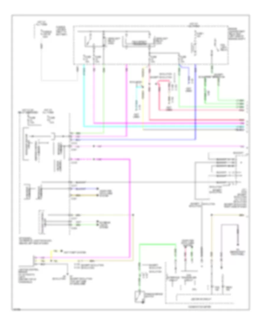
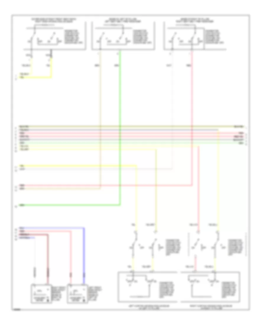
2.0L, Anti-lock Brakes Wiring Diagram, with Active Skid Control (2 of 2) for Mitsubishi Lancer ES 2014
List of elements for 2.0L, Anti-lock Brakes Wiring Diagram, with Active Skid Control (2 of 2) for Mitsubishi Lancer ES 2014:
- (at right front corner of engine compt)
- (not used)
- Abs ind
- Analog interface circuit
- Asc ind
- Asc off ind (w/o color liquid crystal display)
- Asc off switch
- Brake fluid level switch (on brake fluid reservoir)
- Brake ind
- C-128
- C-22
- C-301
- C-304
- C-311
- C-312
- C-313
- C-315
- C-317
- C-35
- C-51
- Can drive circuit
- Can transceiver circuit
- Combination meter
- Computer data lines system
- Cpu
- Etacs-ecu (on rear of junction block, behind left end of dash)
- Exterior lights system
- Fuse 10a
- Fuse 2 15a
- Fuse 7.5a
- Fuse 8 7.5a
- Fuse 9 15a
- G14 (behind left kick panel)
- G5 (behind instrument cluster)
- Hot at all times
- Hot w/ ig1 relay energized
- Illum
- Interface circuit
- Interior lights system
- J/c 1 (c-03) (right end of dash)
- Lcd (asc off) (asc operation) (asc warning) (brake) (abs)
- Led drive circuit
- Nca
- Parking brake switch
- Pnk
- Steering wheel sensor (in steering wheel)
- Stoplight switch (under left side of dash)
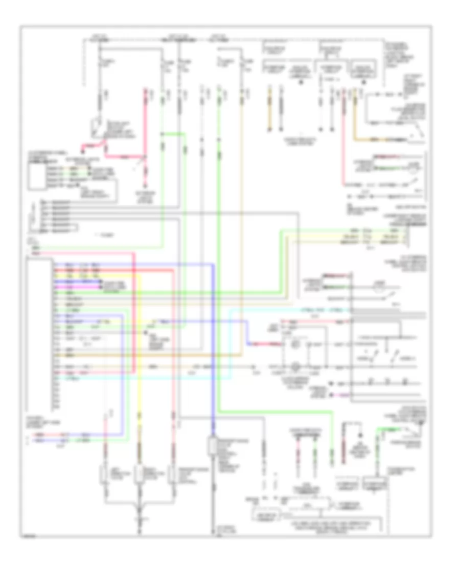
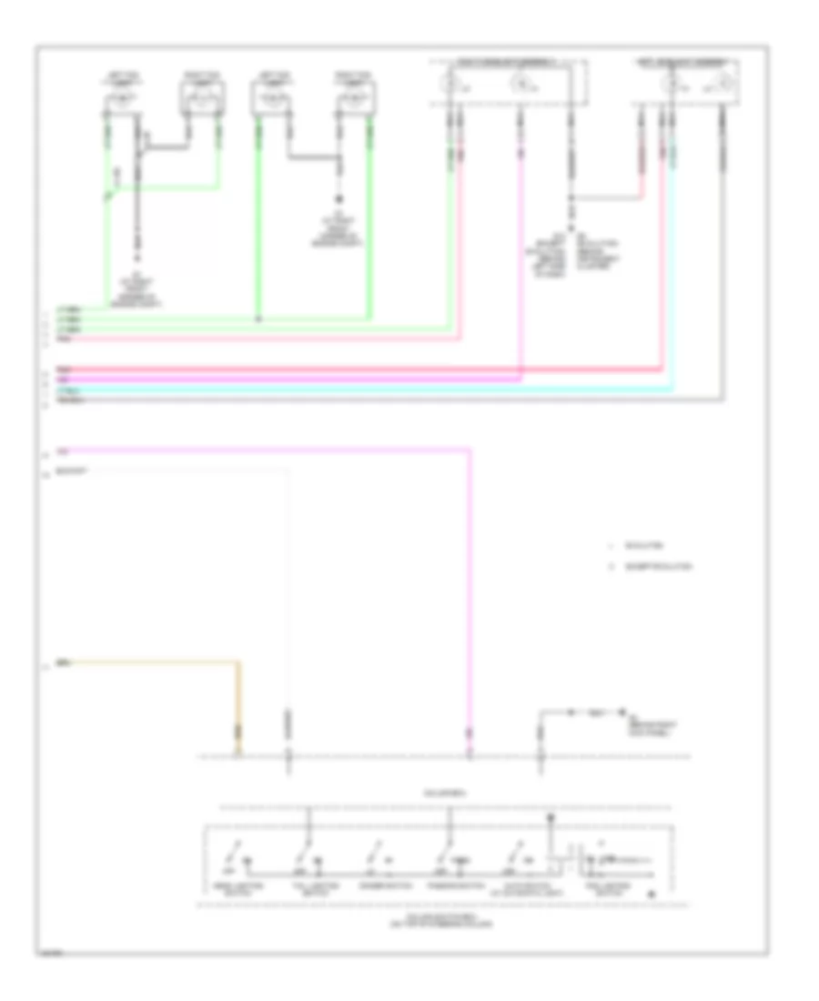
2.0L, Anti-lock Brakes Wiring Diagram, without Active Skid Control for Mitsubishi Lancer ES 2014
List of elements for 2.0L, Anti-lock Brakes Wiring Diagram, without Active Skid Control for Mitsubishi Lancer ES 2014:
- (at right front corner of engine compt) g1
- (behind left side of dash) g13
- Abs ind
- Abs-ecu (right rear corner of engine compt)
- Analog interface circuit
- Brake fluid level switch (on brake fluid reservoir)
- Brake ind
- C-22
- C-301
- C-304
- C-312
- C-317
- C-39
- C-56
- Can drive circuit
- Can transceiver circuit
- Combination meter
- Computer data lines system
- Cpu
- D-11
- D-15
- Engine compartment relay box (left side of engine compt)
- Etacs-ecu (on rear of junction block, behind left end of dash)
- Exterior lights system
- Fuse 12 7.5a
- Fuse 2 15a
- Fusible link 26 40a
- Fusible link 27 30a
- G5 (behind instrument cluster)
- Hot at all times
- Hot w/ ig1 relay energized
- Hydraulic unit
- Interface circuit
- J/c 1 (c-03) (right end of dash)
- Lcd (abs brake)
- Led drive circuit
- Left front wheel speed sensor (on left front wheel hub assembly)
- Left rear wheel speed sensor (on left rear wheel hub assembly)
- Motor
- Nca
- Parking brake switch
- Pnk
- Red
- Right front wheel speed sensor (on right front wheel hub assembly)
- Right rear wheel speed sensor (on right rear wheel hub assembly)
- Solenoid valve
- Stoplight switch (under left side of dash)
2.0L TURBO
2.0L Turbo, Anti-lock Brakes Wiring Diagram, Evolution (1 of 2) for Mitsubishi Lancer ES 2014
List of elements for 2.0L Turbo, Anti-lock Brakes Wiring Diagram, Evolution (1 of 2) for Mitsubishi Lancer ES 2014:
- (left side of engine compt) g19
- Asc-ecu (right rear of engine compt)
- C-131
- C-21
- C-45
- C-47
- Computer data lines system
- D-12
- Electric pump (right rear corner of vehicle)
- Electric pump relay (on underhood fuse/relay block)
- Engine compartment relay box (left side of engine compt)
- Fusible link 26 40a
- Fusible link 27 30a
- Fusible link 35 80a
- Fusible link box (next to battery)
- G & yaw rate sensor (lower center of dash)
- G1 (at right front corner of engine compt)
- G19 (left side of engine compt)
- G9 (at right "c" pillar)
- Hot at all times
- Hydraulic unit
- Left front wheel speed sensor (on left front wheel hub assembly)
- Left rear wheel speed sensor (on left rear wheel hub assembly)
- Motor m
- Nca
- Pnk
- Pressure sensor
- Red
- Right front wheel speed sensor (on right front wheel hub assembly)
- Right rear wheel speed sensor (on right rear wheel hub assembly)
- Solenoid valve
2.0L Turbo, Anti-lock Brakes Wiring Diagram, Evolution (2 of 2) for Mitsubishi Lancer ES 2014
List of elements for 2.0L Turbo, Anti-lock Brakes Wiring Diagram, Evolution (2 of 2) for Mitsubishi Lancer ES 2014:
- (at right "c" pillar) g9
- (at right front corner of engine compt) g1
- (in steering wheel) steering wheel sensor
- (not used) c-206
- (on brake fluid reservoir) brake fluid level switch
- (under right rear of luggage compt) pressure sensor
- (w/ steering wheel audio remote control switch) awc switch
- Abs ind
- Analog interface circuit
- Asc off switch
- Awc switch (w/o steering wheel audio remote control switch)
- Awc-ecu (under left side of dash)
- Brake ind
- C-202
- C-205
- C-23
- C-301
- C-304
- C-31
- C-311
- C-312
- C-313
- C-315
- C-317
- C-41
- C-47
- Can drive circuit
- Can transceiver circuit
- Clock spring (in steering column)
- Combination meter
- Computer data lines system
- Cpu
- D-11
- Etacs-ecu (on rear of junction block, behind left end of dash)
- Exterior lights system
- F-11
- Fuse 10a
- Fuse 2 15a
- Fuse 7.5a
- Fuse 9 15a
- G18 (left front engine compt)
- G20 (left side engine compt)
- G6 (behind center of dash)
- Hot at all times
- Hot w/ ig1 relay energized
- Ill
- Illum
- Interface circuit
- Interior lights system
- J/c 1 (c-101)
- Lcd (abs) (acd) (asc off) (asc operation) (asc warning) (brake) (gravel) (ayc) (snow) (tarmac)
- Led drive circuit
- Left direction valve
- Mode (+)
- Mode (-)
- Nca
- Parking brake switch
- Pnk
- Proportioning valve (acd control) (right rear corner of vehicle)
- Proportioning valve (ayc control)
- Red
- Right direction valve
- Stoplight switch (under left side of dash)
- Tc-sst
2.0L Turbo, Anti-lock Brakes Wiring Diagram, Except Evolution with Active Skid Control (1 of 2) for Mitsubishi Lancer ES 2014
List of elements for 2.0L Turbo, Anti-lock Brakes Wiring Diagram, Except Evolution with Active Skid Control (1 of 2) for Mitsubishi Lancer ES 2014:
- Asc-ecu (right rear of engine compt)
- C-128
- C-39
- C-46
- C-56
- Computer data lines system
- D-11
- D-15
- D-41
- Electric pump (right rear corner of vehicle)
- Electric pump relay (on underhood fuse/relay block)
- Engine compartment relay box (left side of engine compt)
- Fusible link 26 40a
- Fusible link 27 30a
- Fusible link 35 80a
- Fusible link box (next to battery)
- G & yaw rate sensor (lower center of dash)
- G13 (behind left side of dash)
- G18 (left front engine compt)
- G9 (at right "c" pillar)
- Hot at all times
- Hydraulic unit
- Left front wheel speed sensor (on left front wheel hub assembly)
- Left rear wheel speed sensor (on left rear wheel hub assembly)
- Motor m
- Nca
- Pnk
- Pressure sensor
- Red
- Right front wheel speed sensor (on right front wheel hub assembly)
- Right rear wheel speed sensor (on right rear wheel hub assembly)
- Solenoid valve
2.0L Turbo, Anti-lock Brakes Wiring Diagram, Except Evolution with Active Skid Control (2 of 2) for Mitsubishi Lancer ES 2014
List of elements for 2.0L Turbo, Anti-lock Brakes Wiring Diagram, Except Evolution with Active Skid Control (2 of 2) for Mitsubishi Lancer ES 2014:
- (abs)
- (acd)
- (asc off) (asc operation)
- (asc warning)
- (at right front corner of engine compt) g1
- (behind instrument cluster) g5
- (brake)
- (c-03)
- (gravel)
- (on brake fluid reservoir) brake fluid level switch
- (right end of dash) j/c 1
- (snow)
- (tarmac)
- Abs ind
- Asc ind
- Asc off switch
- Awc switch
- Awc-ecu (under left side of dash)
- Brake ind
- C-22
- C-301
- C-304
- C-311
- C-312
- C-313
- C-315
- C-317
- C-35
- Can drive circuit
- Circuit interface
- Circuit transceiver can
- Combination meter
- Computer data lines system
- Cpu
- D-11
- Etacs-ecu (on rear of junction block, behind left end of dash)
- Exterior lights system
- Fuse 10a
- Fuse 2 15a
- Fuse 7.5a
- Fuse 8 7.5a
- Fuse 9 15a
- G12 (under left side of driver's seat)
- G14 (behind left kick panel)
- G5 (behind instrument cluster)
- G9 (at right "c" pillar)
- Hot at all times
- Hot w/ ig1 relay energized
- Illum
- Interface circuit
- Interior lights system
- Lcd
- Led drive circuit
- Nca
- Parking brake switch
- Pnk
- Pressure sensor (under right rear of luggage compt)
- Proportioning valve (acd control) (right rear corner of vehicle)
- Rheostat
- Steering wheel sensor (in steering wheel)
- Stoplight switch (under left side of dash)
2.0L Turbo, Anti-lock Brakes Wiring Diagram, Except Evolution without Active Skid Control for Mitsubishi Lancer ES 2014
List of elements for 2.0L Turbo, Anti-lock Brakes Wiring Diagram, Except Evolution without Active Skid Control for Mitsubishi Lancer ES 2014:
- (at right front corner of engine compt) g1
- (behind left side of dash) g13
- Abs ind
- Abs-ecu (right rear corner of engine compt)
- Analog interface circuit
- Brake fluid level switch (on brake fluid reservoir)
- Brake ind
- C-22
- C-301
- C-304
- C-312
- C-317
- C-39
- C-56
- Can drive circuit
- Can transceiver circuit
- Combination meter
- Computer data lines system
- Cpu
- D-11
- D-15
- Engine compartment relay box (left side of engine compt)
- Etacs-ecu (on rear of junction block, behind left end of dash)
- Exterior lights system
- Fuse 12 7.5a
- Fuse 2 15a
- Fusible link 26 40a
- Fusible link 27 30a
- G5 (behind instrument cluster)
- Hot at all times
- Hot w/ ig1 relay energized
- Hydraulic unit
- Interface circuit
- J/c 1 (c-03) (right end of dash)
- Lcd (abs brake)
- Led drive circuit
- Left front wheel speed sensor (on left front wheel hub assembly)
- Left rear wheel speed sensor (on left rear wheel hub assembly)
- Motor
- Nca
- Parking brake switch
- Pnk
- Red
- Right front wheel speed sensor (on right front wheel hub assembly)
- Right rear wheel speed sensor (on right rear wheel hub assembly)
- Solenoid valve
- Stoplight switch (under left side of dash)
2.4L
2.4L, Anti-lock Brakes Wiring Diagram, with Active Skid Control (1 of 2) for Mitsubishi Lancer ES 2014
List of elements for 2.4L, Anti-lock Brakes Wiring Diagram, with Active Skid Control (1 of 2) for Mitsubishi Lancer ES 2014:
- Asc-ecu (right rear of engine compt)
- C-39
- C-56
- Computer data lines system
- D-11
- D-15
- Engine compartment relay box (left side of engine compt)
- Fusible link 26 40a
- Fusible link 27 30a
- G & yaw rate sensor (lower center of dash)
- G13 (behind left side of dash)
- Hot at all times
- Hydraulic unit
- Left front wheel speed sensor (on left front wheel hub assembly)
- Left rear wheel speed sensor (on left rear wheel hub assembly)
- Motor m
- Nca
- Pnk
- Pressure sensor
- Red
- Right front wheel speed sensor (on right front wheel hub assembly)
- Right rear wheel speed sensor (on right rear wheel hub assembly)
- Solenoid valve
2.4L, Anti-lock Brakes Wiring Diagram, with Active Skid Control (2 of 2) for Mitsubishi Lancer ES 2014
List of elements for 2.4L, Anti-lock Brakes Wiring Diagram, with Active Skid Control (2 of 2) for Mitsubishi Lancer ES 2014:
- (at right front corner of engine compt)
- (not used)
- Abs ind
- Analog interface circuit
- Asc ind
- Asc off ind (w/o color liquid crystal display)
- Asc off switch
- Brake fluid level switch (on brake fluid reservoir)
- Brake ind
- C-128
- C-22
- C-301
- C-304
- C-311
- C-312
- C-313
- C-315
- C-317
- C-35
- C-51
- Can drive circuit
- Can transceiver circuit
- Combination meter
- Computer data lines system
- Cpu
- Etacs-ecu (on rear of junction block, behind left end of dash)
- Exterior lights system
- Fuse 10a
- Fuse 2 15a
- Fuse 7.5a
- Fuse 8 7.5a
- Fuse 9 15a
- G14 (behind left kick panel)
- G5 (behind instrument cluster)
- Hot at all times
- Hot w/ ig1 relay energized
- Illum
- Interface circuit
- Interior lights system
- J/c 1 (c-03) (right end of dash)
- Lcd (asc off) (asc operation) (asc warning) (brake) (abs)
- Led drive circuit
- Nca
- Parking brake switch
- Pnk
- Steering wheel sensor (in steering wheel)
- Stoplight switch (under left side of dash)
2.4L, Anti-lock Brakes Wiring Diagram, without Active Skid Control for Mitsubishi Lancer ES 2014
List of elements for 2.4L, Anti-lock Brakes Wiring Diagram, without Active Skid Control for Mitsubishi Lancer ES 2014:
- (at right front corner of engine compt) g1
- (behind left side of dash) g13
- Abs ind
- Abs-ecu (right rear corner of engine compt)
- Analog interface circuit
- Brake fluid level switch (on brake fluid reservoir)
- Brake ind
- C-22
- C-301
- C-304
- C-312
- C-317
- C-39
- C-56
- Can drive circuit
- Can transceiver circuit
- Combination meter
- Computer data lines system
- Cpu
- D-11
- D-15
- Engine compartment relay box (left side of engine compt)
- Etacs-ecu (on rear of junction block, behind left end of dash)
- Exterior lights system
- Fuse 12 7.5a
- Fuse 2 15a
- Fusible link 26 40a
- Fusible link 27 30a
- G5 (behind instrument cluster)
- Hot at all times
- Hot w/ ig1 relay energized
- Hydraulic unit
- Interface circuit
- J/c 1 (c-03) (right end of dash)
- Lcd (abs brake)
- Led drive circuit
- Left front wheel speed sensor (on left front wheel hub assembly)
- Left rear wheel speed sensor (on left rear wheel hub assembly)
- Motor
- Nca
- Parking brake switch
- Pnk
- Red
- Right front wheel speed sensor (on right front wheel hub assembly)
- Right rear wheel speed sensor (on right rear wheel hub assembly)
- Solenoid valve
- Stoplight switch (under left side of dash)
ANTI-THEFT
Forced Entry Wiring Diagram, Evolution (1 of 2) for Mitsubishi Lancer ES 2014
List of elements for Forced Entry Wiring Diagram, Evolution (1 of 2) for Mitsubishi Lancer ES 2014:
- (behind center of dash) g6
- C-301
- C-312
- C-313
- C-317
- C-41
- Can drive circuit
- Center panel unit
- Circuit can drive
- Circuit interface
- Computer data lines system
- D-16
- Door locks system
- Etacs-ecu (on rear of junction block, behind left end of dash)
- F-27
- Fuse 15a
- Fuse 7.5a
- G11 (left "c" pillar)
- G4 (behind right kick panel)
- Hot at all times
- Hot w/ ig1 relay energized
- Immobilizer antenna
- J/c 1 (c-101)
- J/c can 1 (c-105)
- Kos-ecu (w/ keyless entry) (left side of dash)
- Pnk
- Receiver
- Receiver antenna assembly
- Red
- Theft-alarm indicator
- Trunk lid latch
- W/ keyless entry
- W/o keyless entry
- Wireless control module (w/o keyless entry) (on ignition switch)
Forced Entry Wiring Diagram, Evolution (2 of 2) for Mitsubishi Lancer ES 2014
List of elements for Forced Entry Wiring Diagram, Evolution (2 of 2) for Mitsubishi Lancer ES 2014:
- A-04
- Can transceiver circuit
- Combination meter
- Cpu
- Engine compartment relay box (left side of engine compt)
- Fuse 4 10a
- Fuse 9 20a
- G5 (behind instrument cluster)
- Hood switch (on hood latch)
- Horn relay
- Horns system
- Hot at all times
- Lcd (theft alarm indicator)
- Left front door switch (in left "b" pillar)
- Left rear door switch (in left "c" pillar)
- Nca
- Pnk
- Red
- Right front door switch (in right "b" pillar)
- Right rear door switch (in right "c" pillar)
- Theft alarm horn (w/o theft-alarm sensor)
- Theft alarm horn relay (w/o theft- alarm sensor)
- Tone alarm
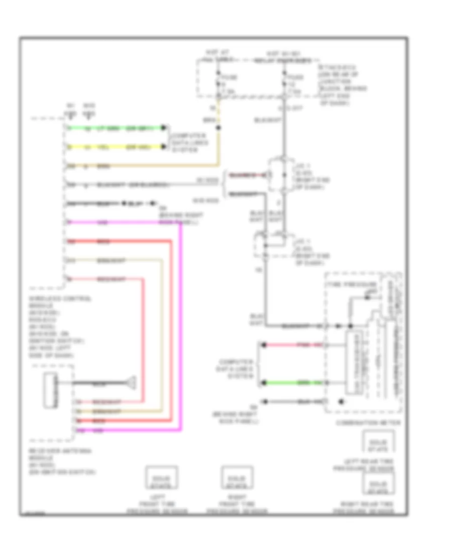
Forced Entry Wiring Diagram, Except Evolution (1 of 2) for Mitsubishi Lancer ES 2014
List of elements for Forced Entry Wiring Diagram, Except Evolution (1 of 2) for Mitsubishi Lancer ES 2014:
- (behind instrument cluster) g5
- C-301
- C-312
- C-313
- C-317
- Can drive circuit
- D-15
- Etacs-ecu (on rear of junction block, behind left end of dash)
- F-23
- F-30
- Fuse 15a
- Fuse 7.5a
- G10 (at left "c" pillar)
- G21 (on liftgate)
- G4 (behind right kick panel)
- Hatchback
- Headlights system
- Horns system
- Hot at all times
- Hot w/ ig1 relay energized
- Interface circuit
- J/c 1 (c-03) (right end of dash)
- J/c can 1 (c-06) (left side of dash)
- Keyless entry receiver
- Kos-ecu (w/ keyless entry) (left side of dash)
- Liftgate switch (center of liftgate)
- Nca
- Receiver antenna module (on ignition switch)
- Receiver keyless entry
- Red
- Sedan
- Trunk lid lock actuator (center rear of trunk lid)
- Wireless control module (w/o keyless entry) (on ignition switch)
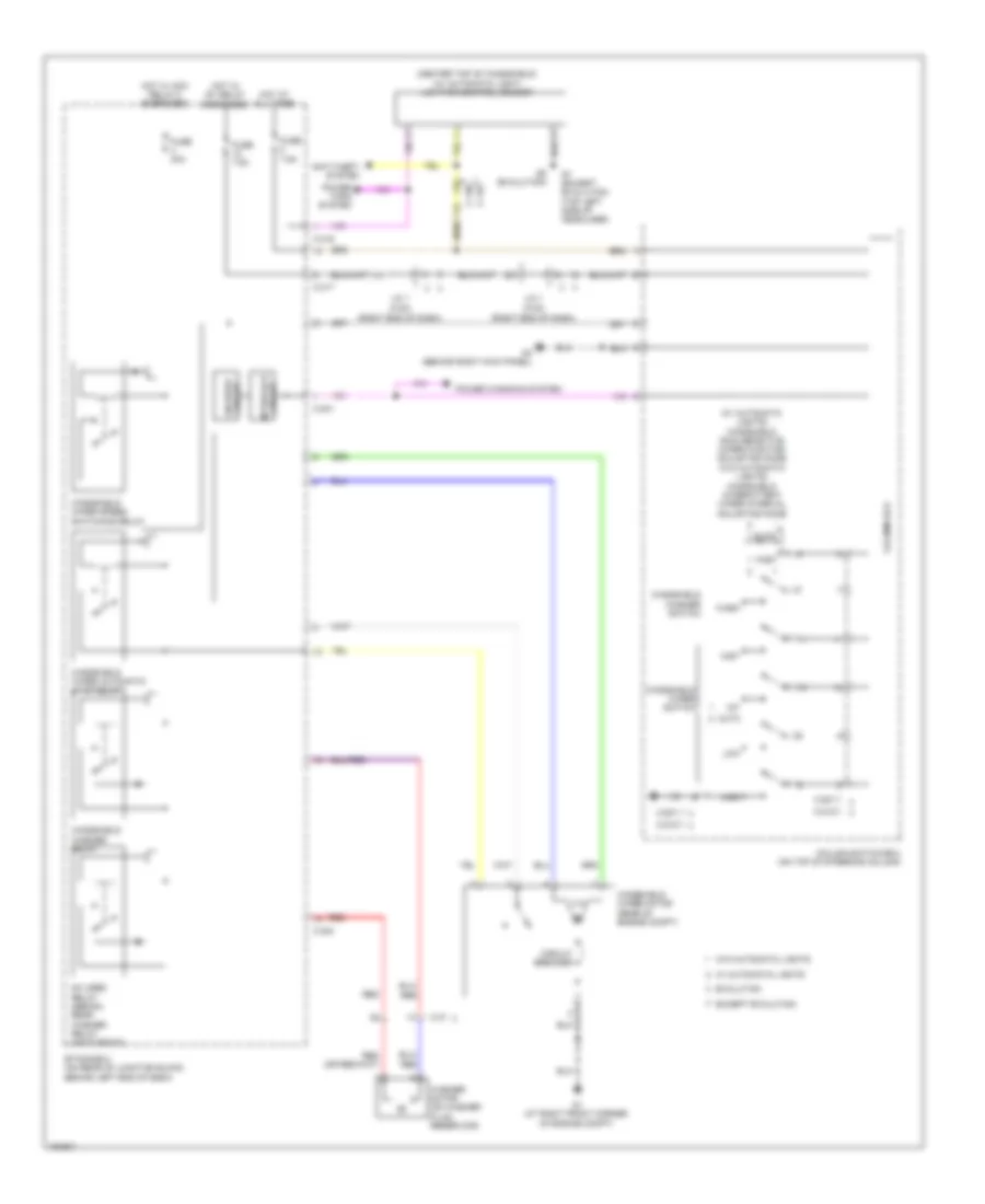
Forced Entry Wiring Diagram, Except Evolution (2 of 2) for Mitsubishi Lancer ES 2014
List of elements for Forced Entry Wiring Diagram, Except Evolution (2 of 2) for Mitsubishi Lancer ES 2014:
- Can transceiver circuit
- Center panel unit
- Combination meter
- Computer data lines system
- Cpu
- Lcd (theft-alarm indicator)
- Left front door switch (in left "b" pillar)
- Left rear door switch (in left "c" pillar)
- Pnk
- Red
- Right front door switch (in right "b" pillar)
- Right rear door switch (in right "c" pillar)
- Theft-alarm indicator
- Tone alarm
Immobilizer Wiring Diagram, Evolution for Mitsubishi Lancer ES 2014
List of elements for Immobilizer Wiring Diagram, Evolution for Mitsubishi Lancer ES 2014:
- B-10
- C-307
- C-317
- Computer data lines system
- Door locks system
- Engine compartment relay box (left side of engine compt)
- Engine control module (left rear of engine compt)
- Engine controls system
- Etacs-ecu (on rear of junction block, behind left end of dash)
- Fuse 10a
- Fuse 20a
- Fuse 30a
- Fuse 7.5a
- G4 (behind right kick panel)
- Hot at all times
- Hot w/ ig1 relay energized
- Id code (transponder)
- Immobilizer antenna
- J/c 1 (c-101)
- Kos-ecu (w/ keyless entry) (left side of dash)
- Mfi relay
- Pnk
- Receiver antenna module (on ignition switch)
- Red
- Wireless control module (w/o keyless entry) (on ignition switch)
Immobilizer Wiring Diagram, Except Evolution for Mitsubishi Lancer ES 2014
List of elements for Immobilizer Wiring Diagram, Except Evolution for Mitsubishi Lancer ES 2014:
- (left side of engine compt)
- B-109
- C-307
- C-317
- Computer data lines system
- Engine compartment relay box
- Engine control module (left rear of engine compt)
- Engine controls system
- Etacs-ecu (on rear of junction block, behind left end of dash)
- Fuse 10a
- Fuse 30a
- Fuse 7.5a
- G4 (behind right kick panel)
- Hot at all times
- Hot w/ ig1 relay energized
- Id code (transponder)
- Immobilizer antenna
- J/c 1 (c-03) (right end of dash)
- Kos-ecu (w/ keyless entry) (left side of dash)
- Mfi relay
- Pnk
- Receiver antenna module (on ignition switch)
- Red
- Wireless control module (w/o keyless entry) (on ignition switch)
BODY CONTROL MODULES
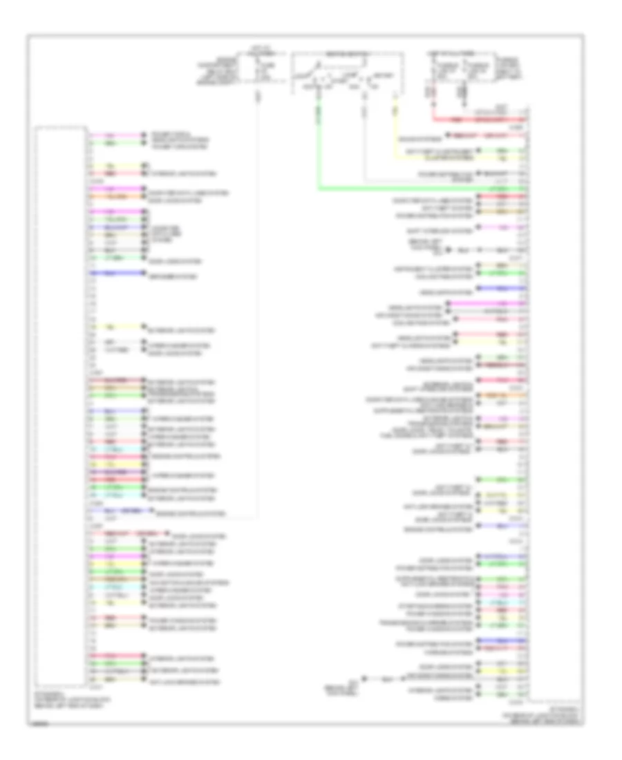
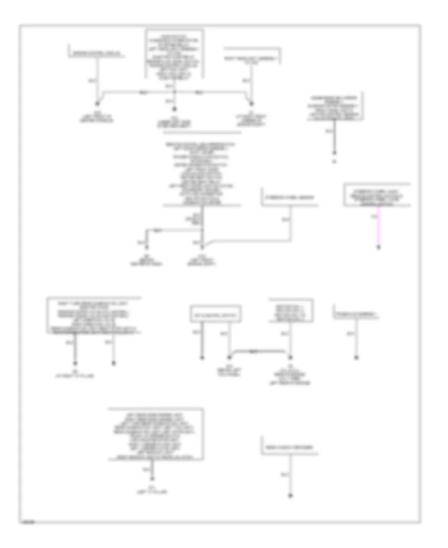
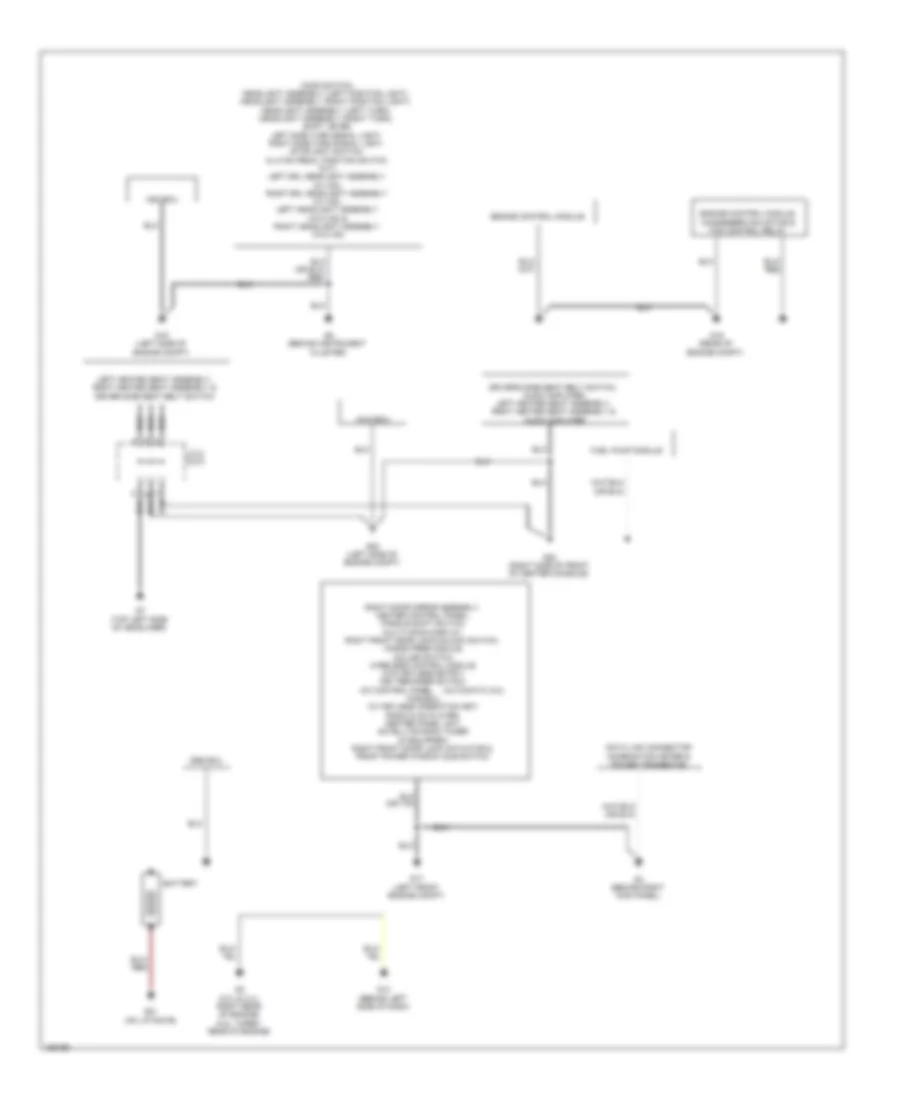
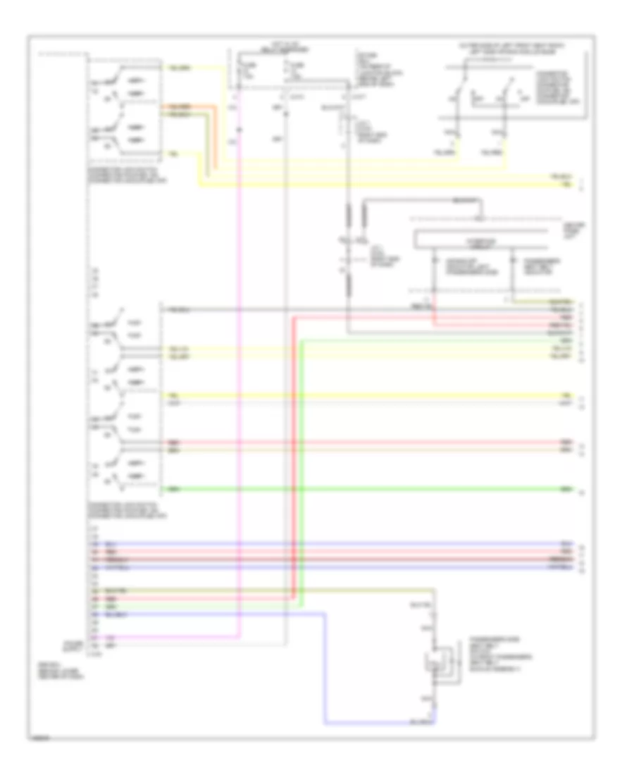
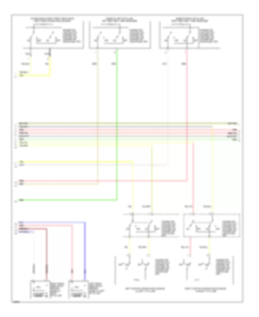
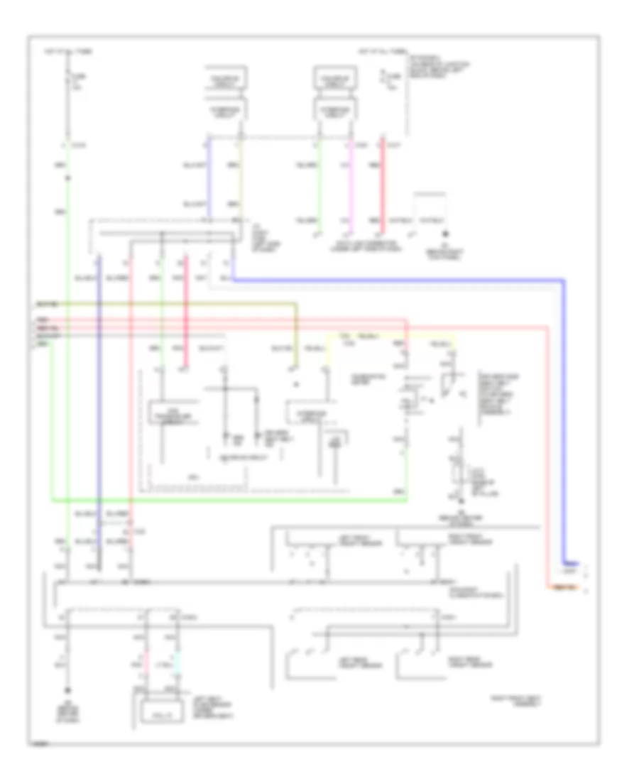
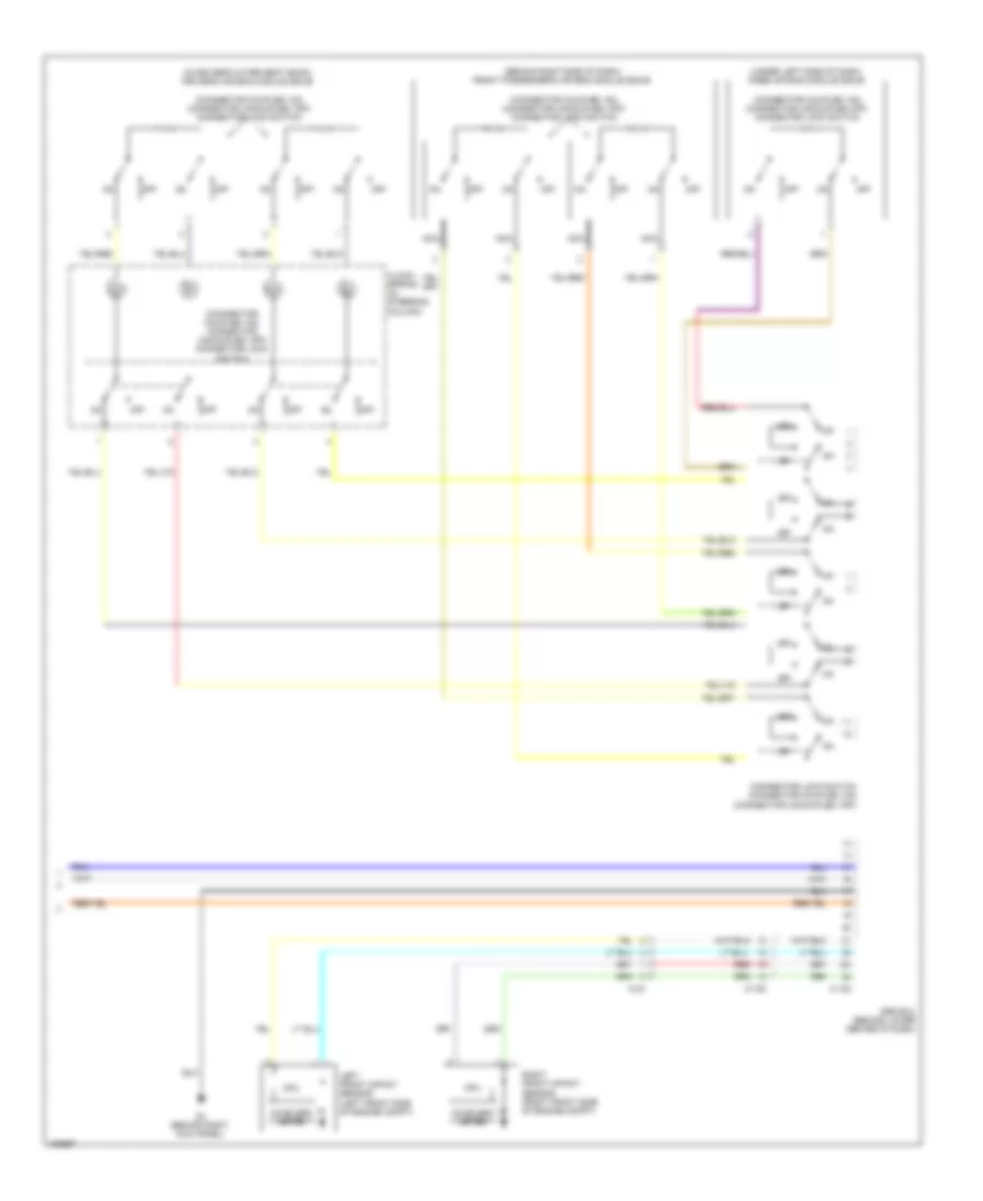
Body Control Modules Wiring Diagram, Evolution for Mitsubishi Lancer ES 2014
List of elements for Body Control Modules Wiring Diagram, Evolution for Mitsubishi Lancer ES 2014:
- Acc
- Air conditioning system
- Anti theft systems
- Anti-lock brakes system
- Anti-theft & horn systems
- Anti-theft & warning systems
- Anti-theft system
- C-301
- C-304
- C-307
- C-309
- C-311
- C-312
- C-313
- C-314
- C-315
- C-316
- C-317
- Computer data lines system
- Cooling fans system
- Defogger system
- Door locks & anti-theft systems
- Door locks & trunk, tailgate, fuel doors systems
- Door locks system
- Engine compartment relay box (left side of engine compt)
- Engine controls system
- Etacs-ecu (on rear of junction block, behind left end of dash)
- Exterior lights & shift interlock systems
- Exterior lights system
- Fuse 30a
- Fusible link 34 80a
- Fusible link 37 80a
- Fusible link box (near to battery)
- G18 (left front engine compt)
- Headlights system
- Horns system
- Hot at all times
- Ignition switch
- Instrument cluster &
- Instrument cluster system
- Interior lights system
- Lock
- Mirrors system
- Pnk
- Power distribution system
- Power tops & headlights systems
- Power tops system
- Power windows system
- Red
- Shift interlock system
- Sound & mirrors systems
- Sound systems
- Start
- Starting/charging system
- Trunk, tailgate, fuel doors system
- Wiper/washer system
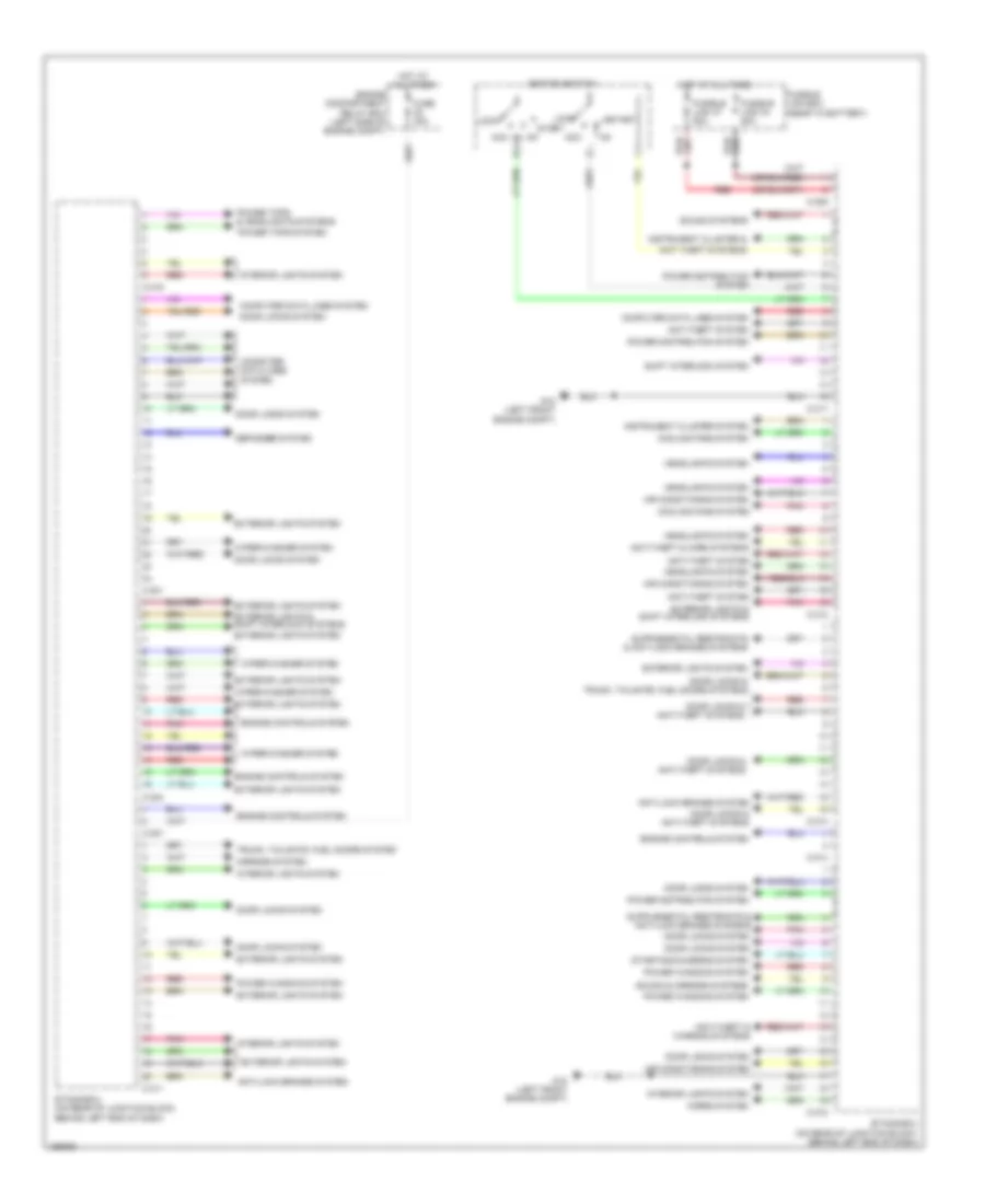
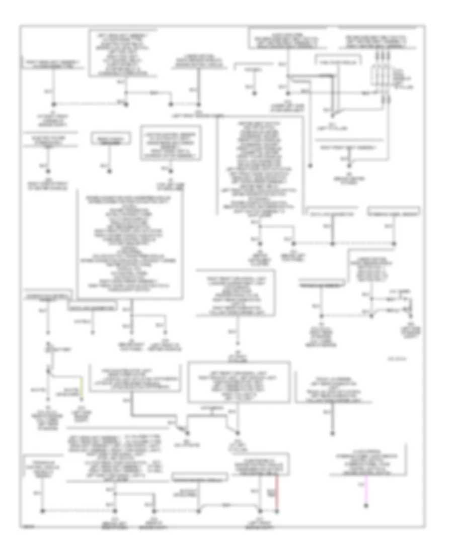
Body Control Modules Wiring Diagram, Except Evolution for Mitsubishi Lancer ES 2014
List of elements for Body Control Modules Wiring Diagram, Except Evolution for Mitsubishi Lancer ES 2014:
- (behind left kick panel) g14
- Acc
- Air conditioning system
- Anti-lock brakes system
- Anti-theft & door locks systems
- Anti-theft & horns systems
- Anti-theft & instrument
- Anti-theft system
- C-301
- C-304
- C-307
- C-309
- C-311
- C-312
- C-313
- C-314
- C-315
- C-316
- C-317
- Cluster systems
- Computer data lines system
- Cooling fans system
- Defogger system
- Door locks system
- Door locks, trunk, tailgate, fuel doors & anti-theft systems
- Engine compartment relay box (left side of engine compt)
- Engine controls system
- Etacs-ecu (on rear of junction block, behind left end of dash)
- Exterior lights & shift interlock systems
- Exterior lights & transmissions systems
- Exterior lights system
- Fuse 30a
- Fusible link 34 80a
- Fusible link 37 80a
- Fusible link box (next to battery)
- G14 (behind left kick panel)
- Headlights system
- Horns system
- Hot at all times
- Ignition switch
- Instrument cluster system
- Interior lights system
- Lock
- Navigation & sound systems
- Pnk
- Power distribution system
- Power tops & headlights systems
- Power tops system
- Power windows system
- Red
- Shift interlock system
- Sound systems
- Start
- Starting/charging system
- Transmissions & mirrors systems
- Warning systems
- Wiper/washer system
COMPUTER DATA LINES
2.0L
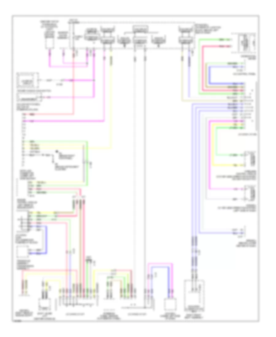
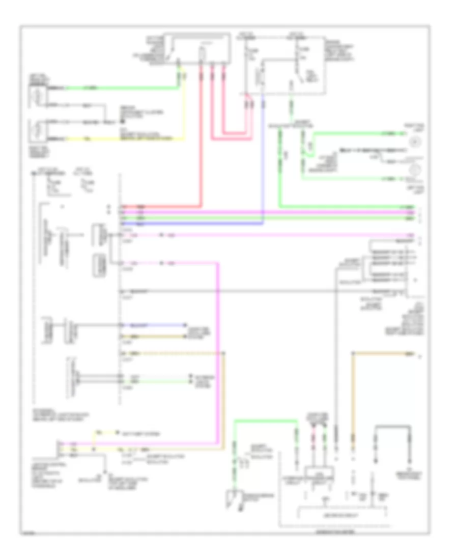
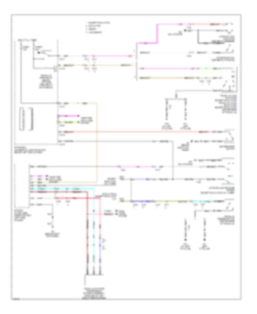
2.0L, Computer Data Lines Wiring Diagram for Mitsubishi Lancer ES 2014
List of elements for 2.0L, Computer Data Lines Wiring Diagram for Mitsubishi Lancer ES 2014:
- (not used)
- (w/ asc)
- (w/o asc)
- A/c control panel (automatic a/c) heater control unit (manual a/c) (behind center of dash)
- Abs-ecu (w/o asc) asc-ecu (w/ asc) (w/o asc: right rear corner of engine compt) (w/ asc: right rear of engine compt)
- Analog interface circuit
- Automatic a/c
- Awd ecu (2.4l) (under left side of dash)
- B-109
- C-122
- C-126
- C-127
- C-141
- C-144
- C-146
- C-147
- C-22
- C-301
- C-316
- C-317
- C-35
- C-41
- Can drive circuit
- Can transceiver circuit
- Circuit can drive
- Column ecu
- Column switch-ecu (on top of steering column)
- Combination meter
- Cpu
- D-35-2
- Data link connector (under left side of dash)
- Electric power steering-ecu (right kick panel)
- Engine control module (left rear of engine compt)
- Etacs-ecu (on rear of junction block, behind left end of dash)
- Fuse 5 10a
- G4 (behind right kick panel)
- G5 (behind instrument cluster)
- Hot at all times
- Interface circuit
- J/c (can1) (c-06) (left side of dash)
- J/c (can2) (c-05) (left side of dash)
- J/c (can3) (c-124)
- Kos-ecu (w/ keyless operating system) (left side of dash)
- Lighting control sensor (center top of windshield)
- Lin drive circuit
- Manual a/c
- Nca
- Occupant classification ecu
- Pnk
- Power window main switch
- Red
- Right front seat assembly
- Srs-ecu (behind lower center of dash)
- Steering wheel sensor (w/ asc) (in steering wheel)
- Sunroof motor assembly
- Transaxle control module (behind left end of dash)
- Wireless control module (w/o keyless operating system) (on ignition switch)
2.0L TURBO
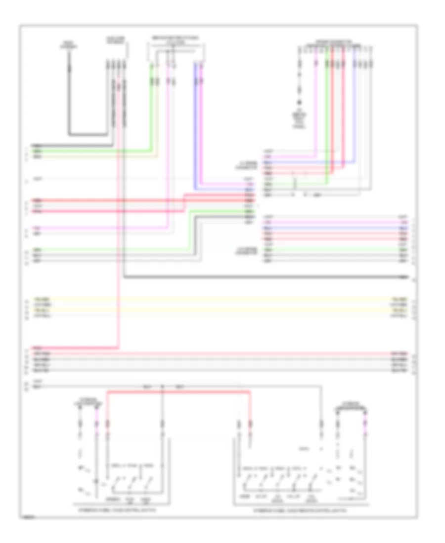
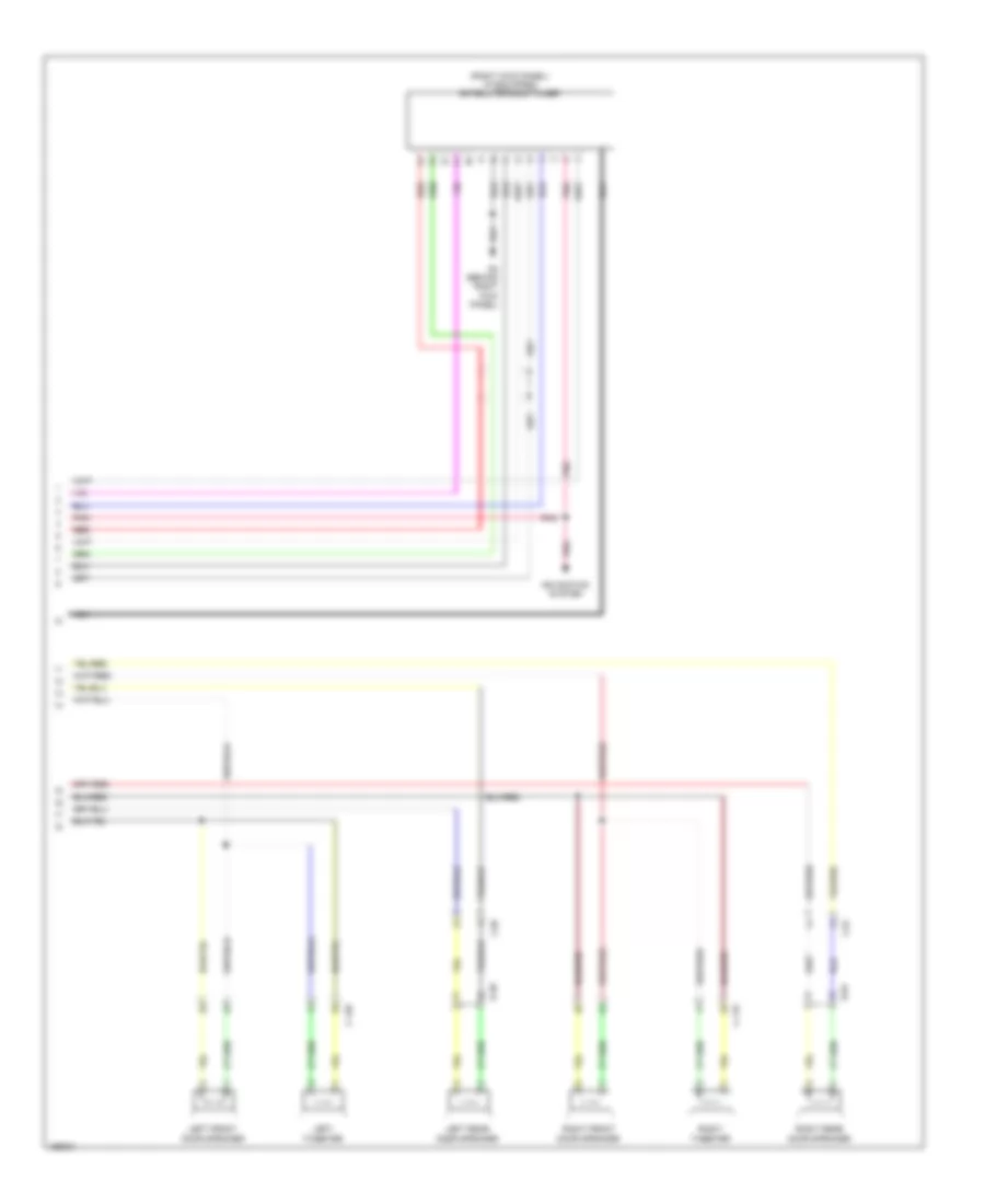
2.0L Turbo, Computer Data Lines Wiring Diagram, Evolution for Mitsubishi Lancer ES 2014
List of elements for 2.0L Turbo, Computer Data Lines Wiring Diagram, Evolution for Mitsubishi Lancer ES 2014:
- (center top of windshield) (w/ automatic light) lighting control sensor
- (not used)
- A-13
- A/c control panel
- A/t
- Analog interface circuit
- Asc-ecu (right rear of engine compt)
- Awc-ecu (under left side of dash)
- B-10
- C-123
- C-129
- C-130
- C-19
- C-23
- C-27
- C-301
- C-316
- C-317
- C-37
- C-41
- Can drive circuit
- Can transceiver circuit
- Circuit can drive
- Column ecu
- Column switch-ecu (on top of steering column)
- Combination meter
- Cpu
- D-39-2
- Data link connector (under left side of dash)
- Engine control module (left rear of engine compt)
- Etacs ecu (on rear of junction block, behind left end of dash)
- Fuse 5 10a
- G4 (behind right kick panel)
- G5 (behind instrument cluster)
- Hot at all times
- Interface circuit
- J/c (can1) (c-105)
- J/c (can2) (c-127)
- J/c (can3) (c-127)
- J/c (can4) (a-55) (on underhood fuse/relay block)
- Kos-ecu (w/ keyless operating system) (left side of dash)
- Lin drive circuit
- M/t
- Nca
- Occupant classification ecu
- Pnk
- Power window main switch
- Red
- Right front seat assembly
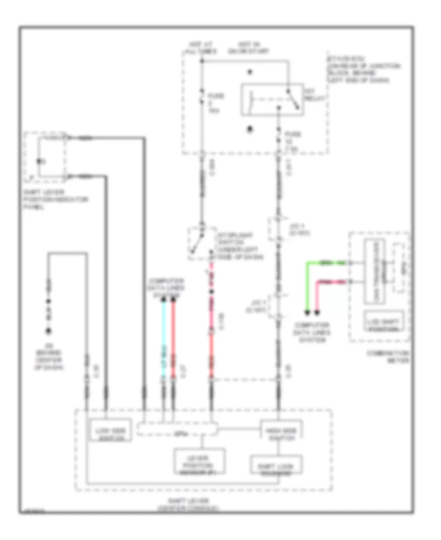
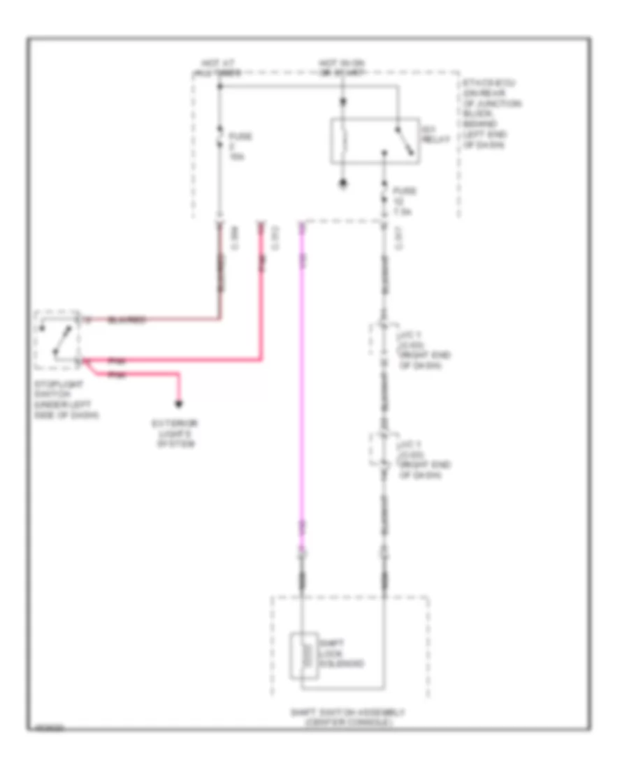
- Shift lever (a/t) (center console)
- Srs-ecu (behind lower center of dash)
- Steering wheel sensor (in steering wheel)
- Sunroof motor assembly
- Transaxle assembly (transmission assembly)
- Wireless control module (w/o keyless operating system) (on ignition switch)
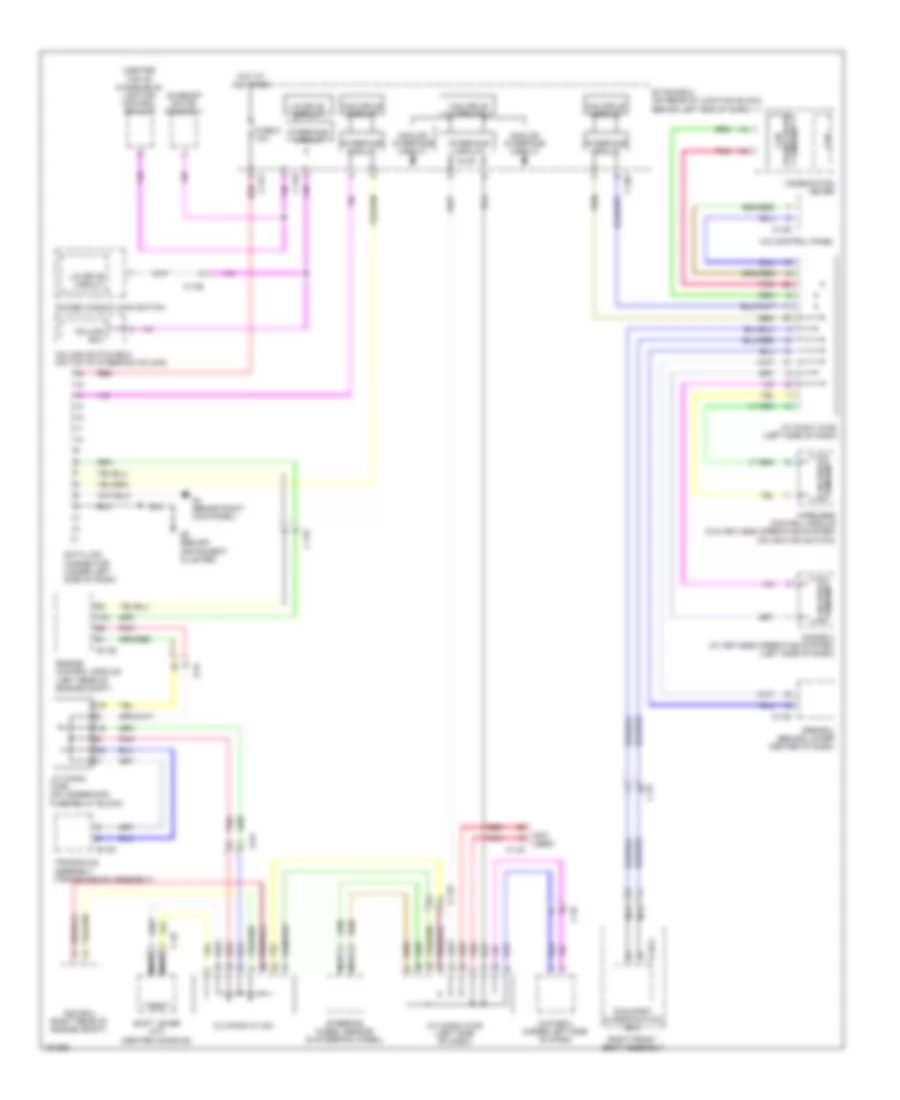
2.0L Turbo, Computer Data Lines Wiring Diagram, Except Evolution for Mitsubishi Lancer ES 2014
List of elements for 2.0L Turbo, Computer Data Lines Wiring Diagram, Except Evolution for Mitsubishi Lancer ES 2014:
- (center top of windshield) lighting control sensor
- (not
- A-54
- A/c control panel
- Analog interface circuit
- Asc-ecu (right rear of engine compt)
- Awc-ecu (under left side of dash)
- B-109
- B-120
- C-122
- C-126
- C-127
- C-144
- C-146
- C-22
- C-301
- C-316
- C-317
- C-35
- C-49
- Can drive circuit
- Can transceiver circuit
- Circuit can drive
- Column ecu
- Column switch-ecu (on top of steering column)
- Combination meter
- Cpu
- D-35-2
- Data link connector (under left side of dash)
- Engine control module (left rear of engine compt)
- Etacs-ecu (on rear of junction block, behind left end of dash)
- Fuse 5 10a
- G4 (behind right kick panel)
- G5 (behind instrument cluster)
- Hot at all times
- Interface circuit
- J/c (can1) (c-06) (left side of dash)
- J/c (can2) (c-05) (left side of dash)
- J/c (can3) (c-124)
- J/c (can4) (a-55) (on underhood fuse/relay block)
- Kos-ecu (w/ keyless operating system) (left side of dash)
- Lin drive circuit
- Nca
- Occupant classification ecu
- Pnk
- Power window main switch
- Red
- Right front seat assembly
- Shift lever (a/t) (center console)
- Srs-ecu (behind lower center of dash)
- Steering wheel sensor (in steering wheel)
- Sunroof motor assembly
- Transaxle assembly (transmission assembly)
- Used)
- Wireless control module (w/o keyless operating system) (on ignition switch)
2.4L
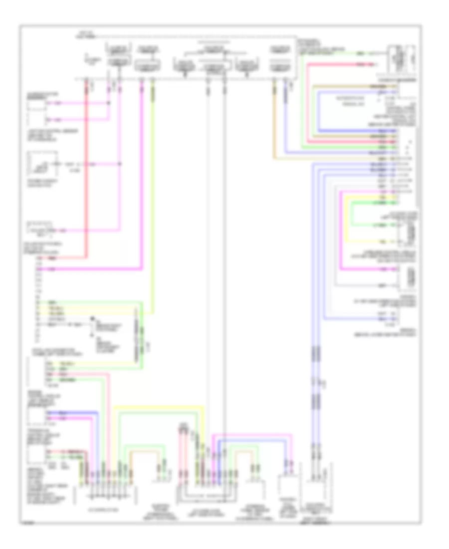
2.4L, Computer Data Lines Wiring Diagram for Mitsubishi Lancer ES 2014
List of elements for 2.4L, Computer Data Lines Wiring Diagram for Mitsubishi Lancer ES 2014:
- (not used)
- (w/ asc)
- (w/o asc)
- A/c control panel (automatic a/c) heater control unit (manual a/c) (behind center of dash)
- Abs-ecu (w/o asc) asc-ecu (w/ asc) (w/o asc: right rear corner of engine compt) (w/ asc: right rear of engine compt)
- Analog interface circuit
- Automatic a/c
- Awd ecu (2.4l) (under left side of dash)
- B-109
- C-122
- C-126
- C-127
- C-141
- C-144
- C-146
- C-147
- C-22
- C-301
- C-316
- C-317
- C-35
- C-41
- Can drive circuit
- Can transceiver circuit
- Circuit can drive
- Column ecu
- Column switch-ecu (on top of steering column)
- Combination meter
- Cpu
- D-35-2
- Data link connector (under left side of dash)
- Electric power steering-ecu (right kick panel)
- Engine control module (left rear of engine compt)
- Etacs-ecu (on rear of junction block, behind left end of dash)
- Fuse 5 10a
- G4 (behind right kick panel)
- G5 (behind instrument cluster)
- Hot at all times
- Interface circuit
- J/c (can1) (c-06) (left side of dash)
- J/c (can2) (c-05) (left side of dash)
- J/c (can3) (c-124)
- Kos-ecu (w/ keyless operating system) (left side of dash)
- Lighting control sensor (center top of windshield)
- Lin drive circuit
- Manual a/c
- Nca
- Occupant classification ecu
- Pnk
- Power window main switch
- Red
- Right front seat assembly
- Srs-ecu (behind lower center of dash)
- Steering wheel sensor (w/ asc) (in steering wheel)
- Sunroof motor assembly
- Transaxle control module (behind left end of dash)
- Wireless control module (w/o keyless operating system) (on ignition switch)
COOLING FAN
2.0L
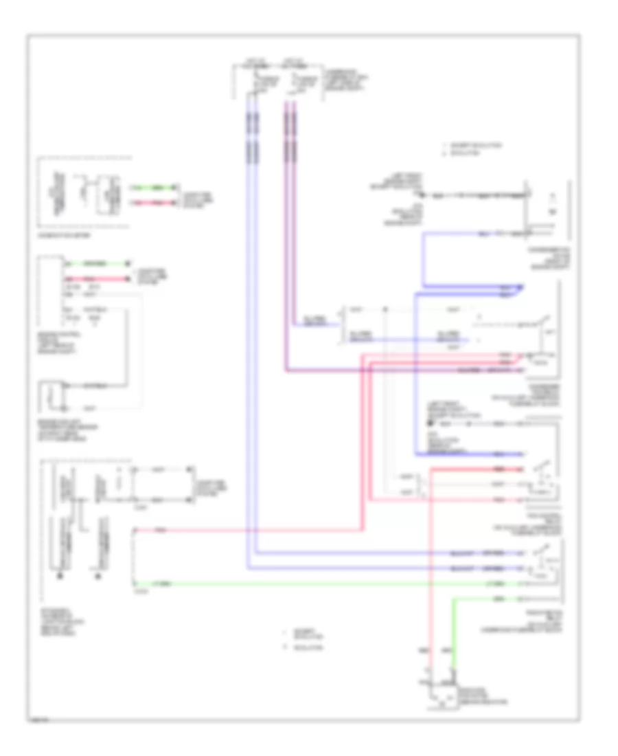
2.0L, Cooling Fan Wiring Diagram for Mitsubishi Lancer ES 2014
List of elements for 2.0L, Cooling Fan Wiring Diagram for Mitsubishi Lancer ES 2014:
- (engine coolant lcd
- (left front engine compt) g17
- Analog interface circuit
- B-108
- B-109
- C-301
- C-312
- Can
- Can drive circuit
- Combination meter
- Computer data lines system
- Condenser fan motor (front of engine compt)
- Condenser fan relay (on underhood fuse/relay block)
- Cpu
- Engine control module (left rear of engine compt)
- Engine coolant temperature sensor (on right rear of cylinder head)
- Etacs-ecu (on rear of junction block, behind left end of dash)
- Fan control relay (on underhood fuse/relay block)
- Fusible link 28 30a
- Fusible link 29 40a
- Hot at all times
- Interface circuit
- Nca
- Pnk
- Radiator fan motor (behind radiator)
- Radiator fan relay (on underhood fuse/relay block)
- Red
- Temperature)
- Transceiver circuit
- Underhood fuse/relay box (left side of engine compt)
2.0L TURBO
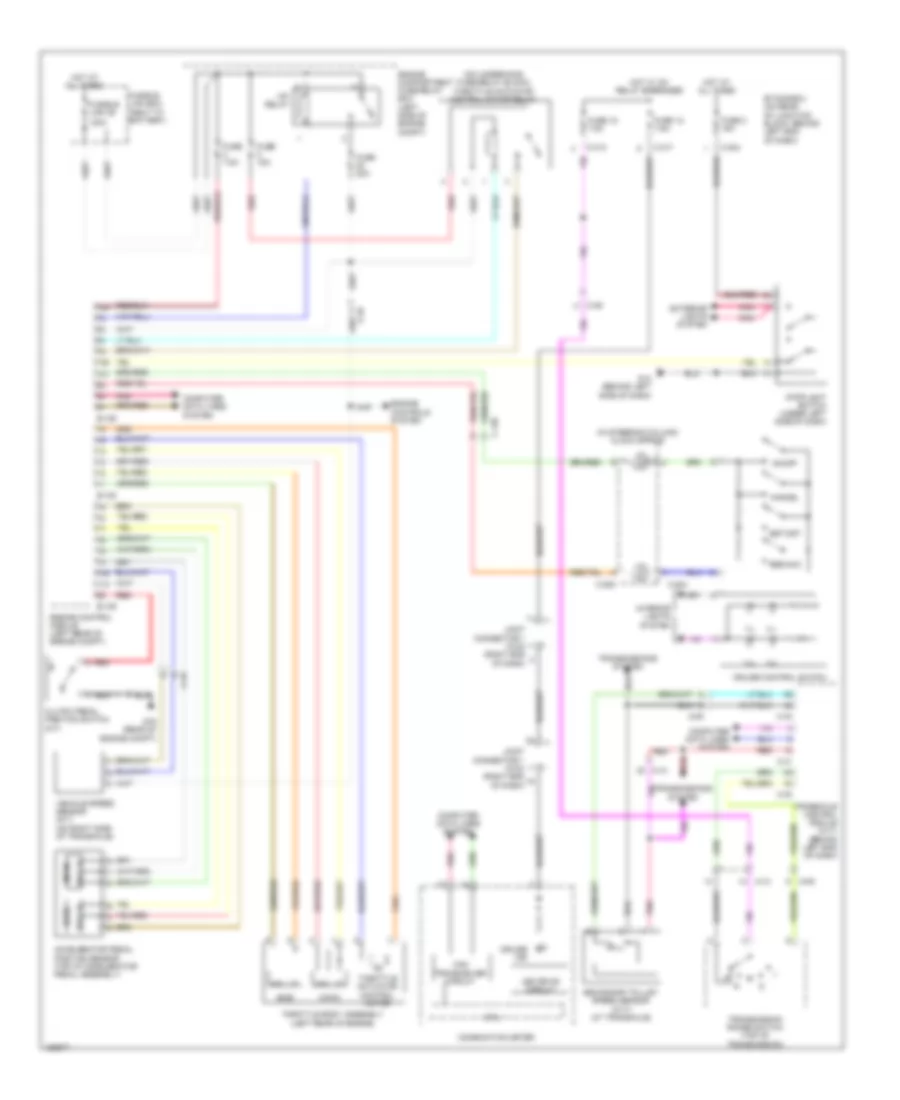
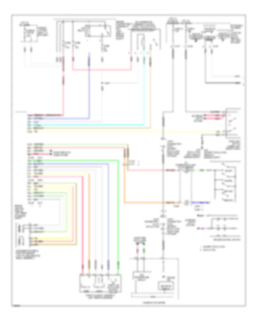
2.0L Turbo, Cooling Fan Wiring Diagram for Mitsubishi Lancer ES 2014
List of elements for 2.0L Turbo, Cooling Fan Wiring Diagram for Mitsubishi Lancer ES 2014:
- (engine coolant lcd
- (left front engine compt) (except evolution) g17
- (or red)
- Analog interface
- B-09
- B-10
- B-108
- B-109
- C-301
- C-312
- Can
- Can drive circuit
- Circuit
- Circuit interface
- Combination meter
- Computer data lines system
- Condenser fan motor (front of engine compt)
- Condenser fan relay (on auxiliary underhood fuse/relay block)
- Cpu
- Engine control module (left rear of engine compt)
- Engine coolant temperature sensor (on right rear of cylinder head)
- Etacs-ecu (on rear of junction block, behind left end of dash)
- Evolution
- Except evolution
- Fan control relay (on auxiliary underhood fuse/relay block)
- Fusible link 28 30a
- Fusible link 29 40a
- G16 (evolution) (rear of engine compt)
- Hot at all times
- Nca
- Pnk
- Radiator fan motor (behind radiator)
- Radiator fan relay (on auxiliary underhood fuse/relay block)
- Red
- Temperature)
- Transceiver circuit
- Underhood fuse/relay box (left side of engine compt)
2.4L
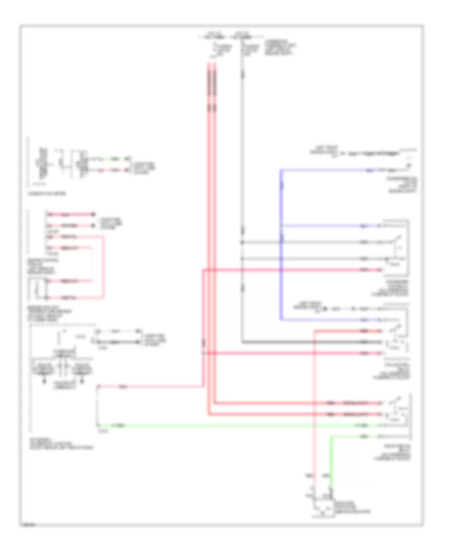
2.4L, Cooling Fan Wiring Diagram for Mitsubishi Lancer ES 2014
List of elements for 2.4L, Cooling Fan Wiring Diagram for Mitsubishi Lancer ES 2014:
- (engine coolant lcd
- (left front engine compt) g17
- Analog interface circuit
- B-108
- B-109
- C-301
- C-312
- Can
- Can drive circuit
- Combination meter
- Computer data lines system
- Condenser fan motor (front of engine compt)
- Condenser fan relay (on underhood fuse/relay block)
- Cpu
- Engine control module (left rear of engine compt)
- Engine coolant temperature sensor (on right rear of cylinder head)
- Etacs-ecu (on rear of junction block, behind left end of dash)
- Fan control relay (on underhood fuse/relay block)
- Fusible link 28 30a
- Fusible link 29 40a
- Hot at all times
- Interface circuit
- Nca
- Pnk
- Radiator fan motor (behind radiator)
- Radiator fan relay (on underhood fuse/relay block)
- Red
- Temperature)
- Transceiver circuit
- Underhood fuse/relay box (left side of engine compt)
CRUISE CONTROL
2.0L
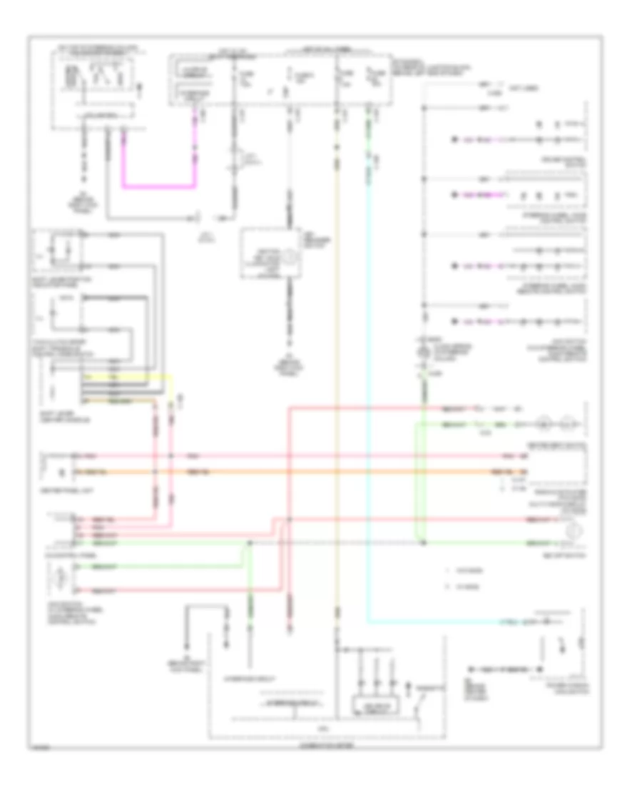
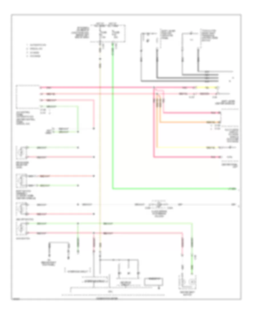
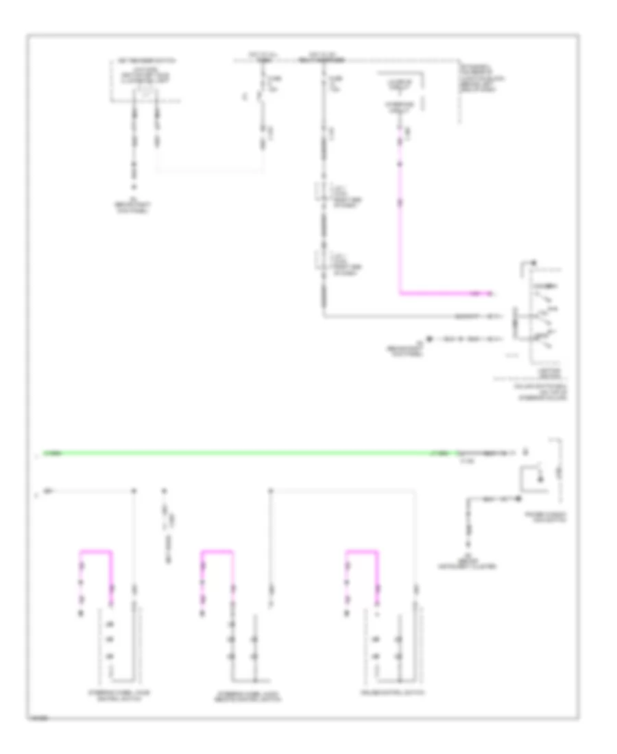
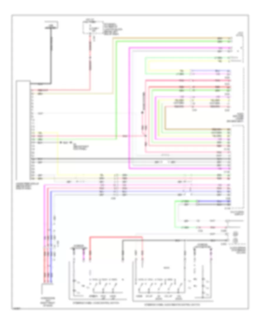
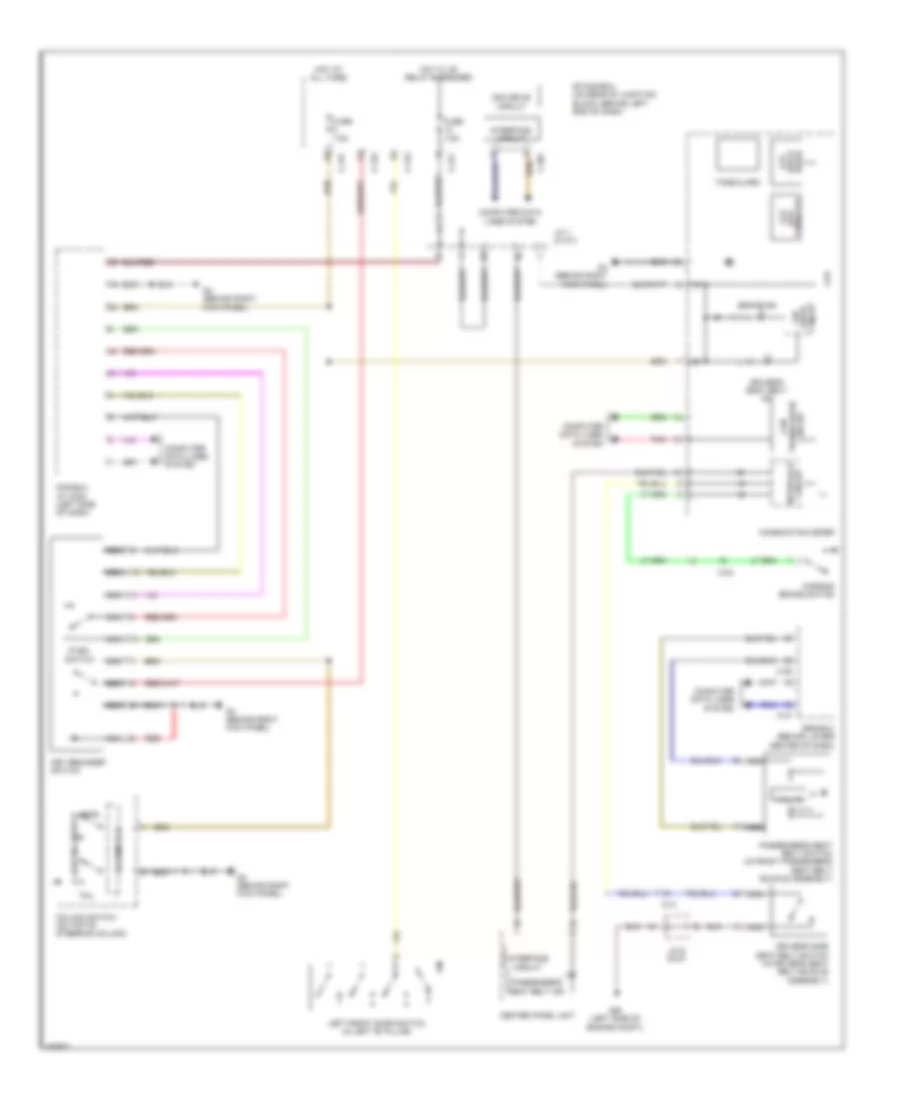
2.0L, Cruise Control Wiring Diagram for Mitsubishi Lancer ES 2014
List of elements for 2.0L, Cruise Control Wiring Diagram for Mitsubishi Lancer ES 2014:
- (in steering column) clock spring
- (main)
- (on underhood fuse/relay block) throttle actuator control motor relay
- (sub)
- 120a
- A-09
- A-10
- Accelerator pedal position sensor (top of accelerator pedal assembly)
- B-108
- B-109
- C-128
- C-204
- C-205
- C-304
- C-313
- C-317
- C-39
- C-40
- C-41
- Can transceiver circuit
- Cancel
- Clutch pedal position switch (m/t)
- Combination meter
- Computer data lines system
- Cpu
- Cruise control switch
- Cruise ind
- Engine compartment fuse/relay box (left side of engine compt)
- Engine control module (left rear of engine compt)
- Engine controls system
- Etacs-ecu (on rear of junction block, behind left end of dash)
- Exterior lights system
- Fuse 12 7.5a
- Fuse 15a
- Fuse 18 7.5a
- Fuse 2 15a
- Fuse 20a
- Fuse 7.5a
- Fusible link 36
- Fusible link box (next to battery)
- G13 (behind left side of dash)
- G16 (rear of engine compt)
- Hall ic
- Hot at all times
- Hot w/ ig1 relay energized
- Ill
- Interior lights system
- Joint connector 1 (c-03) (right end of dash)
- Led drive circuit
- Mfi relay
- On/off
- Pnk
- Red
- Res/acc
- Secondary pulley speed sensor (cvt) (at transaxle)
- Set/cst
- Stoplight switch (under left side of dash)
- Throttle actuator control motor
- Throttle body assembly (left rear of engine)
- Transaxle control module (cvt) (behind left end of dash)
- Transmission range switch (top of transmission)
- Transmissions system
- Vehicle speed sensor (m/t) (on right side of transaxle)
2.0L TURBO
2.0L Turbo, Cruise Control Wiring Diagram (1 of 2) for Mitsubishi Lancer ES 2014
List of elements for 2.0L Turbo, Cruise Control Wiring Diagram (1 of 2) for Mitsubishi Lancer ES 2014:
- (in steering column) clock spring
- (main)
- (on underhood fuse/relay block) throttle actuator control motor relay
- (sub)
- 120a
- Accelerator pedal position sensor (top of accelerator pedal assembly)
- Analog interface circuit
- B-09
- B-10
- B-108
- B-109
- C-128
- C-131
- C-202
- C-204
- C-205
- C-301
- C-304
- C-317
- Can drive circuit
- Can transceiver circuit
- Cancel
- Combination meter
- Computer data lines system
- Cpu
- Cruise control switch
- Cruise ind
- Engine compartment fuse/relay box (left side of engine compt)
- Engine control module (left rear of engine compt)
- Etacs-ecu (on rear of junction block, behind left end of dash)
- Evolution
- Except evolution
- Exterior lights system
- Fuse 12 7.5a
- Fuse 15a
- Fuse 2 15a
- Fuse 20a
- Fuse 7.5a
- Fusible link 36
- Fusible link box (next to battery)
- G16 (except evolution) (rear of engine compt)
- G19 (evolution) (left side of engine compt)
- Hall ic
- Hot at all times
- Hot w/ ig1 relay energized
- Ill
- Interface circuit
- Interior lights system
- Joint connector 1 (c-03) (except evolution) (right end of dash)
- Joint connector 1 (c-101) (evolution)
- Led drive circuit
- Mfi relay
- On/off
- Pnk
- Red
- Res/acc
- Set/cst
- Stoplight switch (under left side of dash)
- Throttle actuator control motor
- Throttle body assembly (left rear of engine)
2.0L Turbo, Cruise Control Wiring Diagram (2 of 2) for Mitsubishi Lancer ES 2014
List of elements for 2.0L Turbo, Cruise Control Wiring Diagram (2 of 2) for Mitsubishi Lancer ES 2014:
- (evolution)
- (or red)
- Abs-ecu (w/o asc) asc-ecu (w/ asc) (w/o asc: right rear corner of engine compt) (w/ asc: right rear of engine compt)
- C-127
- C-130
- C-39
- C-45
- C-47
- C-56
- D-11
- D-15
- Evolution
- Except evolution
- Joint connector c-05 (can2) (except evolution) (left side of dash)
- Joint connector c-104 (can2)
- Joint connector c-124 (can3) (except evolution) joint connector c-137 (can3) (evolution)
- Left front wheel speed sensor (on left front wheel hub assembly)
- Left rear wheel speed sensor (on left rear wheel hub assembly)
- Nca
- Pnk
- Red
- Right front wheel speed sensor (on right front wheel hub assembly)
- Right rear wheel speed sensor (on right rear wheel hub assembly)
- W/ asc
- W/o asc
2.4L
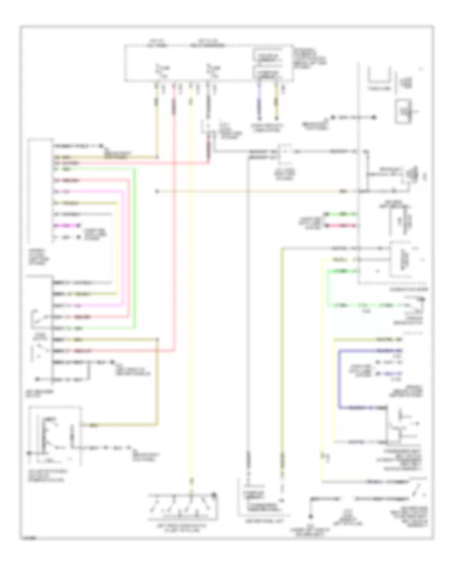
2.4L, Cruise Control Wiring Diagram for Mitsubishi Lancer ES 2014
List of elements for 2.4L, Cruise Control Wiring Diagram for Mitsubishi Lancer ES 2014:
- (in steering column) clock spring
- (main)
- (on underhood fuse/relay block) throttle actuator control motor relay
- (sub)
- 120a
- A-09
- A-10
- Accelerator pedal position sensor (top of accelerator pedal assembly)
- B-108
- B-109
- C-128
- C-204
- C-205
- C-304
- C-313
- C-317
- C-39
- C-40
- C-41
- Can transceiver circuit
- Cancel
- Clutch pedal position switch (m/t)
- Combination meter
- Computer data lines system
- Cpu
- Cruise control switch
- Cruise ind
- Engine compartment fuse/relay box (left side of engine compt)
- Engine control module (left rear of engine compt)
- Engine controls system
- Etacs-ecu (on rear of junction block, behind left end of dash)
- Exterior lights system
- Fuse 12 7.5a
- Fuse 15a
- Fuse 18 7.5a
- Fuse 2 15a
- Fuse 20a
- Fuse 7.5a
- Fusible link 36
- Fusible link box (next to battery)
- G13 (behind left side of dash)
- G16 (rear of engine compt)
- Hall ic
- Hot at all times
- Hot w/ ig1 relay energized
- Ill
- Interior lights system
- Joint connector 1 (c-03) (right end of dash)
- Led drive circuit
- Mfi relay
- On/off
- Pnk
- Red
- Res/acc
- Secondary pulley speed sensor (cvt) (at transaxle)
- Set/cst
- Stoplight switch (under left side of dash)
- Throttle actuator control motor
- Throttle body assembly (left rear of engine)
- Transaxle control module (cvt) (behind left end of dash)
- Transmission range switch (top of transmission)
- Transmissions system
- Vehicle speed sensor (m/t) (on right side of transaxle)
DEFOGGERS
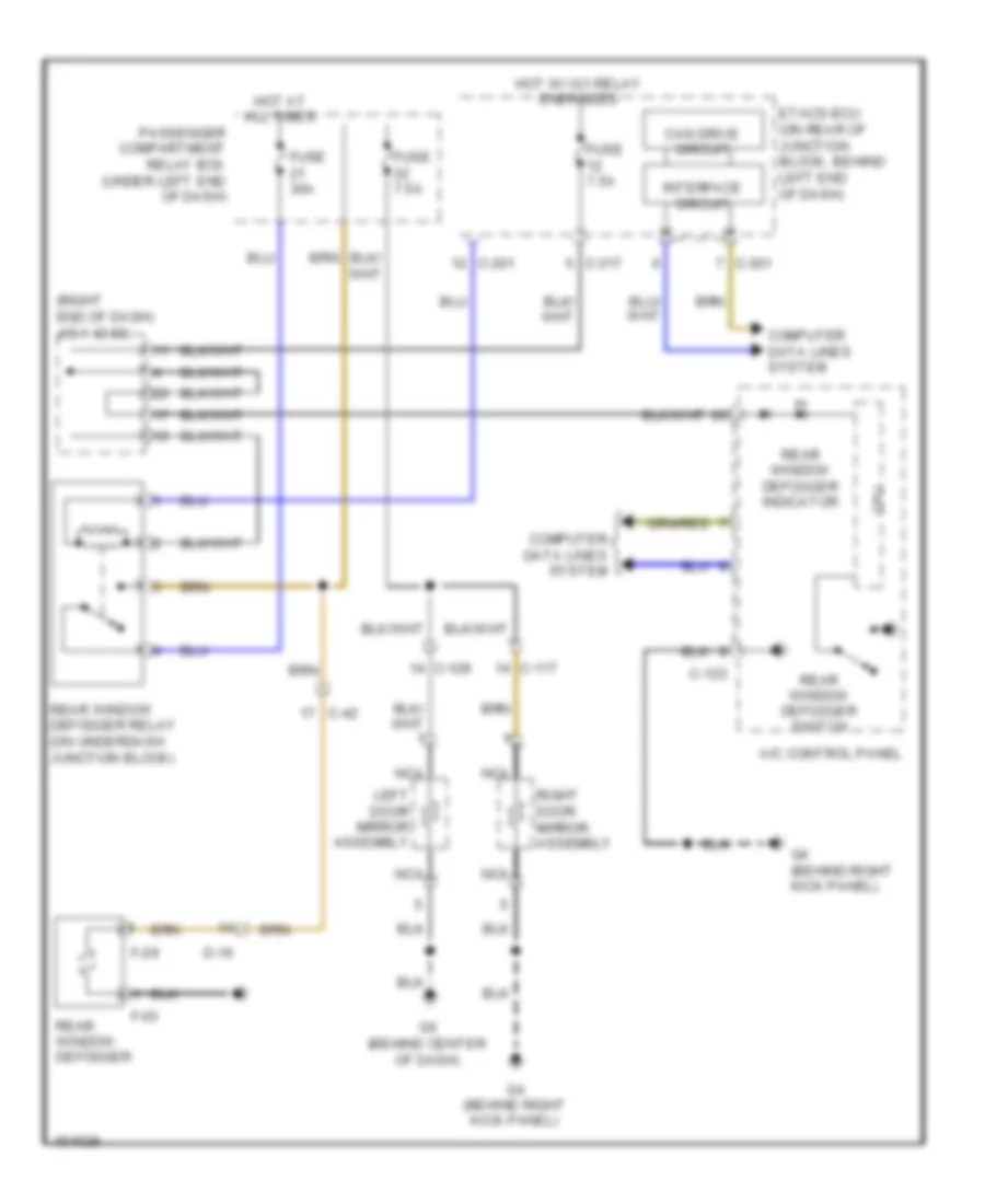
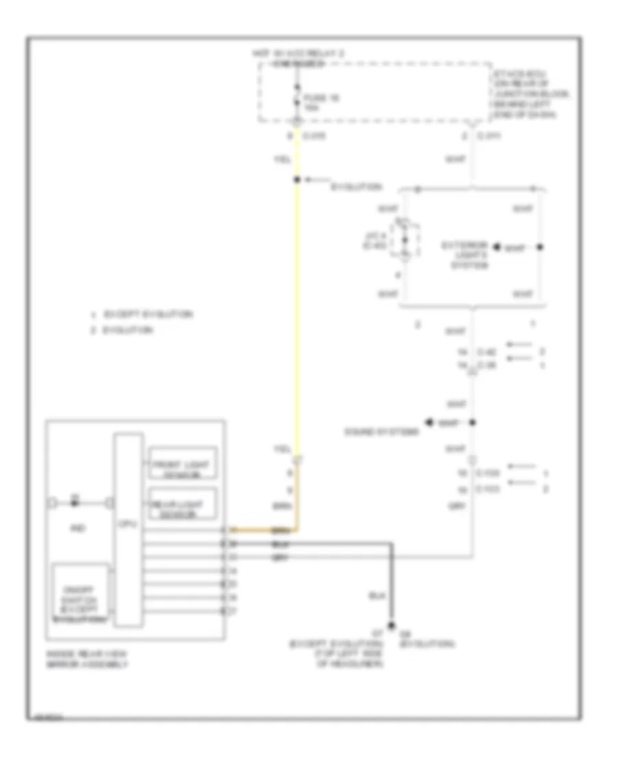
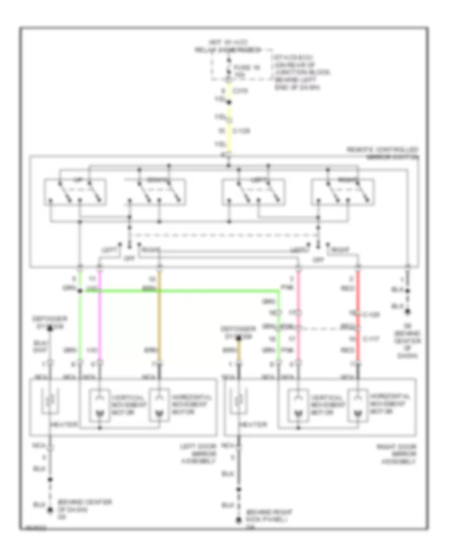
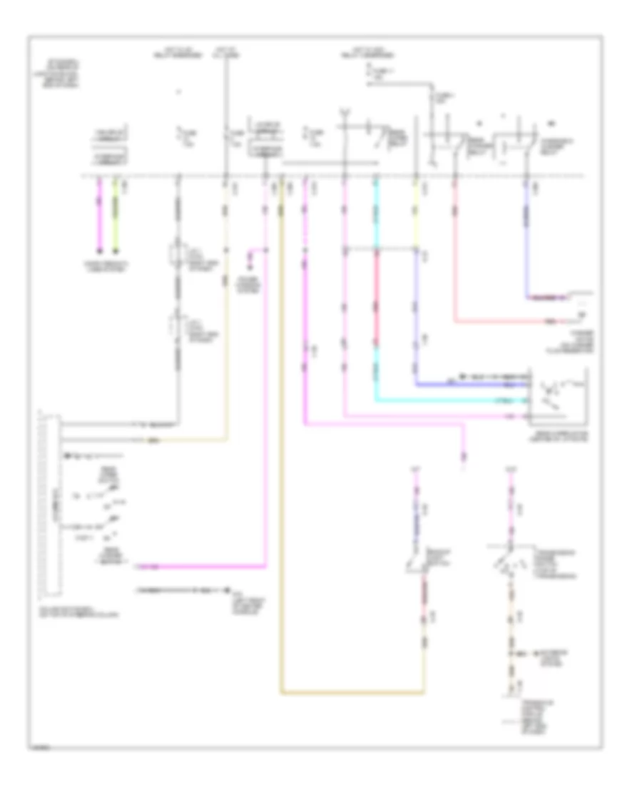
Defoggers Wiring Diagram, Evolution for Mitsubishi Lancer ES 2014
List of elements for Defoggers Wiring Diagram, Evolution for Mitsubishi Lancer ES 2014:
- (right end of dash) j/c 1 (c-03)
- A/c control panel
- C-117
- C-123
- C-129
- C-301
- C-317
- C-42
- Can drive circuit
- Computer data lines system
- Cpu
- D-16
- Etacs-ecu (on rear of junction block, behind left end of dash)
- F-03
- F-29
- Fuse 30a
- Fuse 7.5a
- G4 (behind right kick panel)
- G6 (behind center of dash)
- Hot at all times
- Hot w/ ig1 relay energized
- Interface circuit
- Left door mirror assembly
- Nca
- Passenger compartment relay box (under left end of dash)
- Rear window defogger
- Rear window defogger indicator
- Rear window defogger relay (on underdash junction block)
- Rear window defogger switch
- Right door mirror assembly
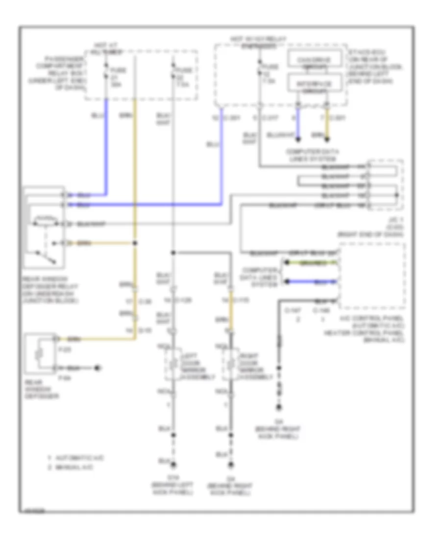
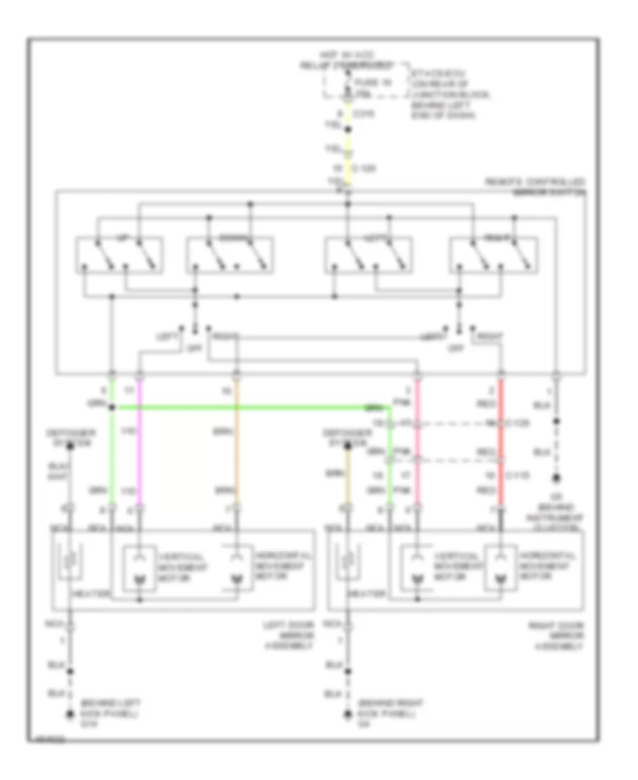
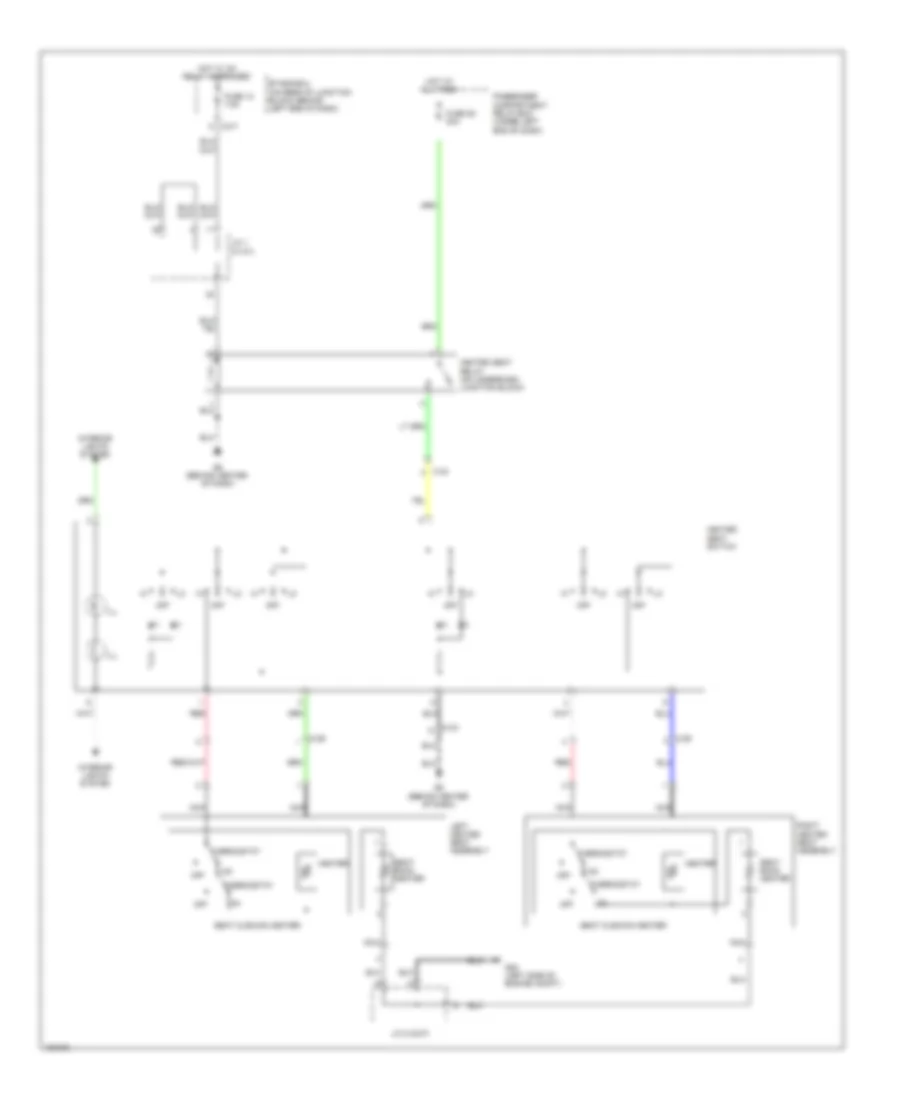
Defoggers Wiring Diagram, Except Evolution for Mitsubishi Lancer ES 2014
List of elements for Defoggers Wiring Diagram, Except Evolution for Mitsubishi Lancer ES 2014:
- A/c control panel (automatic a/c) heater control panel (manual a/c)
- Automatic a/c
- C-115
- C-126
- C-146
- C-147
- C-301
- C-317
- C-36
- Can drive circuit
- Computer data lines system
- D-15
- Etacs-ecu (on rear of junction block, behind left end of dash)
- F-04
- F-25
- Fuse 30a
- Fuse 7.5a
- G14 (behind left kick panel)
- G4 (behind right kick panel)
- Hot at all times
- Hot w/ ig1 relay energized
- Interface circuit
- J/c 1 (c-03) (right end of dash)
- Left door mirror assembly
- Manual a/c
- Nca
- Passenger compartment relay box (under left end of dash)
- Rear window defogger
- Rear window defogger relay (on underdash junction block)
- Right door mirror assembly
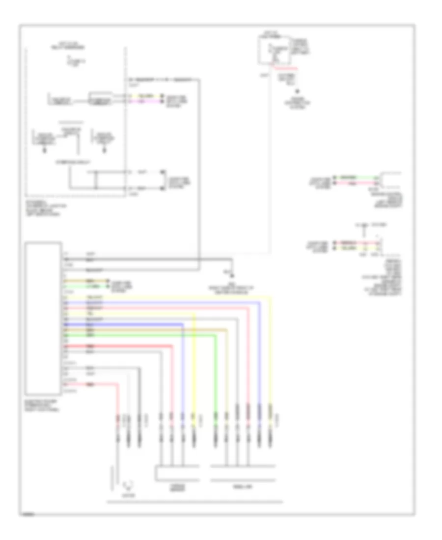
ELECTRONIC POWER STEERING
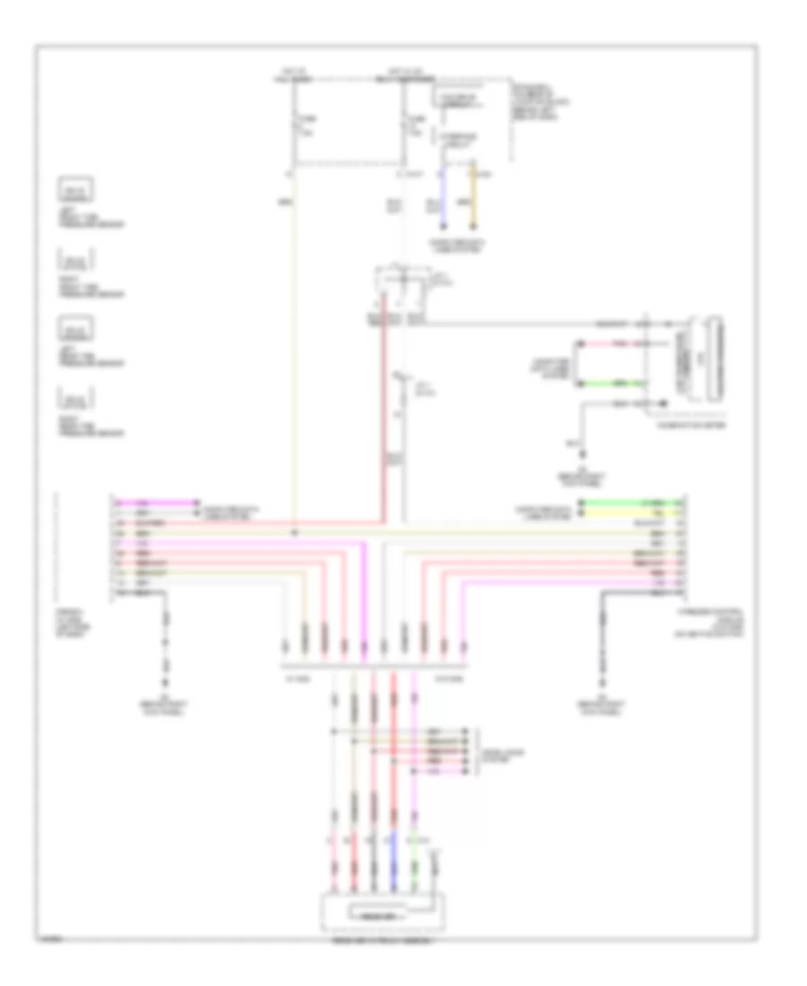
Electronic Power Steering Wiring Diagram for Mitsubishi Lancer ES 2014
List of elements for Electronic Power Steering Wiring Diagram for Mitsubishi Lancer ES 2014:
- A-03
- A-51
- Abs-ecu (w/o asc) asc-ecu (w/ asc) (w/o asc: right rear corner of engine compt) (w/ asc: right rear of engine compt)
- Analog interface circuit
- B-109
- C-141
- C-141-1
- C-141-2
- C-141-3
- C-141-4
- C-141-5
- C-141-6
- C-141-7
- C-301
- C-317
- C140
- Can drive circuit
- Computer data lines system
- Electric power steering ecu (right kick panel)
- Engine control module (left rear of engine compt)
- Etacs-ecu (on rear of junction block, behind left end of dash)
- Fuse 12 7.5a
- Fusible link 80a
- Fusible link box (next to battery)
- G22 (right side of front of center console)
- Hot at all times
- Hot w/ ig1 relay energized
- Interface circuit
- Motor
- Nca
- Pnk
- Power distribution system
- Red
- Resolver
- Torque sensor
- W/o asc w/ asc
ENGINE PERFORMANCE
2.0L
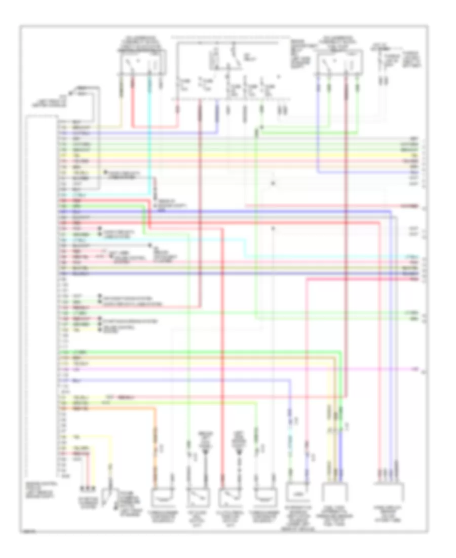
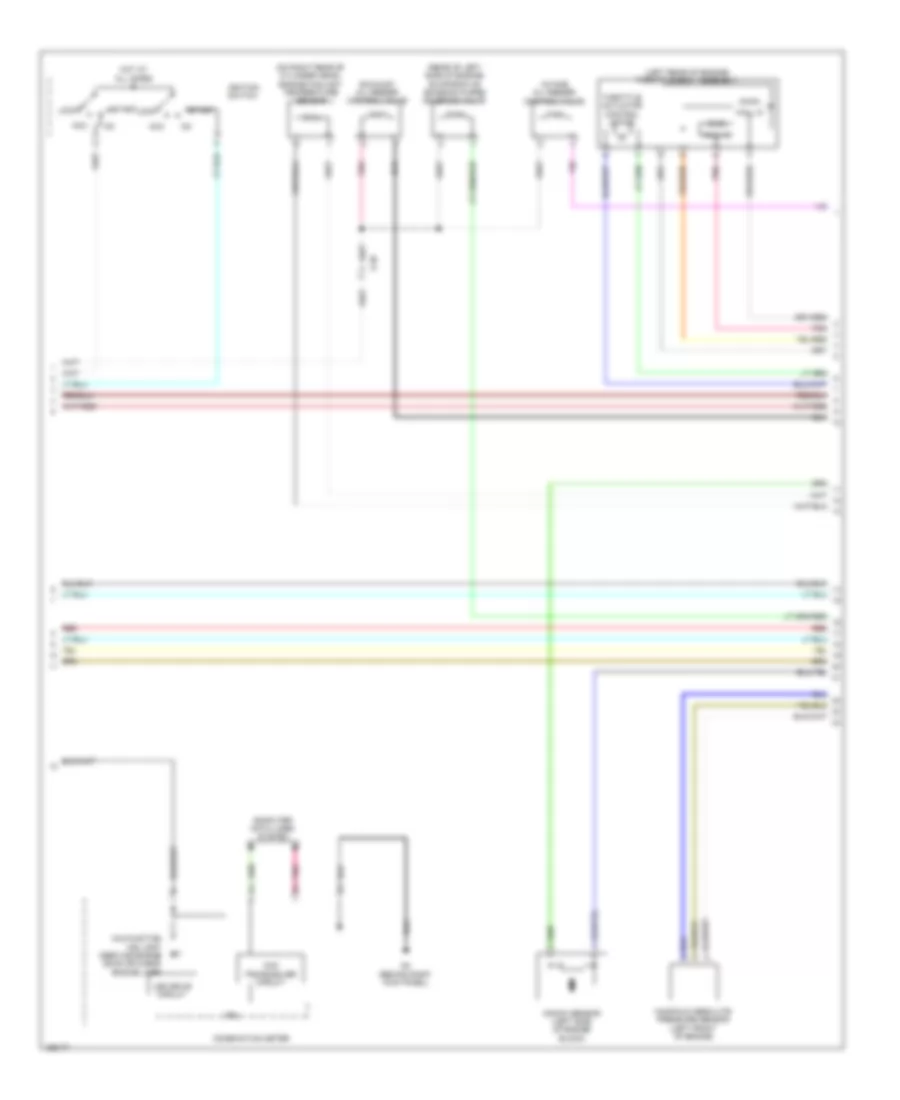
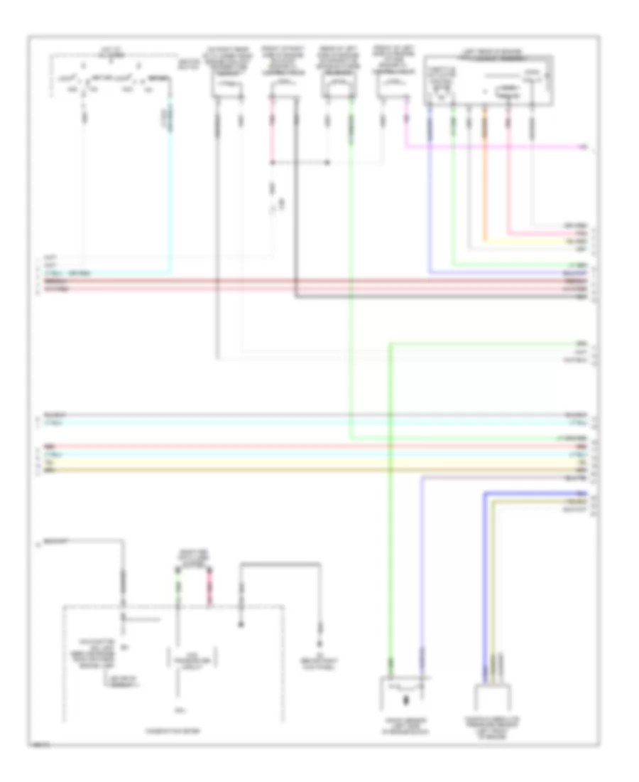
2.0L, Engine Performance Wiring Diagram (1 of 4) for Mitsubishi Lancer ES 2014
List of elements for 2.0L, Engine Performance Wiring Diagram (1 of 4) for Mitsubishi Lancer ES 2014:
- (on underhood fuse/relay block) throttle actuator control motor relay
- A-10
- Air conditioning system
- B-108
- B-109
- C-39
- Computer data lines system
- Cruise control system
- D-14
- Engine compartment relay box (left side of engine compt)
- Engine control module (left rear of engine compt)
- Evaporative emission ventilation solenoid (under left rear of vehicle)
- Exterior lights system
- Fuel tank differential pressure sensor (on top of fuel tank)
- Fuse 10a
- Fuse 15a
- Fuse 20a
- Fuse 7.5a
- Fusible link 36 120a
- Fusible link box (next to battery)
- G16 (rear of engine compt)
- G17 (left front engine compt)
- G18 (left front engine compt)
- Hot at all times
- Mass airflow sensor (on air intake tube)
- Mfi relay
- Pnk
- Red
- Starting/ charging system
- Starting/charging system
- Stop light switch (under left side of dash)
- Vehicle speed sensor (m/t) (on right side of transaxle)
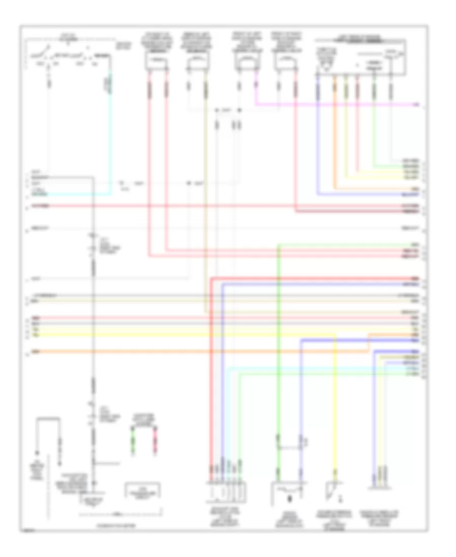
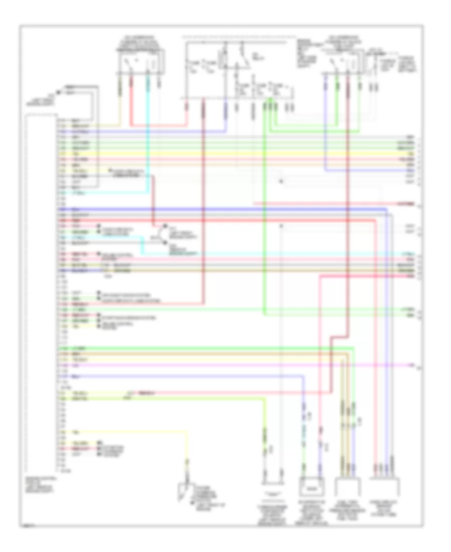
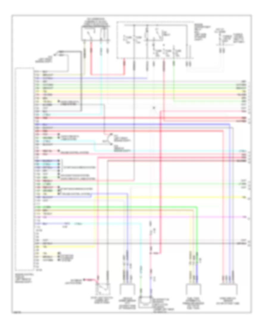
2.0L, Engine Performance Wiring Diagram (2 of 4) for Mitsubishi Lancer ES 2014
List of elements for 2.0L, Engine Performance Wiring Diagram (2 of 4) for Mitsubishi Lancer ES 2014:
- (left "c" pillar) g11
- (main)
- (on underhood fuse/relay block) injector relay
- (sub)
- (top of accelerator pedal assembly) accelerator pedal position sensor
- A-09
- A-10
- C-304
- C-307
- C-312
- C-314
- C-315
- C-317
- C-39
- C-56
- Clutch pedal position switch (m/t)
- Etacs-ecu (on rear of junction block, behind left end of dash)
- Fuel level sensor (main)
- Fuel pump module (top of fuel tank)
- Fuel pump relay
- Fuel tank temperature sensor
- Fuse 15a
- Fuse 7.5a
- G13 (behind left side of dash)
- G18 (left front engine compt)
- G20 (left side of engine compt)
- Hall ic
- Heated oxygen sensor
- Hot at all times
- Ig1 relay
- Instrument cluster system
- Linear air fuel ratio sensor (in exhaust, upstream of catalytic)
- Pnk
- Red
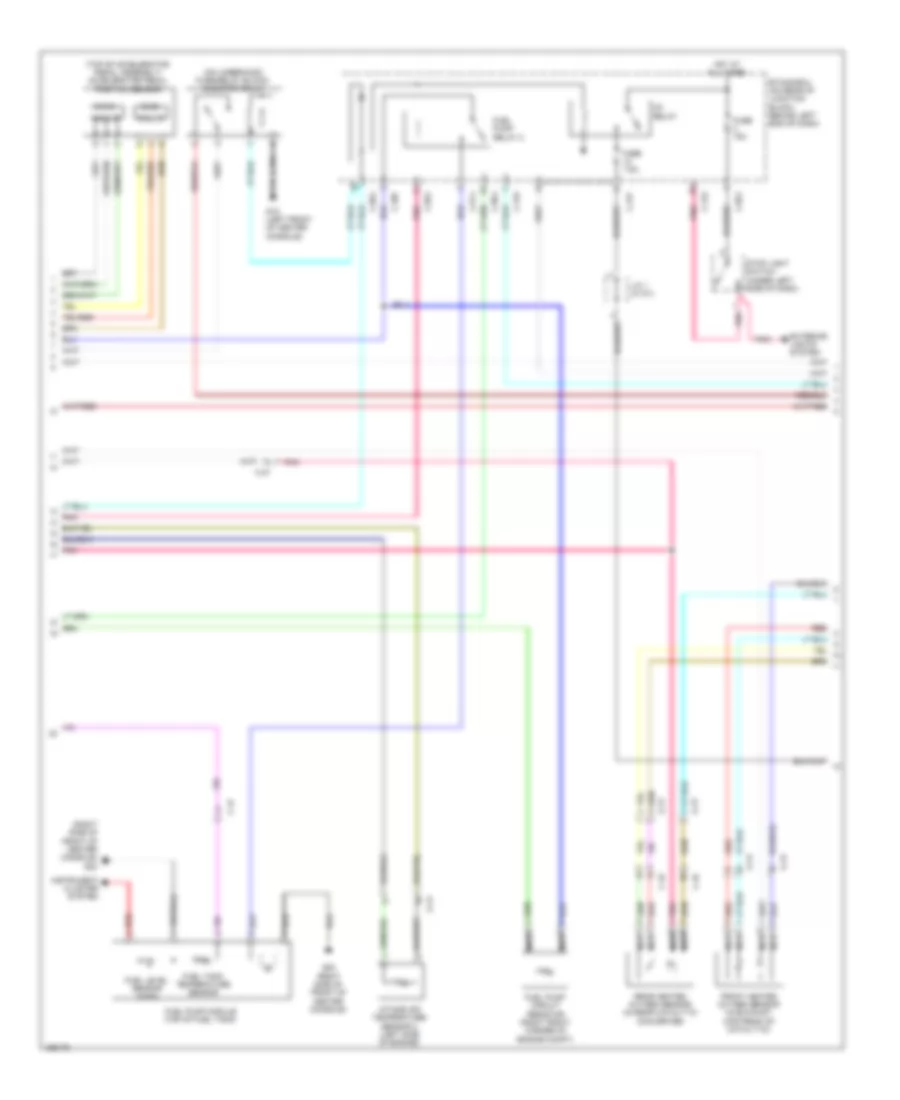
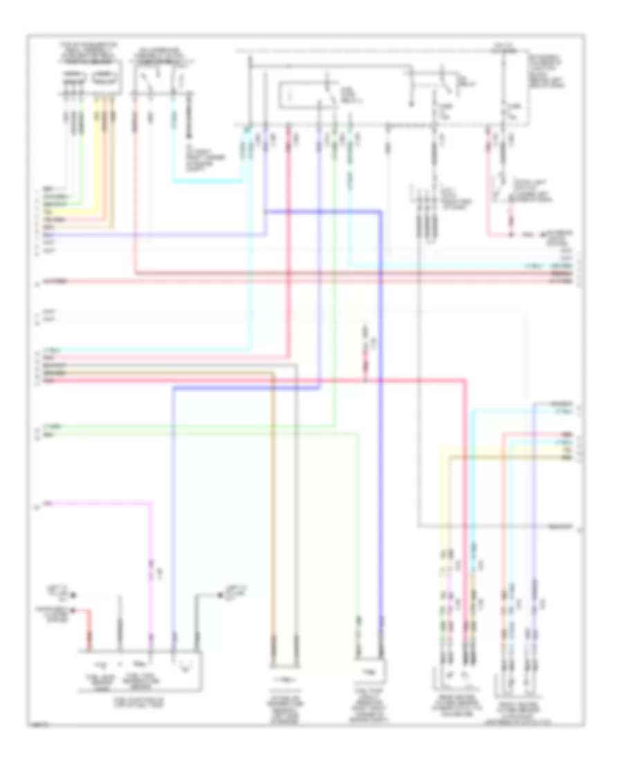
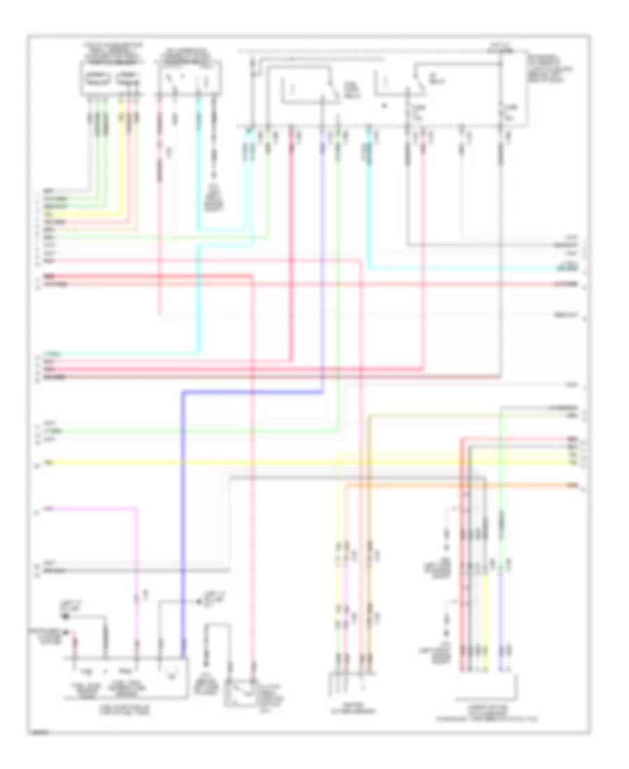
2.0L, Engine Performance Wiring Diagram (3 of 4) for Mitsubishi Lancer ES 2014
List of elements for 2.0L, Engine Performance Wiring Diagram (3 of 4) for Mitsubishi Lancer ES 2014:
- (front of left side of engine) intake engine oil control valve
- (front of right side of engine) exhaust engine oil control valve
- (left rear of engine) throttle body assembly
- (main)
- (on right of cylinder head) engine coolant temperature sensor
- (rear of left side of engine) evaporative emission purge solenoid
- (sub)
- A-10
- Acc
- B-16
- Can transceiver circuit
- Combination meter
- Computer data lines system
- Cpu
- Exhaust gas recirculation valve (left side of engine compt)
- G4 (behind right kick panel)
- Hall ic
- Hot at all times
- Ignition switch
- J/c 1 (c-03) (right end of dash)
- Knock sensor (left side of engine block)
- Led drive circuit
- Lock
- Malfunction ind light (service engine soon or check engine lamp)
- Manifold absolute pressure sensor (left front of engine)
- Pnk
- Power steering pressure switch (2.4l) (left front of engine)
- Red
- Start
- Throttle actuator control motor
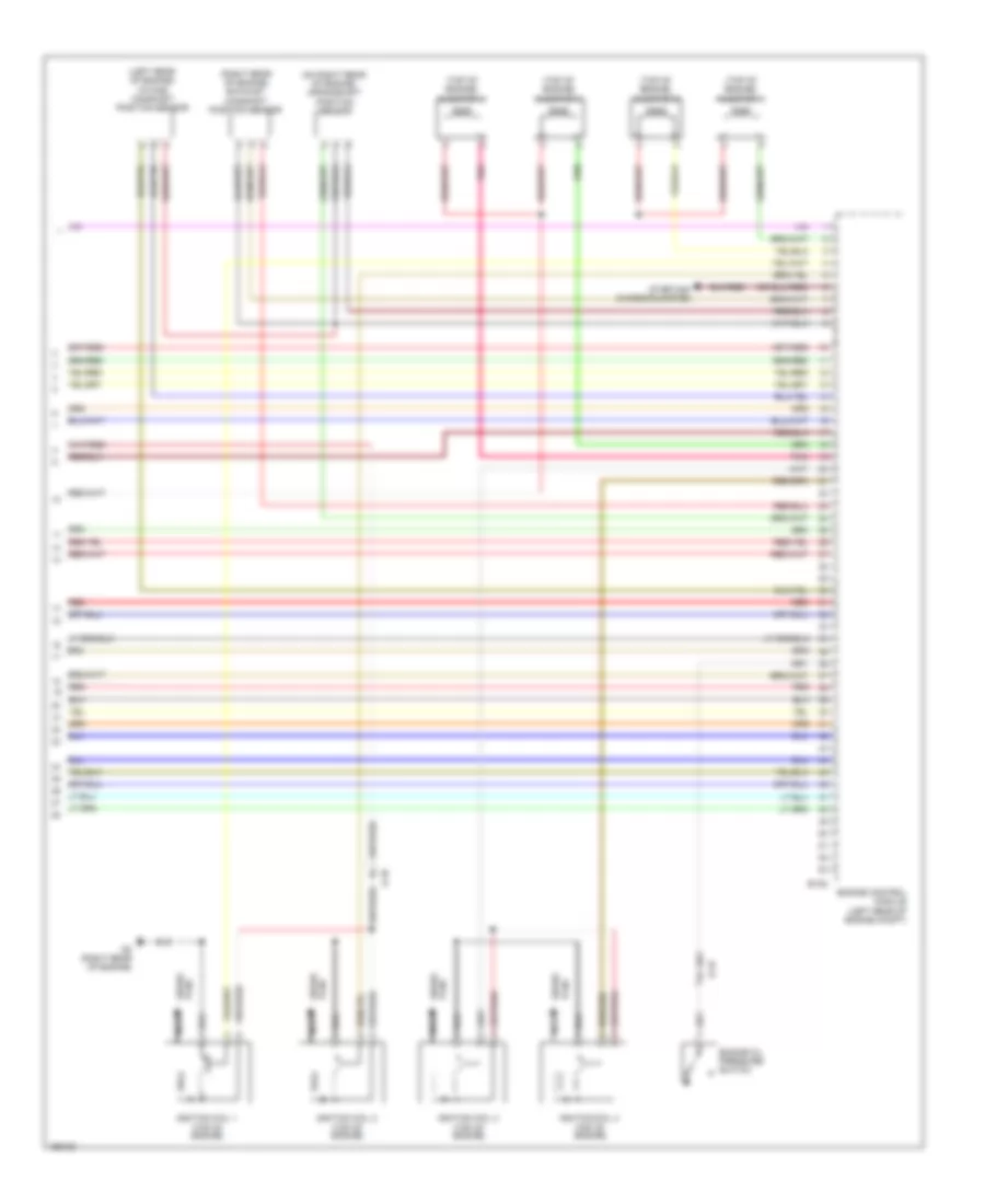
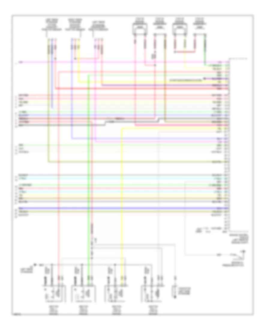
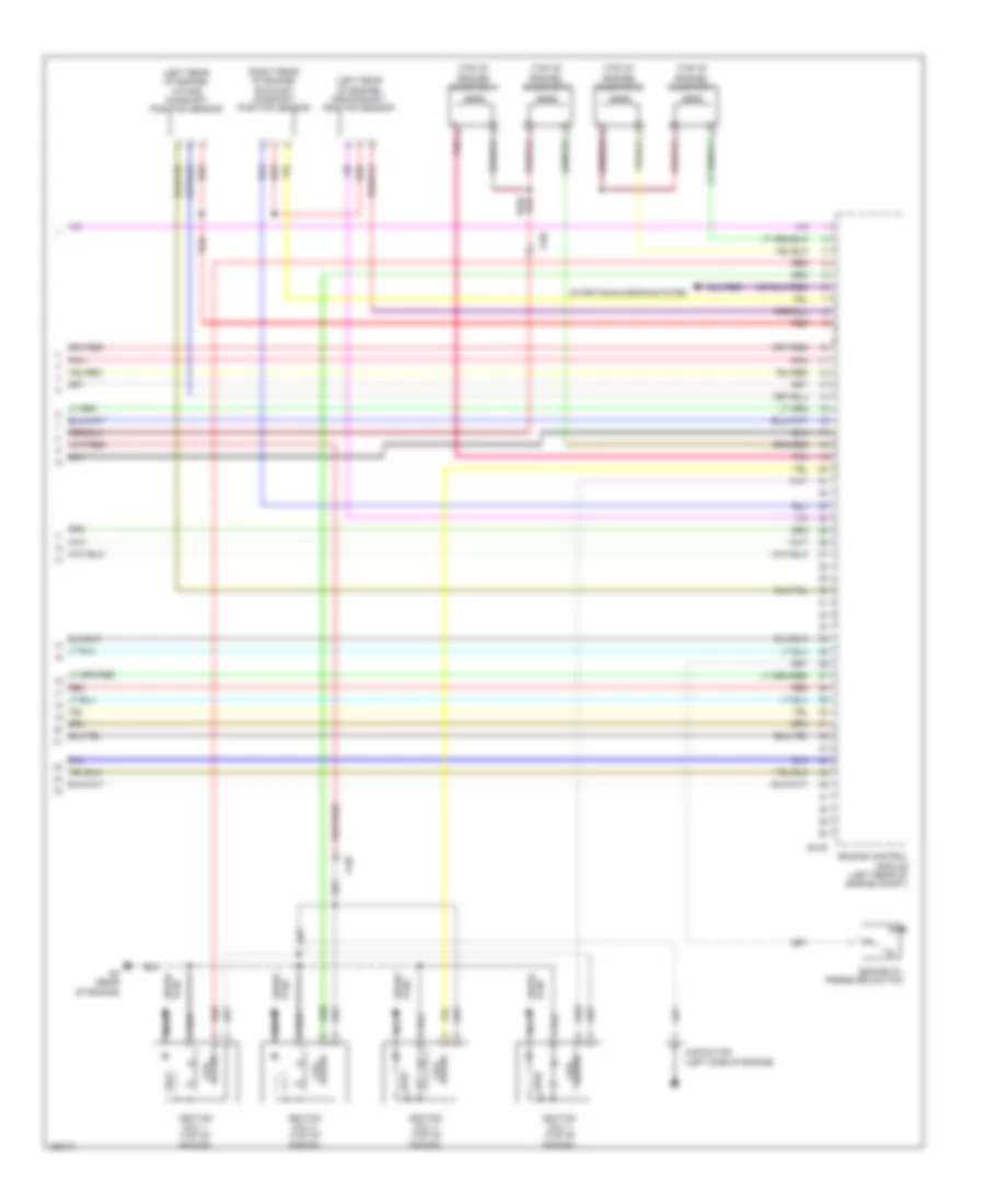
2.0L, Engine Performance Wiring Diagram (4 of 4) for Mitsubishi Lancer ES 2014
List of elements for 2.0L, Engine Performance Wiring Diagram (4 of 4) for Mitsubishi Lancer ES 2014:
- (left rear of engine) intake camshaft position sensor
- (on right rear of engine) crankshaft position sensor
- (right rear of engine) exhaust camshaft position sensor
- (top of engine)
- (top of engine) injector 1
- (top of engine) injector 2
- (top of engine) injector 3
- (top of engine) injector 4
- A-10
- B-108
- B-16
- Engine control module (left rear of engine compt)
- Engine oil pressure switch
- G2 (right rear of engine)
- Ignition coil 1
- Ignition coil 2
- Ignition coil 3
- Ignition coil 4
- Nca
- Plug spark
- Pnk
- Red
- Spark plug
- Starting/ charging system
2.0L TURBO
2.0L Turbo, Engine Performance Wiring Diagram, Evolution (1 of 4) for Mitsubishi Lancer ES 2014
List of elements for 2.0L Turbo, Engine Performance Wiring Diagram, Evolution (1 of 4) for Mitsubishi Lancer ES 2014:
- (behind left kick panel) g14
- (left side engine compt) g19
- (not used)
- (on underhood fuse/relay block) fuel pump relay 1
- (on underhood fuse/relay block) throttle actuator control motor relay
- (rear of engine compt) g16
- 1st & 2nd rail switch (m/t)
- A-13
- Air conditioning system
- B-09
- B-10
- C-47
- Clutch pedal position switch (m/t)
- Computer data lines system
- Cruise control system
- D-17
- Engine compartment relay box (left side of engine compt)
- Engine control module (left rear of engine compt)
- Evaporative emission ventilation solenoid (under left rear of vehicle)
- Fuel tank differential pressure sensor (on top of fuel tank)
- Fuse 10a
- Fuse 15a
- Fuse 20a
- Fuse 7.5a
- Fusible link 36 120a
- Fusible link box (next to battery)
- G15 (left front of center console)
- G5 (behind instrument cluster)
- Hot at all times
- Mass airflow sensor (on air intake tube)
- Mfi relay
- Nca
- Pnk
- Power steering pressure switch (left front of engine)
- Red
- Starting/ charging system
- Starting/charging system
- Turbocharger wastegate solenoid 1
- Turbocharger wastegate solenoid 2
2.0L Turbo, Engine Performance Wiring Diagram, Evolution (2 of 4) for Mitsubishi Lancer ES 2014
List of elements for 2.0L Turbo, Engine Performance Wiring Diagram, Evolution (2 of 4) for Mitsubishi Lancer ES 2014:
- (main)
- (on underhood fuse/relay block) injector relay
- (right side of front of center console) g22
- (sub)
- (top of accelerator pedal assembly) accelerator pedal position sensor
- A-13
- C-304
- C-307
- C-312
- C-314
- C-315
- C-317
- C-45
- C-47
- Etacs-ecu (on rear of junction block, behind left end of dash)
- Exterior lights system
- Front heated oxygen sensor (in exhaust, upstream of catalytic)
- Fuel level sensor (main)
- Fuel pump circuit resistor (right front corner of engine compt)
- Fuel pump module (top of fuel tank)
- Fuel pump relay 2
- Fuel tank temperature sensor
- Fuse 15a
- Fuse 7.5a
- G15 (left front of center console)
- G22 (right side of front of center console)
- Hall ic
- Hot at all times
- Ig1 relay
- Instrument cluster system
- Intake air temperature sensor 2 (left side of engine)
- J/c 1 (c-101)
- Nca
- Pnk
- Rear heated oxygen sensor (in rear catalytic converter)
- Red
- Stop light switch (under left side of dash)
2.0L Turbo, Engine Performance Wiring Diagram, Evolution (3 of 4) for Mitsubishi Lancer ES 2014
List of elements for 2.0L Turbo, Engine Performance Wiring Diagram, Evolution (3 of 4) for Mitsubishi Lancer ES 2014:
- (left rear of engine) throttle body assembly
- (main)
- (on right rear of cylinder head) engine coolant temperature sensor
- (rear of left side of engine) evaporative emission purge solenoid valve
- (sub)
- A-39
- Acc
- Can transceiver circuit
- Combination meter
- Computer data lines system
- Cpu
- Exhaust oil feeder control valve
- G4 (behind right kick panel)
- Hall ic
- Hot at all times
- Ignition switch
- Intake oil feeder control valve
- Knock sensor (left side of engine block)
- Led drive circuit
- Lock
- Malfunction ind light (service engine soon or check engine lamp)
- Manifold absolute pressure sensor (left front of engine)
- Pnk
- Red
- Start
- Throttle actuator control motor
2.0L Turbo, Engine Performance Wiring Diagram, Evolution (4 of 4) for Mitsubishi Lancer ES 2014
List of elements for 2.0L Turbo, Engine Performance Wiring Diagram, Evolution (4 of 4) for Mitsubishi Lancer ES 2014:
- (left rear
- (left rear of engine) intake camshaft position sensor
- (not used)
- (right rear of engine) exhaust camshaft position sensor
- (top of engine) injector 1
- (top of engine) injector 2
- (top of engine) injector 3
- (top of engine) injector 4
- A-13
- A-39
- B-09
- Capacitor (left side of engine)
- Driver coil
- Engine control module (left rear of engine compt)
- Engine oil pressure switch
- G3 (left rear of engine)
- Ignition coil 1 (top of engine)
- Ignition coil 2 (top of engine)
- Ignition coil 3 (top of engine)
- Ignition coil 4 (top of engine)
- Nca
- Of engine) crankshaft position sensor
- Plug spark
- Pnk
- Red
- Spark plug
- Starting/charging system
2.0L Turbo, Engine Performance Wiring Diagram, Except Evolution (1 of 4) for Mitsubishi Lancer ES 2014
List of elements for 2.0L Turbo, Engine Performance Wiring Diagram, Except Evolution (1 of 4) for Mitsubishi Lancer ES 2014:
- (on underhood fuse/relay block) fuel pump relay 1
- (on underhood fuse/relay block) throttle actuator control motor relay
- A-54
- Air conditioning system
- B-108
- B-109
- C-39
- Computer data lines system
- Cruise control system
- D-14
- Engine compartment relay box (left side of engine compt)
- Engine control module (left rear of engine compt)
- Evaporative emission ventilation solenoid (under left rear of vehicle)
- Fuel tank differential pressure sensor (on top of fuel tank)
- Fuse 10a
- Fuse 15a
- Fuse 20a
- Fuse 7.5a
- Fusible link 36 120a
- Fusible link box (next to battery)
- G16 (rear of engine compt)
- G17 (left front engine compt)
- G18 (left front engine compt)
- Hot at all times
- Mass airflow sensor (on air intake tube)
- Mfi relay
- Nca
- Pnk
- Power steering pressure switch (left front of engine)
- Red
- Starting/ charging system
- Starting/charging system
- Turbocharger wastegate solenoid (left rear of engine compt)
2.0L Turbo, Engine Performance Wiring Diagram, Except Evolution (2 of 4) for Mitsubishi Lancer ES 2014
List of elements for 2.0L Turbo, Engine Performance Wiring Diagram, Except Evolution (2 of 4) for Mitsubishi Lancer ES 2014:
- (left "c" pillar) g11
- (main)
- (on underhood fuse/relay block) injector relay
- (sub)
- (top of accelerator pedal assembly) accelerator pedal position sensor
- A-54
- C-304
- C-307
- C-312
- C-314
- C-315
- C-317
- C-39
- C-56
- Etacs-ecu (on rear of junction block, behind left end of dash)
- Exterior lights system
- Front heated oxygen sensor (in exhaust, upstream of catalytic)
- Fuel level sensor (main)
- Fuel pump circuit resistor (right front corner of engine compt)
- Fuel pump module (top of fuel tank)
- Fuel pump relay 2
- Fuel tank temperature sensor
- Fuse 15a
- Fuse 7.5a
- G1 (at right front corner of engine compt)
- Hall ic
- Hot at all times
- Ig1 relay
- Instrument cluster system
- Intake air temperature sensor 2 (left side of engine)
- J/c 1 (c-03) (right end of dash)
- Nca
- Pnk
- Rear heated oxygen sensor (in rear catalytic converter)
- Red
- Stop light switch (under left side of dash)
2.0L Turbo, Engine Performance Wiring Diagram, Except Evolution (3 of 4) for Mitsubishi Lancer ES 2014
List of elements for 2.0L Turbo, Engine Performance Wiring Diagram, Except Evolution (3 of 4) for Mitsubishi Lancer ES 2014:
- (front of left side of engine) intake engine oil control valve
- (front of right side of engine) exhaust engine oil control valve
- (left rear of engine) throttle body assembly
- (main)
- (on right rear of cylinder head) engine coolant temperature sensor
- (rear of left side of engine) evaporative emission purge solenoid
- (sub)
- A-60
- Acc
- Can transceiver circuit
- Combination meter
- Computer data lines system
- Cpu
- G4 (behind right kick panel)
- Hall ic
- Hot at all times
- Ignition switch
- Knock sensor (left side of engine block)
- Led drive circuit
- Lock
- Malfunction ind light (service engine soon or check engine lamp)
- Manifold absolute pressure sensor (left front of engine)
- Pnk
- Red
- Start
- Throttle actuator control motor
2.0L Turbo, Engine Performance Wiring Diagram, Except Evolution (4 of 4) for Mitsubishi Lancer ES 2014
List of elements for 2.0L Turbo, Engine Performance Wiring Diagram, Except Evolution (4 of 4) for Mitsubishi Lancer ES 2014:
- (left rear of engine) crankshaft position sensor
- (left rear of engine) intake camshaft position sensor
- (right rear of engine) exhaust camshaft position sensor
- (top of engine) injector 1
- (top of engine) injector 2
- (top of engine) injector 3
- (top of engine) injector 4
- A-60
- B-108
- Capacitor (left side of engine)
- Coil driver
- Engine control module (left rear of engine compt)
- Engine oil pressure switch
- G2 (rear of engine)
- Ignition coil 1 (top of engine)
- Ignition coil 2 (top of engine)
- Ignition coil 3 (top of engine)
- Ignition coil 4 (top of engine)
- Nca
- Plug spark
- Pnk
- Red
- Spark plug
- Starting/charging system
2.4L
2.4L, Engine Performance Wiring Diagram (1 of 4) for Mitsubishi Lancer ES 2014
List of elements for 2.4L, Engine Performance Wiring Diagram (1 of 4) for Mitsubishi Lancer ES 2014:
- (on underhood fuse/relay block) throttle actuator control motor relay
- A-10
- Air conditioning system
- B-108
- B-109
- C-39
- Computer data lines system
- Cruise control system
- D-14
- Engine compartment relay box (left side of engine compt)
- Engine control module (left rear of engine compt)
- Evaporative emission ventilation solenoid (under left rear of vehicle)
- Exterior lights system
- Fuel tank differential pressure sensor (on top of fuel tank)
- Fuse 10a
- Fuse 15a
- Fuse 20a
- Fuse 7.5a
- Fusible link 36 120a
- Fusible link box (next to battery)
- G16 (rear of engine compt)
- G17 (left front engine compt)
- G18 (left front engine compt)
- Hot at all times
- Mass airflow sensor (on air intake tube)
- Mfi relay
- Pnk
- Red
- Starting/ charging system
- Starting/charging system
- Stop light switch (under left side of dash)
- Vehicle speed sensor (m/t) (on right side of transaxle)
2.4L, Engine Performance Wiring Diagram (2 of 4) for Mitsubishi Lancer ES 2014
List of elements for 2.4L, Engine Performance Wiring Diagram (2 of 4) for Mitsubishi Lancer ES 2014:
- (left "c" pillar) g11
- (main)
- (on underhood fuse/relay block) injector relay
- (sub)
- (top of accelerator pedal assembly) accelerator pedal position sensor
- A-09
- A-10
- C-304
- C-307
- C-312
- C-314
- C-315
- C-317
- C-39
- C-56
- Clutch pedal position switch (m/t)
- Etacs-ecu (on rear of junction block, behind left end of dash)
- Fuel level sensor (main)
- Fuel pump module (top of fuel tank)
- Fuel pump relay
- Fuel tank temperature sensor
- Fuse 15a
- Fuse 7.5a
- G13 (behind left side of dash)
- G18 (left front engine compt)
- G20 (left side of engine compt)
- Hall ic
- Heated oxygen sensor
- Hot at all times
- Ig1 relay
- Instrument cluster system
- Linear air fuel ratio sensor (in exhaust, upstream of catalytic)
- Pnk
- Red
2.4L, Engine Performance Wiring Diagram (3 of 4) for Mitsubishi Lancer ES 2014
List of elements for 2.4L, Engine Performance Wiring Diagram (3 of 4) for Mitsubishi Lancer ES 2014:
- (front of left side of engine) intake engine oil control valve
- (front of right side of engine) exhaust engine oil control valve
- (left rear of engine) throttle body assembly
- (main)
- (on right of cylinder head) engine coolant temperature sensor
- (rear of left side of engine) evaporative emission purge solenoid
- (sub)
- A-10
- Acc
- B-16
- Can transceiver circuit
- Combination meter
- Computer data lines system
- Cpu
- Exhaust gas recirculation valve (left side of engine compt)
- G4 (behind right kick panel)
- Hall ic
- Hot at all times
- Ignition switch
- J/c 1 (c-03) (right end of dash)
- Knock sensor (left side of engine block)
- Led drive circuit
- Lock
- Malfunction ind light (service engine soon or check engine lamp)
- Manifold absolute pressure sensor (left front of engine)
- Pnk
- Power steering pressure switch (2.4l) (left front of engine)
- Red
- Start
- Throttle actuator control motor
2.4L, Engine Performance Wiring Diagram (4 of 4) for Mitsubishi Lancer ES 2014
List of elements for 2.4L, Engine Performance Wiring Diagram (4 of 4) for Mitsubishi Lancer ES 2014:
- (left rear of engine) intake camshaft position sensor
- (on right rear of engine) crankshaft position sensor
- (right rear of engine) exhaust camshaft position sensor
- (top of engine)
- (top of engine) injector 1
- (top of engine) injector 2
- (top of engine) injector 3
- (top of engine) injector 4
- A-10
- B-108
- B-16
- Engine control module (left rear of engine compt)
- Engine oil pressure switch
- G2 (right rear of engine)
- Ignition coil 1
- Ignition coil 2
- Ignition coil 3
- Ignition coil 4
- Nca
- Plug spark
- Pnk
- Red
- Spark plug
- Starting/ charging system
EXTERIOR LIGHTS
Backup Lamps Wiring Diagram, Evolution for Mitsubishi Lancer ES 2014
List of elements for Backup Lamps Wiring Diagram, Evolution for Mitsubishi Lancer ES 2014:
- A-13
- Backup light switch
- C-133
- C-144
- C-27
- C-304
- C-311
- C-313
- C-42
- C-47
- Cpu
- D-17
- Etacs-ecu (on rear of junction block, behind left end of dash)
- F-27
- Fuse 7.5a
- G11 (left side of luggage compt)
- High side switch (r)
- Hot w/ ig1 relay energized
- Inside rearview mirror assembly
- J/c 4 (c-43)
- Left backup light
- Lever position sensor (r)
- M/t
- Multi-vision display
- Nca
- Right backup light
- Shift lever (center console)
- Tc-sst
Backup Lamps Wiring Diagram, Except Evolution for Mitsubishi Lancer ES 2014
List of elements for Backup Lamps Wiring Diagram, Except Evolution for Mitsubishi Lancer ES 2014:
- (on liftgate) g21
- A-10
- Backup light switch
- C-130
- C-151
- C-153
- C-304
- C-311
- C-313
- C-36
- C-39
- C-40
- C-49
- Cpu
- Cvt
- D-14
- Etacs-ecu (on rear of junction block, behind left end of dash)
- Except turbo
- F-23
- F-30
- Fuse 7.5a
- G10 (at left "c" pillar)
- Hatchback
- High side switch (r)
- Hot w/ ig1 relay energized
- Inside rearview mirror assembly
- Left backup light
- Lever position sensor (r)
- M/t
- Multi-vision display
- Nca
- Radio & cd player
- Right backup light
- Sedan
- Shift lever (center console)
- Spare connector (w/ navigation unit)
- Transaxle control module (behind left end of dash)
- Transmission range switch (top of p transmission)
- Turbo
Exterior Lamps Wiring Diagram, Evolution (1 of 2) for Mitsubishi Lancer ES 2014
List of elements for Exterior Lamps Wiring Diagram, Evolution (1 of 2) for Mitsubishi Lancer ES 2014:
- C-130
- C-301
- C-304
- C-311
- C-312
- C-35
- C-47
- D-11
- D-16
- D-17
- Etacs-ecu (on rear of junction block, behind left end of dash)
- F-27
- Fuse 10 15a
- Fuse 2 15a
- G11 (left "c" pillar)
- G11 (left side of luggage compt)
- G5 (behind instrument cluster)
- G9 (at right "c" pillar)
- High-mounted stoplight
- Hot at all times
- J/c 4 (c-43)
- Left headlight assembly
- Left license plate light
- Left rear combination light
- Left rear side marker light
- Left side turn signal light
- Nca
- Pnk
- Red
- Right headlight assembly
- Right license plate light
- Right rear combination light
- Right rear side marker light
- Right side turn signal light
- Shift lever (center console)
- Stop
- Stoplight switch (under left side of dash)
- Tail
- Taillight control circuit
- Turn
- Turn signal light control circuit
Exterior Lamps Wiring Diagram, Evolution (2 of 2) for Mitsubishi Lancer ES 2014
List of elements for Exterior Lamps Wiring Diagram, Evolution (2 of 2) for Mitsubishi Lancer ES 2014:
- Anti-theft system
- Auto (w/ automatic light)
- C-133
- C-301
- C-316
- C-317
- Can drive circuit
- Can transceiver circuit
- Center panel unit
- Column ecu
- Column switch-ecu (on top of steering column)
- Combination meter
- Computer data lines system
- Cpu
- Etacs-ecu (on rear of junction block, behind left end of dash)
- Fuse 12 7.5a
- Fuse 8 7.5a
- G4 (behind right kick panel)
- G6 (behind center of dash)
- Hazard warning switch
- Head
- Hot at all times
- Hot w/ ig1 relay energized
- Interface circuit
- Interior lights system
- J/c 1 (c-101)
- Led drive circuit
- Left
- Left turn ind
- Lighting control sensor (w/ automatic light) (center top of windshield)
- Lighting switch
- Lin drive circuit
- Pnk
- Power tops system
- Right
- Right turn ind
- Tail
- Tail ind
- Turn signal light switch
Exterior Lamps Wiring Diagram, Except Evolution (1 of 2) for Mitsubishi Lancer ES 2014
List of elements for Exterior Lamps Wiring Diagram, Except Evolution (1 of 2) for Mitsubishi Lancer ES 2014:
- C-127
- C-301
- C-304
- C-311
- C-312
- C-39
- C-54
- D-11
- D-14
- D-15
- D-23
- Etacs-ecu (on rear of junction block, behind left end of dash)
- Except turbo
- F-15
- F-23
- Fuse 10 15a
- Fuse 2 15a
- G10 (at left "c" pillar)
- G13 (behind left side of dash)
- G16 (rear of engine compt)
- G9 (at right "c" pillar)
- High-mounted stoplight
- Hot at all times
- Left headlight assembly
- Left license plate light
- Left rear combination light
- Left side turn signal light
- Left taillight
- Nca
- Pnk
- Red
- Right headlight assembly
- Right license plate light
- Right rear combination light
- Right side turn signal light
- Right taillight
- Shift lever (center console)
- Stop
- Stop light switch (under left side of dash)
- Taillight control circuit
- Turbo
- Turn
- Turn signal light control circuit
Exterior Lamps Wiring Diagram, Except Evolution (2 of 2) for Mitsubishi Lancer ES 2014
List of elements for Exterior Lamps Wiring Diagram, Except Evolution (2 of 2) for Mitsubishi Lancer ES 2014:
- Anti-theft system
- Auto (w/ automatic light)
- C-130
- C-301
- C-316
- C-317
- Can drive circuit
- Can transceiver circuit
- Center panel unit
- Column ecu
- Column switch-ecu (on top of steering column)
- Combination meter
- Computer data lines system
- Cpu
- Etacs-ecu (on rear of junction block, behind left end of dash)
- Fuse 12 7.5a
- Fuse 8 7.5a
- G4 (behind right kick panel)
- G7 (top left side of headliner)
- Hazard warning switch
- Head
- Hot at all times
- Hot w/ ig1 relay energized
- Interface circuit
- Interior lights system
- J/c 1 (c-03) (right end of dash)
- Led drive circuit
- Left
- Left turn ind
- Lighting control sensor (w/ automatic light) (center top of windshield)
- Lighting switch
- Lin drive circuit
- Pnk
- Power tops system
- Right
- Right turn ind
- Tail
- Tail ind
- Turn signal light switch
Exterior Lamps Wiring Diagram, Hatchback (1 of 2) for Mitsubishi Lancer ES 2014
List of elements for Exterior Lamps Wiring Diagram, Hatchback (1 of 2) for Mitsubishi Lancer ES 2014:
- (not used)
- C-301
- C-304
- C-311
- C-312
- C-39
- D-11
- D-14
- D-15
- Etacs-ecu (on rear of junction block, behind left end of dash)
- F-30
- Fuse 10 15a
- Fuse 2 15a
- G10 (at left "c" pillar)
- G13 (behind left side of dash)
- G21
- G9 (at right "c" pillar)
- High-mounted stoplight
- Hot at all times
- Left headlight assembly
- Left license plate light
- Left rear combination light
- Left rear side marker light
- Left rear turn signal lamp
- Left side turn signal light
- Nca
- Pnk
- Red
- Right headlight assembly
- Right license plate light
- Right rear combination light
- Right rear side marker light
- Right rear turn signal lamp
- Right side turn signal light
- Stop
- Stoplight switch (under left side of dash)
- Tail
- Taillight control circuit
- Turn signal light control circuit
Exterior Lamps Wiring Diagram, Hatchback (2 of 2) for Mitsubishi Lancer ES 2014
List of elements for Exterior Lamps Wiring Diagram, Hatchback (2 of 2) for Mitsubishi Lancer ES 2014:
- Anti-theft system
- Auto (w/ automatic light)
- C-130
- C-301
- C-316
- C-317
- Can drive circuit
- Can transceiver circuit
- Center panel unit
- Column ecu
- Column switch-ecu (on top of steering column)
- Combination meter
- Computer data lines system
- Cpu
- Etacs-ecu (on rear of junction block, behind left end of dash)
- Fuse 12 7.5a
- Fuse 8 7.5a
- G4 (behind right kick panel)
- G7 (top left side of headliner)
- Hazard warning switch
- Head
- Hot at all times
- Hot w/ ig1 relay energized
- Interface circuit
- Interior lights system
- J/c 1 (c-03) (right side of dash)
- Led drive circuit
- Left
- Left turn ind
- Lighting control sensor (w/ automatic light) (center top of windshield)
- Lighting switch
- Lin drive circuit
- Pnk
- Power tops system
- Right
- Right turn ind
- Tail
- Tail ind
- Turn signal light switch
GROUND DISTRIBUTION
Ground Distribution Wiring Diagram, Evolution (1 of 2) for Mitsubishi Lancer ES 2014
List of elements for Ground Distribution Wiring Diagram, Evolution (1 of 2) for Mitsubishi Lancer ES 2014:
- 1st & 2nd rail switch
- Engine control module
- G1 (at right front corner of engine compt)
- G11 (left "c" pillar)
- G12 (under left side of driver's seat)
- G14 (behind left kick panel)
- G15 (left front of center console)
- G18 (left front engine compt)
- G3 (2.0l & 2.4l: rear of engine) (2.0l turbo: left rear of engine)
- G6 (behind center of dash)
- G9 (at right "c" pillar)
- Hood switch, windshield wiper motor, starter relay, left headlight assembly (w/ hid), electric pump relay brake fluid level switch, engine control module, left fog light, right fog light & injector relay
- Ignition coil 1, ignition coil 2, ignition coil 3 & ignition coil 4
- Inside rearview mirror assembly, sunroof motor assembly, front dome light & lighting control sensor (w/ automatic light)
- Left rear side marker light, right rear side marker light, left turn rear combination light, rear combination light (left taillight), rear combination light (left stoplight), trunk lid opener switch, high mounted stoplight, right license plate light, left license plate light, left backup light, right backup light & trunk lid latch
- Rear window defogger
- Remote controlled mirror switch, left door mirror assembly, shift lever, power window main switch, etacs ecu, meter information switch, left front door lock/unlock switch, heated seat switch, heated seat relay, left front door lock actuator, accessory socket, data link connector, asc off switch & combination meter
- Right headlight assembly (w/ hid)
- Right turn rear combination light, electric pump, proportioning valve (ayc control), proportioning valve (acd control), left direction valve, right direction valve, rear combination light (right stoplight) & rear combination light (right taillight)
- Steering wheel audio remote control switch & steering wheel voice control switch
- Steering wheel sensor
- Transaxle assembly
Ground Distribution Wiring Diagram, Evolution (2 of 2) for Mitsubishi Lancer ES 2014
List of elements for Ground Distribution Wiring Diagram, Evolution (2 of 2) for Mitsubishi Lancer ES 2014:
- (automatic a/c),
- A/c control panel
- Asc-ecu
- Awc-ecu
- Battery
- Data link connector combination meter & power transistor
- Driver's side seat belt switch, audio amplifier, left heated seat assembly, right heated seat assembly & audio amplifier
- Engine control module
- Engine control module, condenser fan motor & fan control relay
- Fuel pump module
- G13 (behind left side of dash)
- G16 (rear of engine compt)
- G17 (left front engine compt)
- G19 (left side of engine compt)
- G2 (2.0l & 2.4l: right rear of engine) (2.0l turbo: rear of engine)
- G20 (left side of engine compt)
- G21 (on liftgate)
- G22 (right side of front of center console)
- G4 (behind right kick panel)
- G5 (behind instrument cluster)
- G7 (top left side of headliner)
- Hood switch, headlight assembly (left position light), headlight assembly (right position light), headlight assembly (left turn), headlight assembly (right turn), shift lever, left side turn signal light, right side turn signal light, stoplight switch, clutch pedal position switch (m/t), left drl headlight assembly (w/ hid), right drl headlight assembly (w/ hid), left headlight assembly (w/o hid) & right headlight assembly (w/o hid)
- J/c 5 (d-27)
- Kos-ecu, (w/ keyless operation key) radio & cd player, center panel unit, satellite radio tuner (if equipped), right front door lock actuator & front power window sub switch
- Left heated seat assembly, right heated seat assembly & driver side seat belt switch
- Right door mirror assembly, heater control panel, paddle shift switch, multivision display, right front door lock/unlock switch, hands free module, column switch, wireless control module (w/o keyless entry), key reminder switch,
- Srs ecu
Ground Distribution Wiring Diagram, Except Evolution for Mitsubishi Lancer ES 2014
List of elements for Ground Distribution Wiring Diagram, Except Evolution for Mitsubishi Lancer ES 2014:
- (hatchback)
- (hatchback),
- (m/t), (w/ drl), (w/ drl),
- (w/ halogen type),
- 2.0l & 2.4l
- 2.0l turbo
- Audio amplifier, driver's side seat belt switch, left heated seat assembly & right heated seat assembly
- Awc-ecu
- Battery
- Clock spring, steering wheel audio remote control switch, steering wheel voice control switch & cruise control switch
- Combination meter & srs-ecu
- Control module, asc-ecu & abs-ecu
- Data link connector
- Driver side seat belt switch, left heated seat assembly & right heated seat assembly
- Electric power steering ecu (2.0l)
- Engine control module
- Fuel pump module
- G1 (at right front corner of engine compt)
- G10 (at left "c" pillar)
- G11 (left "c" pillar)
- G12 (under left side of driver's seat)
- G13 (behind left side of dash)
- G14 (behind left kick panel)
- G15 (left front of center console)
- G16 (rear of engine compt)
- G17 (left front engine compt)
- G18 (left front engine compt)
- G19 (left side engine compt)
- G2 (2.0l & 2.4l: right rear of engine) (2.0l turbo: rear of engine)
- G20 (left side of engine compt)
- G21 (on liftgate)
- G22 (right side of front of center console)
- G3 (2.0l & 2.4l: rear of engine) (2.0l turbo: left rear of engine)
- G4 (behind right kick panel)
- G5 (behind instrument cluster)
- G6 (behind center of dash)
- G7 (top left side of headliner)
- G9 (at right "c" pillar)
- Hatchback
- Headlight assembly (left turn signal light), headlight assembly (right turn signal light), right side turn signal light, stop light switch, clutch pedal position switch left headlight assembly right headlight assembly left side turn signal light & shift lever
- Heated seat switch, asc off switch, combination meter, accessory socket (rear floor console), accessory socket (front floor console), cigarette lighter (front floor console), data link connector, drive mode selector, left front door lock actuator, left front door lock switch, headlight leveling switch, left door mirror assembly, heated seat relay, left front door lock/unlock switch, meter information switch, etacs-ecu, power window main switch, remote controlled mirror switch, shift switch assembly & shift lever
- High mounted stop light, rear wiper motor, liftgate lock actuator liftgate lock release handle & liftgate switch
- Injector relay engine control module, condenser fan motor & fan control relay
- J/c 2 (d-52) (base of left "b" pillar)
- Left headlight assembly (w/ discharge type), electric pump relay, brake fluid level switch, left fog light, right fog light, cvt control relay, injector relay, starter relay & windshield wiper motor
- Left headlight assembly right headlight assembly
- Left rear turn-signal light right backup light, left backup light, high-mounted stop light, left license plate light, right license plate light, right taillight & left taillight
- Lighting control sensor (w/ automatic light), inside rearview mirror assembly, front dome light & sunroof motor assembly
- Linear air fuel radio sensor shield & engine control module
- Linear air fuel radio sensor shield ignition coil 1, ignition coil 2, ignition coil 3 & ignition coil 4
- Rear window defogger
- Right front seat assembly
- Right headlight assembly (w/ discharge type)
- Right rear turn signal light luggage compartment light (hatchback), electric pump, proportioning valve, right rear combination light & right rear combination taillight/side marker light
- Spare connector (for handsfree module) spare connector (for navigation unit), a/c ecu, power transistor, satellite radio tuner, multivision display, radio & cd player, key reminder switch, right front door lock actuator, front power window sub switch, wireless control module (w/o keyless entry), kos-ecu (if equipped), column switch, hands free module, spare connector (for satellite radio turner) heater control panel (manual a/c), a/c control panel (automatic a/c), right door mirror assembly, right front door lock/unlock switch & paddle shift switch
- Steering wheel sensor
- Transaxle
- Transaxle assembly
- Trunk lid opener, left rear combination light, trunk lid lock actuator & left rear combination taillight/side marker light
HEADLIGHTS
Headlights Wiring Diagram, with High Intensity Discharge (1 of 2) for Mitsubishi Lancer ES 2014
List of elements for Headlights Wiring Diagram, with High Intensity Discharge (1 of 2) for Mitsubishi Lancer ES 2014:
- (behind instrument cluster) (evolution) g5
- A-39
- A-50
- Anti-theft system
- Beam ind
- C-130
- C-133
- C-22
- C-23
- C-301
- C-304
- C-312
- C-316
- C-317
- Can drive circuit
- Can transceiver circuit
- Circuit
- Circuit headlight backup
- Circuit lin drive
- Combination meter
- Computer data lines system
- Cpu
- Daytime running light relay (on underhood fuse/relay block)
- Engine compartment relay box (left side of engine compt)
- Etacs-ecu (on rear of junction block, behind left end of dash)
- Evolution
- Except evolution
- Exterior lights system
- Fog ind
- Fog light relay
- Fuse 10a
- Fuse 15a
- Fuse 7.5a
- G1 (at right front corner of engine compt)
- G13 (except evolution) (behind left side of dash)
- G4 (behind right kick panel)
- G7 (except evolution) (top left side of headliner)
- G8 (evolution)
- Hot at all times
- Hot w/ ig1 relay energized
- Ignition control
- Interface circuit
- J/c 1 (c-03) (except evolution) j/c 1 (c-101) (evolution) (except evolution: right side of dash)
- Led drive circuit
- Left drl headlight assembly
- Left fog light
- Lighting control sensor (w/ automatic light) (center top of windshield)
- Nca
- Parking brake switch
- Pnk
- Red
- Right drl headlight assembly
- Right fog light
- Taillight control
Headlights Wiring Diagram, with High Intensity Discharge (2 of 2) for Mitsubishi Lancer ES 2014
List of elements for Headlights Wiring Diagram, with High Intensity Discharge (2 of 2) for Mitsubishi Lancer ES 2014:
- Auto switch (w/ automatic light)
- Column switch-ecu (on top of steering column)
- Column-ecu
- Dimmer switch
- Engine compartment relay box (left side of engine compt)
- Evolution
- Except evolution
- Fog lighting switch
- Fuse 10a
- Fuse 20a
- Fusible link 36 120a
- Fusible link box (next to battery)
- G1 (at right front corner of engine compt)
- G4 (behind right kick panel)
- Head lighting switch
- Headlight control unit
- Headlight relay (high)
- Headlight relay (low)
- Hot at all times
- Left fog light
- Left headlight assembly
- Nca
- Off
- Pass
- Passing switch
- Right fog light
- Right headlight assembly
- Solenoid
- Tail lighting switch
Headlights Wiring Diagram, without High Intensity Discharge (1 of 2) for Mitsubishi Lancer ES 2014
List of elements for Headlights Wiring Diagram, without High Intensity Discharge (1 of 2) for Mitsubishi Lancer ES 2014:
- (not used)
- A-50
- Anti-theft system
- Beam ind
- C-128
- C-130 (except evolution)
- C-131
- C-133 (evolution)
- C-134
- C-19
- C-22
- C-23
- C-301
- C-304
- C-312
- C-316
- C-317
- Can transceiver circuit
- Circuit
- Circuit can drive
- Circuit headlight backup
- Circuit interface
- Combination meter
- Computer data lines system
- Cpu
- Engine compartment relay box (left side of engine compt)
- Etacs-ecu (on rear of junction block, behind left end of dash)
- Evolution
- Except evolution
- Exterior lights system
- Field effect transistor
- Fog ind
- Fog light relay
- Fuse 1 15a
- Fuse 10a
- Fuse 7.5a
- Fusible link 36 120a
- Fusible link box (next to battery)
- G4 (behind right kick panel)
- G7 (except evolution) (top left side of headliner)
- G8 (evolution)
- Headlight relay (high)
- Headlight relay (low)
- Hot at all times
- Hot w/ ig1 relay energized
- Ignition control
- Interface circuit
- J/c 1 (c-03) (except evolution) j/c 1 (c-101) (evolution) (except evolution: right side of dash)
- Led drive circuit
- Lighting control sensor (w/ automatic light) (center top of windshield)
- Lin drive circuit
- Parking brake switch
- Pnk
- Taillight control
Headlights Wiring Diagram, without High Intensity Discharge (2 of 2) for Mitsubishi Lancer ES 2014
List of elements for Headlights Wiring Diagram, without High Intensity Discharge (2 of 2) for Mitsubishi Lancer ES 2014:
- A-139
- A-39
- Auto switch (w/ automatic light)
- Column switch-ecu (on top of steering column)
- Column-ecu
- Dimmer switch
- Evolution
- Except evolution
- Fog lighting switch
- G1 (at right front corner of engine compt)
- G13 (except evolution) (behind left side of dash)
- G4 (behind right kick panel)
- G5 (evolution) (behind instrument cluster)
- Head lighting switch
- Left fog light
- Left headlight assembly
- Nca
- Off
- Pass
- Passing switch
- Pnk
- Right fog light
- Right headlight assembly
- Tail lighting switch
HORN
Horn Wiring Diagram for Mitsubishi Lancer ES 2014
List of elements for Horn Wiring Diagram for Mitsubishi Lancer ES 2014:
- C-205
- C-312
- C-315
- Clock spring (in steering column)
- Engine compartment relay box (left side of engine compt)
- Etacs-ecu (on rear of junction block, behind left end of dash)
- Fuse 4 10a
- Horn (high) (right front of engine compt)
- Horn (low) (front center of engine compt)
- Horn relay
- Horn switch
- Hot at all times
- Nca
INSTRUMENT CLUSTER
Instrument Cluster Wiring Diagram, Evolution (1 of 2) for Mitsubishi Lancer ES 2014
List of elements for Instrument Cluster Wiring Diagram, Evolution (1 of 2) for Mitsubishi Lancer ES 2014:
- Abs ind
- Beam ind
- Brake ind
- C-23
- Can transceiver circuit
- Combination meter
- Computer data lines system
- Cpu
- Cruise ind
- Driver's seat belt ind
- Fog ind
- Fuel level sensor (main)
- Fuel level sensor (sub) (top of fuel tank)
- Fuel pump module (top of fuel tank)
- Fuel tank temperature sensor
- G22 (right side of front of center console)
- G4 (behind right kick panel)
- G6 (behind center of dash)
- Generator malfunction light ind
- Illum
- Interface circuit
- Interior lights system
- Lcd (abs, asc off, asc operation, tarmac, brake, gravel, snow, acd, ayc, asc warning)
- Lcd (each door)
- Lcd (engine coolant temperature)
- Lcd (fuel warning, oil)
- Lcd (generator malfunction light)
- Lcd (key reminder)
- Lcd (kos)
- Lcd (odo/trip, fuel gauge, temperature gauge, service reminder, outside temperature)
- Lcd (seat belt)
- Lcd (shift position, normal, sport, s-sport)
- Lcd (srs)
- Lcd (theft alarm indicator)
- Lcd (tire pressure)
- Lcd brake, fuel warning, oil
- Led drive circuit
- Left turn ind
- Malfunction ind light (service engine soon or check engine lamp)
- Meter information switch
- Parking brake switch
- Pnk
- Red
- Rheostat
- Right turn ind
- Sound systems
- Speedometer
- Srs ind
- Tachometer
- Tail ind
- Tone alarm
- Warning systems
Instrument Cluster Wiring Diagram, Evolution (2 of 2) for Mitsubishi Lancer ES 2014
List of elements for Instrument Cluster Wiring Diagram, Evolution (2 of 2) for Mitsubishi Lancer ES 2014:
- B-09
- B-10
- Brake fluid level switch (on brake fluid reservoir)
- C-301
- C-312
- C-313
- C-47
- Can drive circuit
- Computer data lines system
- Engine control module (left rear of engine compt)
- Engine oil pressure switch
- Etacs-ecu (on rear of junction block, behind left end of dash)
- Fuse 12 7.5a
- Fuse 8 7.5a
- Fuse 9 15a
- G1 (at right front corner of engine compt)
- Hot at all times
- Hot w/ ig1 relay energized
- Interface circuit
- J/c 1 (c-101)
- Left front door switch (in left "b" pillar)
- Left rear door switch (in left "c" pillar)
- Pnk
- Red
- Right front door switch (in right "b" pillar)
- Right rear door switch (in right "c" pillar)
Instrument Cluster Wiring Diagram, Except Evolution (1 of 2) for Mitsubishi Lancer ES 2014
List of elements for Instrument Cluster Wiring Diagram, Except Evolution (1 of 2) for Mitsubishi Lancer ES 2014:
- Abs ind
- Asc ind
- Asc off ind (except 2.0l turbo w/o color liquid crystal display)
- Beam ind
- Brake ind
- C-22
- Can transceiver circuit
- Combination meter
- Computer data lines system
- Cpu
- Cruise ind
- D-08
- Driver's seat belt ind
- Fog ind
- Fuel level sensor (main)
- Fuel level sensor (sub) (top of fuel tank)
- Fuel pump module (top of fuel tank)
- Fuel tank temperature sensor
- G11 (left "c" pillar)
- G4 (behind right kick panel)
- G5 (behind instrument cluster)
- Generator malfunction light ind
- Illum
- Interface circuit
- Interior lights system
- Lcd (abs, acd(2.0l turbo), asc off, asc operation, asc warning, brake, gravel (2.0l turbo), snow (2.0l turbo, & tarmac (2.0l turbo)
- Lcd (cvt position, cvt temperature & cvt failure)
- Lcd (each door)
- Lcd (engine coolant temperature)
- Lcd (fuel warning & oil pressure)
- Lcd (generator malfunction light)
- Lcd (key reminder)
- Lcd (kos)
- Lcd (odo/trip, fuel gauge, service reminder, information frost, outside temperature & temperature gauge)
- Lcd (shift position, normal sport & s-sport)
- Lcd (theft-alarm ind)
- Lcd (tire pressure)
- Lcd 2wd, 4wd auto & 4wd lock
- Lcd abs, brake
- Lcd srs
- Led drive circuit
- Left turn ind
- Malfunction ind light (service engine soon or check engine lamp)
- Meter information switch
- Parking brake switch
- Pnk
- Red
- Rheostat
- Right turn ind
- Sound systems
- Speedometer
- Srs ind
- Tachometer
- Tail ind
- Tire pressure ind
- Tone alarm
- Turbo
- Warning systems
Instrument Cluster Wiring Diagram, Except Evolution (2 of 2) for Mitsubishi Lancer ES 2014
List of elements for Instrument Cluster Wiring Diagram, Except Evolution (2 of 2) for Mitsubishi Lancer ES 2014:
- B-108
- B-109
- B-16
- Brake fluid level switch (on brake fluid reservoir)
- C-301
- C-312
- C-313
- C-317
- C-39
- Can drive circuit
- Computer data lines system
- Engine control module (left rear of engine compt)
- Engine oil pressure switch
- Etacs-ecu (on rear of junction block, behind left end of dash)
- Except 2.0l turbo
- Fuse 12 7.5a
- Fuse 8 7.5a
- Fuse 9 15a
- G1 (at right front corner of engine compt)
- Hot at all times
- Hot w/ ig1 relay energized
- Interface circuit
- J/c 1 (c-03) (right end of dash)
- Left front door switch (in left "b" pillar)
- Left rear door switch (in left "c" pillar)
- Pnk
- Red
- Right front door switch (in right "b" pillar)
- Right rear door switch (in right "c" pillar)
INTERIOR LIGHTS
Courtesy Lamps Wiring Diagram, Evolution (1 of 2) for Mitsubishi Lancer ES 2014
List of elements for Courtesy Lamps Wiring Diagram, Evolution (1 of 2) for Mitsubishi Lancer ES 2014:
- (in left "c" pillar)
- (left "c" pillar) g11
- Analog
- C-301
- C-309
- C-311
- C-313
- C-315
- C-316
- Can drive circuit
- Circuit can drive
- Circuit interface
- Circuit interface analog
- Computer data lines system
- D-16
- Etacs-ecu (on rear of junction block behind left end of dash)
- F-27
- Fusible link 34 80a
- Fusible link box (next to battery)
- G4 (behind right kick panel)
- Hot at all times
- Ig1 relay
- Interface circuit
- Key reminder switch
- Left front door switch (in left "b" pillar)
- Left rear door switch
- Luggage compartment light
- Nca
- Off
- Pnk
- Red
- Right front door switch (in right "b" pillar)
- Right rear door switch (in right "c" pillar)
- Trunk lid latch
Courtesy Lamps Wiring Diagram, Evolution (2 of 2) for Mitsubishi Lancer ES 2014
List of elements for Courtesy Lamps Wiring Diagram, Evolution (2 of 2) for Mitsubishi Lancer ES 2014:
- C-105
- Can transceiver circuit
- Combination meter
- Cpu
- Door
- Front dome light
- G4 (behind right kick panel)
- Joint connector (can1) (c-06) (left side of dash)
- Lcd (each door)
- Off
- Pnk
- Rear dome light (w/o sunroof)
- Red
Courtesy Lamps Wiring Diagram, Except Evolution (1 of 2) for Mitsubishi Lancer ES 2014
List of elements for Courtesy Lamps Wiring Diagram, Except Evolution (1 of 2) for Mitsubishi Lancer ES 2014:
- (at left "c" pillar) g10
- (in left "c" pillar)
- (not used)
- C-301
- C-309
- C-311
- C-313
- C-315
- C-316
- Can drive circuit
- Circuit
- Circuit interface
- Circuit interface analog
- Computer data lines system
- D-11
- D-15
- Etacs-ecu (on rear of junction block, behind left end of dash)
- F-23
- F-30
- Fusible link 34 80a
- Fusible link box (next to battery)
- G21 (on liftgate)
- G4 (behind right kick panel)
- G9 (at right "c" pillar)
- Hatchback
- Hot at all times
- Interface analog
- Interface circuit
- Key reminder switch (w/o kos)
- Left front door switch (in left "b" pillar)
- Left rear door switch
- Lift gate switch
- Luggage compartment light
- Nca
- Off
- Pnk
- Red
- Right front door switch (in right "b" pillar)
- Right rear door switch (in right "c" pillar)
- Sedan
- Trunk lid lock actuator (center rear of trunk lid)
Courtesy Lamps Wiring Diagram, Except Evolution (2 of 2) for Mitsubishi Lancer ES 2014
List of elements for Courtesy Lamps Wiring Diagram, Except Evolution (2 of 2) for Mitsubishi Lancer ES 2014:
- C-06
- Can transceiver circuit
- Combination meter
- Cpu
- Door
- Front dome light
- G4 (behind right kick panel)
- G7 (top left side of headliner)
- J/c (can1) (c-06) (left side of dash)
- Lcd (each door)
- Off
- Pnk
- Rear dome light (w/o sunroof)
- Red
Instrument Illumination Wiring Diagram, Evolution for Mitsubishi Lancer ES 2014
List of elements for Instrument Illumination Wiring Diagram, Evolution for Mitsubishi Lancer ES 2014:
- (not used)
- (on top of steering column) column switch-ecu
- A/c control panel
- Asc off switch
- Awc switch (w/ steering wheel audio remote control switch)
- Awc switch (w/o steering wheel audio remote control switch)
- C-107
- C-128
- C-130
- C-145
- C-202
- C-205
- C-206
- C-301
- C-315
- C-317
- C-33
- Center panel unit
- Clock spring (in steering column)
- Column ecu
- Combination meter
- Cpu
- Cruise control switch
- Etacs-ecu (on rear of junction block, behind left end of dash)
- Fuse 30a
- Fuse 7.5a
- Fuse 9 15a
- G4 (behind right kick panel)
- G6 (behind center of dash)
- Head
- Heated seat switch
- Hot at all times
- Hot w/ ig1 relay energized
- Ignition key hole illumination light (w/ kos)
- Ill
- Interface circuit
- J/c 1 (c-101)
- Key reminder switch
- Led drive circuit
- Lighting switch
- Lin drive circuit
- Nca
- Pnk
- Power window main switch
- Radio & cd player (w/o mmcs) multi-vision display (w/ mmcs)
- Rheostat
- Shift lever (center console)
- Shift lever position indicator panel
- Steering wheel audio remote control switch
- Steering wheel voice control switch
- Tail
- Twin clutch sport shift transaxle control mode switch
- W/ mmcs
- W/o mmcs
Instrument Illumination Wiring Diagram, Except Evolution (1 of 2) for Mitsubishi Lancer ES 2014
List of elements for Instrument Illumination Wiring Diagram, Except Evolution (1 of 2) for Mitsubishi Lancer ES 2014:
- (not used)
- A/c control panel (automatic a/c)
- Asc off switch
- Automatic a/c
- Awc switch
- C-104
- C-105
- C-127
- C-146
- C-147
- C-204
- C-205
- C-26
- C-315
- C-317
- C-49
- Center panel unit
- Clock spring (in steering column)
- Combination meter
- Cpu
- Drive mode selector (awd)
- Etacs-ecu (on rear of junction block, behind left end of dash)
- Fuse 30a
- Fuse 7.5a
- G4 (behind right kick panel)
- Heated seat switch
- Heater control panel (manual a/c)
- Hot at all times
- Ill
- Interface circuit
- Led drive circuit
- Manual a/c
- Multi-vision display (w/ mmcs) radio & cd player (w/o mmcs)
- Nca
- Pnk
- Rheostat
- Shift lever (center console)
- Shift lever position indicator panel
- Shift switch assembly (w/ sport mode) (center console)
- Twin clutch sport shift transaxle control mode switch
- W/ mmcs
- W/o mmcs
Instrument Illumination Wiring Diagram, Except Evolution (2 of 2) for Mitsubishi Lancer ES 2014
List of elements for Instrument Illumination Wiring Diagram, Except Evolution (2 of 2) for Mitsubishi Lancer ES 2014:
- (not used)
- (w/o kos) ignition key hole illumination light
- C-125
- C-209
- C-301
- C-315
- C-317
- Column ecu
- Column switch-ecu (on top of steering column)
- Cpu
- Cruise control switch
- Dimmer
- Etacs-ecu (on rear of junction block, behind left end of dash)
- Fuse 15a
- Fuse 7.5a
- G4 (behind right kick panel)
- G5 (behind instrument cluster)
- Head
- Hot at all times
- Hot w/ ig1 relay energized
- Interface circuit
- J/c 1 (c-03) (right end of dash)
- Key reminder switch
- Lighting switch
- Lin drive circuit
- Nca
- Power window main switch
- Steering wheel audio remote control switch
- Steering wheel voice control switch
- Tail
NAVIGATION
Hands Free Module Wiring Diagram, Evolution with Multi-Communication System for Mitsubishi Lancer ES 2014
List of elements for Hands Free Module Wiring Diagram, Evolution with Multi-Communication System for Mitsubishi Lancer ES 2014:
- (usb cable)
- Audio amplifier (under driver's seat)
- C-133
- C-145
- C-146
- C-202
- C-205
- C-24
- C-317
- C-32
- C-55
- C-56
- Ch down
- Ch up
- Clock spring (in steering column)
- D-29
- D-30
- D-48
- Etacs-ecu (on rear of junction block, behind left end of dash)
- Fuse 7 15a
- G4 (behind right kick panel)
- Hands free module (behind right side of dash)
- Hang up
- Hot at all times
- Ill
- Interior lights system
- J/c 2 (c-143)
- Microphone unit (right front of roof)
- Mode
- Multivision display
- Nca
- Pick up
- Pnk
- Red
- Sound systems
- Speech
- Steering wheel audio remote control switch
- Steering wheel voice control switch
- Usb adapter
- Vol down
- Vol up
Hands Free Module Wiring Diagram, Evolution without Multi-Communication System for Mitsubishi Lancer ES 2014
List of elements for Hands Free Module Wiring Diagram, Evolution without Multi-Communication System for Mitsubishi Lancer ES 2014:
- (not used)
- (under driver's seat) audio amplifier
- (usb cable)
- C-107
- C-109
- C-133
- C-202
- C-205
- C-24
- C-317
- C-32
- C-55
- Ch down
- Ch up
- Clock spring (in steering column)
- D-29
- D-30
- D-48
- Etacs-ecu (on rear of junction block, behind left end of dash)
- Fuse 7 15a
- G4 (behind right kick panel)
- Hands free module (behind right side of dash)
- Hang up
- Hot at all times
- Ill
- Interior lights system
- J/c 2 (c-143)
- Microphone unit (right front of roof)
- Mode
- Nca
- Pick up
- Pnk
- Radio & cd player
- Red
- Sound systems
- Speech
- Steering wheel audio remote control switch
- Steering wheel voice control switch
- Usb adapter
- Vol down
- Vol up
- W/ audio amplifier
- W/o audio amplifier
Hands Free Module Wiring Diagram, Except Evolution with Multi-Communication System (1 of 2) for Mitsubishi Lancer ES 2014
List of elements for Hands Free Module Wiring Diagram, Except Evolution with Multi-Communication System (1 of 2) for Mitsubishi Lancer ES 2014:
- (usb cable)
- C-130
- C-311
- Etacs-ecu (on rear of junction block, behind left end of dash)
- Fuse 7 15a
- G4 (behind right kick panel)
- Hands free module (behind right side of dash)
- Hot at all times
- J/c 6 (c-62) (behind center of dash)
- Microphone unit (right front of roof)
- Nca
- Pnk
- Red
- Spare connector (for hands free module) (if equipped)
- Spare connector (for microphone)
- Usb adapter
- W/ spare connector
- W/o spare connector
Hands Free Module Wiring Diagram, Except Evolution with Multi-Communication System (2 of 2) for Mitsubishi Lancer ES 2014
List of elements for Hands Free Module Wiring Diagram, Except Evolution with Multi-Communication System (2 of 2) for Mitsubishi Lancer ES 2014:
- (behind center of dash) j/c 6 (c-62)
- (under driver's seat) audio amplifier
- C-105
- C-107
- C-148
- C-152
- C-204
- C-205
- C-21
- Ch down
- Ch up
- Clock spring (in steering column)
- D-25
- D-26
- D-53
- Hang up
- Ill
- Interior lights system
- Mode
- Multivision display
- Pick up
- Pnk
- Red
- Sound systems
- Speech
- Steering wheel audio remote control switch
- Steering wheel voice control switch
- Vol down
- Vol up
- W/ spare connector
- W/o spare connector
Hands Free Module Wiring Diagram, Except Evolution without Multi-Communication System (1 of 2) for Mitsubishi Lancer ES 2014
List of elements for Hands Free Module Wiring Diagram, Except Evolution without Multi-Communication System (1 of 2) for Mitsubishi Lancer ES 2014:
- (behind center of dash) j/c 6 (c-62)
- (not used)
- (usb cable)
- C-130
- C-148
- C-311
- Etacs-ecu (on rear of junction block, behind left end of dash)
- Fuse 7 15a
- G4 (behind right kick panel)
- Hands free module (behind right side of dash)
- Hot at all times
- Microphone unit (w/o spare connector) (right front of roof)
- Nca
- Pnk
- Red
- Spare connector (for hands free module) (if equipped)
- Spare connector (for microphone) (if equipped)
- Usb adapter
- W/ spare connector
- W/o spare connector
Hands Free Module Wiring Diagram, Except Evolution without Multi-Communication System (2 of 2) for Mitsubishi Lancer ES 2014
List of elements for Hands Free Module Wiring Diagram, Except Evolution without Multi-Communication System (2 of 2) for Mitsubishi Lancer ES 2014:
- (behind center of dash) j/c 6 (c-62)
- (under driver's seat) audio amplifier
- C-104
- C-106
- C-204
- C-205
- C-21
- Ch down
- Ch up
- Clock spring (in steering column)
- D-25
- D-26
- D-53
- Hang up
- Ill
- Interior lights system
- Mode
- Pick up
- Pnk
- Radio & cd player
- Red
- Sound systems
- Speech
- Steering wheel audio remote control switch
- Steering wheel voice control switch
- Vol down
- Vol up
- W/ audio amplifier
- W/ spare connector
- W/o audio amplifier
- W/o spare connector
Navigation Wiring Diagram, Evolution (1 of 3) for Mitsubishi Lancer ES 2014
List of elements for Navigation Wiring Diagram, Evolution (1 of 3) for Mitsubishi Lancer ES 2014:
- (antenna feeder cable)
- Audio adapter
- Behind left end of dash)
- C-144
- C-145
- C-146
- C-202
- C-205
- C-24
- C-315
- C-317
- C-32
- C-56
- Can transceiver circuit
- Clock spring (in steering column)
- Combination meter
- Computer data lines system
- Cpu
- Etacs-ecu (on rear of junction block,
- Exterior lights system
- Fuse 12 7.5a
- Fuse 16 10a
- Fuse 7 15a
- G4 (behind right kick panel)
- Gps antenna
- Hot at all times
- Hot in on or acc
- Hot in on or start
- Interface circuit
- Interior lights system
- J/c 1 (c-101)
- Multivision display
- Navigation system
- Nca
- Pnk
- Red
Navigation Wiring Diagram, Evolution (2 of 3) for Mitsubishi Lancer ES 2014
List of elements for Navigation Wiring Diagram, Evolution (2 of 3) for Mitsubishi Lancer ES 2014:
- (antenna feeder cable)
- (right kick panel) satellite radio tuner
- Amplifier antenna
- C-24
- Ch down
- Ch up
- G4 (behind right kick panel)
- Hang up
- Ill
- Interior lights system
- J/c 2 (c-143)
- Mode
- Navigation system
- Nca
- Pick up
- Pnk
- Red
- Roof antenna
- Speech
- Steering wheel audio remote control switch
- Steering wheel voice control switch
- System navigation
- Vol down
- Vol up
Navigation Wiring Diagram, Evolution (3 of 3) for Mitsubishi Lancer ES 2014
List of elements for Navigation Wiring Diagram, Evolution (3 of 3) for Mitsubishi Lancer ES 2014:
- (left side engine compt) g20
- Audio amplifier (under driver's seat)
- C-117
- C-129
- C-21
- C-24
- C-47
- D-01
- D-16
- D-24
- D-29
- D-30
- D-48
- Engine compartment relay box (left side of engine compt)
- Fuse 31 30a
- Hot at all times
- Left front door speaker
- Left rear door speaker
- Left tweeter
- Nca
- Pnk
- Red
- Right front door speaker
- Right rear door speaker
- Right tweeter
- Sub woofer
Navigation Wiring Diagram, Except Evolution (1 of 3) for Mitsubishi Lancer ES 2014
List of elements for Navigation Wiring Diagram, Except Evolution (1 of 3) for Mitsubishi Lancer ES 2014:
- (antenna feeder cable)
- (or pnk)
- (right end of dash) j/c 1 (c-03)
- Audio adapter
- Behind left end of dash)
- C-105
- C-107
- C-128
- C-152
- C-153
- C-204
- C-205
- C-21
- C-311
- C-313
- C-317
- C-39
- Can transceiver circuit
- Clock spring (in steering column)
- Combination meter
- Computer data lines system
- Cpu
- Etacs-ecu (on rear of junction block,
- Exterior lights system
- Fuse 12 7.5a
- Fuse 16 10a
- Fuse 7 15a
- G4 (behind right kick panel)
- Gps antenna
- Hot at all times
- Hot in on or acc
- Hot in on or start
- Interface circuit
- Interior lights system
- Multivision display
- Navigation system
- Nca
- Pnk
- Red
- W/ hands free interface system
- W/o hands free interface system
Navigation Wiring Diagram, Except Evolution (2 of 3) for Mitsubishi Lancer ES 2014
List of elements for Navigation Wiring Diagram, Except Evolution (2 of 3) for Mitsubishi Lancer ES 2014:
- (antenna feeder cable)
- (behind center of dash) j/c 6 (c-62)
- (right kick panel) (if equipped) satellite radio tuner
- Amplifier antenna
- Ch down
- Ch up
- G4 (behind right kick panel)
- Hang up
- Ill
- Interior lights system
- Mode
- Navigation system
- Nca
- Pick up
- Pnk
- Red
- Roof antenna
- Spare connector (for satellite radio tuner)
- Speech
- Steering wheel audio remote control switch
- Steering wheel voice control switch
- Vol down
- Vol up
- W/ spare connector
- W/o spare connector
Navigation Wiring Diagram, Except Evolution (3 of 3) for Mitsubishi Lancer ES 2014
List of elements for Navigation Wiring Diagram, Except Evolution (3 of 3) for Mitsubishi Lancer ES 2014:
- (under left side of driver's seat) g12
- Audio amplifier (under driver's seat)
- C-115
- C-126
- C-21
- C-39
- D-01
- D-15
- D-20
- D-25
- D-26
- D-53
- Engine compartment relay box (left side of engine compt)
- Fuse 31 30a
- Hot at all times
- Left front door speaker
- Left rear door speaker
- Left tweeter
- Nca
- Pnk
- Red
- Right front door speaker
- Right rear door speaker
- Right tweeter
- Sub woofer
Rear View Camera Wiring Diagram, with Multi-Communication System for Mitsubishi Lancer ES 2014
List of elements for Rear View Camera Wiring Diagram, with Multi-Communication System for Mitsubishi Lancer ES 2014:
- C-105
- C-153
- C-311
- C-35
- D-51
- Etacs-ecu (on rear of junction block, behind left end of dash)
- F-30
- F-42
- Fuse 7 15a
- G4 (behind right kick panel)
- Hatchback
- Hot at all times
- Multivision display
- Nca
- Pnk
- Rearview camera (center of trunk/liftgate)
- Red
- Sedan
Rear View Camera Wiring Diagram, without Multi-Communication System for Mitsubishi Lancer ES 2014
List of elements for Rear View Camera Wiring Diagram, without Multi-Communication System for Mitsubishi Lancer ES 2014:
- C-104
- C-151
- C-311
- C-35
- D-51
- Etacs-ecu (on rear of junction block, behind left end of dash)
- F-30
- F-42
- Fuse 7 15a
- G4 (behind right kick panel)
- Hatchback
- Hot at all times
- Nca
- Pnk
- Radio & cd player
- Rearview camera (center of trunk/liftgate)
- Red
- Sedan
POWER DISTRIBUTION
Power Distribution Wiring Diagram (1 of 2) for Mitsubishi Lancer ES 2014
List of elements for Power Distribution Wiring Diagram (1 of 2) for Mitsubishi Lancer ES 2014:
- (2.0l (turbo)
- (evolution)
- (except 2.0l (turbo)
- (except evolution)
- (not used)
- (under left end of dash) passenger compartment relay box
- Acc
- Acc relay 3
- Anti-lock brakes system
- Anti-lock brakes, engine controls, cruise control, shift interlock, exterior lights & transmissions systems
- Battery
- C-129
- C-132
- C-304
- C-308
- C-309
- C-313
- C-315
- C-316
- C-317
- Computer data lines system
- Defogger system
- Electronic power steering system
- Engine controls system
- Etacs-ecu (on rear of junction block, behind left end of dash)
- Evolution
- Except evolution
- From etacs-ecu (diagram 1 of 2)
- Fuel pump relay (2.0l & 2.4l) fuel pump relay 2 (2.0l turbo)
- Fuse 10 15a
- Fuse 10a
- Fuse 12 7.5a
- Fuse 14 10a
- Fuse 15 20a
- Fuse 15a
- Fuse 17 10a
- Fuse 18 7.5a
- Fuse 2 15a
- Fuse 20 30a
- Fuse 21 30a
- Fuse 23
- Fuse 24
- Fuse 25 30a
- Fuse 30a
- Fusible link 33 140a 120a
- Fusible link 34 80a
- Fusible link 35 80a
- Fusible link 36 120a
- Fusible link 37 80a
- Fusible link box (next to battery)
- Headlight backup circuit
- Ig1 relay
- Ignition control circuit
- Ignition switch
- Lock
- No used relay
- Power tops system
- Power window relay
- Power windows system
- Rear washer relay
- Rear wiper relay
- Red
- Seats system
- Start
- Starting/ charging system
- To engine compartment relay box (diagram 2 of 2)
- To etacs-ecu (diagram 2 of 2)
- To ignition switch (diagram 1 of 2)
- To power window relay (diagram 2 of 2)
- Turn-signal light control circuit
- Windshield washer relay
- Windshield wiper automatic stop relay
- Windshield wiper speed switching relay
- Wiper/washer system
Power Distribution Wiring Diagram (2 of 2) for Mitsubishi Lancer ES 2014
List of elements for Power Distribution Wiring Diagram (2 of 2) for Mitsubishi Lancer ES 2014:
- (+)
- (-)
- (hatchback) liftgate open relay
- (left side of engine compt) engine compartment relay box
- (not used)
- (on rear of junction block, behind left end of dash) etacs-ecu
- A-14x
- A-16x
- A-20x
- A/c compressor clutch relay
- Acc relay 2
- Accessory socket (front floor console)
- Accessory socket (rear floor (-) console)
- Air conditioning & cooling fans systems
- Air conditioning, anti-lock brakes, sound, cruise control, interior lights, transmissions, seats, instrument cluster, exterior lights, navigation & anti-theft systems
- Air conditioning, warning, door locks, headlights, interior lights, anti-theft, navigation, instrument cluster, power windows, sound, wiper/washer, exterior lights & trunk, tailgate, fuel doors systems
- Anti-lock brakes system
- Anti-theft system
- Blower relay
- C-26
- C-307
- C-309
- C-311
- C-313
- C-315
- C-317
- Cigarette lighter (front floor console)
- Cooling fans & air conditioning systems
- Door lock relay
- Driver's door unlock relay
- Engine controls & cruise control systems
- Except evolution
- Fog light relay
- From fusible link box (diagram 1 of 2)
- From ig1 relay (diagram 1 of 2)
- Fuse 1 15a
- Fuse 1 30a
- Fuse 10
- Fuse 11
- Fuse 12
- Fuse 13 (w/ discharge type headlights) 10a
- Fuse 13 (w/ halogen type headlights) 10a
- Fuse 13 15a
- Fuse 15a
- Fuse 16 10a
- Fuse 19 15a
- Fuse 2 7.5a
- Fuse 25
- Fuse 3 10a
- Fuse 3 20a
- Fuse 30a
- Fuse 31 30a
- Fuse 4 10a
- Fuse 5 7.5a
- Fuse 6 (evolution)
- Fuse 6 (except evolution) 20a
- Fuse 6 20a
- Fuse 7 10a
- Fuse 7 15a
- Fuse 8 15a
- Fuse 8 7.5a
- Fuse 9 (evolution) 20a
- Fuse 9 (except evolution) 20a
- Fusible link 24 30a
- Fusible link 26 40a
- Fusible link 27 30a
- Fusible link 28 30a
- Fusible link 29 40a
- G14 (except evolution) (behind left kick panel)
- G18 (evolution) (left front engine compt)
- Headlight relay (high)
- Headlight relay (low)
- Headlights system
- Horn relay
- Interior light control circuit
- Interior lights system
- Mfi relay
- Off
- Passenger's door unlock relay
- Power window relay
- Red
- Sound & navigation systems
- Sound systems
- Sound, navigation, mirrors & transmissions systems
- Starting/ charging system
- Transmissions system
- Trunk lid open relay (sedan)
- Vehicle w/ accessory socket
- Vehicle w/ cigarette lighter
POWER DOOR LOCKS
Power Door Locks Wiring Diagram, Evolution with Keyless Entry (1 of 3) for Mitsubishi Lancer ES 2014
List of elements for Power Door Locks Wiring Diagram, Evolution with Keyless Entry (1 of 3) for Mitsubishi Lancer ES 2014:
- (in left "c" pillar)
- (in right "c" pillar)
- (rear of driver's door) left front door lock actuator
- (rear of front passenger's door) right front door lock actuator
- C-116
- C-117
- C-128
- C-129
- C-301
- C-311
- C-313
- C-315
- C-317
- Can drive circuit
- Computer data lines system
- Door lock relay
- Driver's door unlock relay
- E-08
- Etacs-ecu (on rear of junction block, behind left end of dash)
- Front power window sub switch
- Fuse 12 7.5a
- Fuse 6 20a
- Fuse 8 7.5a
- G4 (behind right kick panel)
- G6 (behind center of dash)
- Hot at all times
- Hot w/ ig1 relay energized
- Interface circuit
- J/c 1 (c-03) (right side of dash)
- Left front door switch (in left "b" pillar)
- Left rear door switch
- Passenger's door unlock relay
- Pnk
- Power window main switch
- Red
- Right front door switch (in right "b" pillar)
- Right rear door switch
Power Door Locks Wiring Diagram, Evolution with Keyless Entry (2 of 3) for Mitsubishi Lancer ES 2014
List of elements for Power Door Locks Wiring Diagram, Evolution with Keyless Entry (2 of 3) for Mitsubishi Lancer ES 2014:
- (rear of left rear door) left rear door lock actuator
- (rear of right rear door) right rear door lock actuator
- C-23
- D-01
- D-11
- D-17
- D-24
- Driver's side outside transmission antenna assembly (in left "b" pillar)
- Front inside transmission antenna assembly (right side of luggage compt)
- G4 (behind right kick panel)
- Key reminder switch
- Nca
- Passenger's side outside transmission antenna assembly (right "b" pillar)
- Pnk
- Rear inside transmission antenna assembly (right side of luggage compt)
- Red
- Trunk lid outside transmission antenna assembly (forward of left side of rear bumper)
Power Door Locks Wiring Diagram, Evolution with Keyless Entry (3 of 3) for Mitsubishi Lancer ES 2014
List of elements for Power Door Locks Wiring Diagram, Evolution with Keyless Entry (3 of 3) for Mitsubishi Lancer ES 2014:
- (behind right kick panel) g4
- C-117
- C-129
- C-41
- C-42
- Can transceiver circuit
- Combination meter
- Computer data lines system
- Cpu
- D-17
- F-27
- G11 (left "c" pillar)
- G4 (behind right kick panel)
- G6 (behind center of dash)
- Immobilizer antenna
- Kos-ecu (left side of dash)
- Lcd (kos)
- Left front door lock/unlock switch
- Nca
- Outer tone alarm (left rear of luggage compt)
- Pnk
- Receiver
- Receiver antenna assembly
- Receiver antenna module (on ignition switch)
- Red
- Right front door lock/unlock switch
- Tone alarm
- Trunk lid opener switch
Power Door Locks Wiring Diagram, Evolution without Keyless Entry for Mitsubishi Lancer ES 2014
List of elements for Power Door Locks Wiring Diagram, Evolution without Keyless Entry for Mitsubishi Lancer ES 2014:
- (behind right kick panel) g4
- (in left "c" pillar)
- (in right "c" pillar)
- (rear of driver's door) left front door lock actuator
- (rear of front passenger's door) right front door lock actuator
- (rear of left rear door) left rear door lock actuator
- (rear of right rear door) right rear door lock actuator
- C-116
- C-117
- C-128
- C-129
- C-301
- C-311
- C-313
- C-315
- C-317
- C-41
- Can drive circuit
- Computer data lines system
- D-01
- D-24
- Door lock relay
- Driver's door unlock relay
- E-08
- Etacs-ecu (on rear of junction block, behind left end of dash)
- Front power window sub switch
- Fuse 12 7.5a
- Fuse 6 20a
- Fuse 8 7.5a
- G4 (behind right kick panel)
- G6 (behind center of dash)
- Hot at all times
- Hot w/ ig1 relay energized
- Interface circuit
- Interior lights system
- J/c 1 (c-03) (right side of dash)
- Key reminder switch
- Left front door switch (in left "b" pillar)
- Left rear door switch
- Nca
- Passenger's door unlock relay
- Pnk
- Power window main switch
- Receiver
- Receiver antenna assembly
- Red
- Right front door switch (in right "b" pillar)
- Right rear door switch
- Wireless control module (on ignition switch)
Power Door Locks Wiring Diagram, Except Evolution with Keyless Entry (1 of 3) for Mitsubishi Lancer ES 2014
List of elements for Power Door Locks Wiring Diagram, Except Evolution with Keyless Entry (1 of 3) for Mitsubishi Lancer ES 2014:
- (in left "c" pillar)
- (in right "c" pillar)
- (or red)
- (rear of driver's door) left front door lock actuator
- (rear of front passenger's door) right front door lock actuator
- C-114
- C-115
- C-125
- C-126
- C-301
- C-304
- C-311
- C-313
- C-315
- C-317
- Can drive circuit
- Computer data lines system
- D-14
- D-15
- Door lock relay
- Driver's door unlock relay
- E-08
- Etacs-ecu (on rear of junction block, behind left end of dash)
- Exterior lights system
- F-23
- Front power window sub switch
- Fuse 12 7.5a
- Fuse 6 20a
- Fuse 8 7.5a
- G10 (at left "c" pillar)
- G4 (behind right kick panel)
- G5 (behind instrument cluster)
- Hatchback
- Hot at all times
- Hot w/ ig1 relay energized
- Interface circuit
- J/c 1 (c-03) (right side of dash)
- Left front door switch (in left "b" pillar)
- Left rear door switch
- Lock
- Passenger's door unlock relay
- Pnk
- Power window main switch
- Red
- Right front door switch (in right "b" pillar)
- Right rear door switch
- Sedan
- Trunk lid lock actuator (center rear of trunk lid)
- Trunk lid open relay (sedan) liftgate open relay (hatchback)
- Unlock
Power Door Locks Wiring Diagram, Except Evolution with Keyless Entry (2 of 3) for Mitsubishi Lancer ES 2014
List of elements for Power Door Locks Wiring Diagram, Except Evolution with Keyless Entry (2 of 3) for Mitsubishi Lancer ES 2014:
- (on liftgate) g21
- (rear of left rear door) left rear door lock actuator
- (rear of right rear door) right rear door lock actuator
- C-22
- Can transceiver circuit
- Combination meter
- Computer data lines system
- Cpu
- D-01
- D-11
- D-14
- D-20
- Driver's outside transmission antenna assembly (in left "b" pillar)
- F-30
- Front inside transmission antenna assembly (right side of luggage compt)
- G21 (on liftgate)
- G4 (behind right kick panel)
- Key reminder switch
- Lcd (kos)
- Liftgate lock actuator (center of liftgate)
- Liftgate lock release handle
- Liftgate switch (center of liftgate)
- Nca
- Off
- Passenger's side outside transmission antenna assembly (right "b" pillar)
- Pnk
- Rear inside transmission antenna assembly (right rear of luggage compt)
- Tone alarm
- Trunk lid outside transmission antenna assembly (forward of left side of rear bumper)
Power Door Locks Wiring Diagram, Except Evolution with Keyless Entry (3 of 3) for Mitsubishi Lancer ES 2014
List of elements for Power Door Locks Wiring Diagram, Except Evolution with Keyless Entry (3 of 3) for Mitsubishi Lancer ES 2014:
- (behind right kick panel) g4
- C-115
- C-126
- C-22
- C-36
- Computer data lines system
- D-14
- F-23
- G10 (at left "c" pillar)
- G4 (behind right kick panel)
- G5 (behind instrument cluster)
- Hatchback
- Immobilizer antenna
- Keyless entry receiver
- Kos-ecu (left side of dash)
- Left front door lock/unlock switch
- Nca
- Outer tone alarm (left rear of luggage compt)
- Pnk
- Receiver antenna module (behind center of dash)
- Red
- Right front door lock/unlock switch
- Sedan
- Trunk lid opener (center rear of trunk lid)
Power Door Locks Wiring Diagram, Except Evolution without Keyless Entry for Mitsubishi Lancer ES 2014
List of elements for Power Door Locks Wiring Diagram, Except Evolution without Keyless Entry for Mitsubishi Lancer ES 2014:
- (behind right kick panel) g4
- (in left "c" pillar)
- (in right "c" pillar)
- (or red)
- (rear of driver's door) left front door lock actuator
- (rear of front passenger's door) right front door lock actuator
- (rear of left rear door) left rear door lock actuator
- (rear of right rear door) right rear door lock actuator
- C-114
- C-115
- C-125
- C-126
- C-301
- C-304
- C-311
- C-313
- C-315
- C-317
- Can drive circuit
- Computer data lines system
- D-01
- D-20
- Door lock relay
- Driver's door unlock relay
- E-08
- Etacs-ecu (on rear of junction block, behind left end of dash)
- Exterior lights system
- Front power window sub switch
- Fuse 12 7.5a
- Fuse 6 20a
- Fuse 8 7.5a
- G4 (behind right kick panel)
- G5 (behind instrument cluster)
- Hot at all times
- Hot w/ ig1 relay energized
- Ill
- Interface circuit
- Interior lights system
- J/c 1 (c-03) (right side of dash)
- Key reminder switch
- Keyless entry receiver
- Left front door switch (in left "b" pillar)
- Left rear door switch
- Lock
- Nca
- Passenger's door unlock relay
- Pnk
- Power window main switch
- Red
- Right front door switch (in right "b" pillar)
- Right rear door switch
- Un lock
- Wireless control module (on ignition switch)
POWER MIRRORS
Automatic Day/Night Mirror Wiring Diagram for Mitsubishi Lancer ES 2014
List of elements for Automatic Day/Night Mirror Wiring Diagram for Mitsubishi Lancer ES 2014:
- C-130
- C-133
- C-311
- C-315
- C-36
- C-42
- Cpu
- Etacs-ecu (on rear of junction block, behind left end of dash)
- Evolution
- Except evolution
- Exterior lights system
- Front light sensor
- Fuse 16 10a
- G7 (except evolution) (top left side of headliner)
- G8 (evolution)
- Hot w/ acc relay 2 energized
- Ind
- Inside rear view mirror assembly
- J/c 4 (c-43)
- On/off switch (except evolution)
- Rear light sensor
- Sound systems
Power Mirror Wiring Diagram, Evolution for Mitsubishi Lancer ES 2014
List of elements for Power Mirror Wiring Diagram, Evolution for Mitsubishi Lancer ES 2014:
- (behind center of dash) g6
- (behind right kick panel) g4
- C-117
- C-129
- C315
- Defogger system
- Down
- Etacs-ecu (on rear of junction block, behind left end of dash)
- Fuse 16 10a
- G6 (behind center of dash)
- Heater
- Horizontal movement motor
- Hot w/ acc relay 2 energized
- Left
- Left door mirror assembly
- Nca
- Off
- Pnk
- Red
- Remote controlled mirror switch
- Right
- Right door mirror assembly
- Vertical movement motor
Power Mirror Wiring Diagram, Except Evolution for Mitsubishi Lancer ES 2014
List of elements for Power Mirror Wiring Diagram, Except Evolution for Mitsubishi Lancer ES 2014:
- (behind left kick panel) g14
- (behind right kick panel) g4
- C-115
- C-126
- Defogger system
- Down
- Etacs-ecu (on rear of junction block, behind left end of dash)
- Fuse 16 10a
- G5 (behind instrument cluster)
- Heater
- Horizontal movement motor
- Hot w/ acc relay 2 energized
- Left
- Left door mirror assembly
- Nca
- Off
- Pnk
- Red
- Remote controlled mirror switch
- Right
- Right door mirror assembly
- Vertical movement motor
POWER SEATS
Power Seats Wiring Diagram, Evolution for Mitsubishi Lancer ES 2014
List of elements for Power Seats Wiring Diagram, Evolution for Mitsubishi Lancer ES 2014:
- C-29
- C-33
- C317
- Etacs-ecu (on rear of junction block, behind left end of dash)
- Fuse 12 7.5a
- Fuse 25 30a
- G20 (left side of engine compt)
- G6 (behind center of dash)
- Heated seat relay (on underdash junction block)
- Heated seat switch
- Heater
- Hot at all times
- Hot w/ ig1 relay energized
- Ill
- Interior lights system
- J/c 1 (c-101)
- J/c 5 (d-27)
- Left heated seat assembly
- Nca
- Off
- Passenger compartment relay box (under left end of dash)
- Red
- Right heated seat assembly
- Seat back heater
- Seat cushion heater
- Thermostat
Power Seats Wiring Diagram, Except Evolution for Mitsubishi Lancer ES 2014
List of elements for Power Seats Wiring Diagram, Except Evolution for Mitsubishi Lancer ES 2014:
- (passenger compartment) relay box (under left end of dash)
- C-25
- C-26
- C317
- Etacs-ecu (on rear of junction block, behind left end of dash)
- Fuse 12 7.5a
- Fuse 25 30a
- G12 (under left side of driver's seat)
- G14 (behind left kick panel)
- Heated seat relay (on underdash junction block)
- Heated seat switch
- Hot at all times
- Hot w/ ig1 relay energized
- Ill
- Interior lights system
- J/c 1 (c-03) (right end of dash)
- J/c 2 (d-52) (base of left "b" pillar)
- Left heated seat assembly
- Nca
- Off
- Red
- Right heated seat assembly
- Seat back heater
- Seat cushion heater
- Thermostat
POWER TOP/SUNROOF
Power Top/Sunroof Wiring Diagram for Mitsubishi Lancer ES 2014
List of elements for Power Top/Sunroof Wiring Diagram for Mitsubishi Lancer ES 2014:
- C-130
- C-133
- C-316
- C-317
- Close/ down
- Cpu
- Drive circuit
- Etacs-ecu (on rear of junction block, behind left end of dash)
- Evolution
- Except evolution
- Fuse 20a
- Fuse 7.5a
- G7 (except evolution) (top left side of headliner)
- G8 (evolution)
- Hall sensor
- Hot at all times
- Hot w/ ig1 relay energized
- Input circuit
- Interface circuit
- J/c 1 (c-101) (evolution) j/c 1 (c-03) (except evolution) (except evolution: right end of dash)
- Lin drive circuit
- Off
- Open
- Sunroof motor
- Sunroof motor assembly (center front of headliner)
- Sunroof switch
POWER WINDOWS
Power Windows Wiring Diagram, Evolution for Mitsubishi Lancer ES 2014
List of elements for Power Windows Wiring Diagram, Evolution for Mitsubishi Lancer ES 2014:
- (behind center of dash) g6
- (in left "b" pillar) left front door switch
- Auto down
- Auto up
- C-116
- C-128
- C-129
- C-23
- C-301
- C-311
- C-313
- C-315
- C-317
- C-42
- Can drive circuit
- Circuit interface
- Circuit lin drive
- Computer data lines system
- Connector (under left side of dash)
- Cpu
- D-01
- D-24
- Data link
- Door lock switch
- Door locks system
- Down
- E-09
- Etacs-ecu (on rear of junction block, behind left end of dash)
- Front power window sub switch
- Fuse 10a
- Fuse 30a
- Fuse 7.5a
- G6 (behind center of dash)
- Hot at all times
- Ill
- Interface circuit
- Left front power window motor (center of driver's door)
- Left front power window switch
- Left rear power window motor (center of left rear door)
- Left rear power window sub switch
- Left rear power window switch
- Lock
- Off
- Pnk
- Power window lock switch
- Power window main switch
- Power window relay
- Red
- Right front power window motor (center of front passenger's door)
- Right front power window switch
- Right rear power window motor (center of right rear door)
- Right rear power window sub switch
- Right rear power window switch
- Unlock
Power Windows Wiring Diagram, Except Evolution for Mitsubishi Lancer ES 2014
List of elements for Power Windows Wiring Diagram, Except Evolution for Mitsubishi Lancer ES 2014:
- (behind instrument cluster) g5
- (in left "b" pillar) left front door switch
- Auto down
- Auto up
- C-114
- C-125
- C-126
- C-22
- C-301
- C-311
- C-313
- C-315
- C-317
- C-36
- Can drive circuit
- Circuit interface
- Circuit lin drive
- Computer data lines system
- Connector (under left side of dash)
- Cpu
- D-01
- D-20
- Data link
- Door lock switch
- Door locks system
- Down
- E-09
- Etacs-ecu (on rear of junction block, behind left end of dash)
- Front power window sub switch
- Fuse 10a
- Fuse 30a
- Fuse 7.5a
- G5 (behind instrument cluster)
- Hot at all times
- Ill
- Interface circuit
- Left front power window motor (center of driver's door)
- Left front power window switch
- Left rear power window motor (center of left rear door)
- Left rear power window sub switch
- Left rear power window switch
- Lin drive circuit
- Lock
- Lock switch
- Off
- Pnk
- Power window main switch
- Power window relay
- Red
- Right front power window motor (center of front passenger's door)
- Right front power window switch
- Right rear power window motor (center of right rear door)
- Right rear power window sub switch
- Right rear power window switch
- Unlock
RADIO
Radio Wiring Diagram, Evolution with Multi-Communication System (1 of 3) for Mitsubishi Lancer ES 2014
List of elements for Radio Wiring Diagram, Evolution with Multi-Communication System (1 of 3) for Mitsubishi Lancer ES 2014:
- (antenna feeder cable)
- Audio adapter
- Behind left end of dash)
- C-144
- C-145
- C-146
- C-202
- C-205
- C-24
- C-315
- C-317
- C-32
- C-56
- Can transceiver circuit
- Clock spring (in steering column)
- Combination meter
- Computer data lines system
- Cpu
- Etacs-ecu (on rear of junction block,
- Exterior lights system
- Fuse 12 7.5a
- Fuse 16 10a
- Fuse 7 15a
- G4 (behind right kick panel)
- Gps antenna
- Hot at all times
- Hot in on or acc
- Hot in on or start
- Interface circuit
- Interior lights system
- J/c 1 (c-101)
- Multivision display
- Navigation system
- Nca
- Pnk
- Red
Radio Wiring Diagram, Evolution with Multi-Communication System (2 of 3) for Mitsubishi Lancer ES 2014
List of elements for Radio Wiring Diagram, Evolution with Multi-Communication System (2 of 3) for Mitsubishi Lancer ES 2014:
- (antenna feeder cable)
- (right kick panel) satellite radio tuner
- Amplifier antenna
- C-24
- Ch down
- Ch up
- G4 (behind right kick panel)
- Hang up
- Ill
- Interior lights system
- J/c 2 (c-143)
- Mode
- Navigation system
- Nca
- Pick up
- Pnk
- Red
- Roof antenna
- Speech
- Steering wheel audio remote control switch
- Steering wheel voice control switch
- System navigation
- Vol down
- Vol up
Radio Wiring Diagram, Evolution with Multi-Communication System (3 of 3) for Mitsubishi Lancer ES 2014
List of elements for Radio Wiring Diagram, Evolution with Multi-Communication System (3 of 3) for Mitsubishi Lancer ES 2014:
- (left side engine compt) g20
- Audio amplifier (under driver's seat)
- C-117
- C-129
- C-21
- C-24
- C-47
- D-01
- D-16
- D-24
- D-29
- D-30
- D-48
- Engine compartment relay box (left side of engine compt)
- Fuse 31 30a
- Hot at all times
- Left front door speaker
- Left rear door speaker
- Left tweeter
- Nca
- Pnk
- Red
- Right front door speaker
- Right rear door speaker
- Right tweeter
- Sub woofer
Radio Wiring Diagram, Evolution without Multi-Communication System with Amplifier (1 of 3) for Mitsubishi Lancer ES 2014
List of elements for Radio Wiring Diagram, Evolution without Multi-Communication System with Amplifier (1 of 3) for Mitsubishi Lancer ES 2014:
- Audio adapter
- Behind left end of dash)
- C-107
- C-109
- C-202
- C-205
- C-24
- C-315
- C-317
- C-32
- Can transceiver circuit
- Clock spring (in steering column)
- Combination meter
- Computer data lines system
- Cpu
- Etacs-ecu (on rear of junction block,
- Fuse 12 7.5a
- Fuse 16 10a
- Fuse 7 15a
- G4 (behind right kick panel)
- Hot at all times
- Hot in on or acc
- Hot in on or start
- Interface circuit
- Interior lights system
- J/c 1 (c-101)
- Navigation system
- Nca
- Pnk
- Radio & cd player
- Red
Radio Wiring Diagram, Evolution without Multi-Communication System with Amplifier (2 of 3) for Mitsubishi Lancer ES 2014
List of elements for Radio Wiring Diagram, Evolution without Multi-Communication System with Amplifier (2 of 3) for Mitsubishi Lancer ES 2014:
- (antenna feeder cable)
- (right kick panel) satellite radio tuner
- Amplifier antenna
- C-24
- Ch down
- Ch up
- G4 (behind right kick panel)
- Hang up
- Ill
- Interior lights system
- J/c 2 (c-143)
- Mode
- Navigation system
- Nca
- Pick up
- Pnk
- Red
- Roof antenna
- Speech
- Steering wheel audio remote control switch
- Steering wheel voice control switch
- Vol down
- Vol up
Radio Wiring Diagram, Evolution without Multi-Communication System with Amplifier (3 of 3) for Mitsubishi Lancer ES 2014
List of elements for Radio Wiring Diagram, Evolution without Multi-Communication System with Amplifier (3 of 3) for Mitsubishi Lancer ES 2014:
- (left side engine compt) g20
- Audio amplifier (under driver's seat)
- C-117
- C-129
- C-24
- C-47
- D-01
- D-16
- D-24
- D-29
- D-30
- D-48
- Engine compartment relay box (left side of engine compt)
- Fuse 31 30a
- G20 (left side engine compt)
- Hot at all times
- Left front door speaker
- Left rear door speaker
- Left tweeter
- Nca
- Pnk
- Red
- Right front door speaker
- Right rear door speaker
- Right tweeter
- Sub woofer
Radio Wiring Diagram, Evolution without Multi-Communication System without Amplifier (1 of 2) for Mitsubishi Lancer ES 2014
List of elements for Radio Wiring Diagram, Evolution without Multi-Communication System without Amplifier (1 of 2) for Mitsubishi Lancer ES 2014:
- Audio adapter
- Behind left end of dash)
- C-107
- C-109
- C-202
- C-205
- C-315
- C-317
- C-32
- Can transceiver circuit
- Clock spring (in steering column)
- Combination meter
- Computer data lines system
- Cpu
- Etacs-ecu (on rear of junction block,
- Fuse 12 7.5a
- Fuse 16 10a
- Fuse 7 15a
- G4 (behind right kick panel)
- Hang up
- Hot at all times
- Hot in on or acc
- Hot in on or start
- Ill
- Interface circuit
- Interior lights system
- J/c 1 (c-101)
- Navigation system
- Nca
- Pick up
- Pnk
- Radio & cd player
- Red
- Speech
- Steering wheel voice control switch
Radio Wiring Diagram, Evolution without Multi-Communication System without Amplifier (2 of 2) for Mitsubishi Lancer ES 2014
List of elements for Radio Wiring Diagram, Evolution without Multi-Communication System without Amplifier (2 of 2) for Mitsubishi Lancer ES 2014:
- (antenna feeder cable)
- (right kick panel) satellite radio tuner
- Amplifier antenna
- C-117
- C-129
- C-23
- C-42
- Ch down
- Ch up
- D-01
- D-24
- G4 (behind right kick panel)
- Ill
- Interior lights system
- J/c 2 (c-143)
- Left front door speaker
- Left rear door speaker
- Left tweeter
- Mode
- Navigation system
- Nca
- Pnk
- Red
- Right front door speaker
- Right rear door speaker
- Right tweeter
- Roof antenna
- Steering wheel audio remote control switch (if equipped)
- Vol down
- Vol up
Radio Wiring Diagram, Except Evolution with Multi-Communication System (1 of 3) for Mitsubishi Lancer ES 2014
List of elements for Radio Wiring Diagram, Except Evolution with Multi-Communication System (1 of 3) for Mitsubishi Lancer ES 2014:
- (antenna feeder cable)
- (or pnk)
- (right end of dash) j/c 1 (c-03)
- Audio adapter
- Behind left end of dash)
- C-105
- C-107
- C-128
- C-152
- C-153
- C-204
- C-205
- C-21
- C-311
- C-313
- C-317
- C-39
- Can transceiver circuit
- Clock spring (in steering column)
- Combination meter
- Computer data lines system
- Cpu
- Etacs-ecu (on rear of junction block,
- Exterior lights system
- Fuse 12 7.5a
- Fuse 16 10a
- Fuse 7 15a
- G4 (behind right kick panel)
- Gps antenna
- Hot at all times
- Hot in on or acc
- Hot in on or start
- Interface circuit
- Interior lights system
- Multivision display
- Navigation system
- Nca
- Pnk
- Red
- W/ hands free interface system
- W/o hands free interface system
Radio Wiring Diagram, Except Evolution with Multi-Communication System (2 of 3) for Mitsubishi Lancer ES 2014
List of elements for Radio Wiring Diagram, Except Evolution with Multi-Communication System (2 of 3) for Mitsubishi Lancer ES 2014:
- (antenna feeder cable)
- (behind center of dash) j/c 6 (c-62)
- (right kick panel) (if equipped) satellite radio tuner
- Amplifier antenna
- Ch down
- Ch up
- G4 (behind right kick panel)
- Hang up
- Ill
- Interior lights system
- Mode
- Navigation system
- Nca
- Pick up
- Pnk
- Red
- Roof antenna
- Spare connector (for satellite radio tuner)
- Speech
- Steering wheel audio remote control switch
- Steering wheel voice control switch
- Vol down
- Vol up
- W/ spare connector
- W/o spare connector
Radio Wiring Diagram, Except Evolution with Multi-Communication System (3 of 3) for Mitsubishi Lancer ES 2014
List of elements for Radio Wiring Diagram, Except Evolution with Multi-Communication System (3 of 3) for Mitsubishi Lancer ES 2014:
- (under left side of driver's seat) g12
- Audio amplifier (under driver's seat)
- C-115
- C-126
- C-21
- C-39
- D-01
- D-15
- D-20
- D-25
- D-26
- D-53
- Engine compartment relay box (left side of engine compt)
- Fuse 31 30a
- Hot at all times
- Left front door speaker
- Left rear door speaker
- Left tweeter
- Nca
- Pnk
- Red
- Right front door speaker
- Right rear door speaker
- Right tweeter
- Sub woofer
Radio Wiring Diagram, Except Evolution without Multi-Communication System with Amplifier (1 of 3) for Mitsubishi Lancer ES 2014
List of elements for Radio Wiring Diagram, Except Evolution without Multi-Communication System with Amplifier (1 of 3) for Mitsubishi Lancer ES 2014:
- (right end of dash) j/c 1 (c-03)
- Audio adapter
- Behind left end of dash)
- C-104
- C-106
- C-128
- C-151
- C-204
- C-205
- C-21
- C-311
- C-313
- C-317
- C-39
- Can transceiver circuit
- Clock spring (in steering column)
- Combination meter
- Computer data lines system
- Cpu
- Etacs-ecu (on rear of junction block,
- Exterior lights system
- Fuse 12 7.5a
- Fuse 16 10a
- Fuse 7 15a
- G4 (behind right kick panel)
- Hot at all times
- Hot in on or acc
- Hot in on or start
- Interface circuit
- Interior lights system
- Navigation system
- Nca
- Pnk
- Radio & cd player
- Red
Radio Wiring Diagram, Except Evolution without Multi-Communication System with Amplifier (2 of 3) for Mitsubishi Lancer ES 2014
List of elements for Radio Wiring Diagram, Except Evolution without Multi-Communication System with Amplifier (2 of 3) for Mitsubishi Lancer ES 2014:
- (antenna feeder cable)
- (behind center of dash) j/c 2 (c-62)
- (right kick panel) (if equipped) satellite radio tuner
- Amplifier antenna
- Ch down
- Ch up
- G4 (behind right kick panel)
- Hang up
- Ill
- Interior lights system
- Mode
- Navigation system
- Nca
- Pick up
- Pnk
- Red
- Roof antenna
- Spare connector (for satellite radio tuner)
- Speech
- Steering wheel audio remote control switch
- Steering wheel voice control switch
- Vol down
- Vol up
- W/ spare connector
- W/o spare connector
Radio Wiring Diagram, Except Evolution without Multi-Communication System with Amplifier (3 of 3) for Mitsubishi Lancer ES 2014
List of elements for Radio Wiring Diagram, Except Evolution without Multi-Communication System with Amplifier (3 of 3) for Mitsubishi Lancer ES 2014:
- (under left side of driver's seat) g12
- Audio amplifier (under driver's seat)
- C-115
- C-126
- C-21
- C-39
- D-01
- D-15
- D-20
- D-25
- D-26
- D-53
- Engine compartment relay box (left side of engine compt)
- Fuse 31 30a
- Hot at all times
- Left front door speaker
- Left rear door speaker
- Left tweeter
- Nca
- Pnk
- Red
- Right front door speaker
- Right rear door speaker
- Right tweeter
- Sub woofer
Radio Wiring Diagram, Except Evolution without Multi-Communication System without Amplifier (1 of 3) for Mitsubishi Lancer ES 2014
List of elements for Radio Wiring Diagram, Except Evolution without Multi-Communication System without Amplifier (1 of 3) for Mitsubishi Lancer ES 2014:
- (behind right side of dash) hands free module
- (or pnk)
- (right end of dash) j/c 1 (c-03)
- Audio adapter
- Behind left end of dash)
- C-104
- C-106
- C-128
- C-151
- C-204
- C-205
- C-311
- C-313
- C-317
- C-39
- Can transceiver circuit
- Clock spring (in steering column)
- Combination meter
- Computer data lines system
- Cpu
- Etacs-ecu (on rear of junction block,
- Exterior lights system
- Fuse 12 7.5a
- Fuse 16 10a
- Fuse 7 15a
- G4 (behind right kick panel)
- Hot at all times
- Hot in on or acc
- Hot in on or start
- Interface circuit
- Interior lights system
- Navigation system
- Nca
- Pnk
- Radio & cd player
- Red
- Usb adapter
- Usb cable
- W/ hands free interface system
- W/o hands free interface system
Radio Wiring Diagram, Except Evolution without Multi-Communication System without Amplifier (2 of 3) for Mitsubishi Lancer ES 2014
List of elements for Radio Wiring Diagram, Except Evolution without Multi-Communication System without Amplifier (2 of 3) for Mitsubishi Lancer ES 2014:
- (antenna feeder cable)
- (behind center of dash) j/c 2 (c-62)
- Amplifier antenna
- Ch down
- Ch up
- G4 (behind right kick panel)
- Hang up
- Ill
- Interior lights system
- Mode
- Nca
- Pick up
- Pnk
- Red
- Roof antenna
- Spare connector (for satellite radio tuner)
- Speech
- Steering wheel audio remote control switch
- Steering wheel voice control switch
- Vol down
- Vol up
- W/ spare connector
- W/o spare connector
Radio Wiring Diagram, Except Evolution without Multi-Communication System without Amplifier (3 of 3) for Mitsubishi Lancer ES 2014
List of elements for Radio Wiring Diagram, Except Evolution without Multi-Communication System without Amplifier (3 of 3) for Mitsubishi Lancer ES 2014:
- (right kick panel) (if equipped) satellite radio tuner
- C-115
- C-126
- C-22
- C-36
- D-01
- D-20
- G4 (behind right kick panel)
- Left front door speaker
- Left rear door speaker
- Left tweeter
- Navigation system
- Nca
- Pnk
- Red
- Right front door speaker
- Right rear door speaker
- Right tweeter
SHIFT INTERLOCK
Shift Interlock Wiring Diagram, Evolution for Mitsubishi Lancer ES 2014
List of elements for Shift Interlock Wiring Diagram, Evolution for Mitsubishi Lancer ES 2014:
- C-130
- C-27
- C-304
- C-317
- C-35
- Can transceiver
- Circuit
- Combination meter
- Computer data lines system
- Cpu
- Etacs-ecu (on rear of junction block, behind left end of dash)
- Fuse 15a
- Fuse 7.5a
- G6 (behind center of dash)
- High side switch
- Hot at all times
- Hot in on or start
- Ig1 relay
- J/c 1 (c-101)
- Lcd shift position
- Lever position sensor (p)
- Low side switch
- Nca
- Pnk
- Red
- Shift lever (center console)
- Shift lever position indicator panel
- Shift lock solenoid
- Stoplight switch (under left side of dash)
Shift Interlock Wiring Diagram, Except Evolution CVT for Mitsubishi Lancer ES 2014
List of elements for Shift Interlock Wiring Diagram, Except Evolution CVT for Mitsubishi Lancer ES 2014:
- C-304
- C-312
- C-317
- Etacs-ecu (on rear of junction block, behind left end of dash)
- Exterior lights system
- Fuse 15a
- Fuse 7.5a
- Hot at all times
- Hot in on or start
- Ig1 relay
- J/c 1 (c-03) (right end of dash)
- Nca
- Pnk
- Shift lock solenoid
- Shift switch assembly (center console)
- Stoplight switch (under left side of dash)
Shift Interlock Wiring Diagram, Except Evolution TC-SST for Mitsubishi Lancer ES 2014
List of elements for Shift Interlock Wiring Diagram, Except Evolution TC-SST for Mitsubishi Lancer ES 2014:
- C-127
- C-304
- C-317
- C-49
- C-54
- Can transceiver
- Circuit
- Combination meter
- Computer data lines system
- Cpu
- Etacs-ecu (on rear of junction block, behind left end of dash)
- Fuse 15a
- Fuse 7.5a
- G5 (behind instrument cluster)
- High side switch
- Hot at all times
- Hot in on or start
- Ig1 relay
- J/c 1 (c-03) (right end of dash)
- Lcd shift position
- Lever position sensor (p)
- Low side switch
- Nca
- Pnk
- Red
- Shift lever (center console)
- Shift lever position indicator panel
- Shift lock solenoid
- Stoplight switch (under left side of dash)
STARTING/CHARGING
Charging Wiring Diagram for Mitsubishi Lancer ES 2014
List of elements for Charging Wiring Diagram for Mitsubishi Lancer ES 2014:
- (generator malfunction light)
- 120a
- 140a
- 2.0l turbo
- 7.5a
- A-10
- A-39
- A-60
- B-09
- B-10
- B-108
- B-109
- Battery
- Battery current sensor (2.0l & 2.4l) (on battery)
- Battery temperature sensor
- Can
- Circuit
- Combination meter
- Computer data lines system
- Cpu
- Engine compartment relay box (left side of engine compt)
- Engine control module (left rear of engine compt)
- Etacs-ecu (on rear of junction block, behind left end of dash)
- Evolution
- Except 2.0l turbo
- Except evolution
- Fuse
- Fuse 5
- Fusible link 33
- Fusible link 36
- Fusible link box (next to battery)
- G19 (left side engine compt)
- G21 (on liftgate)
- G3 (2.0l turbo: left rear of engine) (2.0l & 2.4l: rear of engine)
- Generator
- Generator malfunction ind light
- Hot w/ ig1 relay energized
- Joint connector c-03 (right end of dash)
- Lcd
- Led drive circuit
- Pnk
- Starting circuit
- Transceiver
Starting Wiring Diagram, Evolution for Mitsubishi Lancer ES 2014
List of elements for Starting Wiring Diagram, Evolution for Mitsubishi Lancer ES 2014:
- (next to battery) fusible link box
- 10a
- 120a
- 30a
- 80a
- A-39
- Acc
- B-09
- B-10
- B-17
- Battery
- C-27
- C-304
- C-309
- C-315
- C-317
- Clutch interlock switch (under left side of dash)
- Computer data lines system
- Engine compartment fuse/relay box (left side of engine compt)
- Engine control module (left rear of engine compt)
- Etacs-ecu (on rear of junction block, behind left end of dash)
- Fuse 14
- Fusible link 24
- Fusible link 34
- Fusible link 36
- G15 (left front of center console)
- G21 (on liftgate)
- Ignition switch
- Lock
- M/t
- Nca
- Pnk
- Position switch (n)
- Position switch (p)
- Shift lever (center console)
- Start
- Starter
- Starter relay (on underhood fuse/relay block)
- Tc-sst
Starting Wiring Diagram, Except Evolution for Mitsubishi Lancer ES 2014
List of elements for Starting Wiring Diagram, Except Evolution for Mitsubishi Lancer ES 2014:
- 10a
- 120a
- 30a
- 80a
- A-10
- A-60
- Acc
- B-108
- B-109
- B-13
- Battery
- C-304
- C-309
- C-315
- C-317
- C-49
- Clutch interlock switch (m/t) (under left side of dash)
- Computer data lines system
- Cvt
- Engine compartment fuse/relay box (left side of engine compt)
- Engine control module (left rear of engine compt)
- Etacs-ecu (on rear of junction block, behind left end of dash)
- Fuse 14
- Fusible link 24
- Fusible link 34
- Fusible link 36
- Fusible link box (next to battery)
- G18 (left front engine compt)
- G19 (left side engine compt)
- G3 (2.0l turbo: left rear of engine) (2.0l & 2.4l: rear of engine)
- Ignition switch
- Lock
- M/t
- M/t & cvt
- Nca
- Pnk
- Run
- Shift lever (center console)
- Shift lever position switch (n)
- Shift lever position switch (p)
- Start
- Starter
- Starter relay (on underhood fuse/relay block)
- Tc- sst
- Tc-sst
- Transmission range switch (cvt) (top of transmission)
SUPPLEMENTAL RESTRAINTS
Supplemental Restraints Wiring Diagram, Evolution (1 of 4) for Mitsubishi Lancer ES 2014
List of elements for Supplemental Restraints Wiring Diagram, Evolution (1 of 4) for Mitsubishi Lancer ES 2014:
- (outer side of left front seat back) left side air bag module squib
- Air bag off indicator light (passenger's side)
- C-313
- C-317
- C-36
- Center panel unit
- Connector lock switch (connector coupled: on) (connector uncoupled: off)
- Etacs- ecu (on rear of junction block, behind left end of dash)
- Fuse 7.5a
- Hall ic
- Hot w/ ig1 relay energized
- Interface circuit
- J/c 1 (c-101)
- J/c 4 (c-43)
- Nca
- Off
- Passenger's seat belt indicator
- Passenger's side seat belt switch (in front passenger's seat belt buckle assembly)
- Red
- Srs ecu (behind lower center of dash)
Supplemental Restraints Wiring Diagram, Evolution (2 of 4) for Mitsubishi Lancer ES 2014
List of elements for Supplemental Restraints Wiring Diagram, Evolution (2 of 4) for Mitsubishi Lancer ES 2014:
- (base of left "b" pillar) left seat belt pre-tensioner
- (base of right "b" pillar) right seat belt pre-tensioner
- (outer side of right front seat back) right side air bag module squib
- Accelero meter
- Connector lock switch (connector coupled: on) (connector uncoupled: off)
- Cpu
- Left curtain air bag module squib (in left "c" pillar)
- Left front side impact sensor (base of left "b" pillar)
- Nca
- Off
- Red
- Right curtain air bag module squib (in right "c" pillar)
- Right front side impact sensor (base of right "b" pillar)
Supplemental Restraints Wiring Diagram, Evolution (3 of 4) for Mitsubishi Lancer ES 2014
List of elements for Supplemental Restraints Wiring Diagram, Evolution (3 of 4) for Mitsubishi Lancer ES 2014:
- C-23
- C-301
- C-315
- C-317
- C-41
- Can drive circuit
- Can transceiver circuit
- Combination meter
- Cpu
- D-39-1
- D-39-2
- Data link connector (under left side of dash)
- Driver's seat belt ind
- Driver's side seat belt switch (in driver's seat belt buckle assembly)
- Etacs-ecu (on rear of junction block, behind left end of dash)
- Fuse 10a
- G20 (left side engine compt)
- G4 (behind right kick panel)
- G7 (top left side of headliner)
- Hall ic
- Hot at all times
- Interface circuit
- J/c (can1) (c-105) (left side of dash)
- J/c 5 (d-27)
- Lcd (srs)
- Led drive circuit
- Left front weight sensor
- Left rear weight sensor
- Nca
- Occupant classification-ecu
- Pnk
- Red
- Right front seat assembly
- Right front weight sensor
- Right rear weight sensor
- Seat slide sensor (under driver's seat)
- Srs ind
Supplemental Restraints Wiring Diagram, Evolution (4 of 4) for Mitsubishi Lancer ES 2014
List of elements for Supplemental Restraints Wiring Diagram, Evolution (4 of 4) for Mitsubishi Lancer ES 2014:
- (behind right side of dash) front passenger's air bag module squib
- (connector coupled: on) (connector uncoupled: off) connector lock switch
- (connector coupled: on) connector uncoupled: off) connector lock switch
- (in driver's outer seat back) driver's air bag module squib
- (under left side of dash) knee air bag module (squib)
- A-42
- Accelero meter
- C-131
- C-37
- Clock spring (in steering column)
- Connector lock switch (connector coupled: on) (connector uncoupled: off)
- Cpu
- G17 (left front engine compt)
- Left front impact sensor (left front side of engine compt)
- Nca
- Off
- Red
- Right front impact sensor (right front side of engine compt)
- Srs ecu (behind lower center of dash)
Supplemental Restraints Wiring Diagram, Except Evolution (1 of 4) for Mitsubishi Lancer ES 2014
List of elements for Supplemental Restraints Wiring Diagram, Except Evolution (1 of 4) for Mitsubishi Lancer ES 2014:
- (outer side of left front seat back) left side air bag module squib
- Air bag off indicator light (passenger's side)
- C-30
- C-313
- C-317
- Center panel unit
- Connector lock switch (connector coupled: on) (connector uncoupled: off)
- Etacs- ecu (on rear of junction block, behind left end of dash)
- Fuse 7.5a
- Hall ic
- Hot w/ ig1 relay energized
- Interface circuit
- J/c 1 (c-03) (right end of dash)
- Nca
- Off
- Passenger's seat belt indicator
- Passenger's side seat belt switch (in front passenger's seat belt buckle assembly)
- Red
- Srs ecu (behind lower center of dash)
Supplemental Restraints Wiring Diagram, Except Evolution (2 of 4) for Mitsubishi Lancer ES 2014
List of elements for Supplemental Restraints Wiring Diagram, Except Evolution (2 of 4) for Mitsubishi Lancer ES 2014:
- (base of left "b" pillar) left seat belt pre-tensioner
- (base of right "b" pillar) right seat belt pre-tensioner
- (outer side of right front seat back) right side air bag module squib
- Accelero meter
- Connector lock switch (connector coupled: on) (connector uncoupled: off)
- Cpu
- Left curtain air bag module squib (in left "c" pillar)
- Left front side impact sensor (base of left "b" pillar)
- Nca
- Off
- Red
- Right curtain air bag module squib (in right "c" pillar)
- Right front side impact sensor (base of right "b" pillar)
Supplemental Restraints Wiring Diagram, Except Evolution (3 of 4) for Mitsubishi Lancer ES 2014
List of elements for Supplemental Restraints Wiring Diagram, Except Evolution (3 of 4) for Mitsubishi Lancer ES 2014:
- C-22
- C-301
- C-315
- C-317
- C-35
- Can drive circuit
- Can transceiver circuit
- Combination meter
- Cpu
- D-35-1
- D-35-2
- Data link connector (under left side of dash)
- Driver's seat belt ind
- Driver's side seat belt switch (in driver's seat belt buckle assembly)
- Etacs-ecu (on rear of junction block, behind left end of dash)
- Fuse 10a
- G4 (behind right kick panel)
- G6 (behind center of dash)
- Hall ic
- Hot at all times
- Interface circuit
- J/c (can1) (c-06) (left side of dash)
- J/c 2 (d-52) (base of left "b" pillar)
- Lcd (srs)
- Led drive circuit
- Left front weight sensor
- Left rear weight sensor
- Left seat slide sensor (under driver's seat)
- Nca
- Occupant classification-ecu
- Pnk
- Red
- Right front seat assembly
- Right front weight sensor
- Right rear weight sensor
- Srs ind
Supplemental Restraints Wiring Diagram, Except Evolution (4 of 4) for Mitsubishi Lancer ES 2014
List of elements for Supplemental Restraints Wiring Diagram, Except Evolution (4 of 4) for Mitsubishi Lancer ES 2014:
- (behind right side of dash) front passenger's air bag module squib
- (connector coupled: on) (connector uncoupled: off) connector lock switch
- (connector coupled: on) connector uncoupled: off) connector lock switch
- (in driver's outer seat back) driver's air bag module squib
- (under left side of dash) knee air bag module squib
- A-33
- Accelero meter
- C-122
- C-128
- Clock spring (in steering column)
- Connector lock switch (connector coupled: on) (connector uncoupled: off)
- Cpu
- G4 (behind right kick panel)
- Left front impact sensor (left front side of engine compt)
- Nca
- Off
- Red
- Right front impact sensor (right front side of engine compt)
- Srs ecu (behind lower center of dash)
TRANSMISSION
A/T Wiring Diagram, Evolution for Mitsubishi Lancer ES 2014
List of elements for A/T Wiring Diagram, Evolution for Mitsubishi Lancer ES 2014:
- A-13
- Acc relay 2 energized
- C-131
- C-27
- C-315
- C-317
- C-35
- Can transceiver circuit
- Combination meter
- Computer data lines system
- Cpu
- Engine compartment relay box (left side of engine compt)
- Etacs-ecu (on rear of junction block, behind left end of dash)
- Fuse 10a
- Fuse 15a
- Fuse 20a
- Fuse 7.5a
- G19 (left side of engine compt)
- G3 (left rear of engine)
- G4 (behind right kick panel)
- G6 (behind center of dash)
- Hot at all times
- Hot w/
- Ig1 relay energized
- Ill
- Interface circuit
- Interior
- Lcd (shift position normal sport s-sport)
- Lights system
- Low side switch
- Manual
- Mode (+)
- Mode (-)
- Nca
- Paddle shift switch
- Pnk
- Shift lever (center console)
- Shift lever position indicator panel
- Shift lever position sensor (p, r, n, d, m, +, -)
- Transaxle assembly (transmission assembly)
- Twin clutch sport shift transaxle control module switch
A/T Wiring Diagram, Except Evolution CVT for Mitsubishi Lancer ES 2014
List of elements for A/T Wiring Diagram, Except Evolution CVT for Mitsubishi Lancer ES 2014:
- (at right front corner of engine compt) g1
- (center console)
- (on underhood fuse/relay block) cvt control relay
- A-09
- A-10
- Auto mode
- C-128
- C-313
- C-317
- C-39
- C-40
- C-41
- Can transceiver circuit
- Combination meter
- Computer data lines system
- Cpu
- Cvt assembly (on transmission)
- Engine compartment relay box (left side of engine compt)
- Etacs-ecu (on rear of junction block, behind left end of dash)
- Exterior lights system
- Fuse 15a
- Fuse 20a
- Fuse 7.5a
- G13 (behind left side of dash)
- G4 (behind right kick panel)
- G5 (behind instrument cluster)
- Hot at all times
- Hot w/ ig1 relay energized
- Ill
- Interface circuit
- Interior lights system
- Lcd (cvt position cvt temperature cvt failure)
- Line pressure solenoid valve
- Lock-up selection solenoid valve
- Lock-up solenoid valve
- Nca
- Paddle shift switch (w/ sport mode)
- Pnk
- Primary pulley speed sensor (above transmission pan)
- Red
- Rom-assembly
- Secondary pressure solenoid valve
- Secondary pulley speed sensor (at transaxle)
- Secondary transmission fluid pressure sensor
- Select switch
- Shift switch
- Shift switch assembly (w/ sport mode)
- Sport mode
- Starting/ charging system
- Stepper motor
- Transaxle control module (behind left side of dash)
- Transmission fluid temperature sensor
- Transmission range switch (top of transmission)
- W/o sport mode
A/T Wiring Diagram, Except Evolution TC-SST for Mitsubishi Lancer ES 2014
List of elements for A/T Wiring Diagram, Except Evolution TC-SST for Mitsubishi Lancer ES 2014:
- A-54
- Acc relay 2 energized
- C-128
- C-315
- C-317
- C-49
- C-54
- Can transceiver circuit
- Combination meter
- Computer data lines system
- Cpu
- Engine compartment relay box (left side of engine compt)
- Etacs-ecu (on rear of junction block, behind left end of dash)
- Fuse 10a
- Fuse 15a
- Fuse 20a
- Fuse 7.5a
- G16 (rear of engine compt)
- G2 (right rear of engine)
- G4 (behind right kick panel)
- G5 (behind instrument cluster)
- Hot at all times
- Hot w/
- Ig1 relay energized
- Ill
- Interface circuit
- Interior
- Lcd (shift position normal sport s-sport)
- Lights system
- Low side switch
- Manual
- Mode (+)
- Mode (-)
- Nca
- Paddle shift switch
- Pnk
- Shift lever (center console)
- Shift lever position indicator panel
- Shift lever position sensor (p, r, n, d, m, +, -)
- Transaxle assembly (transmission assembly)
- Twin clutch sport shift transaxle control module switch
AWD Wiring Diagram for Mitsubishi Lancer ES 2014
List of elements for AWD Wiring Diagram for Mitsubishi Lancer ES 2014:
- (behind instrument cluster) g5
- 2wd
- 4wd
- Analog interface circuit
- Awd-ecu (under left side of dash)
- C-301
- C-313
- C-315
- C-317
- C-35
- Can drive circuit
- Circuit can transceiver
- Circuit interface
- Combination meter
- Computer data lines system
- Cpu
- D-51
- Drive mode selector
- Electronic control coupling solenoid (on front of awd transaxle)
- Etacs-ecu (on rear of of junction block, behind left end of dash)
- F-44
- Fuse 10a
- Fuse 15a
- Fuse 7.5a
- G12 (under left side of driver's seat)
- G5 (behind instrument cluster)
- Hot at all times
- Hot w/ ig1 relay energized
- Ill
- Interface circuit
- Interior lights system
- Joint connector 2 (d-52) (base of left 'b" pillar)
- Lcd (2wd 4wd auto 4wd lock)
- Lock
- Pnk
TRUNK, TAILGATE, FUEL DOOR
Trunk Release Wiring Diagram for Mitsubishi Lancer ES 2014
List of elements for Trunk Release Wiring Diagram for Mitsubishi Lancer ES 2014:
- C-22
- C-23
- C-301
- C-311
- C-313
- C-315
- C-317
- C-36
- C-42
- Can drive circuit
- Computer data lines system
- D-14
- D-15
- D-16
- D-17
- Door locks system
- Etacs-ecu (on rear of junction block, behind left end of dash)
- Evolution
- Evolution & except evolution 2.4l
- Except evolution
- Except evolution 2.ol turbo
- F-23
- F-27
- F-30
- Fuse 6 20a
- Fuse 8 7.5a
- G10 (at left "c" pillar)
- G11 (left "c" pillar)
- G21 (on liftgate)
- G4 (behind right kick panel)
- Hatchback
- Hot at all times
- Interface circuit
- Key reminder switch
- Kos-ecu (w/ keyless operation key) (left side of dash)
- Liftgate lock actuator (center of liftgate)
- Liftgate lock release handle (except evolution 2.0l turbo)
- Liftgate switch (center of liftgate)
- Nca
- Pnk
- Sedan
- Trunk lid lock actuator (except evolution) trunk lid latch (evolution) (except evolution: center rear of trunk lid)
- Trunk lid open relay (sedan) lift gate open relay (hatchback)
- Trunk lid opener switch (center rear of trunk lid)
- Trunk lid outside transmission antenna assembly (forward of left side of rear bumper)
WARNING SYSTEMS
Chime Wiring Diagram, Evolution for Mitsubishi Lancer ES 2014
List of elements for Chime Wiring Diagram, Evolution for Mitsubishi Lancer ES 2014:
- (each lcd
- (key reminder)
- Brake ind
- C-23
- C-301
- C-313
- C-315
- C-317
- C-36
- C-37
- C-41
- Can drive circuit
- Center panel unit
- Circuit interface
- Circuit transceiver can
- Column ecu
- Column switch (on top of steering column)
- Combination meter
- Computer data lines system
- Cpu
- Door)
- Drive circuit
- Driver's seat belt ind
- Driver's side seat belt switch (in driver's seat belt buckle assembly)
- Etacs-ecu (on rear of junction block, behind left end of dash)
- Fuse 7.5a
- G20 (left side of engine compt)
- G4 (behind right kick panel)
- Hall ic
- Head
- Hot at all times
- Hot w/ ig1 relay energized
- Interface circuit
- J/c 1 (c-101)
- J/c 5 (d-27)
- Key reminder switch
- Kos-ecu (w/ kos) (left side of dash)
- Lcd
- Led
- Left front door switch (in left "b" pillar)
- Lighting switch
- Nca
- Parking brake switch
- Passenger's seat belt ind
- Passenger's seat belt switch (in front passenger's seat belt buckle assembly)
- Pnk
- Push switch
- Red
- Srs-ecu (behind lower center of dash)
- Tail
- Tone alarm
Chime Wiring Diagram, Except Evolution for Mitsubishi Lancer ES 2014
List of elements for Chime Wiring Diagram, Except Evolution for Mitsubishi Lancer ES 2014:
- (each lcd
- Brake ind
- C-122
- C-22
- C-30
- C-301
- C-313
- C-315
- C-317
- C-35
- Can
- Can drive circuit
- Center panel unit
- Circuit interface
- Circuit transceiver
- Column ecu
- Column switch-ecu (on top of steering column)
- Combination meter
- Computer data lines system
- Cpu
- Door)
- Drive circuit
- Driver's seat belt ind
- Driver's side seat belt switch (in driver's seat belt buckle assembly)
- Etacs-ecu (on rear of junction block, behind left end of dash)
- Fuse 7.5a
- G12 (under left side of driver's seat)
- G15 (left front of center console)
- G4 (behind right kick panel)
- Hall ic
- Head
- Hot at all times
- Hot w/ ig1 relay energized
- Interface circuit
- J/c 1 (c-03) (right end of dash)
- J/c 2 (d-52) (base of left "b" pillar)
- Key reminder switch
- Kos-ecu (w/ kos) (left side of dash)
- Led
- Left front door switch (in left "b" pillar)
- Lighting switch
- Nca
- Parking brake switch
- Passenger's seat belt ind
- Passenger's seat belt switch (in front passenger's seat belt buckle assembly)
- Pnk
- Push switch
- Reminder) (key lcd
- Srs-ecu (behind lower center of dash)
- Tail
- Tone alarm
Tire Pressure Monitoring Wiring Diagram, Evolution for Mitsubishi Lancer ES 2014
List of elements for Tire Pressure Monitoring Wiring Diagram, Evolution for Mitsubishi Lancer ES 2014:
- C-301
- C-317
- C-41
- Can drive circuit
- Can transceiver
- Circuit
- Combination meter
- Computer data lines system
- Cpu
- Door locks system
- Etacs-ecu (on rear of junction block, behind left end of dash)
- Fuse 7.5a
- G4 (behind right kick panel)
- Hot at all times
- Hot w/ ig1 relay energized
- Interface circuit
- J/c 1 (c-101)
- Kos-ecu (w/ kos) (left side of dash)
- Lcd (tire pressure)
- Left front tire pressure sensor
- Left rear tire pressure sensor
- Nca
- Pnk
- Receiver
- Receiver antenna assembly
- Red
- Right front tire pressure sensor
- Right rear tire pressure sensor
- Solid state
- W/ kos
- W/o kos
- Wireless control module (w/o kos) (on ignition switch)
Tire Pressure Monitoring Wiring Diagram, Except Evolution for Mitsubishi Lancer ES 2014
List of elements for Tire Pressure Monitoring Wiring Diagram, Except Evolution for Mitsubishi Lancer ES 2014:
- C-317
- Can transceiver
- Circuit
- Combination meter
- Computer data lines system
- Cpu
- Etacs-ecu (on rear of junction block, behind left end of dash)
- Fuse 7.5a
- G4 (behind right kick panel)
- Hot at all times
- Hot w/ ig1 relay energized
- J/c 1 (c-03) (right end of dash)
- Kos
- Lcd (tire pressure)
- Led driver
- Left front tire pressure sensor
- Left rear tire pressure sensor
- Nca
- Pnk
- Receiver
- Receiver antenna module (w/ kos) (on ignition switch)
- Red
- Right front tire pressure sensor
- Right rear tire pressure sensor
- Solid state
- Tire pressure ind
- W/ kos
- W/o
- W/o kos
- Wireless control module (w/o kos) kos-ecu (w/ kos) (w/o kos: on ignition switch) (w/ kos: left side of dash)
WIPER/WASHER
Front Wiper/Washer Wiring Diagram for Mitsubishi Lancer ES 2014
List of elements for Front Wiper/Washer Wiring Diagram for Mitsubishi Lancer ES 2014:
- (c-03) (right end of dash)
- (center top of windshield) (w/ automatic light) lighting control sensor
- (w/ automatic lights) windshield rain sensitive wiper function adjusting knob (w/o automatic lights) windshield intermittent wiper interval adjusting knob
- Anti-theft system
- Auto
- C-130
- C-133
- C-201-1
- C-212-1
- C-301
- C-304
- C-316
- C-317
- C-47
- Circuit breaker
- Circuit interface
- Circuit lin drive
- Column ecu
- Column switch-ecu (on top of steering column)
- Etacs-ecu (on rear of junction block, behind left end of dash)
- Evolution
- Except evolution
- Fast
- Fuse 30a
- Fuse 7.5a
- G1 (at right front corner of engine compt)
- G4 (behind right kick panel)
- G7 (except evolution) (top left side of headliner)
- G8 (evolution)
- High
- Hot at all times
- Hot w/ acc relay 3 energized
- Hot w/ ig1 relay energized
- Int
- J/c 1
- Low
- Mist
- No used relay (sedan) rear washer relay (hatchback)
- Power tops system
- Power windows system
- Red
- Slow
- W/ automatic lights
- W/o automatic lights
- Wash
- Washer motor (on washer fluid reservoir)
- Windshield washer relay
- Windshield washer switch
- Windshield wiper automatic stop relay
- Windshield wiper motor (rear of engine compt)
- Windshield wiper speed switching relay
- Windshield wiper switch
Rear Wiper/Washer Wiring Diagram for Mitsubishi Lancer ES 2014
List of elements for Rear Wiper/Washer Wiring Diagram for Mitsubishi Lancer ES 2014:
- A-10
- Backup light switch
- C-201-1
- C-301
- C-304
- C-311
- C-313
- C-317
- C-39
- C-40
- Can drive circuit
- Column ecu
- Column switch-ecu (on top of steering column)
- Computer data lines system
- Cvt
- D-15
- Etacs-ecu (on rear of junction block, behind left end of dash)
- Exterior lights system
- F-30
- Fuse 11 15a
- Fuse 4 30a
- Fuse 7.5a
- G15 (left front of center console)
- G21
- Hot at all times
- Hot w/ acc relay 3 energized
- Hot w/ ig1 relay energized
- Int
- Interface circuit
- J/c 1 (c-03) (right end of dash)
- Lin drive circuit
- M/t
- Off
- Pnk
- Power windows system
- Rear washer relay
- Rear washer switch
- Rear wiper motor (center of liftgate)
- Rear wiper relay
- Rear wiper switch
- Red
- Transaxle control module (behind left end of dash)
- Transmission range switch (top of transmission)
- Washer motor (on washer fluid reservoir)
- Windshield washer relay

 Čeština
 Dansk
Dansk Deutsch
 Ελληνικά
 English
 English
 Español
 Suomi
Suomi Français
 Français
 עברית
עברית Hrvatski
 Italiano
 日本語
日本語 한국어
한국어 Nederlands
 Polski
 Português
 Português
 Română
 Русский
 Slovenčina
 Slovenščina
 Svenska
 Türkçe
 中文 (中国)