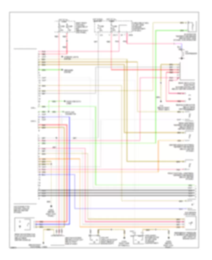
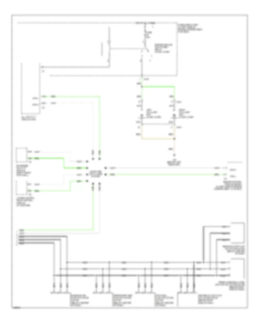
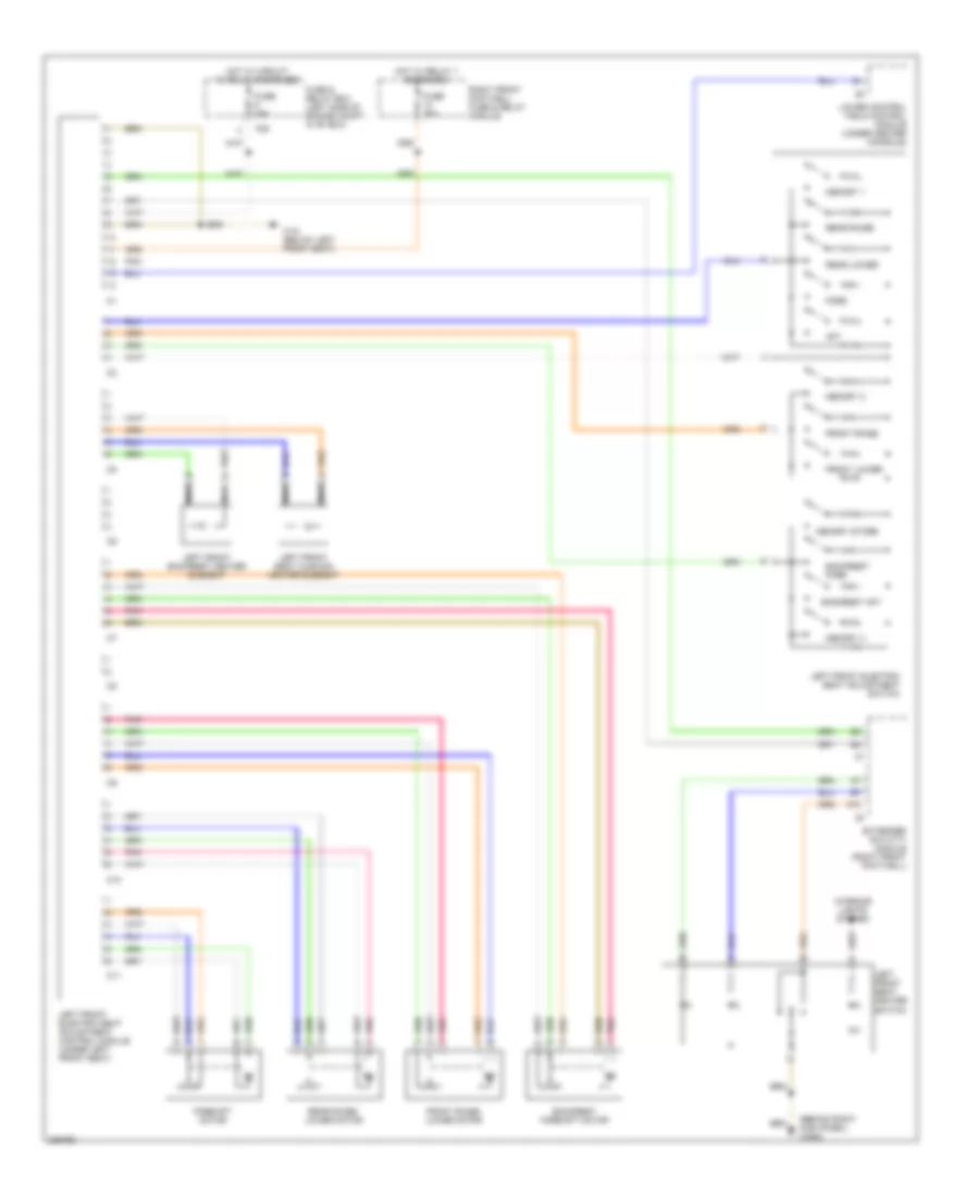
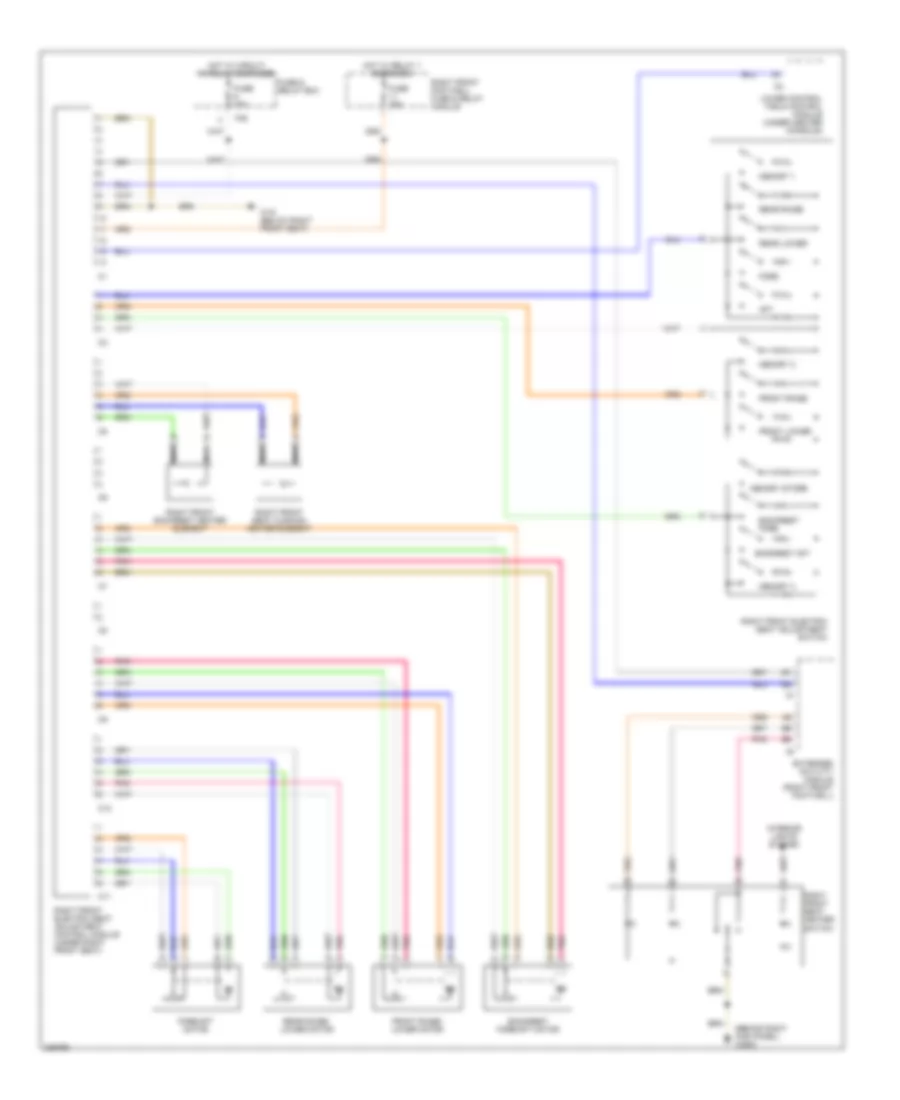
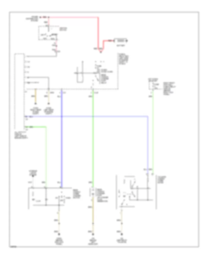
Автомтическая коробка Передач (АКПП) Полная привод (4WD) Блокировка Дифференциала
Электросхема Полного привода 4WD для Mercedes-Benz ML500 2004
 https://portal-diagnostov.com/license.html
Automotive Electricians Portal FZCO
Automotive Electricians Portal FZCO
https://portal-diagnostov.com/license.html
https://portal-diagnostov.com/license.html
Automotive Electricians Portal FZCO
Automotive Electricians Portal FZCO
Электросхема Полного привода 4WD для Mercedes-Benz ML500 2004 - Список элементов:
- (right kick panel) w29/2
- A11
- B10
- Batt
- Can h
- Can l
- Computer data lines system
- Comrtn
- Double combination switch
- Fuse & relay box (left side of engine compt)
- Fuse 15a
- Fuse 25a
- Gnd
- Hot at all times
- Hot in run or start
- Ign
- Illum
- Instrument cluster
- Interior lights system
- Low range ind
- Low range switch
- Mtrccw
- Mtrcw
- Nca
- P/c
- P/d
- Pnk
- Pos 1
- Pos 2
- Pos 3
- Pos 4
- Red
- Right front footwell fuse & relay box (behind right kick panel)
- Sel sw
- Transfer case control module (below center console, behind shift assembly)
- Transfer case range selection motor (left rear of transfer case)
- W18 (under left front seat, under carpet)
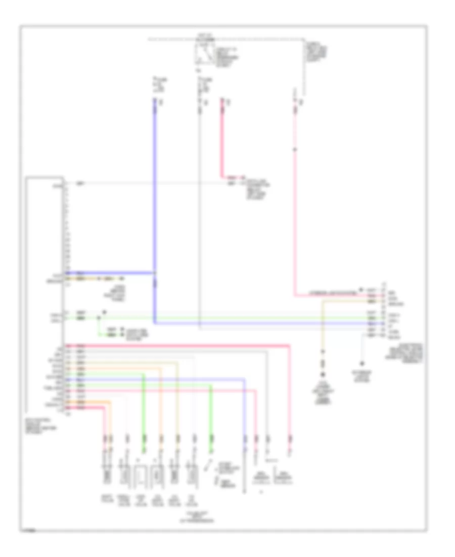
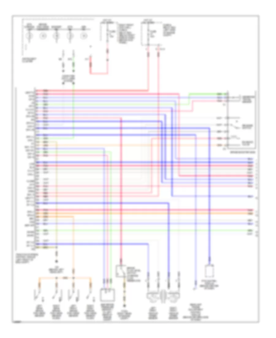
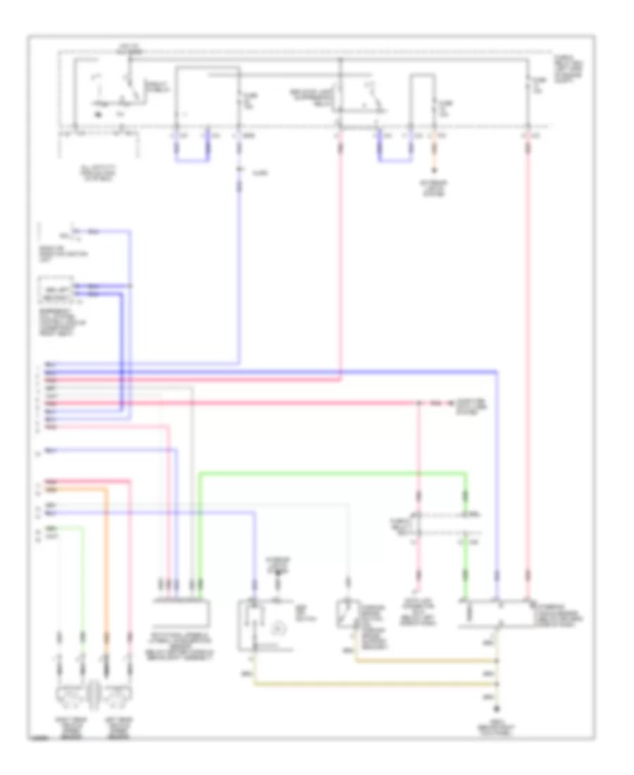
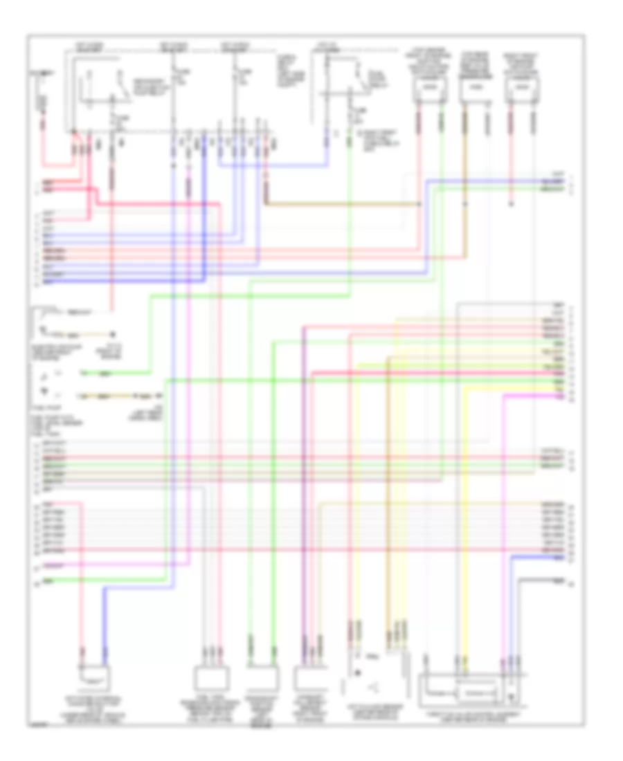
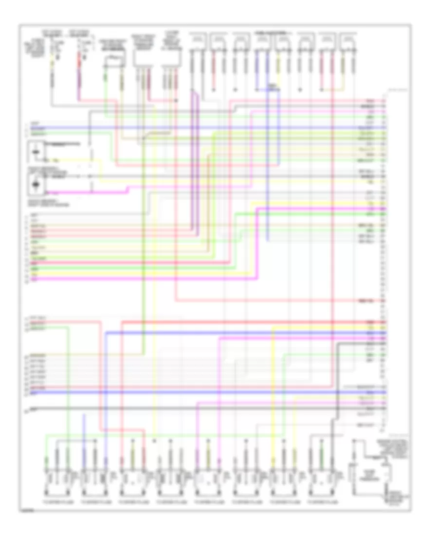
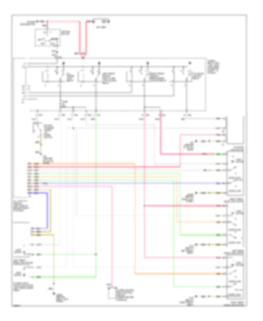
Электросхема автоматической коробки передач АКПП для Mercedes-Benz ML500 2004
Электросхема автоматической коробки передач АКПП для Mercedes-Benz ML500 2004 - Список элементов:
- 1-2/ 4-5 valve
- 15 rs
- 2-3 shift valve
- 3-4 shift valve
- 58d
- C/b
- Can h
- Can l
- Circuit 15 relay (energized in run & start)
- Computer data lines system
- Data link connector (below left side of dash)
- Diag
- Electronic selector lever control module (base of selector assembly)
- Etc control module (behind center of dash)
- Exterior lights system
- Fuse & relay box (left side of engine compt)
- Fuse 15a
- Ground
- Gs+
- Gs-
- Hot at all times
- Interior lights system
- Kl87
- Lock up valve
- Modul- ator valve
- P/b
- P/c
- P/d
- Pnk
- Rpm sensor
- Rs sw
- Shift valve
- Start interlock switch
- Sv1245
- Sv23
- Sv34
- Svkveb
- Temp sensor
- Toel/ask
- Valve unit (etc) (in transmission)
- Vmod
- Vschalt
- W18 (under left front seat, under carpet)
- W29/2 (behind right kick panel)
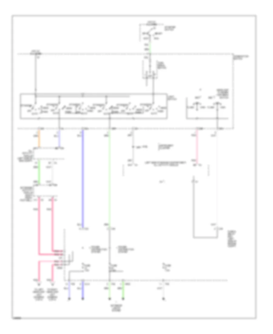
БЛОК ПРЕДОХРАНИТЕЛЕЙ И РЕЛЕ
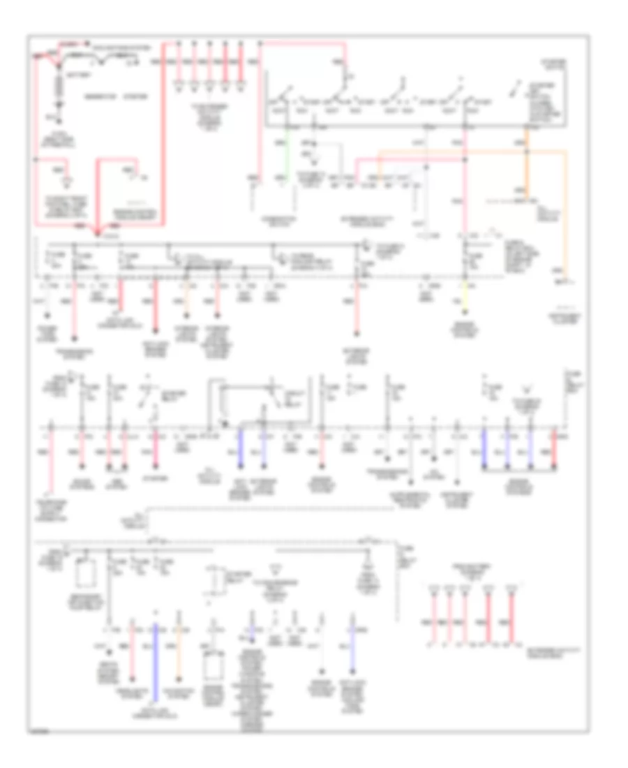
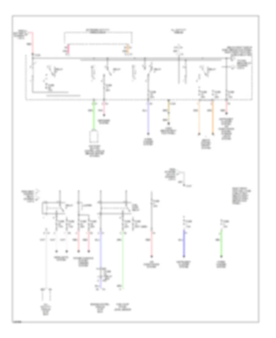
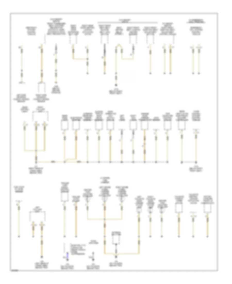
Электросхема блока предохранителей и реле (1 из 4) для Mercedes-Benz ML500 2004
Электросхема блока предохранителей и реле (1 из 4) для Mercedes-Benz ML500 2004 - Список элементов:
- (ml500)
- (not used)
- 15c
- 15r
- A/c system
- A10
- Abs system
- Accy
- All activity module
- Anti- lock brakes system
- Anti-lock brakes system
- Anti-lock brakes system, cooling fans system
- Battery
- C/a
- C/c
- C/d
- C/e
- C/f
- C4 a8
- Circuit relay
- Combination switch
- Cooling fans system
- D/a
- Data link connector (dlc)
- Engine control module (me-sfi)
- Engine controls system
- Engine controls system, power windows system, transmissions system, instrument cluster system, wiper/washer system, mirrors system
- Engine controls systems
- Extended activity module (eam)
- Exterior lights system
- F23
- From battery (diagram 1 of 4)
- From e fuse 18 (diagram 1 of 4)
- From f fuse 19 (diagram 1 of 4)
- From fuse 13 (diagram 1 of 4)
- Fuse
- Fuse & relay box
- Fuse & relay box (in left side of engine compt, in "e" box)
- Fuse 10a
- Fuse 15a
- Fuse 20a
- Fuse 25a
- Fuse 40a
- Generator
- Headlights system
- Instrument cluster
- Instrument cluster system
- Interior lights system
- Interior lights system, instrument cluster system
- M/a
- M/c
- Ml/a
- Mr/a
- Mr/b
- Mr/d
- Mr/e
- Navigation system
- Off
- P/a
- P/b
- P/c
- P/d
- P/e
- P30
- Pnk
- Power tops system
- Red
- Run
- Seats system, memory system
- Secondary air injection pump relay
- Sound systems
- Start
- Starter
- Starter key switch (closed with key in starter switch)
- Starter relay
- Starter switch
- To all activity module (diagram 1 of 4)
- To convenience relay (diagram 2 of 4)
- To extended activity module (diagram 1 of 4)
- To fuse 10 (diagram 2 of 4)
- To fuse 20 (diagram 1 of 4)
- To fuse 21 (diagram 1 of 4)
- To rear foglamp relay (diagram 3 of 4)
- To right front footwell fuse & relay box (diagram 4 of 4)
- Transmission system
- Transmissions system
- W16/4 (right side of firewall)
- X12/12
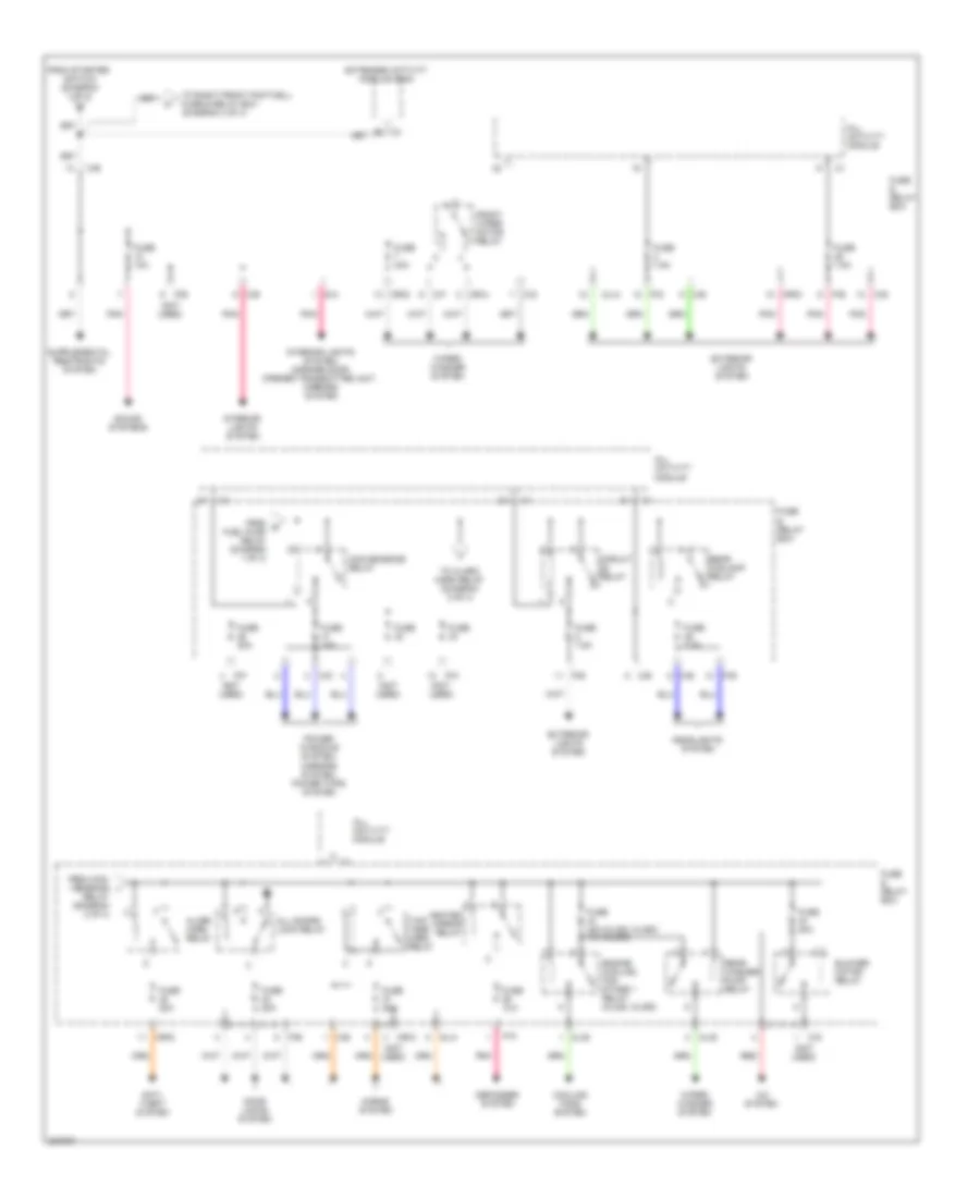
Электросхема блока предохранителей и реле (2 из 4) для Mercedes-Benz ML500 2004
Электросхема блока предохранителей и реле (2 из 4) для Mercedes-Benz ML500 2004 - Список элементов:
- (not used)
- A/c system
- Alarm horn relay
- All activity module
- All doors lock relay
- Anti- theft system
- B5 c3
- Blower motor relay
- C/b
- C/d
- C/e
- C/f
- C/g
- Circuit relay
- Convenience relay
- Cooling fans system
- D/a
- Defogger system
- Door locks system
- Engine cooling fan stage 1 relay (ml320, ml350)
- Extended activity module (eam)
- Exterior lights system
- From con- venience i
- From g fuel pump relay (diagram 1 of 4)
- From starter switch (diagram 1 of 4)
- Front wiper motor relay
- Fuse
- Fuse & relay box
- Fuse 10a
- Fuse 15a
- Fuse 20a
- Fuse 30a
- Fuse 40a (ml320, ml350) 15a (ml500)
- Fuse 7.5a
- Headlights system
- Heated mirror relay
- Horns system
- Interior lights system
- Interior lights system, garage door opener transmitter unit, mirrors system
- Ml/a
- Ml/b
- Mr/a
- Mr/c
- Mr/d
- P/a
- P/b
- P/c
- P/d
- P/e
- P/f
- Pnk
- Power windows system, mirrors system, power tops system
- Rear foglamp relay
- Rear washer pump relay
- Red
- Relay (diagram 2 of 4)
- Sound systems
- To alarm horn relay (diagram 2 of 4)
- To right front footwell fuse & relay box (diagram 4 of 4)
- Two- tone horn relay
- Wiper/ washer system
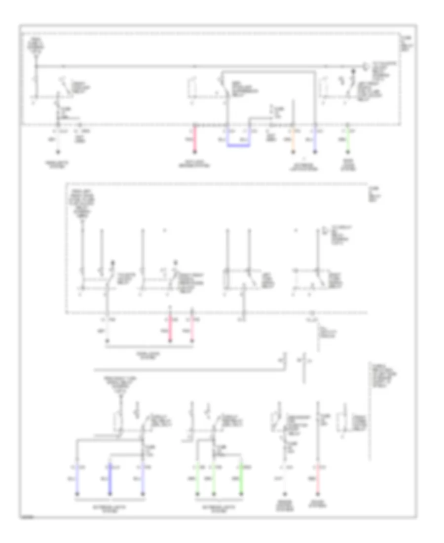
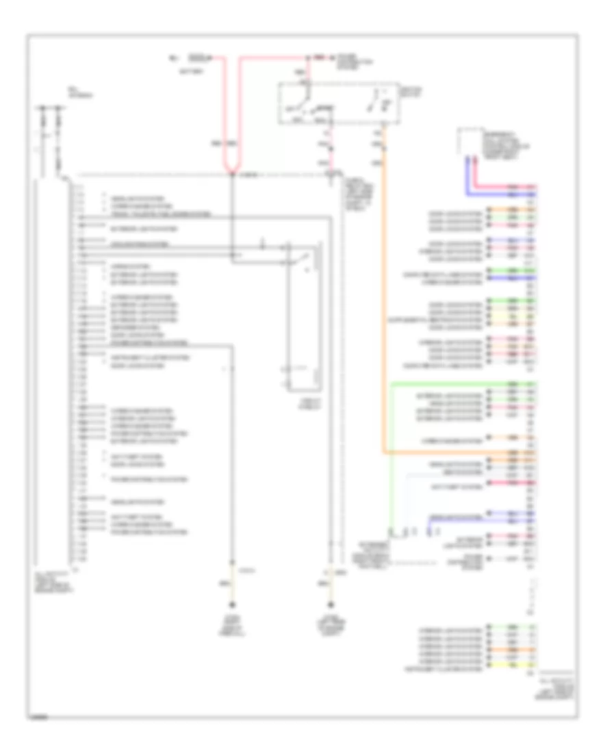
Электросхема блока предохранителей и реле (3 из 4) для Mercedes-Benz ML500 2004
Электросхема блока предохранителей и реле (3 из 4) для Mercedes-Benz ML500 2004 - Список элементов:
- (not used)
- All activity module
- Anti-lock brakes system
- C/c
- C/d
- C/e
- C/f
- C/h
- Circuit 58l relay (drl only)
- Circuit 58r relay (drl only)
- Door locks system
- Engine control systems
- Esp/ stoplamp suppression relay
- Exterior lights system
- From fuse 13 (diagram 1 of 4)
- From left front door & fuel filler flap unlock relay (diagram 3 of 4)
- From right turn signal relay (diagram 3 of 4)
- Front foglamp relay
- Front wiper motor relay
- Fuse & relay box
- Fuse & relay box (in left side of engine compt, in "e" box)
- Fuse 10a
- Fuse 15a
- Fuse 25a
- Fuse 40a
- Fuse 7.5a
- Headlights system
- K10
- Left front door & fuel filler flap unlock relay
- Left turn signal relay
- M/a
- Ml/a
- Ml/c
- Mr/d
- P/b
- P/c
- P/e
- Pnk
- Red
- Right front door & rear doors unlock relay
- Right turn signal relay
- Secondary air injection pump relay
- Sound systems
- Tailgate unlock relay
- To circuit 58l relay (diagram 3 of 4)
- To tailgate unlock relay (diagram 3 of 4)
Электросхема блока предохранителей и реле (4 из 4) для Mercedes-Benz ML500 2004
Электросхема блока предохранителей и реле (4 из 4) для Mercedes-Benz ML500 2004 - Список элементов:
- (below right side of dash, behind kick panel) right front footwell fuse & relay box
- A12 c4
- A8 c3
- Aac push- button control module (behind center of dash)
- Air conditioning system
- All activity module
- All activity module (in "e" box)
- B12
- C/d
- Defogger system
- Engine control module (in "e" box)
- Extended activity module (eam)
- From battery a (diagram 1 of 4)
- From seat l comfort relay (diagram m 4 of 4)
- From starter switch (diagram 2 of 4)
- Fuel pump & fuel level sensor
- Fuel pump relay
- Fuse & relay box
- Fuse (not used)
- Fuse 15a
- Fuse 20a
- Fuse 25a
- Fuse 30a
- Fuse 35a
- Fuse 40a
- Fuse 7.5a
- Fuse 70a
- Headlights system
- Instrument cluster system
- Instrument cluster system, air conditioning system, interior lights system
- Jumper
- P/d
- Pnk
- Power windows system, mirrors system
- Red
- Relay
- Right front footwell fuse & relay box (below right side of dash, behind kick panel)
- Seats system, memory system
- To high beam relay (diagram 4 of 4)
- W29/2 (behind right kick panel)
- Wiper/ washer system
- X12/6
- X12/7
- X12/9
БЛОКИ УПРАВЛЕНИЯ КУЗОВОМ
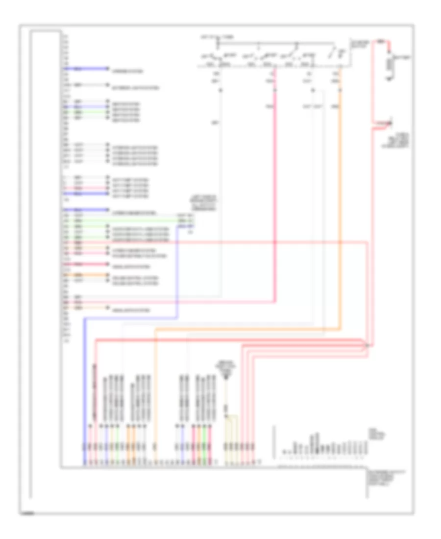
вся схема модуля деятельности для Mercedes-Benz ML500 2004
вся схема модуля деятельности для Mercedes-Benz ML500 2004 - Список элементов:
- 15c
- A10
- A11
- A12
- Acc
- All activity module (left side of engine compt)
- Anti-theft system
- B10
- B11
- B12
- Battery
- C/d
- Circuit 15 relay
- Computer data lines system
- Cooling fans system
- Defogger system
- Door locks system
- Emergency call system control module (under right front seat)
- Extended activity module (eam) (right front footwell)
- Exterior lights system
- Fuse & relay box (left side of engine compt, in "e" box)
- Headlights system
- Horns system
- Ignition switch
- Instrument cluster system
- Interior lights system
- Key in
- Mr/d
- Nca
- Off
- Pnk
- Power distribution system
- Rcl antenna
- Red
- Run
- Seats system
- Start
- Trunk, tailgate, fuel doors system
- W16/4 (right side of firewall)
- W16/5 (left rear of engine compt)
- Wiper/washer system
- X12/12
- X12/14
расширенная схема модуля деятельности для Mercedes-Benz ML500 2004
расширенная схема модуля деятельности для Mercedes-Benz ML500 2004 - Список элементов:
- (behind right kick panel) w29/2
- (left side of engine compt) all activity module (aam)
- 15c
- 15r
- A10
- A11
- A12
- Acc
- Anti-theft system
- B10
- B11
- B12
- Battery
- Clock
- Computer data lines system
- Cruise control system
- Das control module
- Data 0
- Data 1
- Data 2
- Data 3
- Diagnosis
- Extended activity module (eam) (right front footwell)
- Exterior lights system
- Fuse & relay box (left rear of eng compt)
- Headlights system
- Hot at all times
- Immobilizer
- Inhibit
- Interior lights system
- Key in
- Ki 15
- Ki 15c
- Mirrors system
- Off
- Pnk
- Power distribution system
- Read
- Red
- Run
- Seats system
- Seats, memory systems
- Start
- Starter switch
- Temp
- Wiper/washer system
- Write
- X12/12
ВНЕШНЕЕ ОСВЕЩЕНИЕ
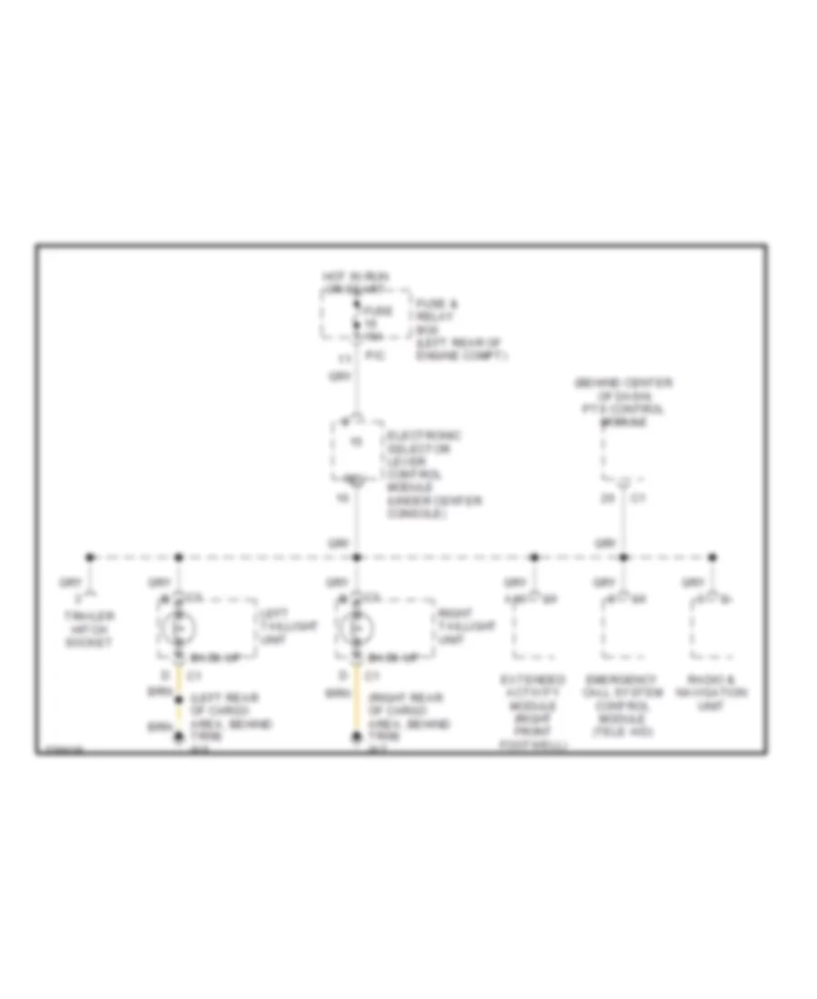
Электросхема заднего хода для Mercedes-Benz ML500 2004
Электросхема заднего хода для Mercedes-Benz ML500 2004 - Список элементов:
- (behind center of dash) pts control module
- (left rear of cargo area, behind trim) w6
- (right rear of cargo area, behind trim) w7
- A10
- Back-up
- Electronic selector lever control module (under center console)
- Emergency call system control module (tele aid)
- Extended activity module (right front footwell)
- Fuse & relay box (left rear of engine compt)
- Fuse 15a
- Hot in run or start
- Left taillight unit
- P/c
- Radio & navigation unit
- Rev
- Right taillight unit
- Trailer hitch socket
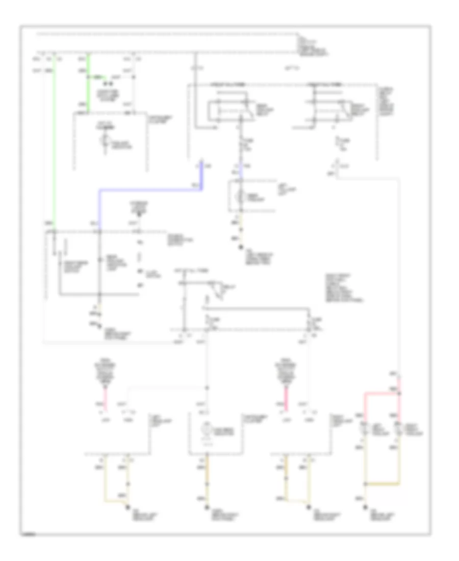
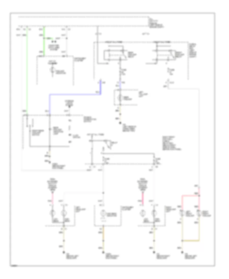
Электросхема внешнего освещения (1 из 2) для Mercedes-Benz ML500 2004
Электросхема внешнего освещения (1 из 2) для Mercedes-Benz ML500 2004 - Список элементов:
- 56a
- 56d
- 58l
- 58r
- A11
- A13
- Accy
- All activity module
- All activity module (left side of engine compt)
- Auto
- B10
- C/b
- C/d
- C/e
- Combination switch
- Flash
- Fuse & relay box (left side of engine compt)
- Fuse 7.5a
- Hazard flasher switch
- Head
- Headlamp flasher/ high beam switch
- Headlights system
- High
- Hot at all times
- Instrument cluster
- Left rear tailgate door license plate lamp
- Left spare wheel carrier license plate lamp
- Light switch
- Low
- Ml/a
- Mr/d
- Off
- P/b
- P/e
- P30
- Park
- Pnk
- Right rear tailgate door license plate lamp
- Right spare wheel carrier license plate lamp
- Run
- Standing
- Start
- Starter switch
- To left headlamp unit (diagram 2 of 2)
- To left taillamp unit (diagram 2 of 2)
- To right headlamp unit (diagram 2 of 2)
- To right taillamp unit (diagram 2 of 2)
- Turn signal switch
- W/ spare tire carrier
- W29/2 (behind right kick panel)
- W6 (left rear of cargo area, behind trim)
- W8 (on tailgate, behind trim)
Электросхема внешнего освещения (2 из 2) для Mercedes-Benz ML500 2004
Электросхема внешнего освещения (2 из 2) для Mercedes-Benz ML500 2004 - Список элементов:
- (4)
- (left rear of cargo area) w6
- (right kick panel) w29/2
- (right rear of cargo area) w7
- A10
- All activity module (left side of eng compt)
- Back-up lights
- Bla
- C/c
- C/e
- C/f
- C/h
- Center high mounted stoplamp
- Center high mounted stoplamp (w/ spare wheel carrier)
- Circuit
- Circuit relay
- Esp stoplight suppres- sion relay
- From fuse 12 (diagram 1 of 2)
- From fuse 24 (diagram 1 of 2)
- Fuse & relay box (left side of engine compt)
- Fuse 10a
- Fuse 25a
- Fuse 7.5a
- Hot at all times
- Instrument cluster
- Left headlamp unit
- Left outside mirror
- Left taillamp unit
- Left turn ind
- Left turn signal relay
- Ml/a
- Mr/d
- Nca
- P/a
- P/c
- P/d
- P/e
- Pnk
- Red
- Right headlamp unit
- Right outside mirror
- Right taillamp unit
- Right turn ind
- Right turn signal relay
- Side marker
- Stop
- Tail/ parking (2)
- Traction systems control module (left front of eng compt)
- Trailer hitch socket
- Trailer turn signal control module (integral to trailer harness)
- Turn signal
- W2 (behind right headlamp)
- W29/2 (behind right kick panel)
- W29/2 (right kick panel)
- W6 (left rear of cargo area, behind trim)
- W8 (on tailgate, behind trim)
- W9 (behind left headlamp)
ВНУТРЕННЕЕ ОСВЕЩЕНИЕ
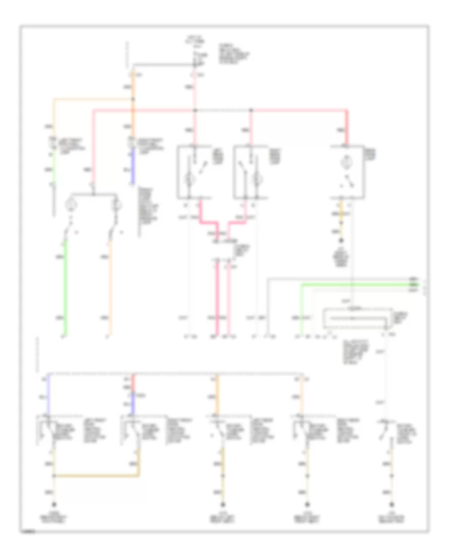
Электросхема подсветки (1 из 2) для Mercedes-Benz ML500 2004
Электросхема подсветки (1 из 2) для Mercedes-Benz ML500 2004 - Список элементов:
- All activity module (aam) (in left side of engine compt, in "e" box)
- B11
- C/c
- D/a
- D/b
- Front dome lamp (with shut-off delay & front reading lamp)
- Fuse & relay box
- Fuse & relay box (in left side of engine compt, in "e" box)
- Fuse 10a
- Hot at all times
- Left front door central locking actuating motor
- Left front footwell illumination lamp
- Left rear dome lamp
- Left rear door central locking actuating motor
- P/d
- P/f
- Pnk
- Rear dome lamp
- Red
- Right front door central locking actuating motor
- Right front footwell illumination lamp
- Right rear dome lamp
- Right rear door central locking actuating motor
- Rotary tumbler micro- switch
- Rotary tumbler/ trunk lid micro- switch
- W18 (below left front seat)
- W19 (below right front seat)
- W29/2 (behind right kick panel)
- W7 (right rear of cargo area)
- W8 (on tailgate, behind trim)
- X35/2
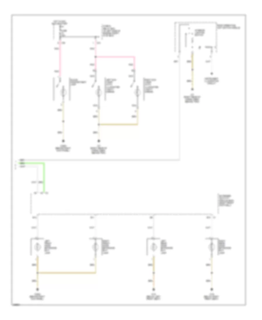
Электросхема подсветки (2 из 2) для Mercedes-Benz ML500 2004
Электросхема подсветки (2 из 2) для Mercedes-Benz ML500 2004 - Список элементов:
- B10
- B11
- B12
- C/b
- D/a
- Extended activity module (eam) (right front footwell)
- Fuse & relay box (in left side of engine compt, in "e" box)
- Fuse 10a
- Glove compartment lamp
- Hot in acc, run or start
- Instrument illumination circuit
- Interior lighting switch
- Left front door entrance/ exit lamp
- Left rear door entrance/ exit lamp
- Left sun visor (with illuminated vanity mirror)
- Nca
- Pnk
- Right front door entrance/ exit lamp
- Right rear door entrance/ exit lamp
- Right sun visor (with illuminated vanity mirror)
- Roof operating unit switch module
- W18 (below left front seat)
- W19 (below right front seat)
- W29/2 (behind right kick panel)
- W7 (right rear of cargo area, behind trim)
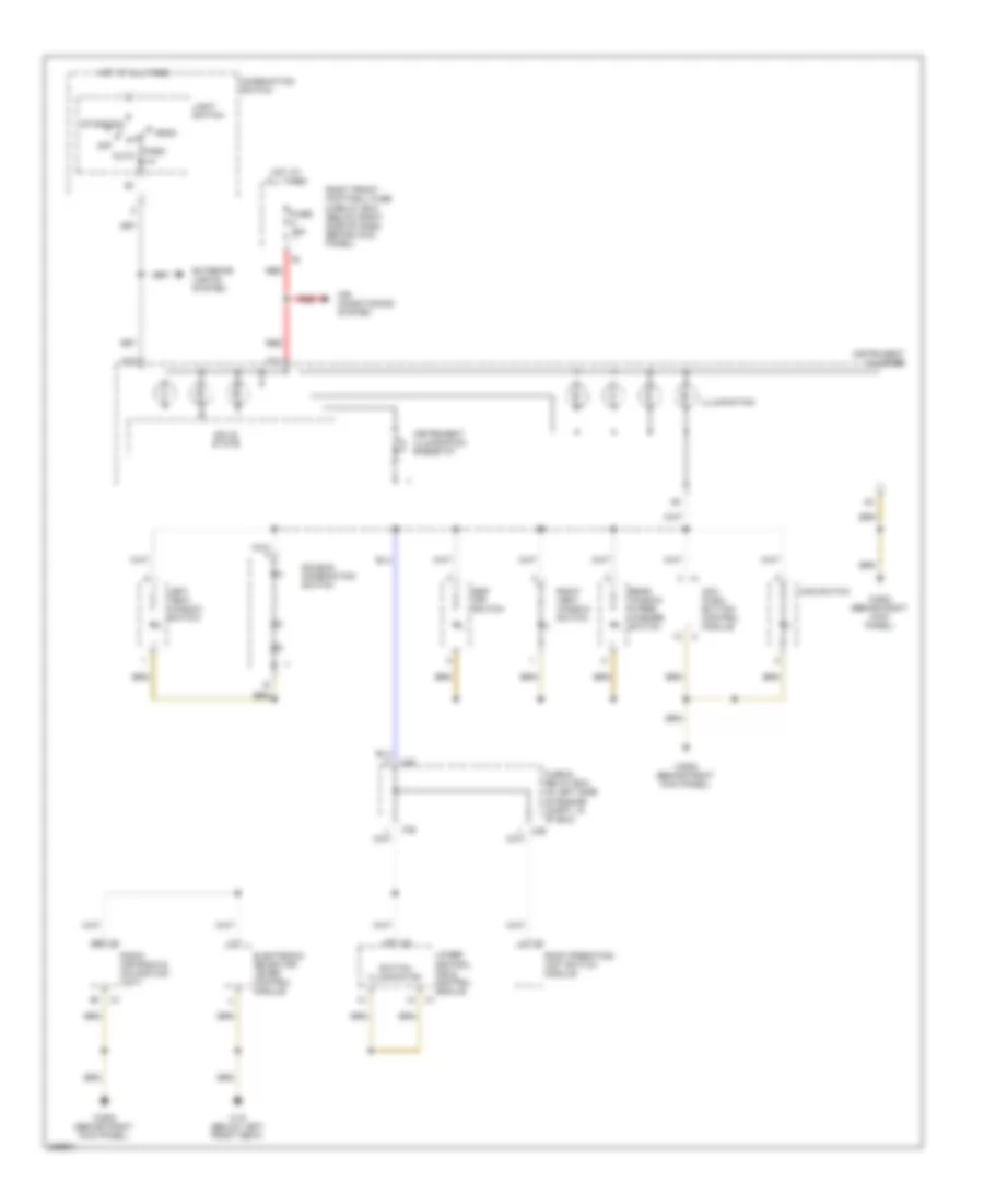
Электросхема подсветки приборов для Mercedes-Benz ML500 2004
Электросхема подсветки приборов для Mercedes-Benz ML500 2004 - Список элементов:
- A11
- A13
- Acc push- button control module
- Air conditioning system
- Auto
- C/e
- C1 a6
- Combination switch
- D/b
- Double combination switch
- Electronic selector lever control module
- Esp off switch
- Exterior lights system
- Fuse & relay box (in left side of engine compt, in "e" box)
- Fuse 15a
- Hcs switch
- Head
- Hot at all times
- Illumination
- Instrument cluster
- Instrument illumination rheostat
- Left vent window switch
- Light switch
- Lower control field control module
- Off
- P/e
- Park
- Radio (or radio & navigation unit)
- Rear window wiper/ washer switch
- Red
- Right front footwell fuse & relay box (below right side of dash, behind kick panel)
- Right vent window switch
- Roof operating unit switch module
- Solid state
- Standing
- Switch illumination
- W18 (below left front seat)
- W29/2 (behind right kick panel)
ЗАЗЕМЛЕНИЕ ПОДКЛЮЧЕНИЕ МАССЫ
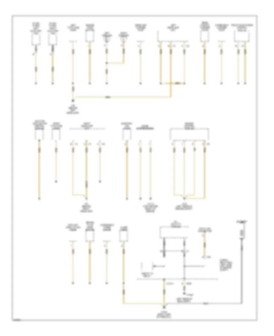
Электросхема подключение массы заземления (1 из 3) для Mercedes-Benz ML500 2004
Электросхема подключение массы заземления (1 из 3) для Mercedes-Benz ML500 2004 - Список элементов:
- rn
- (left rear of eng compt)
- (ml320, ml350) left auxiliary fan
- (ml320, ml350) right auxiliary fan
- Alarm horn
- All activity module
- Battery
- Brake fluid level switch
- C/b
- Circuit 15 relay
- Coolant circulation pump
- Data link connector
- Electric air pump
- Engine control module
- Engine hood switch
- Fuse & relay box (left side of engine compt)
- Headlamp washer pump
- Left foglamp
- Left headlamp unit
- Left two-tone horn
- Mr/d
- Nca
- Noise suppressors
- Rear window washer pump
- Right foglamp
- Right headlamp unit
- Right two-tone horn
- Suction cooling fan control module
- Traction systems control module
- W11/3 (top center front of engine)
- W16 (left rear of engine compt)
- W16/4 (right side of firewall)
- W16/5
- W2 (behind right headlamp)
- W9 (behind left headlamp)
- Windshield washer pump
- Windshield wiper motor
- X12/14
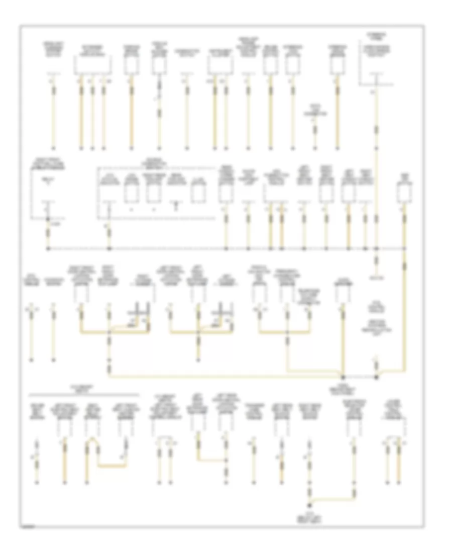
Электросхема подключение массы заземления (2 из 3) для Mercedes-Benz ML500 2004
Электросхема подключение массы заземления (2 из 3) для Mercedes-Benz ML500 2004 - Список элементов:
- (w/ memory seats) left front electric seat adjustment control module
- A12
- Aac pushbutton control module
- Ata status indicator
- Audio amplifier
- Combination switch
- Cruise control switch
- Data link connector
- Double combination switch
- Driver seat belt switch
- Electronic selector lever control module
- Esp off switch
- Etc control module
- Extended activity module (eam)
- Frequency change-over control module
- Front/rear foglamp switch
- Glove com- partment lamp
- Headlamp range adjustment control module
- Headlight cleaning system switch
- Heating systems recirculation unit
- Horn/air bag clock spring contact
- Illum- ination
- Instrument cluster
- Kickdown switch
- Left front door central locking actuating motor
- Left front door entrance/ exit lamp
- Left front electric seat adjustment switch
- Left front seat cushion heater element
- Left front seat heater switch
- Left outside mirror
- Left rear door central locking actuating motor
- Left rear door entrance/ exit lamp
- Left rear seat belt buckle switch
- Left vent window switch
- Low range switch
- Lower control field control module
- Module box blower motor
- Nca
- Parking brake switch
- Pts control module
- Radio & navigation unit (or radio)
- Rear foglamp indicator
- Rear window wiper/ washer switch
- Relay
- Right front door central locking actuating motor
- Right front door entrance/ exit lamp
- Right front footwell fuse & relay module
- Right front seat heater switch
- Right outside mirror
- Right rear seat belt buckle switch
- Right vent window switch
- Seat heater relay (stage 1)
- Steering angle sensor
- Steering wheel
- Steering- lock switch
- Transfer case control module
- W/o memory seats
- W18 (below left front seat)
- W29/2 (behind right kick panel)
- X12/6
Электросхема подключение массы заземления (3 из 3) для Mercedes-Benz ML500 2004
Электросхема подключение массы заземления (3 из 3) для Mercedes-Benz ML500 2004 - Список элементов:
- (w/ memory seats) right front electric seat adjustment control module
- (w/o memory seats) front passenger seat occupied recognition switch w/ acsr (automatic child seat recognition)
- A c1
- Antenna splitter
- Center high mounted stoplamp
- D c1
- Electrolytic capacitor (rear window noise suppressor)
- Electronic compass
- Emergency call system control module
- Fm/am amplifier
- Fuel pump w/ level sensor
- Garage door opener transmitter
- Interior rearview mirror assembly
- Left side air bag & window air bag sensor
- Left spare wheel carrier license plate lamp
- Left sun visor
- Left tailgate door license plate lamp
- Left taillamp unit
- Nca
- Rain sensor
- Rear dome light
- Rear ventilation electronic blower controller
- Restraint system control module
- Right front electric seat adjustment switch
- Right front seat belt buckle/ belt lock switch
- Right front seat cushion heater element
- Right rear door central locking actuating motor
- Right rear door entrance/ exit lamp
- Right side air bag & window air bag sensor
- Right spare wheel carrier license plate lamp
- Right sun visor
- Right tailgate door license plate lamp
- Right taillamp unit
- Roof operating unit switch module
- Rotary tumbler/ trunk lid microswitch
- Sdar control unit
- Seat heater relay (stage 1)
- Sliding/ pop-up roof drive assembly
- Tailgate central locking actuating motor
- Tailgate window wiper motor
- Trailer hitch socket
- Trailer turn signal control module
- Trip computer control module
- Voice control system control module
- W/ emergency call (tele aid)
- W/ spare tire carrier
- W/o memory seats
- W19 (below right front seat)
- W26 (below center console)
- W6 (left rear of cargo area, behind trim)
- W7 (right rear of cargo area, behind trim)
- W8 (on tailgate, behind trim)
Звуковой сигнал Гудок
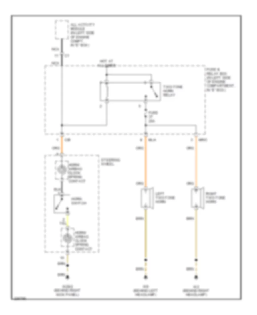
Электросхема звукового сигнал Гудка для Mercedes-Benz ML500 2004
Электросхема звукового сигнал Гудка для Mercedes-Benz ML500 2004 - Список элементов:
- All activity module (in left side of engine compt, in "e" box)
- C/b
- Fuse 20a
- Fuse & relay box (in left side of engine compartment, in "e" box)
- Horn switch
- Horn/ airbag clock spring contact
- Hot at all times
- Left two-tone horn
- Ml/a
- Mr/c
- Nca
- Right two-tone horn
- Steering wheel
- Two-tone horn relay
- W2 (behind right headlamp)
- W29/2 (behind right kick panel)
- W9 (behind left headlamp)
Магнитола Мультимедия
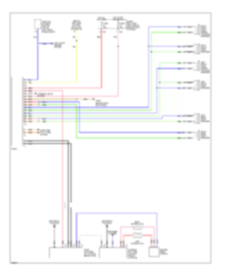
Эдектросхема магнитолы. Базовая комплектация. для Mercedes-Benz ML500 2004
Эдектросхема магнитолы. Базовая комплектация. для Mercedes-Benz ML500 2004 - Список элементов:
- (behind right kick panel)
- (below left side of dash) data link connector
- (center of tailgate) w8
- Antenna splitter (on right side of liftgate)
- Anti-locks brakes system
- Computer data lines system
- Defogger system
- Fm/am amplifier (in liftgate, behind trim)
- Fuse & relay box (left side of engine compt, in "e" box)
- Fuse 10a
- Fuse 15a
- Heated rear window
- Hot at all times
- Hot in off, acc or run
- Interior lights system
- Left antenna coil
- Left front door mirror triangle speaker
- Left front door speaker
- Left rear door speaker
- Nca
- Nca s
- P/b
- P/d
- Pnk
- Pnk a
- Radio
- Red
- Red b
- Right antenna coil
- Right front door mirror triangle speaker
- Right front door speaker
- Right rear door speaker
- Traction systems control module (left front of eng compt)
- W29/2
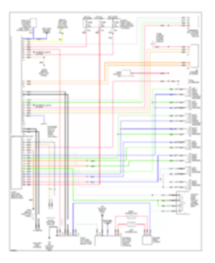
Электросхема магнитолы Bose для Mercedes-Benz ML500 2004
Электросхема магнитолы Bose для Mercedes-Benz ML500 2004 - Список элементов:
- (behind right kick panel)
- (below left side of dash) data link connector
- (on tailgate, behind trim)
- Acousti- mass bass module (under driver's seat)
- Antenna splitter (on right side of liftgate)
- Anti-lock brakes system
- Audio amplifier (behind left side of dash)
- C1 a4
- Cd changer (in trunk)
- Ctel interface
- Ctel/gps roof antenna
- Defogger system
- Emergency call system control module
- Extended activity module (right front footwell)
- Exterior lights system
- Fm/am amplifier (in liftgate, behind trim)
- Fuse & relay box (left side of engine compt, in "e" box)
- Fuse 10a
- Fuse 15a
- Fuse 25a
- Heated rear window
- Hot at all times
- Hot in off, acc or run
- Interior lights system
- K10 red
- Left antenna coil
- Left front door mirror triangle speaker
- Left front door speaker
- Left rear door speaker
- Left rear speaker
- Nca
- Nca s
- P/b pnk
- P/d red
- Pnk
- Pnk a
- Radio & navigation unit
- Red
- Red b
- Right antenna coil
- Right front door mirror triangle speaker
- Right front door speaker
- Right rear door speaker
- Right rear speaker
- Sdar control unit
- Sound amplifier module
- Traction systems control module (left front of eng compt)
- Voice control system control module
- W29/2
- W29/2 (behind right kick panel)
- W8 (on tailgate, behind trim)
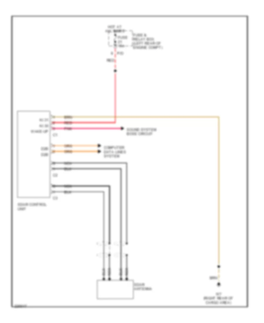
Электросхема спутникового радио для Mercedes-Benz ML500 2004
Электросхема спутникового радио для Mercedes-Benz ML500 2004 - Список элементов:
- Computer data lines system
- D2b
- Fuse & relay box (left rear of engine compt)
- Fuse 15a
- Hot at all times
- Ki.30
- Ki.31
- Nca
- P/d
- Pnk
- Red
- Sdar antenna
- Sdar control unit
- Sound system bose circuit
- W7 (right rear of cargo area)
- Wake-up
Навигация GPS Парктроники
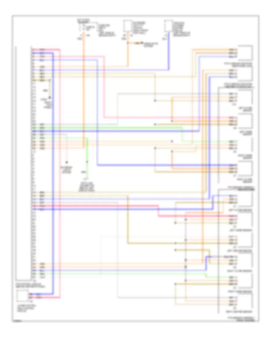
Электросхема парктроников для Mercedes-Benz ML500 2004
Электросхема парктроников для Mercedes-Benz ML500 2004 - Список элементов:
- (right kick panel)
- C/e
- C10
- Data link connector (below left side of dash)
- Extended activity module (right front footwell)
- Exterior lights system
- Fuse 22 15a
- Fuse and relay box (left side of engine compt)
- Headlights system
- Hot in run or start
- Left center sensor
- Left inner sensor
- Left outer sensor
- Lower control field control module
- Pnk
- Pts control module (behind center of dash)
- Pts sensor assembly (front bumper)
- Pts sensor assembly (rear bumper)
- Pts warning indicator (center i/p air outlet)
- Pts warning indicator (rear dome lamp)
- Right center sensor
- Right inner sensor
- Right outer sensor
- Traction systems control module (left front of engine compt)
- W29/2
Подогрев стекол и зеркал
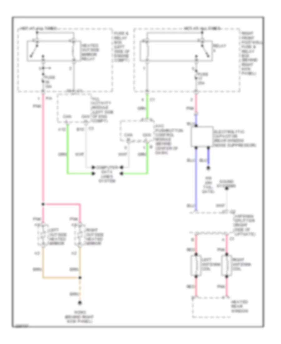
Электросхема подогрева стекол и зеркал для Mercedes-Benz ML500 2004
Электросхема подогрева стекол и зеркал для Mercedes-Benz ML500 2004 - Список элементов:
- A12
- Aac pushbutton control module (behind center of dash)
- All activity module (left side of eng compt)
- Antenna splitter (right side of liftgate)
- C1 a
- C3 b12
- Can h
- Can l
- Computer data lines system
- Electrolytic capacitor (rear window noise suppressor)
- Fuse & relay box (left side of engine compt)
- Fuse 10a
- Fuse 25a
- Heated outside mirror relay
- Heated rear window
- Hot at all times
- Left antenna coil
- Left outside heated mirror
- P/a
- Pnk
- Red
- Relay
- Right antenna coil
- Right front footwell fuse & relay box (behind right kick panel)
- Right outside heated mirror
- Sound systems
- W29/2 (behind right kick panel)
- W8 (on tail- gate)
ПОДУШКИ БЕЗОПАСНОСТИ AIR BAG
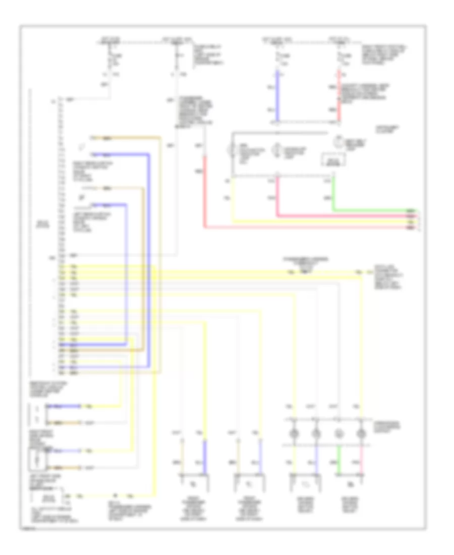
Электросхема подушек безопасности SRS AirBag (1 из 2) для Mercedes-Benz ML500 2004
Электросхема подушек безопасности SRS AirBag (1 из 2) для Mercedes-Benz ML500 2004 - Список элементов:
- (cockpit harness, near breakout for center nozzle air stream temperature sensor) z50/32
- (dtc readout) (partial) (below left side of dash)
- (passenger harness, under front of center console, near breakout for radio & srs control module) z52/15
- (passenger's harness, in breakout to x18) z51/16
- 15r
- A11
- A15
- A18
- Air bag off indicator lamp
- All activity module (aam) (left side of engine compartment in "e" box)
- Data link connector
- Driver's air bag ignition squib 1
- Driver's air bag ignition squib 2
- Front passenger air bag (ab) squib 1 (on right side of dash)
- Front passenger air bag (ab) squib 2 (on right side of dash)
- Fuse & relay box (left side of engine compartment)
- Fuse 15a
- Fuse 7.5a
- Horn/air bag clock spring contact
- Hot at all times
- Hot in off, acc or on
- Hot in on or start
- Instrument cluster
- Left front side air bag squib (in left front door)
- Left rear curtain (window) air bag squib (at left "c"pillar)
- P/b
- P/c
- Pnk
- Red
- Restraint system control module (under center console)
- Right front footwell fuse & relay module (below right side of dash, behind kick panel)
- Right front side air bag squib (in right front door)
- Right rear curtain (window) ignition squib (at right "c" pillar)
- Seat belt reminder lamp
- Solid state
- Srs malfunction indicator lamp (mil)
- Z51/14 (passenger harness, left side of engine compartment, in "e" box)
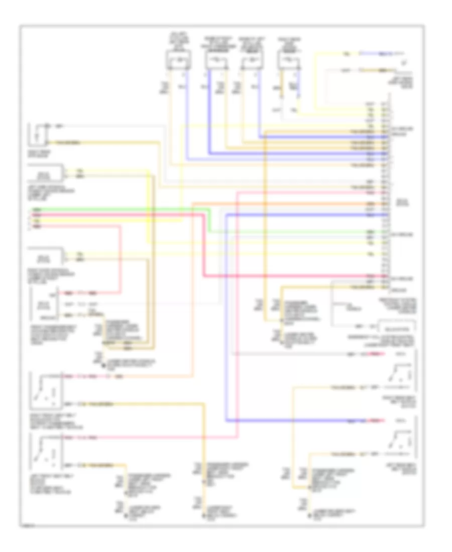
Электросхема подушек безопасности SRS AirBag (2 из 2) для Mercedes-Benz ML500 2004
Электросхема подушек безопасности SRS AirBag (2 из 2) для Mercedes-Benz ML500 2004 - Список элементов:
- (base of left "b" pillar) driver etr squib
- (base of right "b" pillar) front passenger etr squib
- (on left "c" pillar) left rear etr squib
- (passenger harness, under center console in plastic harness channel) z53/9
- (passenger harness, under left front seat, near breakout for ground w18) z51/9
- (passenger harness, under right front seat, near breakout for x52) z52/1
- (under center console, on srs mounting bolt) w26
- (under driver's seat, below carpet) w18
- (under right front seat, below carpet) w19
- 15r
- Emergency call system control module (tele aid) (under right front seat)
- Front passenger seat occupied recognition w/automatic child seat recognition (ascr)
- Ground
- Left front seat belt buckle switch (in driver's seat, in seatbelt buckle)
- Left rear seat belt buckle switch
- Left rear side air bag squib
- Left side air bag & window air bag sensor (under left "b" pillar)
- Pnk
- Red
- Restraint system control module (under center console)
- Right door air bag & window air bag sensor (under of right "b" pillar)
- Right front seat belt buckle switch (in front passenger's seat, in seatbelt buckle)
- Right rear etr squib
- Right rear seat belt buckle switch
- Right rear side air bag squib
- Solid state
- Sw ground
- Us models
ПРИБОРНАЯ ПАНЕЛЬ
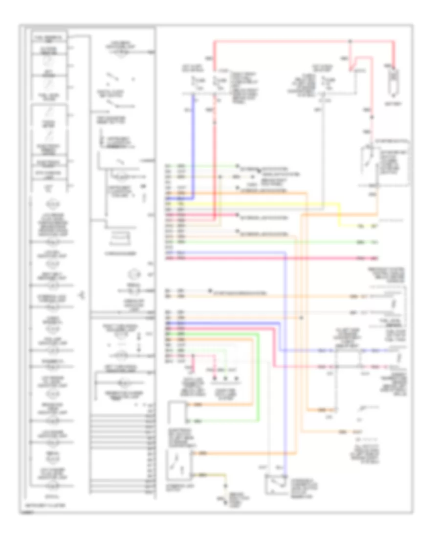
Электросхема панели приборов для Mercedes-Benz ML500 2004
Электросхема панели приборов для Mercedes-Benz ML500 2004 - Список элементов:
- (behind right kick panel)
- (behind right kick panel) w29/2
- (in left side of engine compartment) fuse & relay box
- 15c
- A10
- A11
- A12
- A13
- A14
- A15
- A16
- A17
- A18
- Abs mil
- Airbag off indicator lamp
- All activity module (aam) (in left side of engine compt, in "e" box)
- Ambient temperature sensor (behind left side of front grille)
- B10
- B11
- B12
- Bas/esp mil
- Battery
- Brake pad wear indicator lamp
- C/c
- C/d
- Check engine mil
- Computer data lines system
- Data link connector (partial) (below left side of dash)
- Digital clock set switch
- Ect gauge
- Electronic clock
- Electronic ecl switch (in left rear of engine compartment)
- Electronic speedo- meter
- Ets mil
- Ets warning lamp
- Exterior lights system
- Fog lamp indicator lamp
- Fuel level gauge
- Fuel level sensor
- Fuel pump (on top of fuel tank)
- Fuel reserve ind
- Fuse & relay box (in left side of engine compartment, in "e" box)
- Fuse 15a
- Fuse 7.5a
- Generator charge indicator lamp
- Headlights system
- High beam indicator lamp
- Hot in off, acc or run
- Hot in run or start
- Instrument cluster
- Instrument illumination (3 bulbs)
- Instrument illumination rheostat
- Interior lights system
- Left turn signal indicator lamp
- Limit mil
- Low brake fluid level/ parking brake/ brake-force proportioning indicator lamp
- Low ecl indicator lamp
- Low engine oil level indicator lamp
- Low range indicator lamp
- Low washer fluid level indicator lamp
- Ml/a
- Outside temp ind
- Pnk
- Red
- Restraint system control module (below center console)
- Right front footwell fuse & relay box (below right side of dash, behind kick panel)
- Right turn signal indicator lamp
- Seat belt reminder lamp
- Srs mil
- Starter key switch (closed w/key in starter switch)
- Starter switch
- Starting/charging system
- Steering lock switch
- Steering lock warning lamp
- Tacho- meter
- Trip odometer reset button
- W29/2
- Warning buzzer
- Windshield washer fluid level switch (in fluid reservoir)
- X12/12
- X12/9
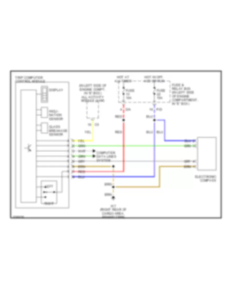
Электросхема бортового компьютера для Mercedes-Benz ML500 2004
Электросхема бортового компьютера для Mercedes-Benz ML500 2004 - Список элементов:
- (in left side of engine compt, in "e" box) all activity module (aam)
- Computer data lines system
- D/a
- Display
- Electronic compass
- Fuse & relay box (in left side of engine compartment, in "e" box)
- Fuse 10a
- Fuse 15a
- Glass breakage sensor
- Hot at all times
- Hot in off, acc or run
- Incli- nation sensor
- Left
- P/d
- Red
- Right
- Trip computer control module
- W7 (right rear of cargo area, behind trim)
ПРИВОД ЗЕРКАЛ
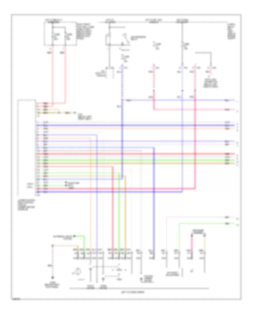
Электросхема привода зеркал (1 из 2) для Mercedes-Benz ML500 2004
Электросхема привода зеркал (1 из 2) для Mercedes-Benz ML500 2004 - Список элементов:
- (4)
- (below left side of dash)
- All activity module
- C/b
- Can h
- Can l
- Computer data lines
- Convenience relay
- D/a
- Data link connector
- Day/night adjustment
- Defogger system
- Exterior lights system
- Folding mirror motor
- Fuse & relay box (left side of engine compt)
- Fuse 10a
- Fuse 15a
- Fuse 25a
- Hot at all times
- Hot in off, acc and run
- Hot in run and start
- Hot w/ relay 8 energized
- In/out motor
- Left outside mirror
- Lower control field control module (under center console)
- Nca
- P/b
- P/c
- P/d
- Pnk
- Red
- Right front footwell fuse & relay box (below right side of dash, behind kick panel)
- Up/dn motor
- W18 (below left front seat)
- W29/2 (behind right kick panel)
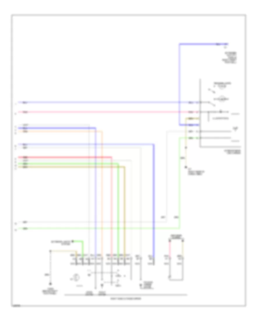
Электросхема привода зеркал (2 из 2) для Mercedes-Benz ML500 2004
Электросхема привода зеркал (2 из 2) для Mercedes-Benz ML500 2004 - Список элементов:
- (4)
- Defogger system
- Extended activity module (right front footwell)
- Exterior lights system
- Folding mirror motor
- Illumination
- In/out motor
- Interior rear view mirror
- Nca
- Pnk
- Reading lamps
- Red
- Right side outside mirror
- Up/dn motor
- W29/2 (behind right kick panel)
- W7 (right rear of cargo area)
ПРИВОД ЛЮКА И КРЫШИ
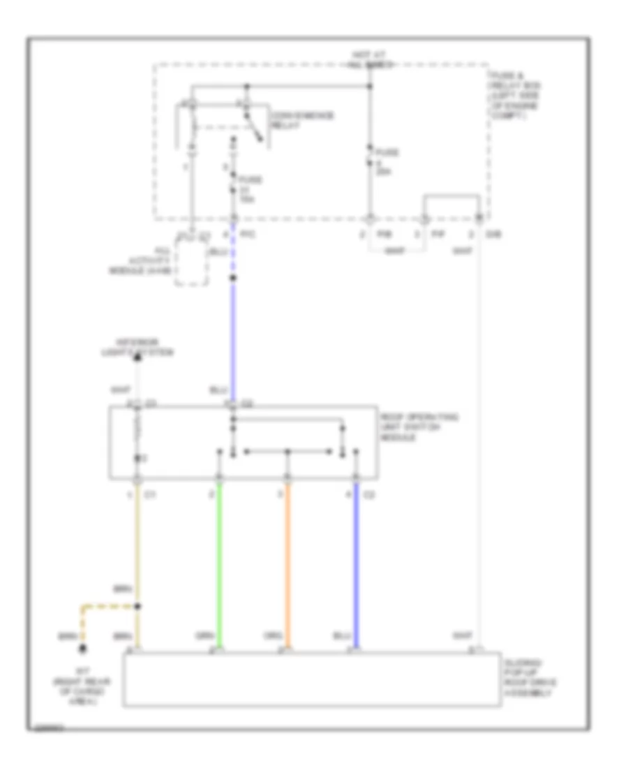
Электросхема привода люка или крыши для Mercedes-Benz ML500 2004
Электросхема привода люка или крыши для Mercedes-Benz ML500 2004 - Список элементов:
- All activity module (aam)
- Convenience relay
- D/b
- Fuse & relay box (left side of engine compt)
- Fuse 15a
- Fuse 20a
- Hot at all times
- Interior lights system
- P/b
- P/c
- P/f
- Roof operating unit switch module
- Sliding/ pop-up roof drive assembly
- W7 (right rear of cargo area)
ПРИВОД СТЕКЛОПОДЪЕМНИКОВ
Электросхема стеклоподъемников для Mercedes-Benz ML500 2004
Электросхема стеклоподъемников для Mercedes-Benz ML500 2004 - Список элементов:
- (below left side of dash)
- All activity module
- C/b
- Can h
- Can l
- Computer data lines
- Convenience relay
- Data link connector
- Diag
- Fuse & relay box (left side of engine compt)
- Fuse 15a
- Fuse 25a
- Hot at all times
- Hot in run or start
- Interior lights system
- Left front power window motor
- Left rear power window motor
- Lower control field control module (under center console)
- P/b
- P/c
- P/d
- Pnk
- Rear control field control module (under rear of center console)
- Red
- Right front footwell fuse & relay box (below right side of dash, behind kick panel)
- Right front power window motor
- Right rear power window motor
- W18 (below left front seat)
- X11/4
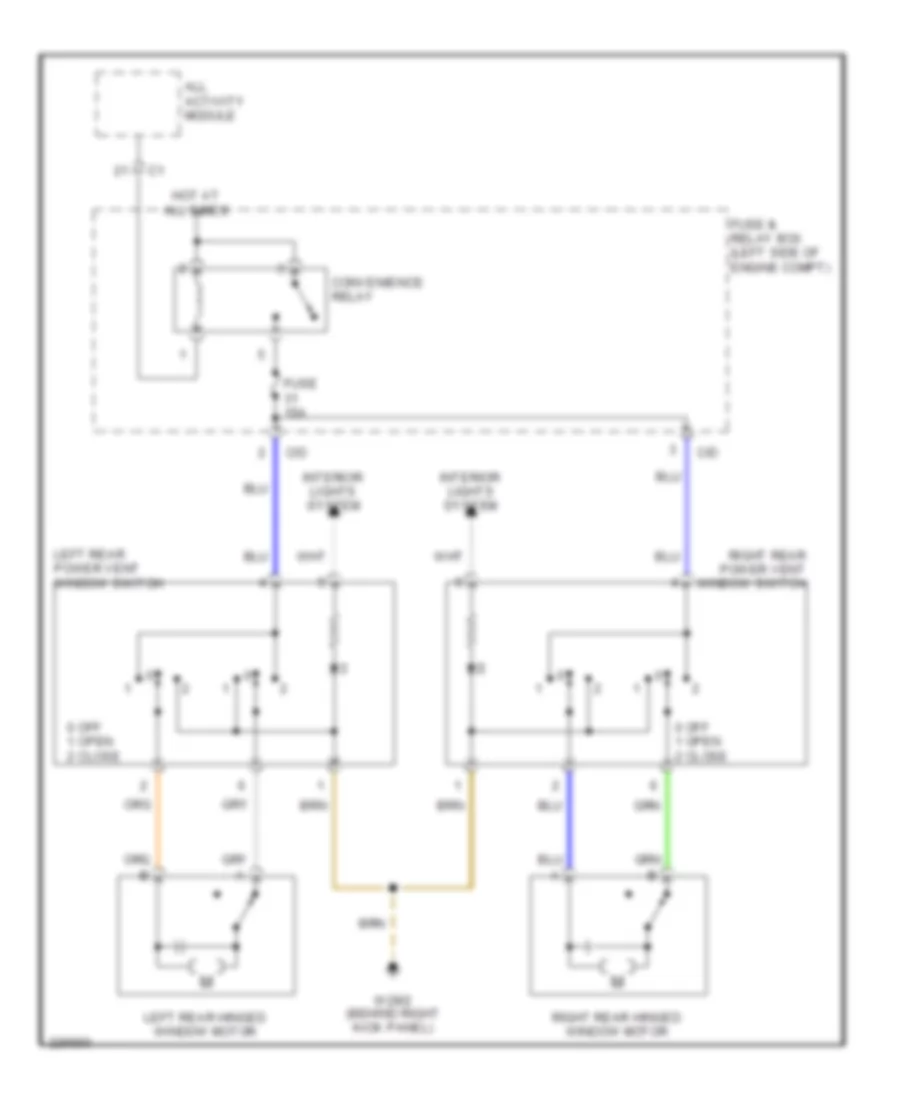
задний Windows Wiring Diagram четверти для Mercedes-Benz ML500 2004
задний Windows Wiring Diagram четверти для Mercedes-Benz ML500 2004 - Список элементов:
- 0 off 1 open 2 close
- All activity module
- C/d
- Convenience relay
- Fuse & relay box (left side of engine compt)
- Fuse 15a
- Hot at all times
- Interior lights system
- Left rear hinged window motor
- Left rear power vent window switch
- Right rear hinged window motor
- Right rear power vent window switch
- W29/2 (behind right kick panel)
Противоугонная система Сигнализация
Электросхема противоугонной сигнализации для Mercedes-Benz ML500 2004
Электросхема противоугонной сигнализации для Mercedes-Benz ML500 2004 - Список элементов:
- 15c
- A10
- A12
- Acc
- Ajar
- Alarm horn (left rear corner of engine compt)
- Alarm horn relay
- All activity module (left side of engine compt, in "e" box)
- Ata ind
- B11
- B12
- Battery
- C/d
- C/e
- Clock
- Computer data lines system
- Das control module
- Data 1
- Data 2
- Data 3
- Data link connector (below left side of dash)
- Diag
- Double combi- nation switch
- Engine hood switch
- Extended activity module (right front footwell)
- Exterior lights system
- Fuse & relay box (left side of engine compt, in "e" box)
- Fuse 20a
- Fuse 7.5a
- Glass break sensor
- Ignition key switch
- Ignition switch
- Immo
- Incline sensor
- Inhibit
- Ki 15
- Ki 15c
- Ki 30
- Ki 31
- Left front door lock motor
- Left rear door lock motor
- Lock
- Lower control field control module
- Mb-immobilizer control module (right side of steering column)
- Ml/a
- Mr/a
- Mr/d
- Nca
- Off
- P/d
- P/e
- Pnk
- Power distribution system
- Read
- Red
- Right front door lock motor
- Right kick panel)
- Right rear door lock motor
- Run
- Start
- Tailgate lock motor
- Temp ksk
- Temp off
- Trans- ponder coil
- Trip computer control module
- Trunk lid micro switch
- W16/4 (right rear of eng compt)
- W18 (below left front seat)
- W19 (below right front seat)
- W29/2 (behind
- W8 (center of tailgate)
- W9 (behind left headlamp)
- Write
СИСТЕМА АНТИБЛОКИРОВОЧНОЙ ТОРМОЗНОЙ СИСТЕМЫ ABS
Электросхема антиблокировочной тормозной системы АБС (ABS) (1 из 2) для Mercedes-Benz ML500 2004
Электросхема антиблокировочной тормозной системы АБС (ABS) (1 из 2) для Mercedes-Benz ML500 2004 - Список элементов:
- A11
- Abs mil
- B10
- Bas/esp mil
- Bav 12v
- Bav a
- Bbv
- Bla
- Brake booster (bas)
- Brake fluid level switch (in brake fluid reservoir)
- Brake pad wear indicator
- Can h
- Can l
- Close
- Clu m
- Clu12v
- Computer data lines system
- Df vl0
- Df vl1
- Dfa hl
- Dfa hr
- Dfa vl
- Dfa vr
- Dfhl0
- Dfhl1
- Dfhr0
- Dfhr1
- Dg1 m
- Dg1 s
- Dg1+5v
- Diag
- Esp brake pressure sensor 1 (in left rear of engine compt)
- Esp off
- Ets mil
- Ets warning lamp
- Fuse & relay box (left side of engine compt)
- Fuse 15a
- Fuse 40a
- Has
- Headlamp range adjustment control module (behind driver's side of dash)
- Hot at all times
- Instrument cluster
- Left front brake pad wear sensor
- Left front vehicle speed sensor
- Left rear brake pad wear sensor
- Ls a
- Lws
- Membrane travel sensor
- Ml/a
- Mp 5v
- Mp m
- Mp s
- Nca
- Open
- Pnk
- Pts control module (behind center of dash)
- Red
- Release switch
- Right front brake pad wear sensor (ml500)
- Right front footwell fuse & relay box (below right side of dash, behind kick panel)
- Right front vehicle speed sensor
- Right rear brake pad wear sensor (ml500)
- Solenoid valve
- Traction systems control module (left front of eng compt)
- Ubatt1
- Ubatt2
- W16/4 (right rear of engine compt)
- W9 (behind left headlight)
Электросхема антиблокировочной тормозной системы АБС (ABS) (2 из 2) для Mercedes-Benz ML500 2004
Электросхема антиблокировочной тормозной системы АБС (ABS) (2 из 2) для Mercedes-Benz ML500 2004 - Список элементов:
- Abs left
- Abs right
- All activity module (aam) (in "e" box)
- C/b
- C/c
- C/f
- C/h
- Circuit 15 relay
- Computer data lines system
- Data link connector (dlc) (below left side of dash)
- Emergency call system control module (under right front seat)
- Esp off switch
- Esp stop lamp suppression relay
- Exterior lights system
- Fuse & relay box
- Fuse & relay box (left side of engine compt)
- Fuse 10a
- Fuse 15a
- Gal
- Hot at all times
- Interior lights system
- Left rear vehicle speed sensor
- Ml500
- Mr/e
- Nca
- P/b
- P/c
- Parking brake switch (on parking brake support bracket)
- Pnk
- Radio or radio navigation unit
- Red
- Right rear vehicle speed sensor
- Rotational speed & lateral acceleration sensor (below center console, behind shift assembly)
- Signal
- Steering angle sensor (below driver's side of dash)
- W29/2 (behind right kick panel)
СИСТЕМА КОНДИЦИОНЕРА
Электросхема кондиционера (1 из 2) для Mercedes-Benz ML500 2004
Электросхема кондиционера (1 из 2) для Mercedes-Benz ML500 2004 - Список элементов:
- (behind right kick panel) w29/2
- (below right front seat)
- A/c compressor
- Aac pushbutton control module (behind center of dash)
- C/c
- C/g
- Can h
- Can l
- Center nozzle air stream temperature sensor (below center of dash)
- Computer data lines
- Coolant circulation pump (right rear of engine compt)
- Data link connector
- Defogger system
- Evaporator temperature sensor (behind right side of dash, in evaporator)
- Front footwell airstream temperature sensor (below center of dash)
- Fuse & relay box (in left side of engine compartment, in "e" box)
- Fuse 15a
- Fuse 20a
- Fuse 40a
- Heating systems recirculation unit (below right side of dash)
- Hot at all times
- Hot in run or start
- Interior lights system
- Module box blower motor (in left side of engine compartment)
- Mr/e
- Nca
- Pnk
- Rear air distribution flap actuator motor (below rear center console)
- Rear airstream temperature sensor (below rear of center console)
- Rear blower motor (below rear center console)
- Rear ventilation electronic blower controller (below center console)
- Red
- Refrigerant pressure & temperature sensor (left front of engine compt)
- Right front footwell fuse & relay box (behind right kick panel)
- Sun sensor (top of dash)
- W16/4 (right side of firewall)
- W19
- W29/2 (behind right kick panel)
Электросхема кондиционера (2 из 2) для Mercedes-Benz ML500 2004
Электросхема кондиционера (2 из 2) для Mercedes-Benz ML500 2004 - Список элементов:
- A12
- All activity module (aam)
- B12
- Blending air flap actuator motor (below center of dash)
- Can h
- Can l
- Center outlet flap actuator motor (behind right side of dash)
- Computer data lines system
- Defroster vent flap actuator motor (below center of dash)
- Engine control module (me-sfi) (in left side of engine compartment, in "e" box)
- Engine cooling fan stage 1 relay (ml320, ml350)
- Extended activity module (right front footwell)
- Footwell flap actuator motor (below center of dash)
- Fresh & recirculated air flap actuator motor (behind right side of dash)
- Fuse & relay box (in left side of engine compartment, in "e" box)
- Fuse 40a
- Hot at all times
- Left auxiliary fan (ml320, ml350)
- Lower control field control module (at shifter)
- M4x1
- Ml/b
- Nca
- Rear shutoff flap actuator motor (below center of dash)
- Right auxiliary fan (ml320, ml350)
- W9 (behind left headlamp)
СИСТЕМА КРУИЗКОНТРОЛЯ
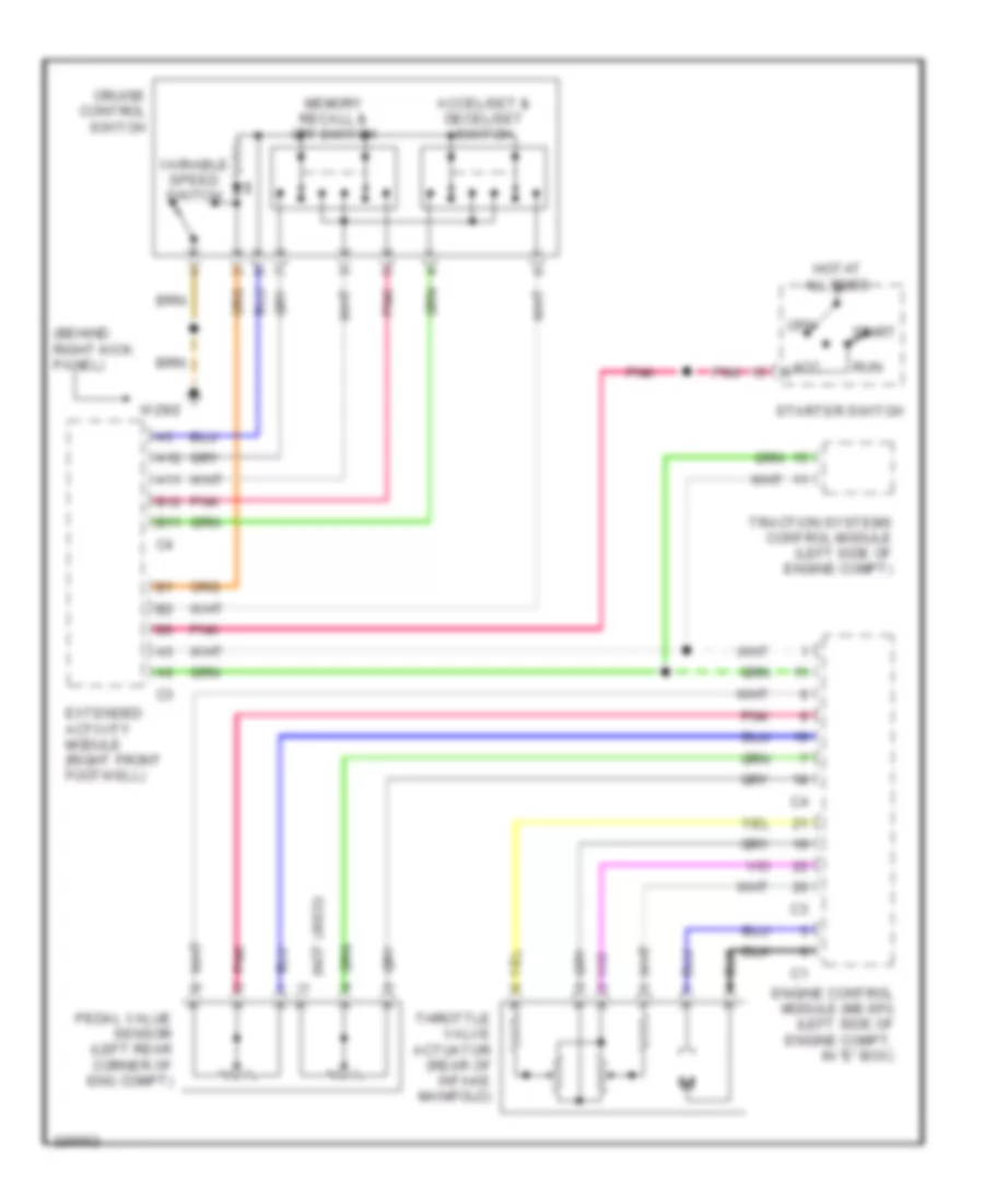
Электросхема системы круизконтроля для Mercedes-Benz ML500 2004
Электросхема системы круизконтроля для Mercedes-Benz ML500 2004 - Список элементов:
- (behind right kick panel)
- (not used)
- A11
- A12
- Acc
- Accel/set & decel/set switch
- B11
- B12
- Cruise control switch
- Engine control module (me-sfi) (left side of engine compt, in "e" box)
- Extended activity module (right front footwell)
- Hot at all times
- Memory recall & off switch
- Off
- Pedal value sensor (left rear corner of eng compt)
- Pnk
- Run
- Start
- Starter switch
- Throttle valve actuator (rear of intake manifold)
- Traction systems control module (left side of engine compt)
- Variable speed switch
- W29/2
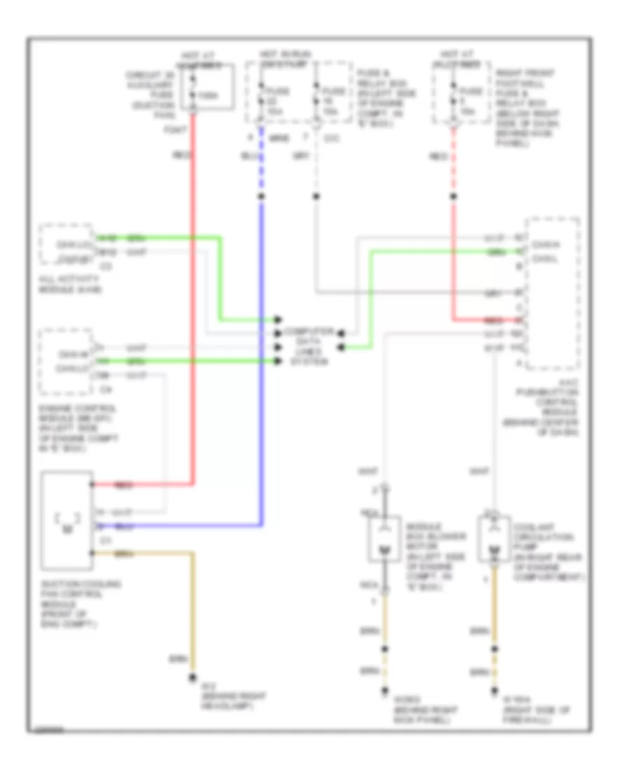
СИСТЕМА ОХЛАЖДЕНИЯ
Электросхема системы охлаждения для Mercedes-Benz ML500 2004
Электросхема системы охлаждения для Mercedes-Benz ML500 2004 - Список элементов:
- 100a
- A12
- Aac pushbutton control module (behind center of dash)
- All activity module (aam)
- B12
- C/c
- Can h
- Can hi
- Can l
- Can lo
- Circuit 30 auxiliary fuse (suction fan)
- Computer data lines system
- Coolant circulation pump (in right rear of engine compartment)
- Engine control module (me-sfi) (in left side of engine compt in "e" box)
- F24/7
- Fuse & relay box (in left side of engine compt, in "e" box)
- Fuse 15a
- Hot at all times
- Hot in run or start
- Module box blower motor (in left side of engine compt, in "e" box)
- Mr/e
- Nca
- Red
- Right front footwell fuse & relay box (below right side of dash, behind kick panel)
- Suction cooling fan control module (front of eng compt)
- W16/4 (right side of firewall)
- W2 (behind right headlamp)
- W29/2 (behind right kick panel)
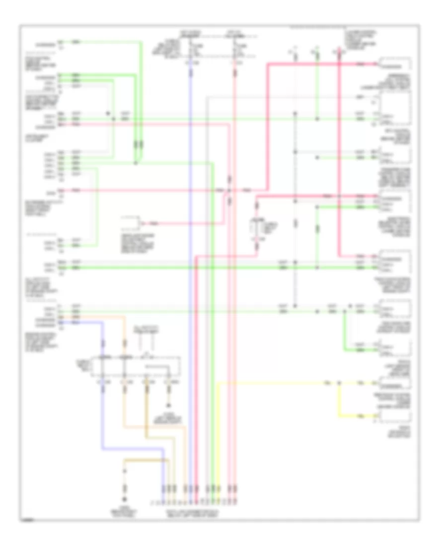
СИСТЕМА ПЕРЕДАЧИ ДАННЫХ
Электросхема линии передачи данных CAN для Mercedes-Benz ML500 2004
Электросхема линии передачи данных CAN для Mercedes-Benz ML500 2004 - Список элементов:
- A12
- Aac pushbutton control module (behind center of dash)
- All activity module (aam)
- All activity module (aam) (in left side of engine compt, in "e" box)
- B10
- B11
- B12
- C/b
- C/c
- C/e
- C2 pnk
- Can h
- Can l
- Data link connector (dlc) (below left side of dash)
- Diag
- Diagnosis
- Electronic selector lever control module (under center console)
- Emergency call system control module (under right front seat)
- Engine control module (me-sfi) (in left side of engine compt, in "e" box)
- Etc control module (behind center of dash)
- Extended activity module (eam) (right front footwell)
- Fuse & relay box
- Fuse & relay box (left side of eng compt, in "e" box)
- Fuse 10a
- Fuse 15a
- Headlamp range adjustment control module (behind driver's side of dash)
- Hot at all times
- Hot in run or start
- Instrument cluster
- Lower control field control module (under center console)
- Mr/d
- P/b
- P/d
- Pnk
- Pts control module (behind center of dash)
- Radio (or radio & navigation)
- Rain & light sensor (front of headliner)
- Red
- Restraint system control module (under center console)
- Traction systems control module (left front of engine compt)
- Transfer case control module (below center console, behind shift assembly)
- Trip computer control module (in front of roof)
- W16/5 (left rear of engine compt)
- W29/2 (behind right kick panel)
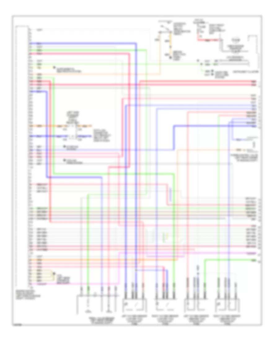
СИСТЕМА УПРАВЛЕНИЯ ДВИГАТЕЛЯ
Электросхема системы управления двигателем (1 из 3) для Mercedes-Benz ML500 2004
Электросхема системы управления двигателем (1 из 3) для Mercedes-Benz ML500 2004 - Список элементов:
- (behind right kick panel) w29/2
- (left side of engine compt) fuse & relay box
- A11
- B10
- C/b
- C/e
- Check engine indicator
- Computer data lines system
- Cooling fans system
- Data link connector (dtc readout) (below left side of dash)
- Engine control module (me-sfi) (left side of engine compt, in e box)
- Fuse 15a
- Hot at all times
- Instrument cluster
- Kickdown switch (below accelerator pedal)
- Left oxygen sensor 1 (before twc) (in exhaust pipe)
- Left oxygen sensor 2 (after twc) (in exhaust pipe)
- Low engine oil indicator
- Nca
- P/b
- P/d
- Pedal value sensor (left rear corner of engine compt)
- Pnk
- Purge control valve (left rear corner of engine compt)
- Red
- Right front footwell fuse & relay box
- Right oxygen sensor 1 (before twc) (in exhaust pipe)
- Right oxygen sensor 2 (after twc) (in exhaust pipe)
- Starting system
- W16 (left rear corner of eng compt)
Электросхема системы управления двигателем (2 из 3) для Mercedes-Benz ML500 2004
Электросхема системы управления двигателем (2 из 3) для Mercedes-Benz ML500 2004 - Список элементов:
- (right front of engine) air pump switchover valve
- (top center front of engine) shifting induction pipe switchover valve
- (top rear of engine) egr valve pressure transducer
- Activated charcoal canister shut-off valve (under rear of vehicle, above spare wheel)
- Battery
- C/d
- Camshaft hall-effect sensor (right front of engine)
- Crankshaft position sensor (left rear of engine)
- Electric air pump (center front of engine)
- Fuel pump
- Fuel pump relay
- Fuel pump with fuel level sensor (top of fuel tank)
- Fuel tank emissions monitoring pressure sensor (behind trim on fuel filler pipe)
- Fuse & relay box (left side of engine compt)
- Fuse 15a
- Fuse 20a
- Fuse 40a
- Hot at all times
- Hot film maf sensor (center rear of intake manifold)
- Hot in run or start
- M/a
- Mr/c
- Mr/d
- Mr/e
- P/d
- P/e
- Pnk
- Red
- Right front footwell fuse & relay box
- Secondary air injection pump relay
- Throttle valve control element (center rear of engine)
- W11/3 (front of engine)
- W6 (left rear cargo area)
Электросхема системы управления двигателем (3 из 3) для Mercedes-Benz ML500 2004
Электросхема системы управления двигателем (3 из 3) для Mercedes-Benz ML500 2004 - Список элементов:
- (center front of engine) ect sensor
- (front center of engine) w11/3
- (lower right front of engine) oil sensor
- (right front of engine) pressure sensor
- Engine control module (me-sfi) (left side of engine compt, in e box)
- Fuel injectors
- Fuse & relay box (left side of engine compt)
- Fuse 15a
- Hot in run or start
- Ign coil
- Ign coil coil
- Knock sensor 1 (right side of engine)
- Knock sensor 2 (left side of engine)
- M/a
- M/c
- Noise sup- pressors
- Pnk
- Red
- Shield
- To spark plugs
Система Фар
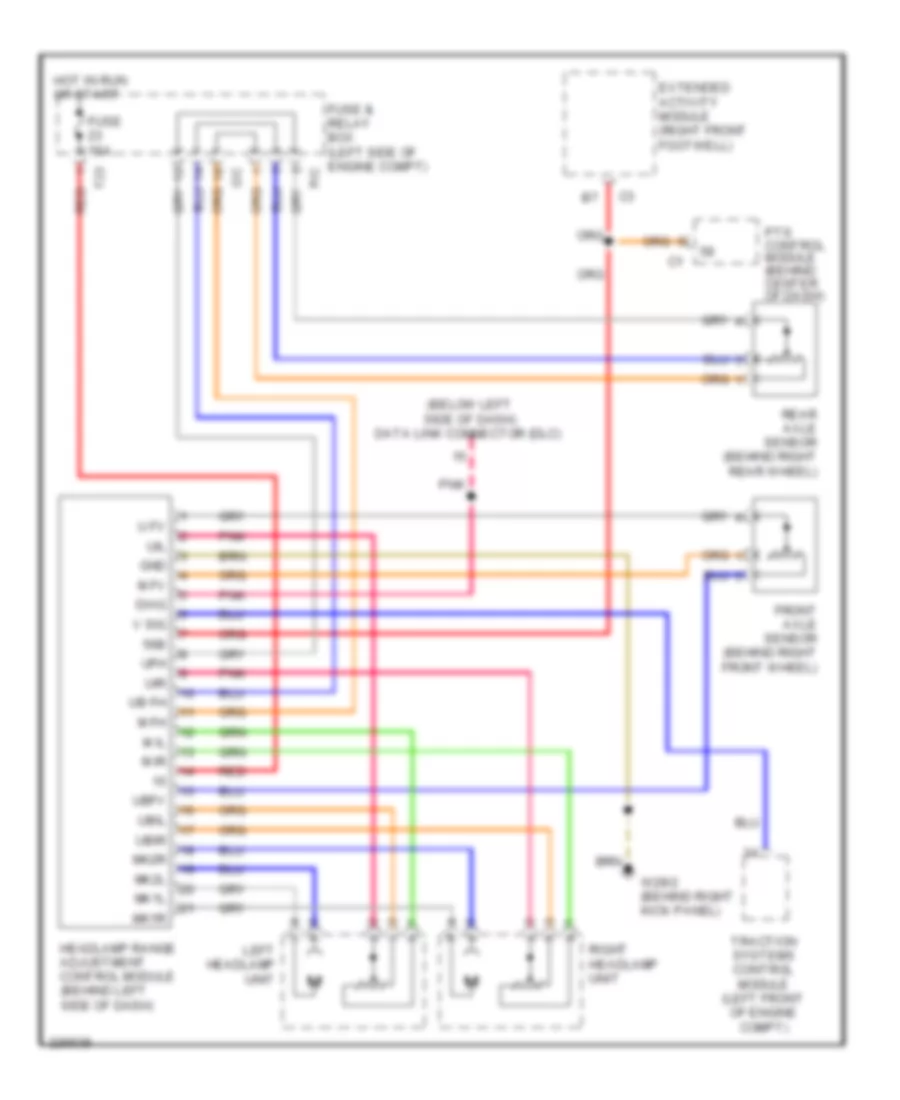
Электросхема корректора фар для Mercedes-Benz ML500 2004
Электросхема корректора фар для Mercedes-Benz ML500 2004 - Список элементов:
- (below left side of dash) data link connector (dlc)
- 56b
- Diag
- Extended activity module (right front footwell)
- F23 red
- Front axle sensor (behind right front wheel)
- Fuse & relay box (left side of engine compt)
- Fuse 15a
- Gnd
- Headlamp range adjustment control module (behind left side of dash)
- Hot in run or start
- Left headlamp unit
- M fh
- M fv
- M il
- M ir
- Mk1l
- Mk1r
- Mk2l
- Mk2r
- Pnk
- Pts control module (behind center of dash)
- Rear axle sensor (behind right rear wheel)
- Red
- Right headlamp unit
- Traction systems control module (left front of engine compt)
- U fv
- Ub fh
- Ubfv
- Ubil
- Ubir
- Ufh
- Uil
- Uir
- V sig
- W29/2 (behind right kick panel)
Электросхема фар, С Ксеноновые лампы (1 из 2) для Mercedes-Benz ML500 2004
Электросхема фар, С Ксеноновые лампы (1 из 2) для Mercedes-Benz ML500 2004 - Список элементов:
- (left side of engine compartment) all activity module
- 56a
- 56d
- 58a
- 58d
- 58l
- 58r
- A11
- A13
- Accy
- All activity module (left side of eng compt)
- Auto
- B10
- C/b
- C/d
- C/e
- C/f
- Combination switch
- Extended activity module (right front footwell)
- Exterior lights system
- Flash
- Fuse & relay box (left side of engine compt)
- Fuse 7.5a
- Head
- Headlamp flasher/ high beam switch
- High
- Hot at all times
- Instrument cluster
- Light switch
- Low
- Ml/a
- Mr/d
- Mr/e
- Off
- P/b
- P/e
- P30
- Park
- Pnk
- Power distribution system
- Run
- Standing
- Start
- Starter switch
- To left headlamp unit (diagram 2 of 2)
- To right headlamp unit (diagram 2 of 2)
- Turn signal switch
Электросхема фар, С Ксеноновые лампы (2 из 2) для Mercedes-Benz ML500 2004
Электросхема фар, С Ксеноновые лампы (2 из 2) для Mercedes-Benz ML500 2004 - Список элементов:
- A12
- All activity module (left side of engine compt)
- B10
- B12
- C/e
- Computer data lines system
- Double combination switch
- Foglamp indicator
- From extended activity module (diagram 1 of 2)
- Front foglamp relay
- Front/rear foglamp switch
- Fuse & relay box (left side of engine compt)
- Fuse 15a
- Fuse 7.5a
- High
- High beam indicator
- Hot at all times
- Illum- ination
- Instrument cluster
- Interior lights system
- Left front foglamp
- Left headlamp unit
- Left taillamp unit
- Low
- Ml/c
- P/e
- Pnk
- Rear foglamp
- Rear foglamp indicator lamp
- Rear foglamp relay
- Red
- Relay
- Right front foglamp
- Right front footwell fuse & relay box (below right side of dash, behind kick panel)
- Right headlamp unit
- W2 (behind right headlamp)
- W29/2 (behind right kick panel)
- W6 (left rear of cargo area, behind trim)
- W9 (behind left headlamp)
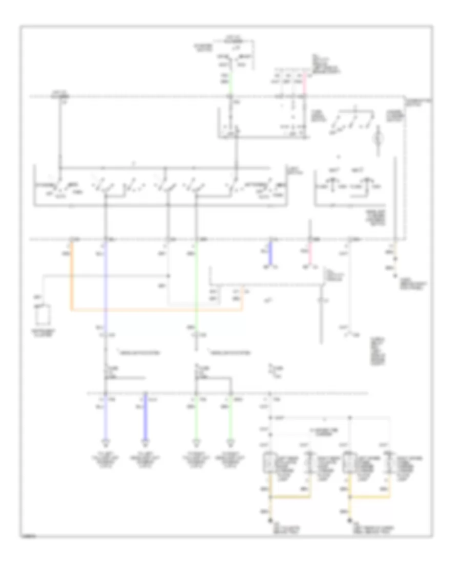
Электросхема фар, без Ксеноновые лампы (1 из 2) для Mercedes-Benz ML500 2004
Электросхема фар, без Ксеноновые лампы (1 из 2) для Mercedes-Benz ML500 2004 - Список элементов:
- (left side of engine compartment) all activity module
- 56a
- 56d
- 58a
- 58d
- 58l
- 58r
- A11
- A13
- Accy
- All activity module (left side of eng compt)
- Auto
- B10
- C/b
- C/d
- C/e
- C/f
- Combination switch
- Extended activity module (right front footwell)
- Exterior lights system
- Flash
- Fuse & relay box (left side of engine compt)
- Fuse 7.5a
- Head
- Headlamp flasher/ high beam switch
- High
- Hot at all times
- Instrument cluster
- Light switch
- Low
- Ml/a
- Mr/d
- Mr/e
- Off
- P/b
- P/e
- P30
- Park
- Pnk
- Power distribution system
- Run
- Standing
- Start
- Starter switch
- To left headlamp unit (diagram 2 of 2)
- To right headlamp unit (diagram 2 of 2)
- Turn signal switch
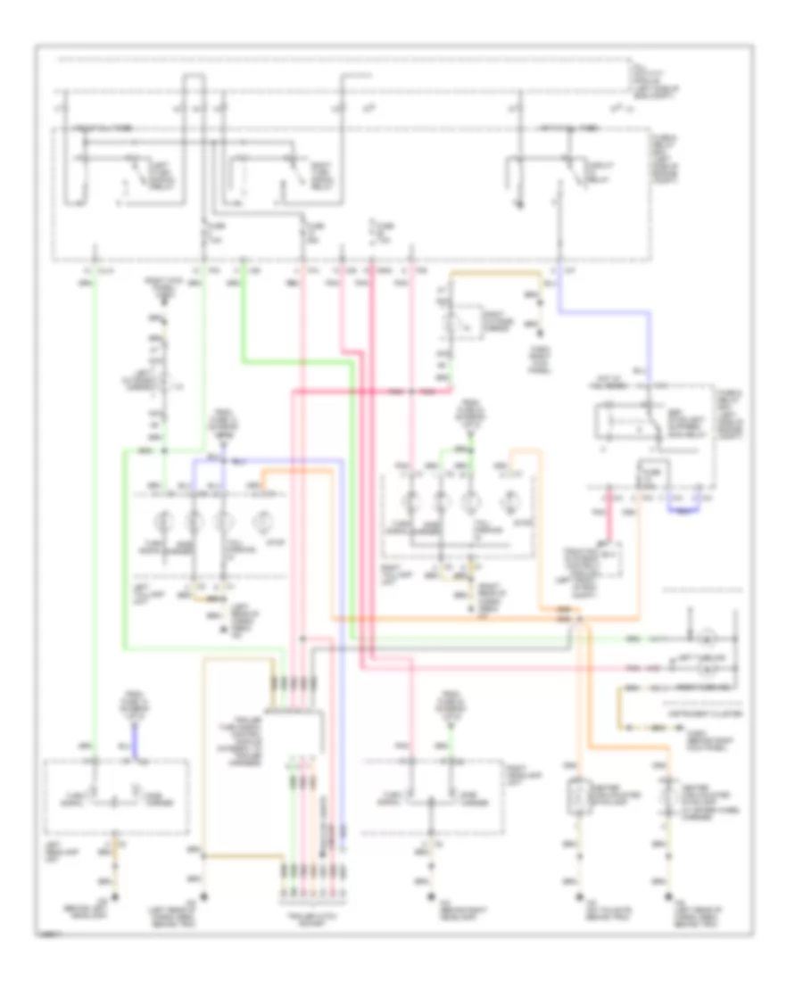
Электросхема фар, без Ксеноновые лампы (2 из 2) для Mercedes-Benz ML500 2004
Электросхема фар, без Ксеноновые лампы (2 из 2) для Mercedes-Benz ML500 2004 - Список элементов:
- A12
- All activity module (left side of engine compt)
- B10
- B12
- C/e
- Computer data lines system
- Double combination switch
- Foglamp indicator
- From extended activity module (diagram 1 of 2)
- Front foglamp relay
- Front/rear foglamp switch
- Fuse & relay box (left side of engine compt)
- Fuse 15a
- Fuse 7.5a
- High beam
- High beam indicator
- Hot at all times
- Illum- ination
- Instrument cluster
- Interior lights system
- Left front foglamp
- Left headlamp unit
- Left taillamp unit
- Low beam
- Ml/c
- P/e
- Pnk
- Rear foglamp
- Rear foglamp indicator lamp
- Rear foglamp relay
- Red
- Relay
- Right front foglamp
- Right front footwell fuse & relay box (below right side of dash, behind kick panel)
- Right headlamp unit
- W2 (behind right headlamp)
- W29/2 (behind right kick panel)
- W6 (left rear of cargo area, behind trim)
- W9 (behind left headlamp)
СИСТЕМЫ ПАМЯТИ
Электросхема памяти водительского сиденья для Mercedes-Benz ML500 2004
Электросхема памяти водительского сиденья для Mercedes-Benz ML500 2004 - Список элементов:
- (behind right kick panel) w29/2
- A10
- Aft
- Backrest aft
- Backrest fore
- Backrest fore/aft motor
- C10
- C11
- Extended activity module (right front footwell)
- Fore
- Fore/aft motor
- Front lower
- Front raise
- Front raise/ lower motor
- Fuse & relay box (left side of engine compt, in "e" box)
- Fuse 25a
- Fuse 35a
- Hot w/ circuit 15 relay energized
- Hot w/ relay 1 energized
- Interior lights system
- Left front backrest heater element
- Left front electric seat adjustment control module (under left front seat)
- Left front electric seat adjustment switch
- Left front seat cushion heater element
- Left front seat heater switch
- Lower control field control module (under center console)
- Memory 1
- Memory 2
- Memory 3
- Memory store
- Nca
- P/b
- Pnk
- Rear lower
- Rear raise
- Rear raise/ lower motor
- Right front footwell fuse & relay module
- W18 (below left front seat)
Электросхема памяти пассажирского сиденья для Mercedes-Benz ML500 2004
Электросхема памяти пассажирского сиденья для Mercedes-Benz ML500 2004 - Список элементов:
- (behind right kick panel) w29/2
- Aft
- Backrest aft
- Backrest fore
- Backrest fore/aft motor
- C10
- C11
- Extended activity module (right front footwell)
- Fore
- Fore/aft motor
- Front lower
- Front raise
- Front raise/ lower motor
- Fuse & relay box
- Fuse 25a
- Fuse 35a
- Hot w/ circuit 15 relay energized
- Hot w/ relay 1 energized
- Interior lights system
- Lower control field control module (under center console)
- Memory 1
- Memory 2
- Memory 3
- Memory store
- Nca
- P/b
- Pnk
- Rear lower
- Rear raise
- Rear raise/ lower motor
- Right front backrest heater element
- Right front electric seat adjustment control module (under right front seat)
- Right front electric seat adjustment switch
- Right front footwell fuse & relay module
- Right front seat cushion heater element
- Right front seat heater switch
- W19 (below right front seat)
СИСТЕМЫ СИДЕНИЙ
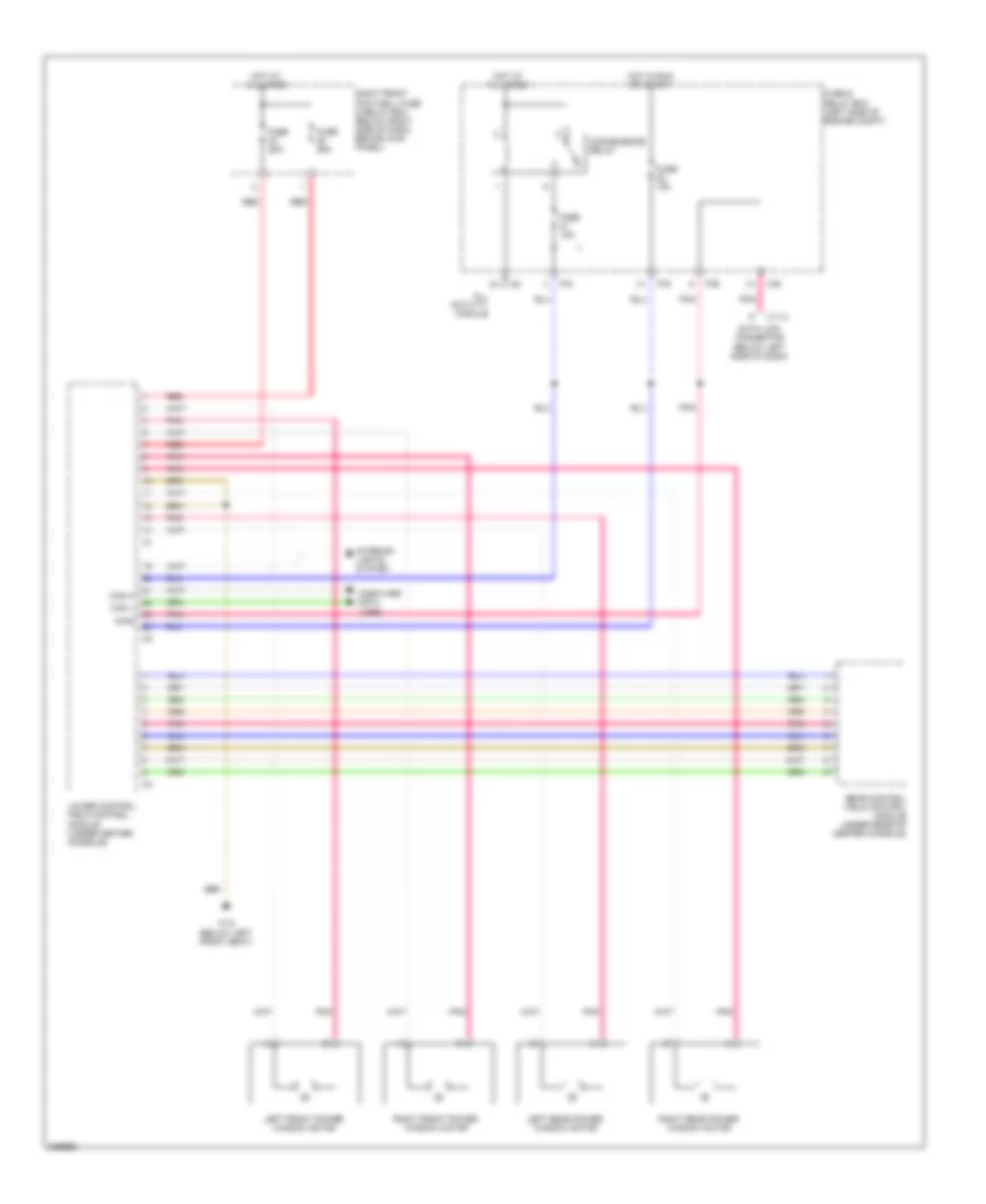
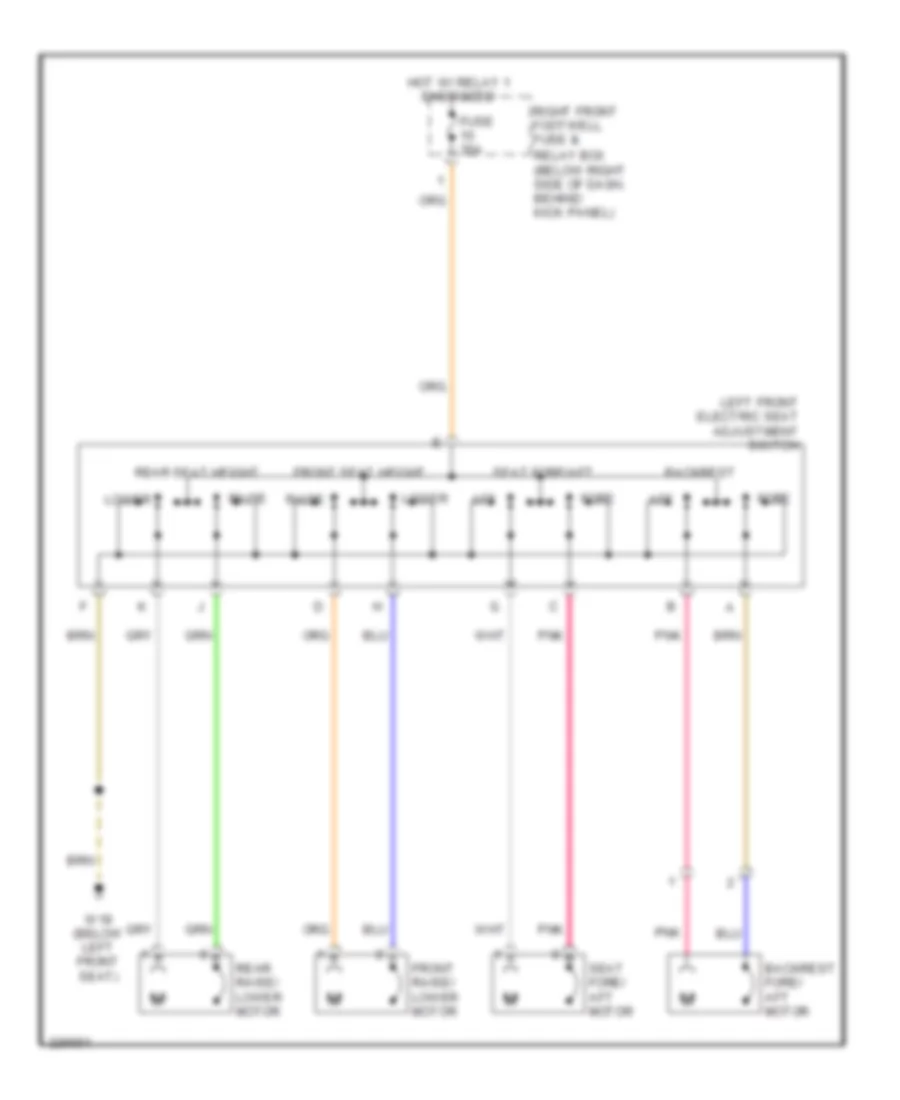
Электросхема привода водительского сиденья для Mercedes-Benz ML500 2004
Электросхема привода водительского сиденья для Mercedes-Benz ML500 2004 - Список элементов:
- Aft
- Backrest
- Backrest fore/ aft motor
- Fore
- Front raise/ lower motor
- Front seat height
- Fuse 35a
- Hot w/ relay 1 energized
- Left front electric seat adjustment switch
- Lower
- Pnk
- Raise
- Rear raise/ lower motor
- Rear seat height
- Relay box (below right side of dash, behind kick panel)
- Right front footwell fuse &
- Seat fore/ aft motor
- Seat fore/aft
- W18 (below left front seat)
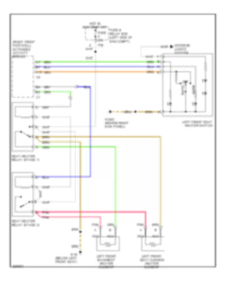
водитель "s схема сиденья с подогревом для Mercedes-Benz ML500 2004
водитель "s схема сиденья с подогревом для Mercedes-Benz ML500 2004 - Список элементов:
- (right front footwell) extended activity module
- A10
- Eng compt)
- Fuse & relay box (left side of
- Fuse 25a
- Hot in run or start
- Interior lights system
- Left front backrest heater element
- Left front seat cushion heater element
- Left front seat heater switch
- Nca
- Norm
- Off
- P/b
- Pnk
- Rapid
- Seat heater relay (stage 1)
- Seat heater relay (stage 2)
- W18 (below left front seat)
- W29/2 (behind right kick panel)
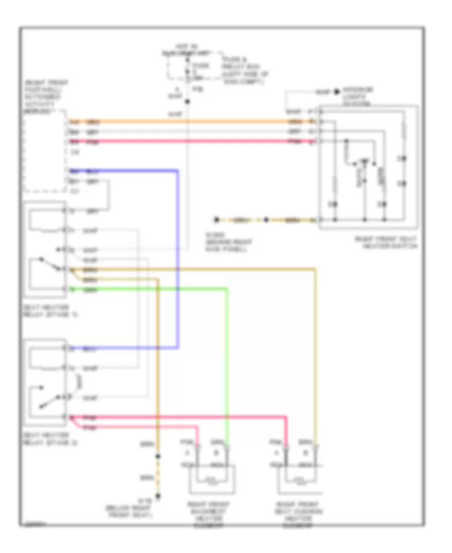
Электросхема подогрева пассажирского сиденья для Mercedes-Benz ML500 2004
Электросхема подогрева пассажирского сиденья для Mercedes-Benz ML500 2004 - Список элементов:
- (right front footwell) extended activity module
- Eng compt)
- Fuse & relay box (left side of
- Fuse 25a
- Hot in run or start
- Interior lights system
- Nca
- Norm
- Off
- P/b
- Pnk
- Pnk e
- Rapid
- Right front backrest heater element
- Right front seat cushion heater element
- Right front seat heater switch
- Seat heater relay (stage 1)
- Seat heater relay (stage 2)
- W19 (below right front seat)
- W29/2 (behind right kick panel)
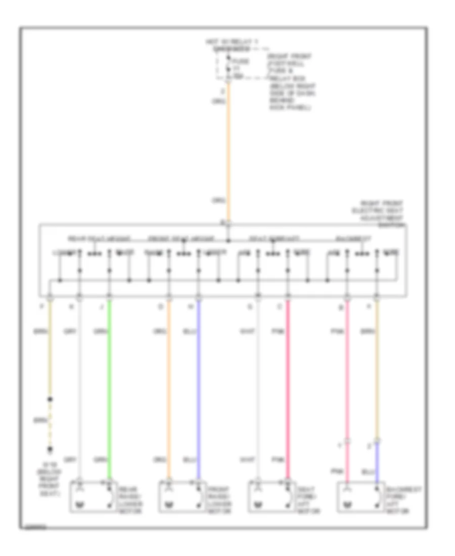
Электросхема привода пассажирского сиденья для Mercedes-Benz ML500 2004
Электросхема привода пассажирского сиденья для Mercedes-Benz ML500 2004 - Список элементов:
- Aft
- Backrest
- Backrest fore/ aft motor
- Fore
- Front raise/ lower motor
- Front seat height
- Fuse 35a
- Hot w/ relay 1 energized
- Lower
- Pnk
- Raise
- Rear raise/ lower motor
- Rear seat height
- Relay box (below right side of dash, behind kick panel)
- Right front electric seat adjustment switch
- Right front footwell fuse &
- Seat fore/ aft motor
- Seat fore/aft
- W19 (below right front seat)
Стартер Генератор
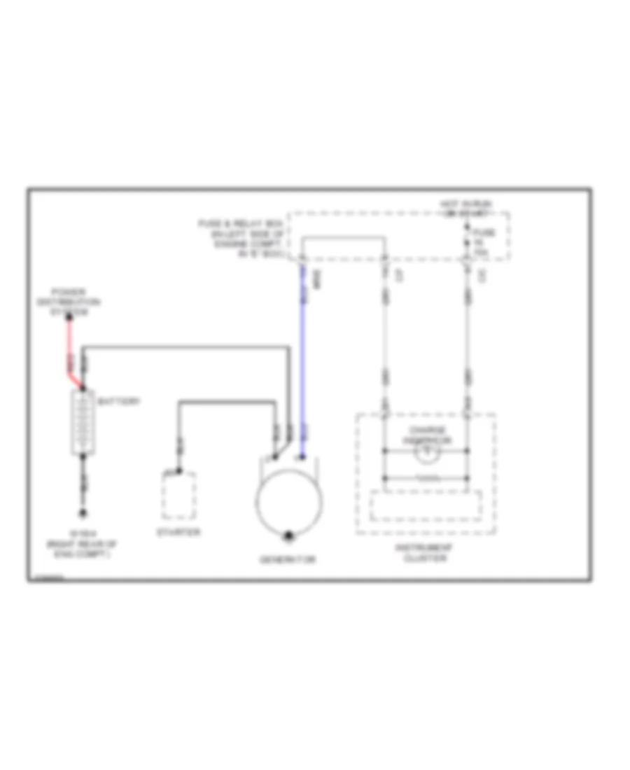
Электросхема Генератора для Mercedes-Benz ML500 2004
Электросхема Генератора для Mercedes-Benz ML500 2004 - Список элементов:
- Battery
- C/c
- C/f
- Charge indicator
- Fuse & relay box (in left side of engine compt, in "e" box)
- Fuse 15a
- Generator
- Hot in run or start
- Instrument cluster
- Mr/e
- Power distribution system
- Red
- Starter
- W16/4 (right rear of eng compt)
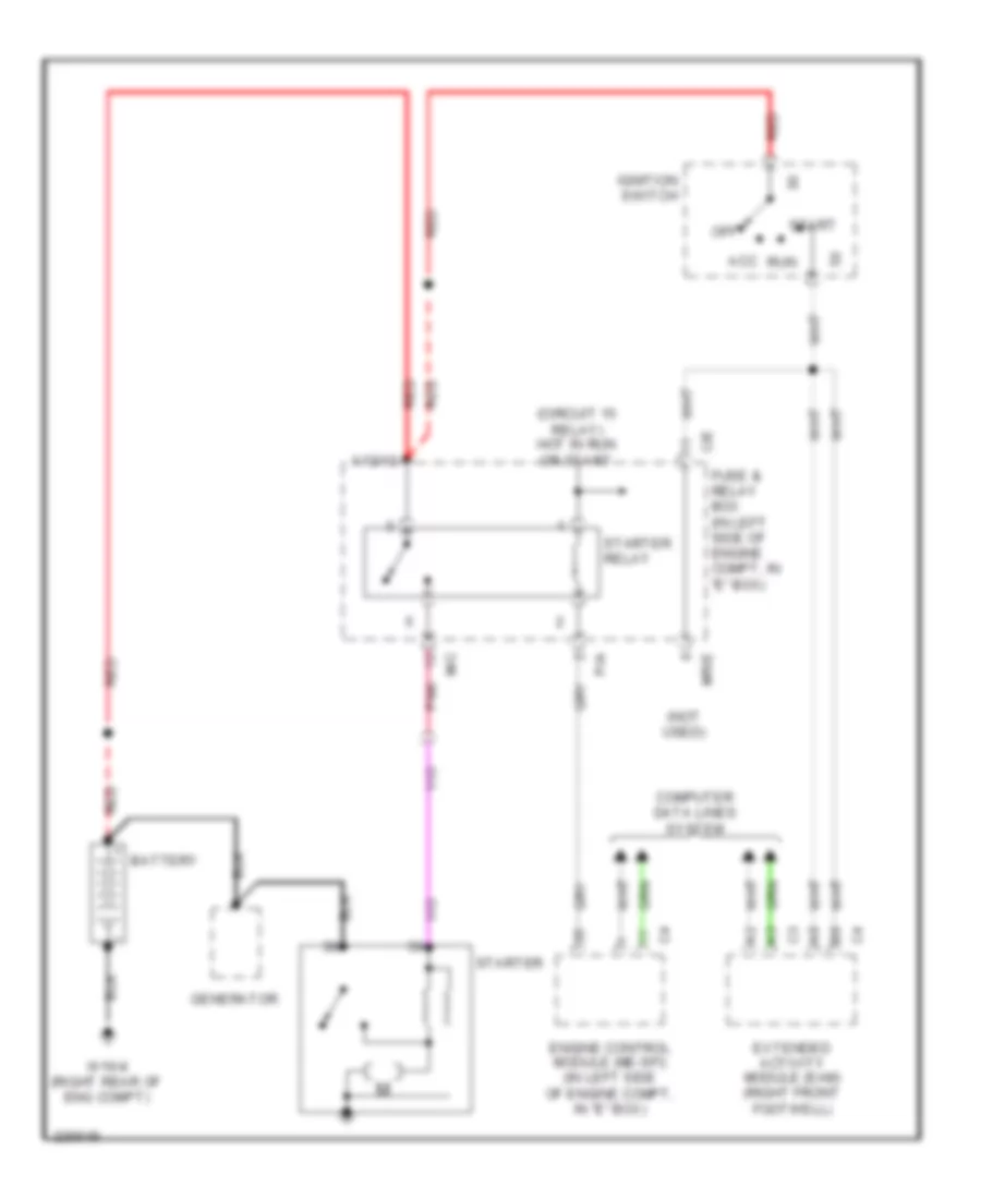
Электросхема стартера для Mercedes-Benz ML500 2004
Электросхема стартера для Mercedes-Benz ML500 2004 - Список элементов:
- (circuit 15 relay) hot in run or start
- (not used)
- Acc
- Battery
- C/e
- Computer data lines system
- Engine control module (me-sfi) (in left side of engine compt, in "e" box)
- Extended activity module (eam) (right front footwell)
- Fuse & relay box (in left side of engine compt, in "e" box)
- Generator
- Ignition switch
- M/c
- Mr/e
- Off
- P/a
- Pnk
- Red
- Run
- Start
- Starter
- Starter relay
- W16/4 (right rear of eng compt)
- X12/12
Стеклоочистители и Стеклоомыватели Дворники
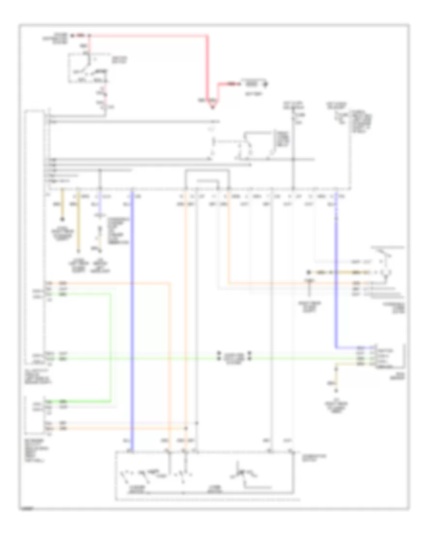
Электросхема передних стеклоочистителей дворников и омывателя лобового стекла для Mercedes-Benz ML500 2004
Электросхема передних стеклоочистителей дворников и омывателя лобового стекла для Mercedes-Benz ML500 2004 - Список элементов:
- (right rear of eng compt)
- A12
- Acc
- All activity module (left side of engine compt)
- B10
- B12
- Battery
- C/b
- C/d
- C/f
- Can h
- Can l
- Combination switch
- Computer data lines system
- Extended activity module (eam) (right front footwell)
- Front wiper motor relay
- Fuse & relay box (left side of engine compt, in "e" box)
- Fuse 15a
- Fuse 30a
- Ground
- Hot in off, acc or run
- Hot in run or start
- Ignition
- Ignition switch
- Int
- Ml/a
- Mr/a
- Mr/d
- Mr/e
- Off
- P/d
- Pnk
- Power distribution system
- Rain sensor
- Red
- Run
- Start
- W16/4
- W16/4 (right rear of engine compt)
- W16/5 (left rear of eng compt)
- W7 (right rear of cargo area)
- W9 (behind left headlamp)
- Wash
- Washer switch
- Windshield washer pump (on washer fluid reservoir)
- Windshield wiper motor
- Wipe
- Wiper switch
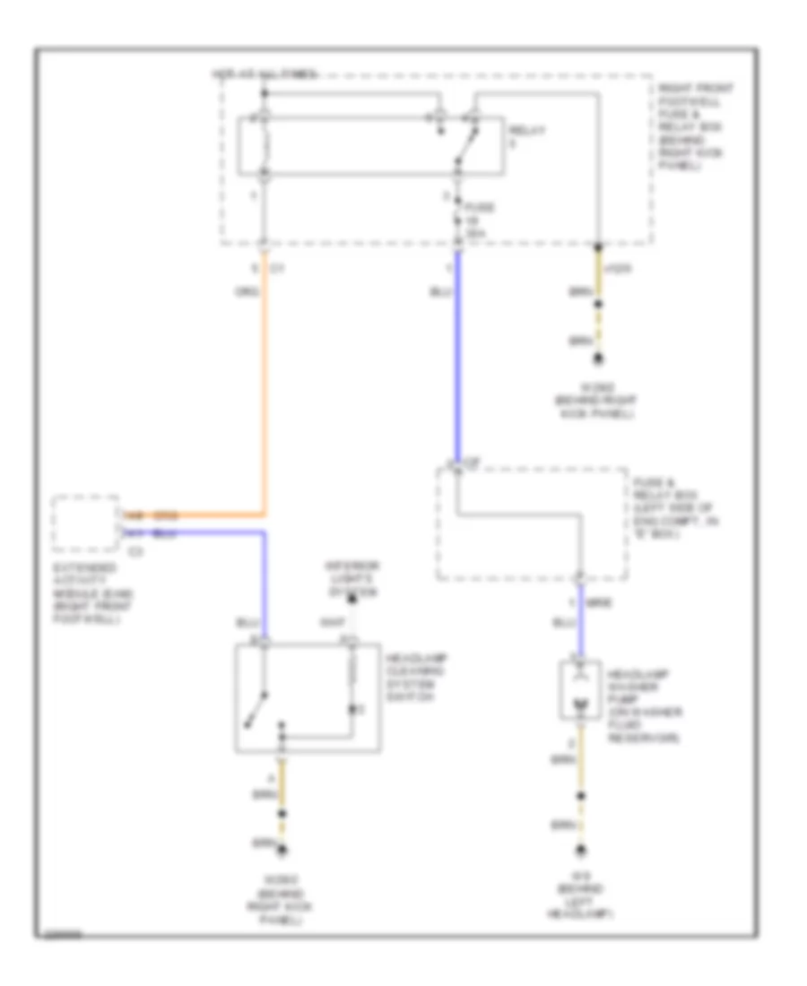
схема шайбы фары для Mercedes-Benz ML500 2004
схема шайбы фары для Mercedes-Benz ML500 2004 - Список элементов:
- (behind right kick panel)
- C/f
- Extended activity module (eam) (right front footwell)
- Fuse & relay box (left side of eng compt, in "e" box)
- Fuse 30a
- Headlamp cleaning system switch
- Headlamp washer pump (on washer fluid reservoir)
- Hot at all times
- Interior lights system
- Mr/e
- Relay
- Right front footwell fuse & relay box (behind right kick panel)
- W29/2
- W29/2 (behind right kick panel)
- W9 (behind left headlamp)
- X12/6
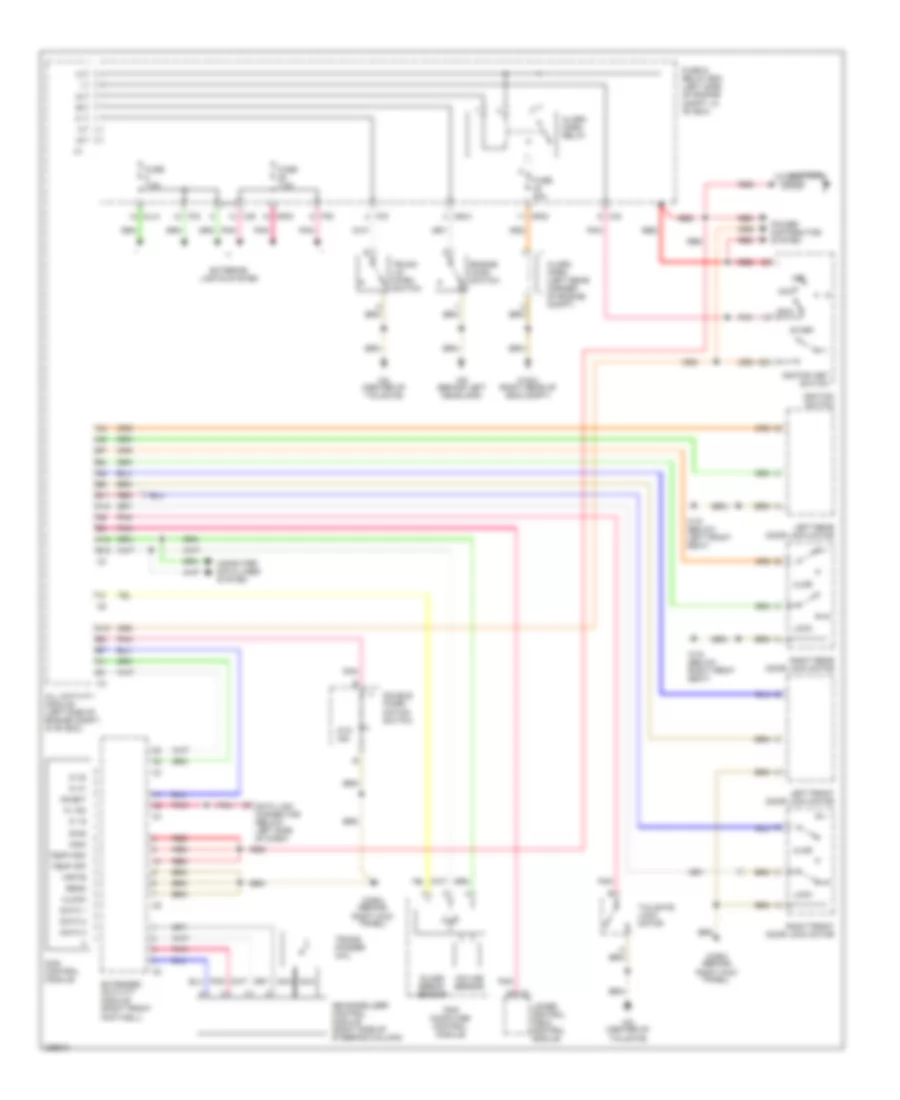
Электросхема заднего стеклоочистителя дворника и омывателя для Mercedes-Benz ML500 2004
Электросхема заднего стеклоочистителя дворника и омывателя для Mercedes-Benz ML500 2004 - Список элементов:
- (ml500) (ml320, ml350)
- Acc
- All activity module (left side of engine compt)
- Battery
- C/c
- C/d
- Fuse & relay box (left side of engine compt, in "e" box)
- Fuse 15a
- Fuse 15a 40a
- Hot in run or start
- Ignition switch
- Illum
- Interior lights system
- Ml/b
- Mr/d
- Off
- Pnk
- Power distribution system
- Rear window washer pump (on washer fluid reservoir)
- Rear window washer pump relay
- Rear window wiper/ washer switch
- Red
- Right front footwell fuse & relay module (behind right kick panel)
- Run
- Start
- Tailgate window wiper motor
- W16/4 (right rear of eng compt)
- W16/5 (left rear of engine compt)
- W29/2 (behind rick kick panel)
- W8 (center of tailgate)
- W9 (behind left headlamp)
- Wash
ЦЕНТРАЛЬНЫЙ ЗАМОК
Электросхема центрального замка для Mercedes-Benz ML500 2004
Электросхема центрального замка для Mercedes-Benz ML500 2004 - Список элементов:
- A10
- Acc
- All activity module (left side of engine compt, in "e" box)
- All doors lock relay
- B10
- B11
- Battery
- C/e
- C/f
- Door ajar
- Door lock
- Filler flap cl actuating motor (left rear cargo area)
- Fuse & relay box (left side of engine compt, in "e" box)
- Fuse 20a
- Ignition switch
- Left front door & fuel filler flap unlock relay
- Left front door lock motor
- Left rear door lock motor
- Lock motor
- Lower control field control module (under center console)
- Off
- P/d
- P/e
- Pnk
- Pnk c/d
- Power distribution
- Red
- Right front door & rear doors unlock relay
- Right front door lock motor
- Right rear door lock motor
- Rotary tumbler trunk lid micro- switch
- Run
- Start
- Tailgate lock motor
- Tailgate unlock relay
- W18 (below left front seat)
- W19 (below right front seat)
- W29/2 (behind right kick panel)
- W8 (center of hatch door)

 Čeština
 Dansk
Dansk Deutsch
 Ελληνικά
 English
 English
 Español
 Suomi
Suomi Français
 Français
 עברית
עברית Hrvatski
 Italiano
 日本語
日本語 한국어
한국어 Nederlands
 Polski
 Português
 Português
 Română
 Русский
 Slovenčina
 Slovenščina
 Svenska
 Türkçe
 中文 (中国)