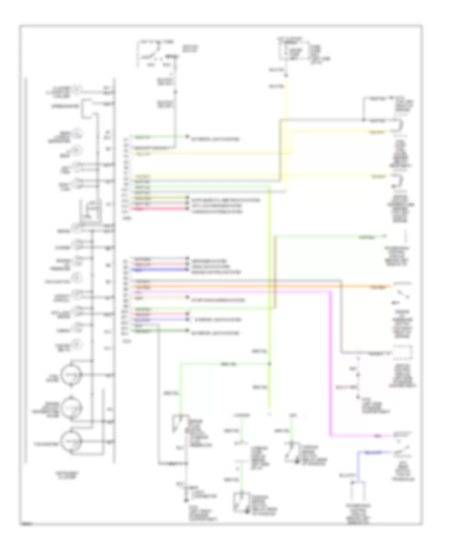
INSTRUMENT CLUSTER
Instrument Cluster Wiring Diagram for Ford Aspire SE 1994
List of elements for Instrument Cluster Wiring Diagram for Ford Aspire SE 1994:
- 5th gear switch (top of transaxle)
- A10
- A11
- A12
- A13
- A14
- Acc
- Airbag
- Anti-lock brake
- Anti-lock brakes system
- B10
- B11
- B12
- B13
- B14
- Brake
- Brake fluid level switch (in brake fluid reservoir)
- C109
- C209
- C210
- Canada
- Charge
- Cluster illumination (4 bulbs)
- Dash fuse box (left side of i/p)
- Defogger system
- Engine controls system
- Engine coolant temperature gauge
- Engine coolant temperature sender (top left side of engine)
- Engine oil pressure
- Engine oil pressure switch (top right front of engine)
- Exterior lights system
- Fasten belts
- Fuel gauge
- Fuel pump/ fuel gauge sender (below rear seat)
- G100 (left front of engine compartment)
- G102 (left side of engine compartment)
- G110 (top left front of engine)
- Headlights system
- Hi beam
- Hot at all times
- Hot in start or run
- Ignition control module (left side of engine compartment)
- Ignition switch
- Instrument cluster
- Interior lights system
- Joint connector
- Left turn
- Lock
- Malfunction
- Meter fuse 15a
- Parking brake switch (below rear of console)
- Pnk
- Powertrain control module (behind left side of i/p)
- Rear window defroster
- Right turn
- Run
- Speedometer
- Start
- Starting/charging system
- Tachometer
- Upshift (manual)
- Usa
- Warning chime module (behind left side of i/p)
- Warning systems system
 English