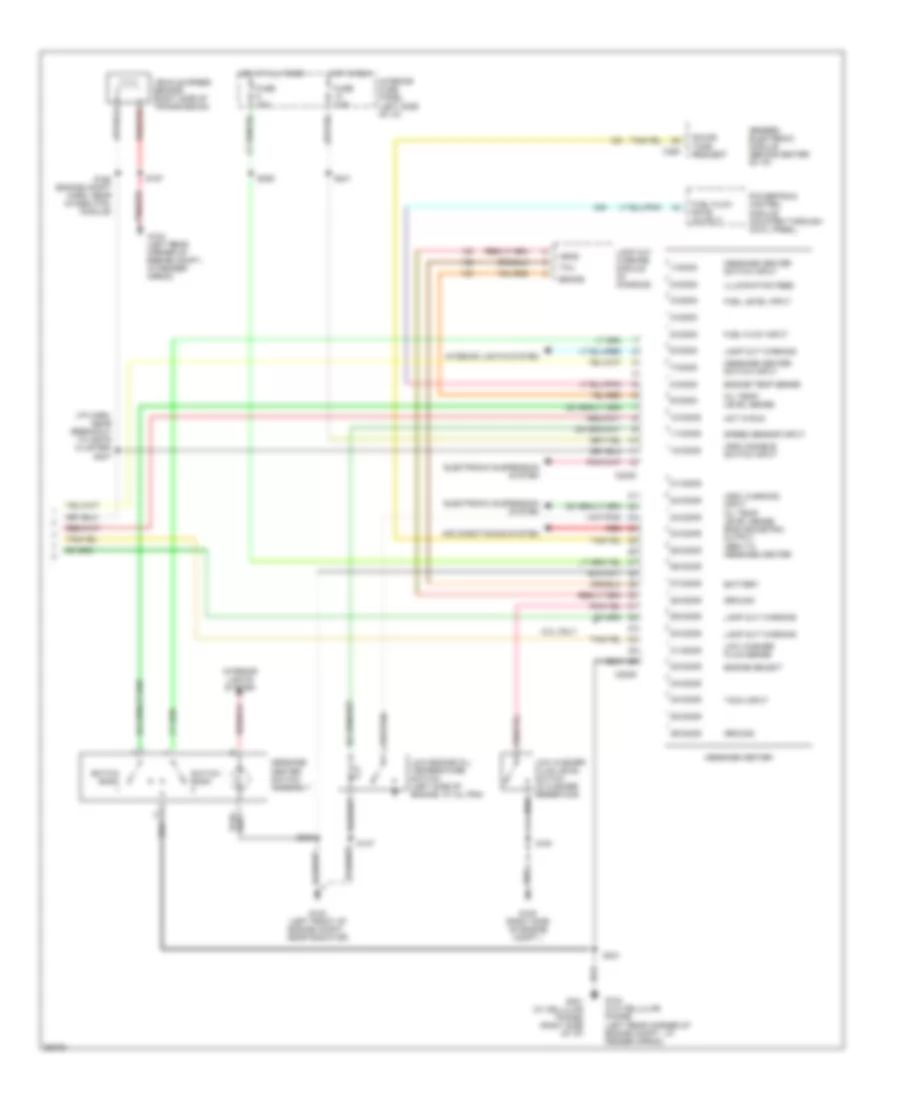
INSTRUMENT CLUSTER
Instrument Cluster Wiring Diagram (1 of 2) for Ford Explorer 1997

List of elements for Instrument Cluster Wiring Diagram (1 of 2) for Ford Explorer 1997:
- "anti-theft" indicator
- "brake" indicator
- "door ajar" indicator
- "fasten seatbelt" indicator
- (4.ol)
- (5.0l)
- (center of i/p) s274
- (early prod)
- (eng compt harn, near a/c relay)
- (eng compt harn, near gem) s275
- (i/p harn, near breakout to inst cluster)
- (late prod)
- 4.0l
- 4.32k
- 4wd indicator (hi-range)
- 4wd indicator (lo-range)
- 5.0l
- Acc
- Air bag indicator
- Anti-lock brakes system
- Anti-lock indicator
- Anti-theft system
- Brake fluid level warning switch (brake fluid reservoir) low
- C286
- C287
- C288
- Charge indicator
- Check gauge
- Cruise control system
- Daytime running lamps (drl) module (left front corner of eng. compt.)
- Dc out
- Dimmer module (left side of steering column)
- Dimmer relay (in relay module, behind center of i/p)
- Engine controls system
- Engine controls system (late prod only)
- Engine coolant temperature gauge
- Engine coolant temperature sender (left front of engine)
- Engine oil pressure gauge
- Engine oil pressure switch (next to power steering pump)
- Exterior lights system
- Fuel guage
- Fuel reset switch indicator
- Fuel tank assembly
- Fuse 15a
- Fuse 7.5a
- G100 (left front of engine compt., near radiator)
- G104 (left rear corner of engine compt., at fender apron)
- G104 (w/o cellular phone) (left rear corner of engine compt., at fender apron)
- G201 (w/ cellular phone) (right side of i/p)
- Head
- Headlamp switch
- Headlights system
- Hi beam
- Hot at all times
- Hot in run or start
- Ignition switch
- Illumination lamps
- Instrument cluster
- Interior fuse panel (left side of i/p)
- Interior lights system
- Left turn
- Lock
- Malfunction indicator lamp
- Off
- Park
- Parking brake switch (on parking brake lever)
- Right turn
- Run
- S128
- S153
- S176 (eng compt harn, near breakout to brk press switch)
- S213
- S214
- S228
- S229
- S232
- S234
- S242
- S264
- S276
- Slosh module
- Speed control indicator
- Speedometer/ odometer
- Start
- Starting/charging system
- Tachometer
- Tachometer data link connector (right rear corner of engine compt)
- Transmission control indicator (tcil)
- Voltmeter
- W/ drl
- W/o drl
- Warning system
Instrument Cluster Wiring Diagram (2 of 2) for Ford Explorer 1997
List of elements for Instrument Cluster Wiring Diagram (2 of 2) for Ford Explorer 1997:
-
- (arc) disable switch input
- (arc) warning input oil temp/ level sense english/metric output (gem) to message center
- (i/p harn, near breakout to instr
- 1/c2008
- 10/c2008
- 11/c2008
- 12/c2008
- 2/c2008
- 21/c2009
- 22/c2009
- 23/c2009
- 24/c2009
- 25/c2009
- 26/c2009
- 27/c2009
- 28/c2009
- 29/c2009
- 3/c2008
- 30/c2009
- 31/c2009
- 32/c2009
- 33/c2009
- 34/c2009
- 35/c2009
- 36/c2009
- 4/c2008
- 5.0l only
- 5/c2008
- 6/c2008
- 7/c2008
- 8/c2008
- 9/c2008
- Air conditioning system
- Battery
- Brake
- C2008
- C2009
- C280
- Cluster) s247
- Electronic suspension system
- Engine select
- Engine temp sense
- Fuel flow input
- Fuel flow rate output
- Fuel level input
- Fuse 10a
- Fuse 7.5a
- G100 (left front of engine compt., near radiator)
- G104 (left rear corner of engine compt., at fender apron)
- G104 (w/o cellular phone) (left rear corner of engine compt., at fender apron)
- G105 (right side of engine compt.)
- G201 (w/ cellular phone) (right side of i/p)
- Generic electronic module (behind center of i/p)
- Ground
- Head
- Hot at all times
- Hot in run
- Illumination feed
- Interior fuse panel (left side of i/p)
- Interior lights system
- Lamp out warning
- Lamp out warning module (in console)
- Low engine oil/ temperature switch (left side of engine, at oil pan)
- Low washer fluid level switch (in washer reservoir)
- Low washer fluid sense
- Message center
- Message center switch assembly
- Message center switch input
- Oil temp/ level sense
- Powertrain control module (mounted through cowl panel)
- Red
- S137
- S157
- S161
- S168 (engine compt harn, near 4wabs ctrl module)
- S209
- S231
- S233
- S241
- Sound tone request
- Speed sensor input
- Switch bank
- Switch bank
- Tach input
- Tail
- Vehicle speed sensor (right side of transmission)
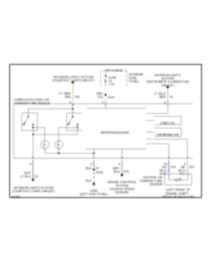
Overhead Console Wiring Diagram for Ford Explorer 1997
List of elements for Overhead Console Wiring Diagram for Ford Explorer 1997:
- (left front of engine compt., front of radiator)
- Compass
- Compass/outside air temperature module
- Engine controls system (vehicle speed sensor)
- Fuse 7.5a
- G200 (left kick panel)
- Hot in run
- Interior fuse panel
- Interior lights system (courtesy lamps circuit)
- Interior lights system (instrument illumination circuit)
- Microprocessor
- Outside air temperature sensor
- S202
- S241
- Thermometer