INSTRUMENT CLUSTER
Analog Cluster Wiring Diagram for Ford Windstar 1995

List of elements for Analog Cluster Wiring Diagram for Ford Windstar 1995:
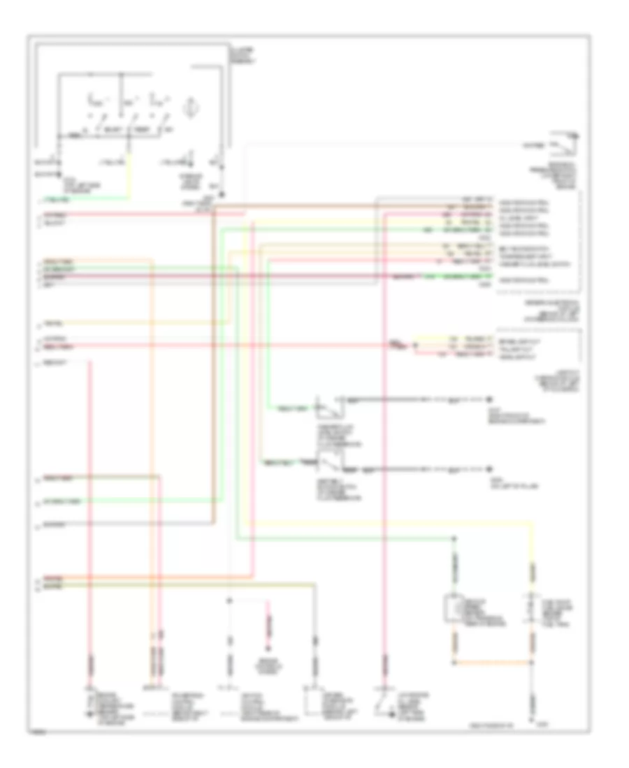
Digital Display Wiring Diagram (1 of 2) for Ford Windstar 1995
List of elements for Digital Display Wiring Diagram (1 of 2) for Ford Windstar 1995:
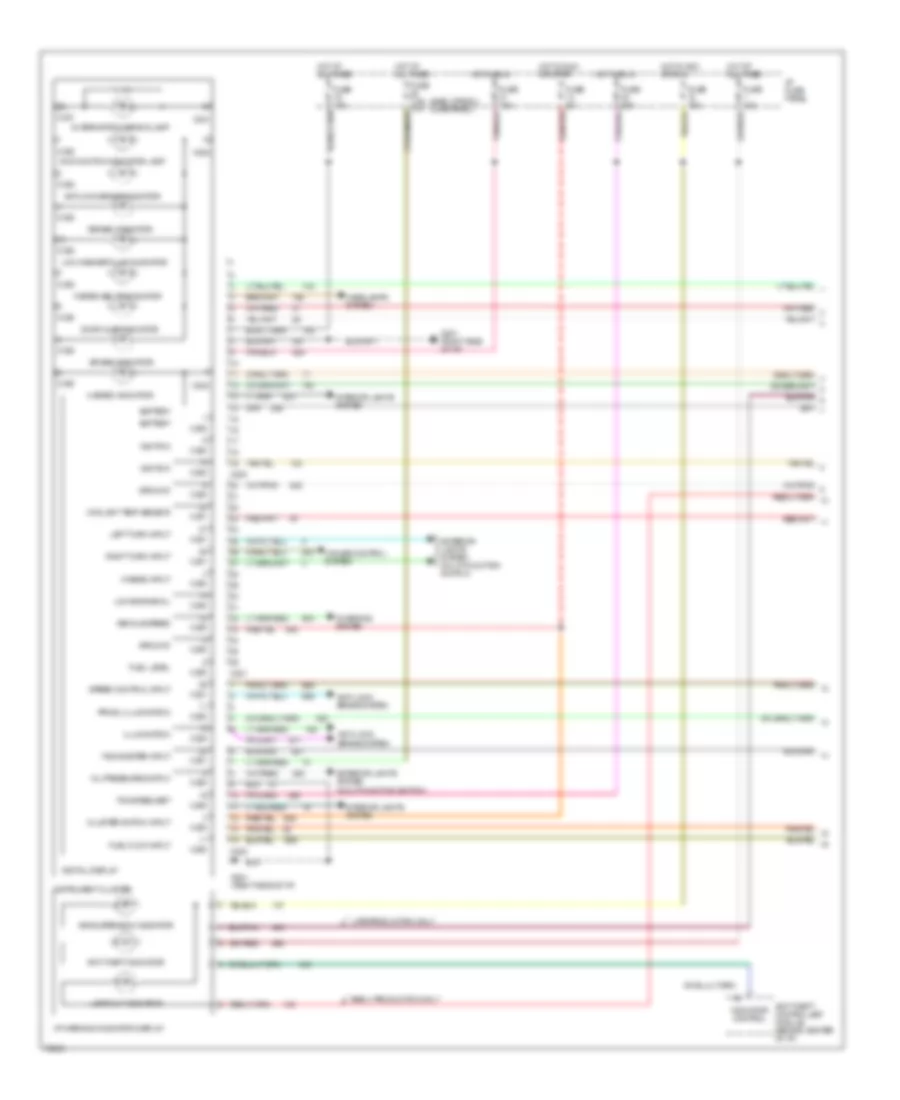
Digital Display Wiring Diagram (2 of 2) for Ford Windstar 1995
List of elements for Digital Display Wiring Diagram (2 of 2) for Ford Windstar 1995: