INSTRUMENT CLUSTER
2.6L
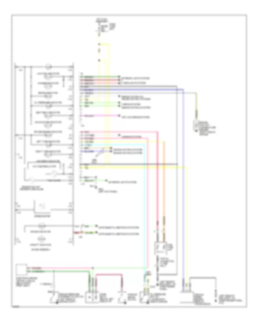
2.6L, Instrument Cluster Wiring Diagram, Early Production for Isuzu Rodeo S 1995

List of elements for 2.6L, Instrument Cluster Wiring Diagram, Early Production for Isuzu Rodeo S 1995:
- A10
- A11
- A12
- B10
- B11
- B12
- Brake warning light
- C211
- C274
- C275
- Charge warning light
- Charging system (generator)
- Check engine malfunction indicator lamp
- Combination valve pressure differential switch (in brake fluid valve)
- Dash fuse box
- Diode box d
- Engine control module (ecm) (left kick panel)
- Engine controls system (diode box a)
- Engine controls system (engine control module ecm)
- Engine coolant temperature (ect) gauge sender (right side of engine below intake manifold)
- Engine coolant temperature gauge
- Exterior lights system (combination switch)
- Fuel gauge
- Fuel tank unit (right front of fuel tank)
- Fuse 10a
- G200 (left side kick panel)
- G415 (under body, ahead of rear bumper)
- Headlights system
- Hi beam indicator light
- Hot in on or start
- Illumination (2 bulbs w/ tachometer) (9 bulbs w/o tachometer)
- Indicator cancel switch
- Instrument cluster
- Interior lights system
- Internal voltage regulator
- Left turn indicator light
- Low fuel warning light
- O2 sensor indicator light
- Oil pressure switch (lower front of engine)
- Oil pressure warning light
- Parking brake switch (on parking brake lever)
- Pnk
- Rear wheel anti-lock brake controller (below right front seat)
- Red
- Right turn indicator light
- Rr antilock brake warning light
- Seatbelt warning light
- Vehicle speed sensor
- Warning system (warning buzzer control unit)
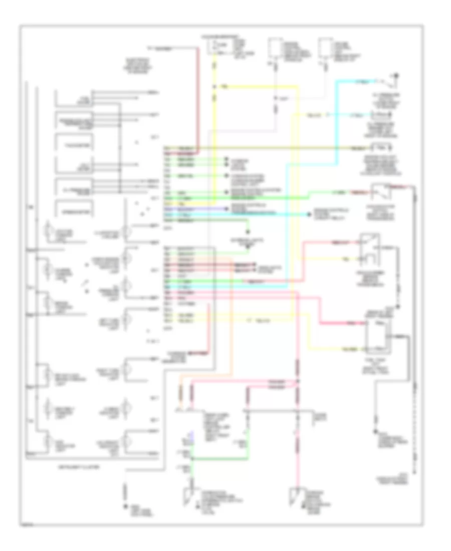
2.6L, Instrument Cluster Wiring Diagram, Late Production for Isuzu Rodeo S 1995
List of elements for 2.6L, Instrument Cluster Wiring Diagram, Late Production for Isuzu Rodeo S 1995:
- (left rear of eng compt, 0n inner fender panel) g104
- (left rear of eng compt, on inner fender panel)
- (not used)
- (pigtail connection in 1995 only)
- 1-15
- Air bag indicator
- Anti-lock brake system
- Brake indicator
- Brake pressure differential switch (left rear of engine compt)
- Charge indicator
- Charging system
- Dash fuse box
- Diode box d (below left side of i/p)
- Electronic brake control module (below right front seat)
- Engine controls & cruise control systems
- Engine controls system
- Engine coolant temperature gauge
- Engine coolant temperature sender (right side of engine)
- Exterior lights system
- Fuel gauge
- Fuel tank unit
- G104
- G200 (left kick panel)
- Gauge assembly
- Headlights system
- High beam indicator
- Hot in on or start
- I-16
- I-28
- Left turn indicator
- Low fuel indicator
- Malfunction indicator
- Meter cb-7 15a
- Oil pressure indicator
- Oil pressure switch (lower right side of engine)
- Only
- Parking brake switch
- Pnk
- Red
- Right turn indicator
- Rr abs brake indicator
- Seat belt indicator
- Speedometer
- Upshift indicator
- Vehicle speed sensor (rear of transmission)
- Voltage regulator
- Warning system
3.2L
3.2L, Instrument Cluster Wiring Diagram, Early Production for Isuzu Rodeo S 1995
List of elements for 3.2L, Instrument Cluster Wiring Diagram, Early Production for Isuzu Rodeo S 1995:
- 4wd indicator light
- 4wd indicator switch (right side of transmission)
- A10
- A11
- A12
- A13
- A14
- B10
- B11
- B12
- B13
- B14
- Brake warning light
- C274
- C275
- Charge warning light
- Charging system (generator)
- Check engine malfunction indicator lamp
- Combination valve pressure differential switch (in brake fluid valve)
- Cruise control unit (behind right side of i/p)
- Dash fuse box (left side of i/p)
- Diode box d
- Electronic ignition (ei) (center front of engine)
- Engine control module (ecm) (behind front console)
- Engine controls system (engine control module ecm)
- Engine controls system (transmission switch)
- Engine controls system (upshift relay)
- Engine coolant temperature gauge
- Engine coolant temperaure (ect) gauge sender (rear of engine in coolant manifold)
- Exterior lights system
- Fuel gauge
- Fuel tank unit (right front of fuel tank)
- Fuse 10a
- G101 (middle of right front fender)
- G104 (rear of left front fender)
- G200 (left side kick panel)
- G415 (under body, ahead of rear bumper)
- Headlights system
- Hi beam indicator light
- Hot in on or start
- Illumination (4 bulbs)
- Instrument cluster
- Interior lights system
- Left turn indicator light
- Low fuel warning light
- Oil pressure gauge
- Oil pressure sender unit (lower left front of engine)
- Oil pressure switch (lower front of engine)
- Oil pressure warning light
- Parking brake switch (on parking brake lever)
- Pnk
- Rear wheel anti-lock brake controller (below right front seat)
- Right turn indicator light
- Rr antilock brake warning light
- Seatbelt warning light
- Speedometer
- Tachometer
- U/s upshift indicator light (m/t)
- Vehicle speed sensor (rear of transmission)
- Volt meter
- Warning system (warning buzzer control unit)
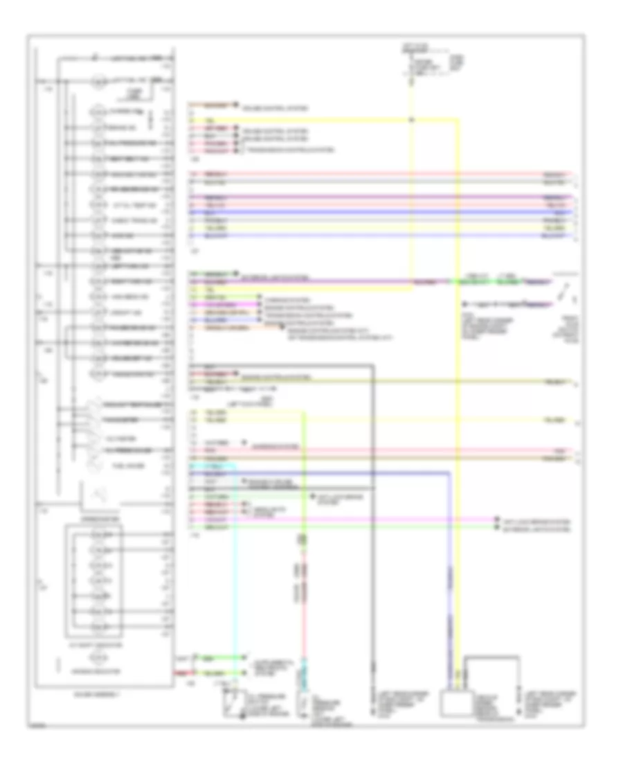
3.2L, Instrument Cluster Wiring Diagram, Late Production (1 of 2) for Isuzu Rodeo S 1995
List of elements for 3.2L, Instrument Cluster Wiring Diagram, Late Production (1 of 2) for Isuzu Rodeo S 1995:
- (1995 a/t)
- (1995)
- (1996)
- (exc 95 a/t)
- (left rear corner of eng compt, on inner fender panel) g104
- 4wd ind
- A/t oil temp ind
- A/t shift indicator
- Abs active ind
- Air bag indicator
- Anti-lock brake system
- Brake ind
- Charge ind
- Charging system
- Check trans ind
- Coolant temp gauge
- Cruise control system
- Cruise main ind
- Cruise set ind
- Dash fuse box
- Engine & cruise control systems
- Engine controls system
- Engine controls system (m/t)
- Exterior lights system
- Front axle switch (on front axle)
- Fuel gauge
- G104 (left rear corner of engine compt, on inner fender panel)
- G200 (left kick panel)
- Gauge assembly
- Headlights system
- High beam ind
- Hot in on or start
- I-15
- I-16
- I-26
- I-27
- I-28
- Left turn ind
- Low fuel ind
- Malfunction ind
- Meter fuse cb-7 15a
- Oil press gauge
- Oil pressure ind
- Oil pressure sending unit (lower left side of engine)
- Oil pressure switch (lower left side of engine)
- Or transmission control system (a/t)
- Pnk
- Power drive ind
- Red
- Right turn ind
- Rr abs brake ind
- Seat belt ind
- Speedometer
- Tachometer
- Timer (1995)
- Transmission controls system
- Upshift ind
- Vehicle speed sensor (rear of transmission)
- Voltmeter
- Warning system
- Winter drive ind
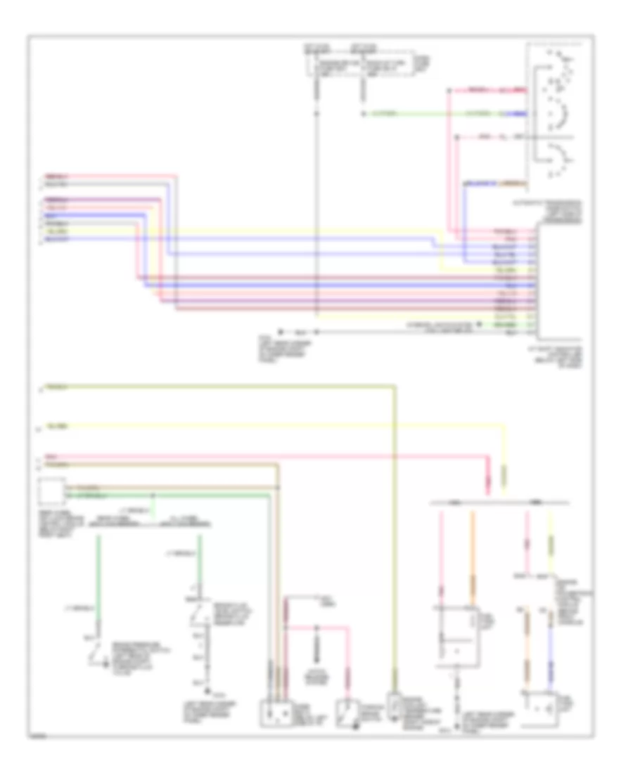
3.2L, Instrument Cluster Wiring Diagram, Late Production (2 of 2) for Isuzu Rodeo S 1995
List of elements for 3.2L, Instrument Cluster Wiring Diagram, Late Production (2 of 2) for Isuzu Rodeo S 1995:
- (left rear corner of engine compt, on inner fender panel)
- (not used)
- A/t shift indicator controller (below left side of dash)
- All wheel anti-lock brakes
- Automatic transmission mode switch (left side of transmission)
- B15
- Back-up turn fuse cb-15 15a
- Brake fluid level switch (brake fluid reservoir)
- Brake pressure differential switch (left rear of engine compt, in brake fluid valve)
- C13
- Dash fuse box
- Diode box d (below left side of i/p)
- Engine coolant temperature sender (right side of engine)
- Engine device fuse cb-3 15a
- Engine or powertrain control module (behind front console)
- Fuel tank unit
- G104
- G104 (left rear corner of engine compt, on inner fender panel)
- Hatch release system
- Hot in on or start
- Interior lights system (taillight relay)
- Parking brake switch
- Pnk
- Rear wheel anti-lock brake control module (below right front seat)
- Rear wheel anti-lock brakes