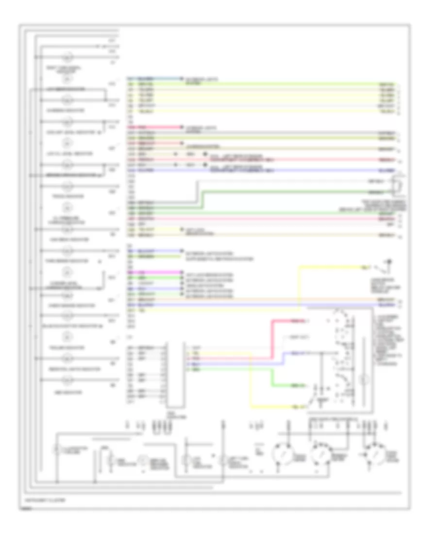
INSTRUMENT CLUSTER
Instrument Cluster Wiring Diagram, VDO (1 of 2) for Volvo 850 Turbo 1994

List of elements for Instrument Cluster Wiring Diagram, VDO (1 of 2) for Volvo 850 Turbo 1994:
- (left rear of engine
- 1. avg speed 2. instant fuel consumption 3. avg fuel consumption 4. outside temp 5. distance since last reset 6. distance to empty 7. diagnosis
- 5v reg
- 8v reg
- A10
- A11
- A12
- A13
- A14
- A15
- A16
- A17
- A18
- A19
- A20
- A21
- A22
- A23
- A24
- A25
- A26
- A27
- A28
- A29
- A30
- Abs indicator
- Anti-lock brake system
- B10
- B11
- B12
- B13
- B14
- B15
- B16
- Brake warning indicator
- Bulb malfunction indicator
- Charging indicator
- Charging system
- Check engine indicator
- Coolant level indicator
- D10
- D11
- Exterior lights system
- Fuel gauge
- Fuel indicator
- G104 compartment, in fuse/relay box)
- Hand brake switch (below center console)
- Headlights system
- High beam indicator
- Illumination (4 bulbs)
- Indicator
- Instrument cluster
- Interior lights system
- Kedt
- Kefa
- Left turn
- Low
- Low gear indicator
- Low oil level indicator
- Microprocessor
- Obd socket a (right front of engine compartment)
- Oil pressure
- Park brake indicator
- Pnk
- Rear fog lights indicator
- Reset
- Right turn signal
- Service reminder indicator
- Signal indicator
- Speedo- meter
- Srs
- Srs indicator
- Tacho- meter
- Temperature gauge
- Tracs indicator
- Trailer indicator
- Trip computer
- Trip computer ambient temperature sensor (behind left side of front bumper)
- Trip computer controls
- Warning indicator
- Washer level
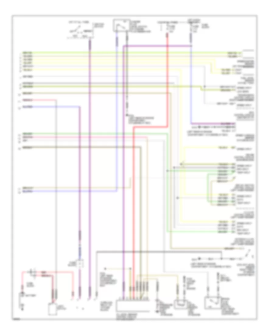
Instrument Cluster Wiring Diagram, VDO (2 of 2) for Volvo 850 Turbo 1994
List of elements for Instrument Cluster Wiring Diagram, VDO (2 of 2) for Volvo 850 Turbo 1994:
- (left rear of engine
- (left rear of engine compartment, in fuse/relay box)
- A24
- Acc
- Battery
- Brake fluid level switch (left rear of engine compartment)
- Compartment, in fuse/relay box)
- Coolant level sensor (right front of engine compartment)
- Cruise control module (in fuse block)
- Data
- Ecc control module (center of i/p)
- Ezk (di) ignition control module (left inner fender)
- Fuel level sensor (in fuel tank)
- Fuse 11-15 10a
- Fuse 11-3 10a
- Fuse block
- G104
- G104 (left rear of engine compartment, in fuse/relay box)
- G111 (below battery)
- G125 (lower front of engine)
- Hot at all times
- Hot in run or start
- Ignition switch
- Lh 3.2 mfi control module (left inner fender)
- Light switch
- Low gear
- Motronic 4.3 mfi control module (left inner fender)
- Off
- Oil level sensor (left side of engine)
- Oil level sensor control module (in fuse block)
- Oil pressure sensor (left side of engine)
- Overload relay 15+ (in fuse block)
- Red
- Rpm input
- Run
- Speed input
- Speed warning beeper (in fuse block)
- Speedometer sensor (on transmission)
- Start
- Temp input
- Transmission control module (right inner fender)
- Washer fluid level switch (in washer fluid reservoir)
Instrument Cluster Wiring Diagram, Yasaki (1 of 2) for Volvo 850 Turbo 1994
List of elements for Instrument Cluster Wiring Diagram, Yasaki (1 of 2) for Volvo 850 Turbo 1994:
- (left rear of engine
- 1. avg speed 2. instant fuel consumption 3. avg fuel consumption 4. outside temp 5. distance since last reset 6. distance to empty 7. diagnosis
- 5v reg
- A10
- A11
- A12
- A13
- A14
- A15
- A16
- A17
- A18
- A19
- A20
- A21
- A22
- A23
- A24
- A25
- A26
- A27
- A28
- A29
- A30
- Abs indicator
- Anti-lock brake system
- B10
- B11
- B12
- B13
- B14
- B15
- B16
- Brake warning indicator
- Bulb malfunction indicator
- Charging indicator
- Charging system
- Check engine indicator
- Coolant level indicator
- D10
- D11
- Exterior lights system
- Fuel indicator
- G104 compartment, in fuse/relay box)
- Hand brake switch (below center console)
- Headlights system
- High beam indicator
- Illumination (4 bulbs)
- Indicator
- Instrument cluster
- Interior lights system
- Left turn
- Low
- Low gear indicator
- Low oil level indicator
- Oil pressure
- Park brake indicator
- Pnk
- Rear fog lights indicator
- Reset
- Right turn signal
- Service reminder indicator
- Signal indicator
- Speedo- meter
- Srs
- Srs indicator
- Tacho- meter
- Tank/ temp gauge
- Tracs indicator
- Trailer indicator
- Trip computer
- Trip computer ambient temperature sensor (behind left side of front bumper)
- Trip computer controls
- Warning indicator
- Washer level
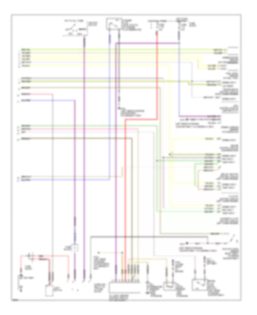
Instrument Cluster Wiring Diagram, Yasaki (2 of 2) for Volvo 850 Turbo 1994
List of elements for Instrument Cluster Wiring Diagram, Yasaki (2 of 2) for Volvo 850 Turbo 1994:
- (left rear of engine
- (left rear of engine compartment, in fuse/relay box)
- A24
- Acc
- Battery
- Brake fluid level switch (left rear of engine compartment)
- Compartment, in fuse/relay box)
- Coolant level sensor (right front of engine compartment)
- Cruise control module (in fuse block)
- Ecc control module (center of i/p)
- Ezk (di) ignition control module (left inner fender)
- Fuel level sensor (in fuel tank)
- Fuse 11-15 10a
- Fuse 11-3 10a
- Fuse block
- G104
- G104 (left rear of engine compartment, in fuse/relay box)
- G111 (below battery)
- G125 (lower front of engine)
- Hot at all times
- Hot in run or start
- Ignition switch
- Lh 3.2 mfi control module (left inner fender)
- Light switch
- Low gear
- Motronic 4.3 mfi control module (left inner fender)
- Off
- Oil level sensor (left side of engine)
- Oil level sensor control module (in fuse block)
- Oil pressure sensor (left side of engine)
- Overload relay 15+ (in fuse block)
- Red
- Rpm input
- Run
- Speed input
- Speed warning beeper (in fuse block)
- Speedometer sensor (on transmission)
- Start
- Temp input
- Transmission control module (right inner fender)
- Washer fluid level switch (in washer fluid reservoir)