INSTRUMENT CLUSTER
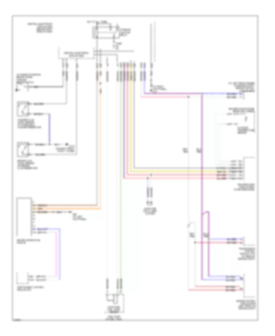
Instrument Cluster Wiring Diagram for Volvo S40 2005
List of elements for Instrument Cluster Wiring Diagram for Volvo S40 2005:
- (at base of parking brake lever) parking brake switch
- (at left rear corner of engine compt) brake control module (bcm)
- (at right kick panel) g10
- A10
- A12
- A17
- A28
- A38
- B14
- Brake fluid level sensor (on brake fluid reservoir)
- Central electronic module (cem)
- Central electronic module (cem) (behind right side of dash)
- Computer data lines system
- Driver information module
- Driver's door module (ddm) (in driver's door)
- Driver's door power rear-view mirror
- Engine control module (ecm) (left front of engine compt)
- F15
- F25
- F28
- F30
- F31
- Fuel pump (in fuel tank)
- Fuse 5a
- G110 (on right front strut tower)
- G14
- G15
- G27
- G28
- G83 (at left kick panel)
- Hot at all times
- Infotainment control module (icm)
- Interior lighting relay
- Outdoor temperature sensor
- Pump side fuel level sensor
- Transmission control module (tcm) (at rear of engine compt)
- Washer fluid level sensor (in windshield washer reservoir)
 English