INSTRUMENT CLUSTER
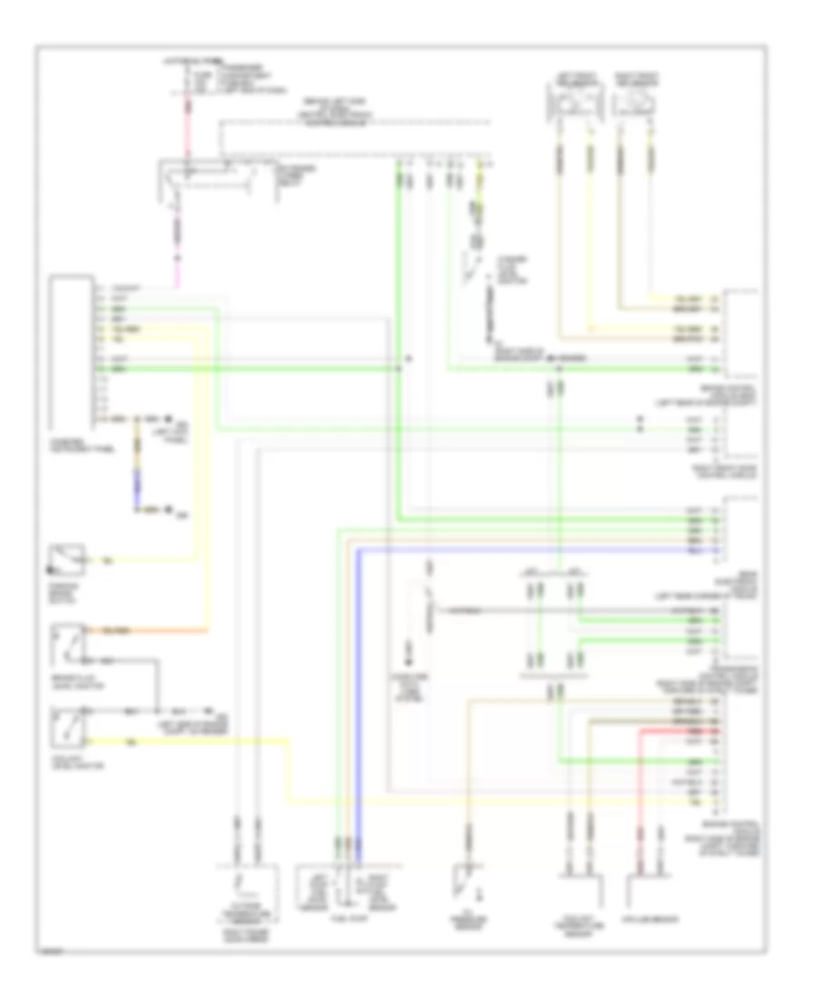
Instrument Cluster Wiring Diagram for Volvo S80 2004
List of elements for Instrument Cluster Wiring Diagram for Volvo S80 2004:
- (behind left side of dash) central electronic control module
- A/t
- Brake control module (bcm) (left rear of engine compt)
- Brake fluid level monitor
- Combined instrument panel
- Computer data lines system
- Coolant level monitor
- Coolant temperature sensor
- Engine control module (right side of engine compt, forward of strut tower)
- Extended x-feed relay
- Fuel pump
- Fuse c24 10a
- G1 (right side of engine compt, on fender)
- G83 (left kick panel)
- G93 (left side of engine compt, on fender)
- G98
- Hot at all times
- Impulse sensor
- Left front abs sensor
- Left pump fuel level sensor
- M/t
- Oil pressure sensor
- Outside temperature sensor
- Parking brake switch
- Passenger compartment fuse box (left end of dash)
- Rear electronic module (left rear corner of trunk)
- Red
- Right front abs sensor
- Right front door control module
- Right power door mirror
- Right pump fuel level sensor
- Transmission control module (right side of engine compt, forward of strut tower)
- Washer fluid level monitor
 English