POWER DISTRIBUTION
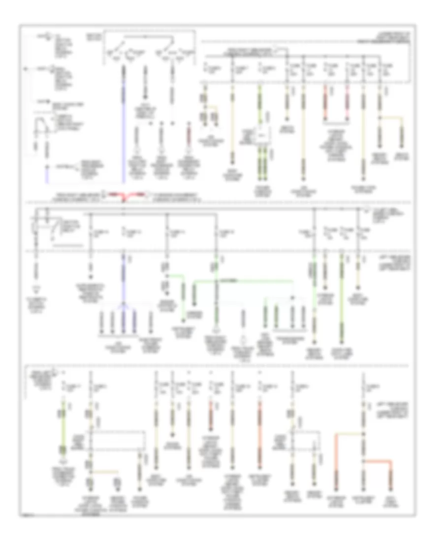
Power Distribution Wiring Diagram (1 of 4) for Jaguar XJR 2003
 https://portal-diagnostov.com/license.html
Automotive Electricians Portal FZCO
Automotive Electricians Portal FZCO
https://portal-diagnostov.com/license.html
https://portal-diagnostov.com/license.html
Automotive Electricians Portal FZCO
Automotive Electricians Portal FZCO
List of elements for Power Distribution Wiring Diagram (1 of 4) for Jaguar XJR 2003:
- (diagram 1 of 4)
- (in trunk, next to battery) high power protection module
- (not used)
- (right rear wheelwell) bt65
- (right side of trans tunnel) ca47
- (right side of trunk) trunk fuse box
- Accessory connector relay (relay 6)
- After dealer prep
- Air conditioning system
- Auxiliary positive relay
- Battery
- Before dealer prep
- Body computer system
- Body processor module (behind glove box)
- Bt10
- Bt11
- Bt12
- Bt13
- Bt21 (right rear side of trunk)
- Bt25
- Bt37
- Ca37 (right "a" pillar)
- Ca41
- Ca42
- Ca71
- Ca74
- Ca75
- Ca76
- Computer data lines system
- Defogger system
- Door locks system
- Engine controls system
- Exterior lights system
- Fc15
- From high power protection module c
- From trunk fuse box (diagram 1 of 4)
- From v trunk fuse box (diagram 1 0f 4)
- Front cigar lighter
- Fuel pump relay 1 (relay 4)
- Fuel pump relay 2 (relay 1) (super charged engine only)
- Fuse
- Fuse (not used)
- Fuse 1 20a
- Fuse 10a
- Fuse 15 20a
- Fuse 2 15a
- Fuse 25a
- Fuse 3 15a
- Fuse 4 10a
- Fuse 5 25a
- Fuse 5 5a
- Fuse 5a
- Fuse 7 20a
- Heated backlight relay (relay 2)
- Interior lights system
- Interior lights, navigation, cellular telephone systems
- Mirrors system
- Output
- Passenger compartment accessory connector (right kick panel)
- Power fuse 250a
- Power fuse 500a
- Rear cigar lighter
- Red
- Right heelboard fuse box (under front of right rear seat)
- Right heelboard fuse box (under front of right seat)
- Seats system
- Seats, memory systems
- Side marker & number plate relay (relay 3)
- Sound systems, warning systems
- Starting/ charging system
- Stop- lamp relay (relay 5)
- To ignition switch (diagram 2 of 4)
- To left heelboard fuse box (diagram 2 of 4)
- To right heelboard fuse box (diagram 1 of 4)
- To right heelboard fuse box (diagram 2 of 4)
- To trunk accessory connector (diagram 1 of 4)
- To trunk fuse box (diagram 1 of 4)
- To trunk fuse box (diagram 4 of 4)
- Transit isolation device (in trunk, next to battery)
- Trunk accessory connector (adjacent to battery)
- Trunk fuse box (right side of trunk)
- Wake-up grd
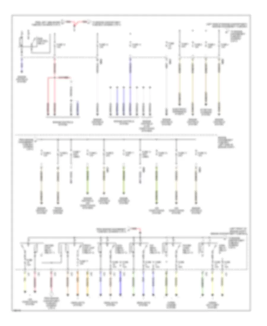
Power Distribution Wiring Diagram (2 of 4) for Jaguar XJR 2003
List of elements for Power Distribution Wiring Diagram (2 of 4) for Jaguar XJR 2003:
- (under front of right rear seat) right heelboard fuse box
- Acc
- Air conditioning system
- Anti- lock brakes, memory, seats systems
- Anti- theft system
- Body computer system
- Ca1
- Ca2
- Ca222
- Ca222 (right heel- board)
- Ca223
- Ca223 (right heel- board)
- Ca224
- Ca224 (left heel- board)
- Ca41
- Ca42
- Computer data lines system
- Electronic power steering system
- Engine controls system
- Exterior lights system
- Fc17 (center of dash, on firewall)
- From accessory connector relay (diagram 1 of 4)
- From auxiliary positive relay (diagram 1 of 4)
- From body processor module (diagram 1 of 4)
- From ignition positive relay (diagram 2 of 4)
- From left n heelboard fuse box (diagram 2 of 4)
- From right heelboard f fuse box (diagram 1 of 4)
- From right heelboard fuse box (diagram 1 of 4)
- From right heelboard h fuse box (diagram 1 of 4)
- From trunk
- From trunk accessory connector (diagram 1 of 4)
- Fuse 1 20a
- Fuse 10 5a
- Fuse 10a
- Fuse 12 10a
- Fuse 14 10a
- Fuse 15 25a
- Fuse 15a
- Fuse 16 10a
- Fuse 17 10a
- Fuse 18 5a
- Fuse 2 5a
- Fuse 20a
- Fuse 25a
- Fuse 5a
- Fuse 6 10a
- Fuse 6 5a
- Fuse 7 20a
- Fuse 8 5a
- Fuse box (diagram 1 of 4)
- Ignition positive relay
- Ignition switch
- Iii
- Inertia switch (behind right kick panel)
- Instrument cluster
- Instrument cluster system
- Interior lights system
- Interior lights, door locks, power windows systems
- Interior lights, memory, door locks, anti-theft, power windows systems
- Interior lights, memory, door locks, anti-theft, power windows, mirrors systems
- Interior lights, memory, door locks, power windows, anti-theft, mirrors systems
- Left heelboard fuse box (under front of left rear seat)
- Memory system
- Memory, power windows systems
- Memory, seats systems
- Mirrors system
- Nca
- Off
- Power tops systems
- Power windows system
- Red
- Run
- Seats system
- Sound systems
- Start
- To engine management fuse box (diagram 3 of 4)
- To ignition positive relay (diagram 4 of 4)
- To inertia switch (diagram 2 of 4)
- To left heel- board fuse box diagram 2 of 4)
- Transmissions system
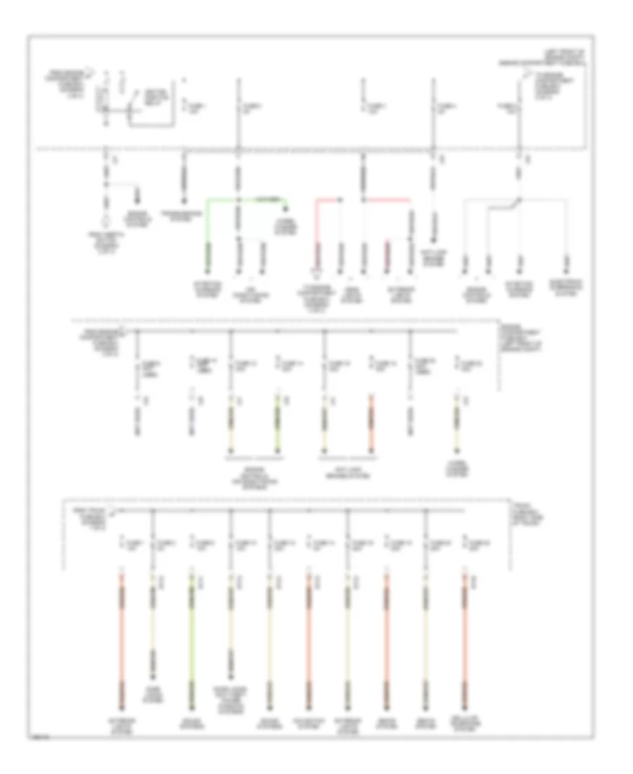
Power Distribution Wiring Diagram (3 of 4) for Jaguar XJR 2003
List of elements for Power Distribution Wiring Diagram (3 of 4) for Jaguar XJR 2003:
- (left front of engine compt) engine compartment fuse box
- (left side of engine compartment) engine management fuse box
- (not used)
- Air conditioning system
- Dip beam relay (relay 5)
- Electronic suspension sysetm
- Em19
- Em20
- Ems control relay
- Engine controls & air conditioning systems
- Engine controls system
- Engine controls, air conditioning systems
- Engine management fuse box (left side of engine compt)
- From engine compartment fuse box (diagram 4 of 4)
- From engine management p fuse box (diagram 3 of 4)
- From engine q management fuse box (diagram 3 of 4)
- From left heelboard j fuse box (diagram 2 of 4)
- Front fog lamp relay (relay 2)
- Fuse 1 20a
- Fuse 10 10a
- Fuse 10a
- Fuse 11 30a
- Fuse 12 10a
- Fuse 13 (not used)
- Fuse 14 10a
- Fuse 15 30a
- Fuse 17 15a
- Fuse 17 30a
- Fuse 18 10a
- Fuse 2 15a
- Fuse 3 25a
- Fuse 30a
- Fuse 4 10a
- Fuse 5 10a
- Fuse 5a
- Fuse 6 5a
- Fuse 7 (not used)
- Fuse 8 10a
- Fuse 9 30a
- Headlights system
- Heater pump relay (relay 1)
- Horn relay (relay 6)
- Horns/ anti-theft system
- Lf5
- Lf6
- Lf7
- Lf8
- Main beam relay (relay 3)
- Power- wash relay (relay 4)
- Red
- Starting/ charging system
- To engine compartment fuse box (diagram 3 of 4)
- To engine compartment fuse box (diagram 4 of 4)
- To engine management fuse box (diagram 3 of 4)
- Trans- missions system
- Wiper/ washer system
Power Distribution Wiring Diagram (4 of 4) for Jaguar XJR 2003
List of elements for Power Distribution Wiring Diagram (4 of 4) for Jaguar XJR 2003:
- (left front of engine compt) engine compartment fuse box
- (not used)
- Air conditioning system
- Anti-lock brakes system
- Bt10
- Bt11
- Bt12
- Bt13
- Cellular telephone system
- Door locks system
- Door locks, anit-theft, power windows systems
- Electronic suspension system
- Engine compartment fuse box (left front of engine compt)
- Engine controls system
- Engine controls, air conditioning systems
- Exterior lights system
- From engine r compartment fuse box (diagram 3 of 4)
- From engine t compartment fuse box (diagram 4 of 4)
- From inertia switch (diagram 2 of 4)
- From trunk w fuse box (diagram 1 of 4)
- Fuse 1 10a
- Fuse 10 (not used)
- Fuse 10 10a
- Fuse 12 30a
- Fuse 14 30a
- Fuse 14 5a
- Fuse 16 20a
- Fuse 16 30a
- Fuse 18 20a
- Fuse 18 30a
- Fuse 2 5a
- Fuse 20 (not used)
- Fuse 20 20a
- Fuse 22 20a
- Fuse 22 30a
- Fuse 3 10a
- Fuse 4 5a
- Fuse 5 10a
- Fuse 9 (not used)
- Fuse 9 10a
- Head lights system
- Ignition positive relay
- Lf5
- Lf6
- Lf7
- Lf8
- Navigation system
- Seats system
- Sound systems
- Starting/ charging system
- To engine compartment fuse box (diagram 3 of 4)
- To engine compartment fuse box (diagram 4 of 4)
- Transmissions system
- Trunk fuse box (right side of trunk)
- Wiper/ washer system

 Čeština
 Dansk
Dansk Deutsch
 Ελληνικά
 English
 English
 Español
 Suomi
Suomi Français
 Français
 עברית
עברית Hrvatski
 Magyar
 日本語
日本語 한국어
한국어 Nederlands
 Polski
 Português
 Português
 Română
 Русский
 Slovenčina
 Slovenščina
 Svenska
 Türkçe
 中文 (中国)