SUPPLEMENTAL RESTRAINTS
Supplemental Restraints Wiring Diagram for Hyundai Santa Fe 2004
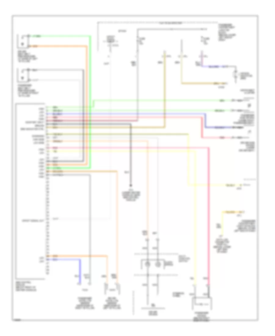
List of elements for Supplemental Restraints Wiring Diagram for Hyundai Santa Fe 2004:
- Air bag indicator (srs)
- Clock- spring
- Data link connector (partial) (behind lower left end of dash)
- Diagnosis
- Driver air bag
- Driver satellite sensor (near base of left "b" pillar)
- Driver seat belt pretensioner (at base of left ``b" pillar)
- Driver side air bag (under driver seat)
- Etacm
- Fuse 10a
- Fuse 15a
- G14 (under center console, near srs control module)
- Ground
- High
- High side
- Hot in on or start
- I/p-j
- I/p-k
- I/p-l
- Impact signal input
- Impact signal out
- Instrument cluster
- Low
- Low side
- M13-3
- M15-5
- Multi- function switch
- Nca
- On/start input
- Passenger air bag (behind right side of dash)
- Passenger compartment junction block (behind lower left end of dash)
- Passenger satellite sensor (near base of right "b" pillar)
- Passenger seat belt pretensioner (at base of right ``b" pillar)
- Passenger side air bag (under front passenger seat)
- Pnk
- Red
- Srs control module (below front of center console)
- Srs indicator ctrl
- Steering wheel
 Čeština
 Dansk
Dansk Deutsch
 Ελληνικά
 English
 English
 Español
 Suomi
Suomi Français
 Français
 עברית
עברית Hrvatski
 Magyar
 日本語
日本語 한국어
한국어 Nederlands
 Polski
 Português
 Português
 Română
 Русский
 Slovenčina
 Slovenščina
 Svenska
 Türkçe
 中文 (中国)
 Italiano