ENGINE PERFORMANCE
2.5L
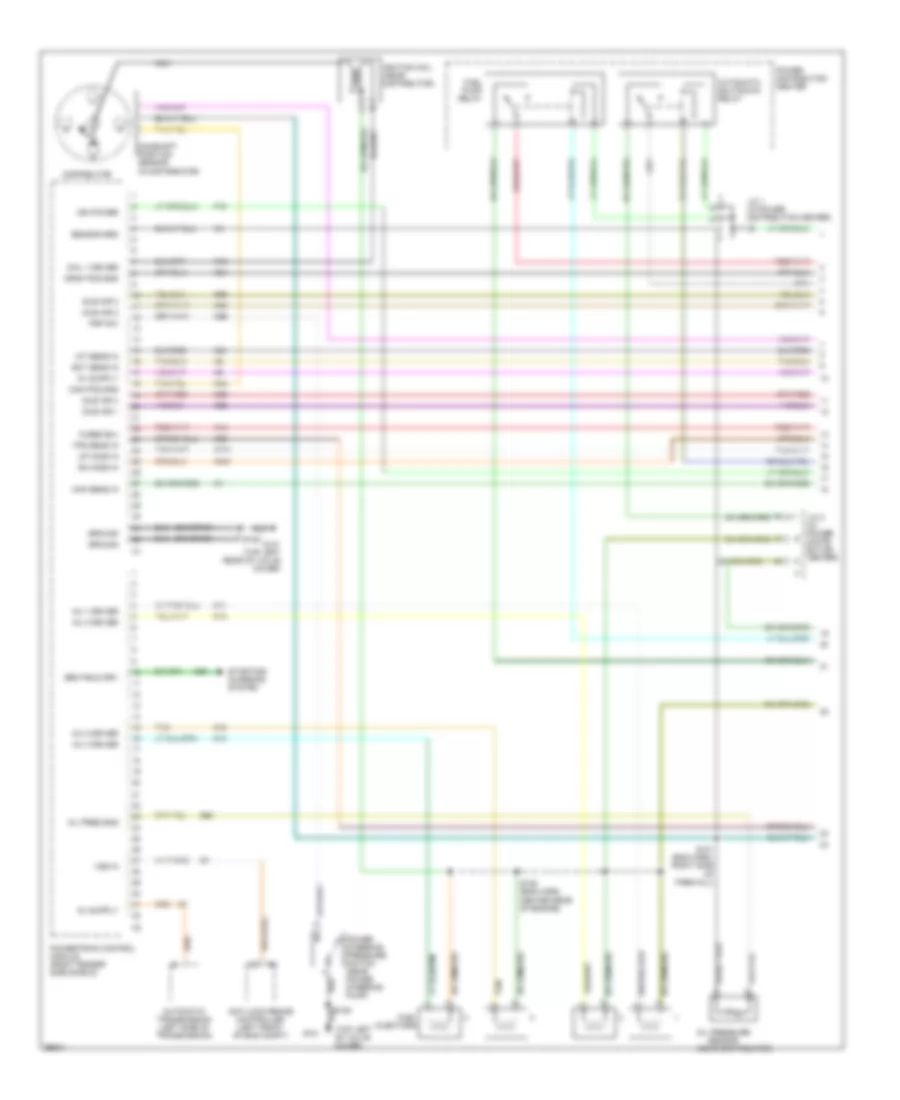
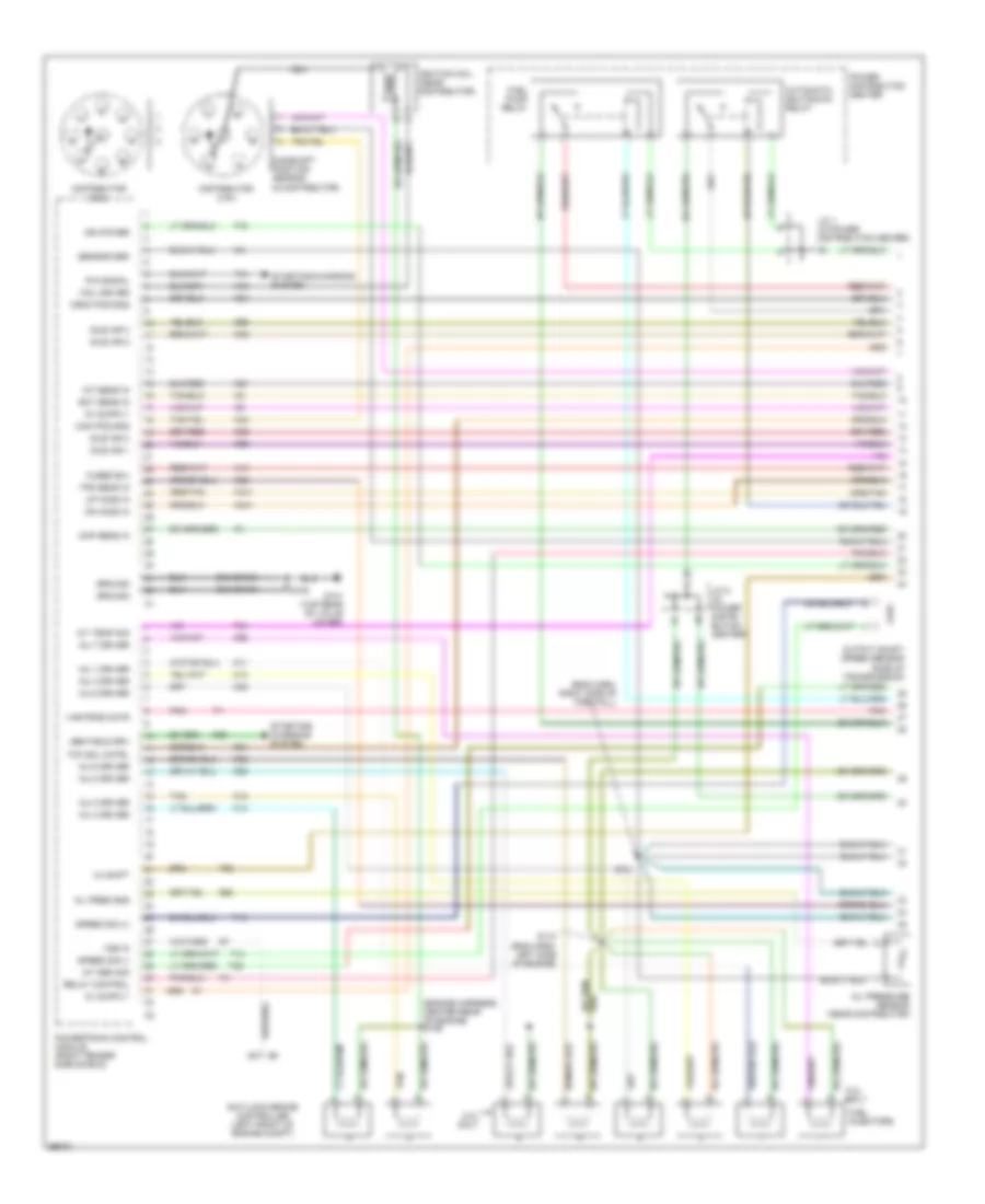
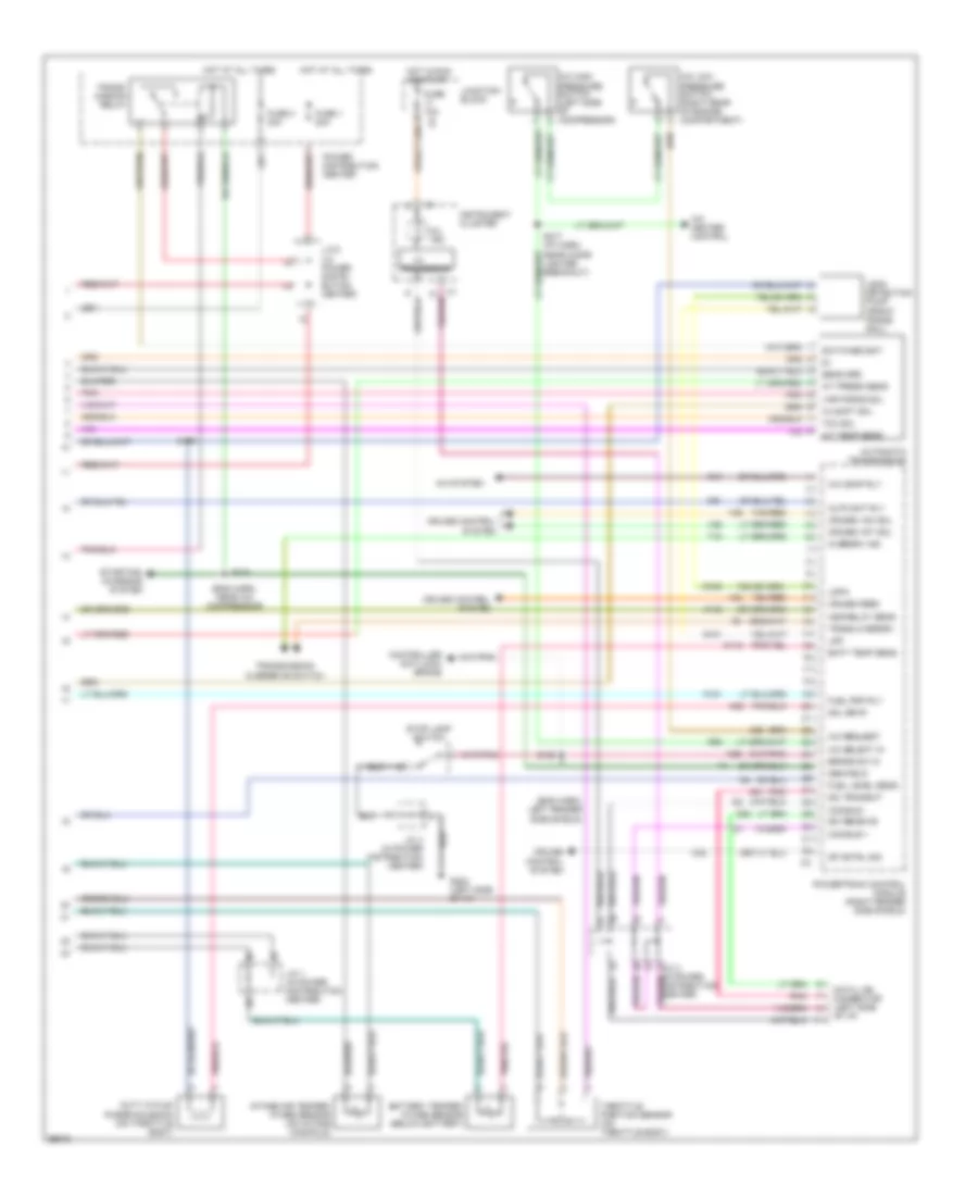
2.5L, Engine Performance Wiring Diagrams (1 of 3) for Dodge Dakota R/T 1998
List of elements for 2.5L, Engine Performance Wiring Diagrams (1 of 3) for Dodge Dakota R/T 1998:
- (in distributor)
- (near distributor)
- (top left of valve cover)
- A14
- Anti-lock brake controller (left front of eng compt)
- Automatic shutdown relay
- Automatic transmission (left side of transmission)
- Cam pos sns
- Camshaft position sensor
- Coil 1 driver
- Crnk pos sns
- Distributor
- Dn ho2s in
- Ect sens in
- F18
- Fuel injectors
- Fuel pump relay
- Fused b(+)
- G131 (top left rear of valve cover)
- G60
- Gen field drv
- Ground
- Iat sens in
- Idle air 1
- Idle air 2
- Idle air 3
- Idle air 4
- Ign power
- Ignition coil (near distributor)
- Inj 1 driver
- Inj 2 driver
- Inj 3 driver
- Inj 4 driver
- J/c 1 (in power distribution center)
- J/c 2 (in power distri- bution center)
- K11
- K12
- K13
- K14
- K141
- K19
- K20
- K21
- K22
- K24
- K341
- K39
- K40
- K44
- K59
- K60
- K99
- Map sens in
- Nca
- Oil pres sns
- Oil pressure sensor
- Power distribution center
- Power steering pressure switch (near power steering pump)
- Powertrain control module (right fender side shield)
- Psp sw
- S101 (eng harn, right side of firewall)
- S105
- S106 (eng harn, center rear of engine)
- S108
- Sensor grd
- Starting/ charging system
- Tan
- Tps sens in
- Up ho2s in
- Vss in
- Z12 (or z1)
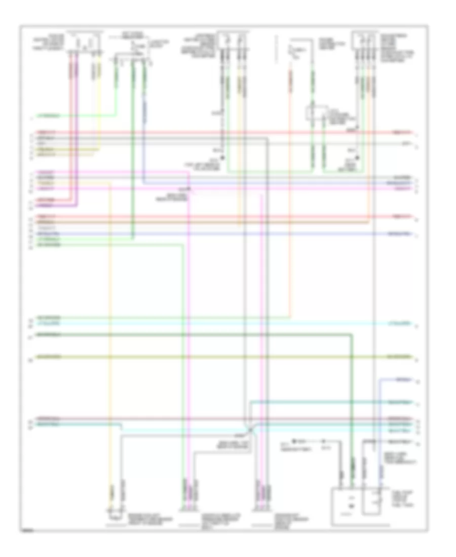
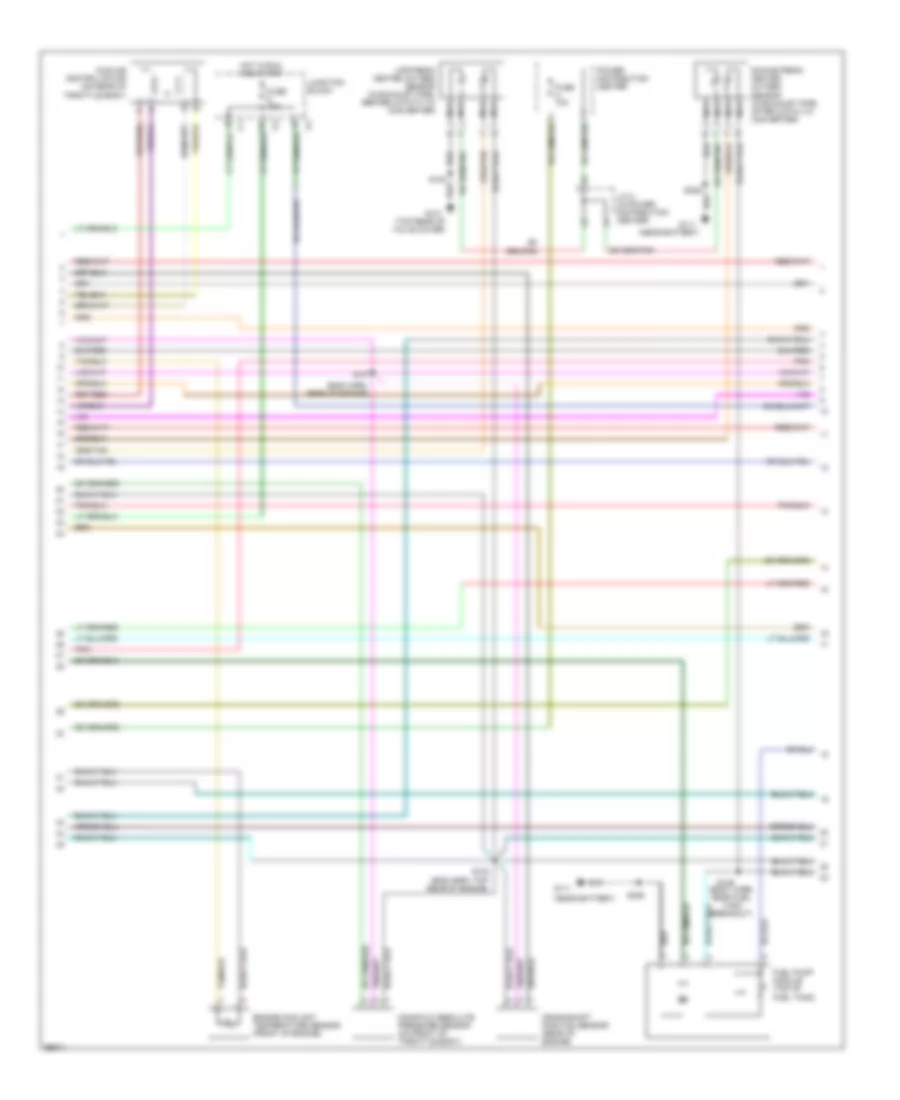
2.5L, Engine Performance Wiring Diagrams (2 of 3) for Dodge Dakota R/T 1998
List of elements for 2.5L, Engine Performance Wiring Diagrams (2 of 3) for Dodge Dakota R/T 1998:
- (body harn, near fuel tank breakout)
- (eng harn, rear of engine)
- (eng harn, top rear of engine)
- (near
- (near battery)
- (top left rear of valve cover)
- Battery)
- Crankshaft position sensor (rear of engine)
- Downstream heated oxygen sensor (in exhaust pipe, after catalyic converter)
- Engine coolant temperature sensor (front of engine)
- Fuel pump module (top of fuel tank)
- Fuse 10a
- Fuse a 10a
- G111
- G131
- Hot in run and start
- Idle air control motor (on side of throttle body)
- J/c 2 (in power distribution center)
- Junction block
- Manifold absolute pressure sensor (on throttle body)
- Nca
- Power distribution center
- S103
- S107
- S108
- S113
- S149
- S306
- Upstream heated oxygen sensor (in exhaust pipe, before catalyic converter)
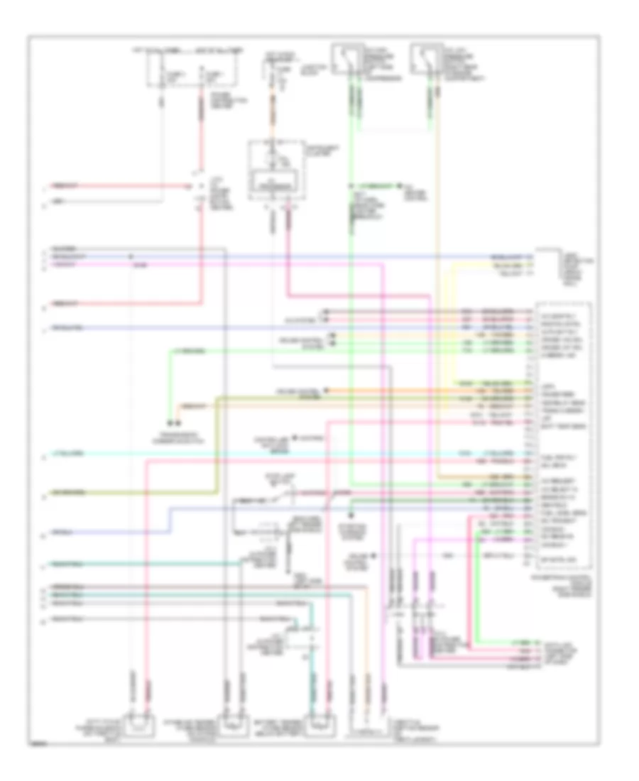
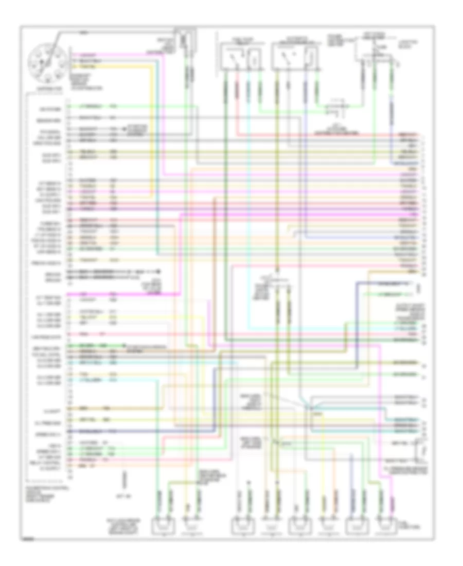
2.5L, Engine Performance Wiring Diagrams (3 of 3) for Dodge Dakota R/T 1998
List of elements for 2.5L, Engine Performance Wiring Diagrams (3 of 3) for Dodge Dakota R/T 1998:
- (eng harn, left fender side shield)
- A/c comp rly
- A/c heater control
- A/c high pressure switch (left side of compressor)
- A/c low pressure switch (right rear of engine compartment)
- A/c request
- A/c select in
- A/c system
- A142
- Asd relay sens
- Auto sht rly
- Batt temp sens
- Battery temper- ature sensor (below battery)
- Brake sw in
- C13
- C20
- C27
- C32
- C90
- Ccd bus +
- Ccd bus -
- Controller anti-lock brake
- Cruise control system
- Cruise feed
- Cruise vac sol
- Cruise vnt sol
- D20
- D21
- Data link connector (left side of dash)
- Duty cycle/ purge solenoid (on throttle body)
- Fuel level sens
- Fuel pmp rly
- Fuse 1 20a
- Fuse 10a
- Fuse 3 30a
- G100
- G101
- G202 (left side of i/p)
- Gen field
- Hot at all times
- Hot in run or start
- I/o
- Instrument cluster
- Intake air temper- ature sensor (on intake manifold)
- J/c 1 (in power distribution center)
- J/c 2 (in power distri- bution center)
- J/c 3 (in power distribution center)
- J/c 4 (in power distribution center)
- Junction block
- K118
- K151
- K29
- K51
- K52
- Ldp
- Ldpa
- Leak detection pump (front frame rail)
- Mil ind.
- Overdrv ind
- Pnk
- Power distribution center
- Powertrain control module (right fender side shield)
- Processor
- Rad fan cntrl
- S129
- S158
- S217 (i/p harn, near cigar lighter breakout)
- Sci receive
- Sci transmit
- Sol drvr
- Sp cntrl sig
- Starting/ charging system
- Stop lamp switch
- T18
- Tan/red
- Throttle position sensor (on throtlle body)
- Trans overdrv
- Transmission overdrive switch
- V32
- V35
- V36
3.9L
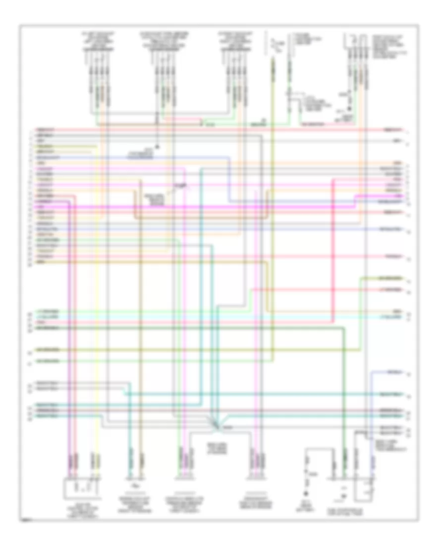
3.9L, Engine Performance Wiring Diagrams (1 of 3) for Dodge Dakota R/T 1998
List of elements for 3.9L, Engine Performance Wiring Diagrams (1 of 3) for Dodge Dakota R/T 1998:
- (eng harn, right side of firewall)
- (engine harness, center rear of engine) s106
- (in distributor)
- 3-4 shift
- 5.2l only
- A/t sen sig
- A/t temp sig
- A14
- Anti-lock brake controller (left front of engine compt)
- Automatic shutdown relay
- Cam pos sns
- Camshaft position sensor
- Coil driver
- Crnk pos sns
- Distributor (3.9l)
- Distributor (5.2l)
- Dn ho2s in
- Ect sens in
- F18
- Fuel injectors
- Fuel pump relay
- Fused b(+)
- G131 (top rear of valve cover)
- G60
- Gen field drv
- Ground
- Iat sens in
- Idle air 1
- Idle air 2
- Idle air 3
- Idle air 4
- Ign power
- Ignition coil (near distributor)
- Inj 1 driver
- Inj 2 driver
- Inj 3 driver
- Inj 4 driver
- Inj 5 driver
- Inj 6 driver
- Inj 7 driver
- Inj 8 driver
- J/c 1 (in power distribution center)
- J/c 2 (in power distri- bution center)
- K11
- K12
- K13
- K14
- K19
- K20
- K21
- K22
- K24
- K26
- K28
- K341
- K38
- K39
- K40
- K44
- K441
- K54
- K58
- K59
- K60
- Map sens in
- Nca
- Oil pres sns
- Oil pressure sensor (near distributor)
- Output shaft speed sensor (side of transmission)
- P/n signal
- Pnk
- Power distribution center
- Powertrain control module (right fender side shield)
- Relay control
- S101
- S105
- S110 (eng harn, left side of engine)
- Sensor grd
- Speed sig (+)
- Speed sig (-)
- Starting/ charging system
- Starting/charging system
- T13
- T14
- T25
- T34
- T41
- T60
- Tan
- Tcc sol cntrl
- Tps sens in
- Up ho2s in
- Var frce cntr
- Vss in
- Z12 (or z1)
3.9L, Engine Performance Wiring Diagrams (2 of 3) for Dodge Dakota R/T 1998
List of elements for 3.9L, Engine Performance Wiring Diagrams (2 of 3) for Dodge Dakota R/T 1998:
- (eng harn, rear of engine)
- (eng harn, top rear of engine)
- (near battery)
- (top rear of valve cover)
- Crankshaft position sensor (rear of engine)
- Downstream heated oxygen sensor (in exhaust pipe, after catalyic converter)
- Engine coolant temperature sensor (front of engine)
- Fuel pump module (top of fuel tank)
- Fuse 10a
- Fuse a 10a
- G111
- G131
- Hot in run and start
- Idle air control motor (on rear of throttle body)
- J/c 2 (in power distribution center)
- Junction block
- Manifold absolute pressure sensor (on front of throttle body)
- Nca
- Pnk
- Power distribution center
- S103
- S107
- S108
- S149 (body harn, near fuel tank breakout)
- S306
- Upstream heated oxygen sensor (in exhaust pipe, before catatytic converter)
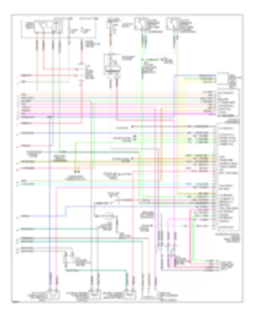
3.9L, Engine Performance Wiring Diagrams (3 of 3) for Dodge Dakota R/T 1998
List of elements for 3.9L, Engine Performance Wiring Diagrams (3 of 3) for Dodge Dakota R/T 1998:
- (eng harn, left fender side shield)
- (eng harn, near a/c compressor)
- 3-4 shft sol
- A/c comp rly
- A/c heater control
- A/c high pressure switch (left side of compressor)
- A/c low pressure switch (right rear of engine compartment)
- A/c request
- A/c select in
- A/c system
- A/t press sens
- A/t temp sens
- A142
- Asd relay sens
- Auto sht rly
- Automatic transmission
- Batt temp sens
- Battery temper- ature sensor (below battery)
- Brake sw in
- C13
- C20
- C32
- C90
- Ccd bus +
- Ccd bus -
- Controller anti-lock brake
- Cruise control system
- Cruise feed
- Cruise vac sol
- Cruise vnt sol
- D20
- D21
- Data link connector (left side of i/p)
- Distribution center)
- Duty cycle/ purge solenoid (on throttle body)
- Fuel level sens
- Fuel pmp rly
- Fuse 1 20a
- Fuse 10a
- Fuse 3 30a
- G100
- G101
- G202 (left side of i/p)
- Gen field
- Hot at all times
- Hot in run or start
- I/o
- Instrument cluster
- Intake air temper- ature sensor (on intake manifold)
- J/c 1 (in power distribution center)
- J/c 2 (in power distri- bution center)
- J/c 3 (in power
- J/c 4 (in power distribution center)
- Junction block
- K118
- K151
- K29
- K51
- K52
- Ldp
- Ldpa
- Leak detection pump (front frame rail)
- Mil ind.
- Overdrv ind
- Pnk
- Power distribution center
- Powertrain control module (right fender side shield)
- Processor
- S104
- S129
- S158
- S217 (i/p harn, near cigar lighter breakout)
- Sci receive
- Sci transmit
- Sens grd
- Sol drvr
- Sp cntrl sig
- Starting/ charging system
- Stop lamp switch
- Switched bat
- T18
- Tan/red
- Tcc sol
- Throttle position sensor (on throttle body)
- Trans overdrv
- Trans- mission relay
- Transmission overdrive switch
- V32
- V35
- V36
- Var force sol
5.2L
5.2L, Engine Performance Wiring Diagrams (1 of 3) for Dodge Dakota R/T 1998
List of elements for 5.2L, Engine Performance Wiring Diagrams (1 of 3) for Dodge Dakota R/T 1998:
- (eng harn, right side of firewall)
- (engine harness, center rear of engine) s106
- (in distributor)
- 3-4 shift
- 5.2l only
- A/t sen sig
- A/t temp sig
- A14
- Anti-lock brake controller (left front of engine compt)
- Automatic shutdown relay
- Cam pos sns
- Camshaft position sensor
- Coil driver
- Crnk pos sns
- Distributor (3.9l)
- Distributor (5.2l)
- Dn ho2s in
- Ect sens in
- F18
- Fuel injectors
- Fuel pump relay
- Fused b(+)
- G131 (top rear of valve cover)
- G60
- Gen field drv
- Ground
- Iat sens in
- Idle air 1
- Idle air 2
- Idle air 3
- Idle air 4
- Ign power
- Ignition coil (near distributor)
- Inj 1 driver
- Inj 2 driver
- Inj 3 driver
- Inj 4 driver
- Inj 5 driver
- Inj 6 driver
- Inj 7 driver
- Inj 8 driver
- J/c 1 (in power distribution center)
- J/c 2 (in power distri- bution center)
- K11
- K12
- K13
- K14
- K19
- K20
- K21
- K22
- K24
- K26
- K28
- K341
- K38
- K39
- K40
- K44
- K441
- K54
- K58
- K59
- K60
- Map sens in
- Nca
- Oil pres sns
- Oil pressure sensor (near distributor)
- Output shaft speed sensor (side of transmission)
- P/n signal
- Pnk
- Power distribution center
- Powertrain control module (right fender side shield)
- Relay control
- S101
- S105
- S110 (eng harn, left side of engine)
- Sensor grd
- Speed sig (+)
- Speed sig (-)
- Starting/ charging system
- Starting/charging system
- T13
- T14
- T25
- T34
- T41
- T60
- Tan
- Tcc sol cntrl
- Tps sens in
- Up ho2s in
- Var frce cntr
- Vss in
- Z12 (or z1)
5.2L, Engine Performance Wiring Diagrams (2 of 3) for Dodge Dakota R/T 1998
List of elements for 5.2L, Engine Performance Wiring Diagrams (2 of 3) for Dodge Dakota R/T 1998:
- (eng harn, rear of engine)
- (eng harn, top rear of engine)
- (near battery)
- (top rear of valve cover)
- Crankshaft position sensor (rear of engine)
- Downstream heated oxygen sensor (in exhaust pipe, after catalyic converter)
- Engine coolant temperature sensor (front of engine)
- Fuel pump module (top of fuel tank)
- Fuse 10a
- Fuse a 10a
- G111
- G131
- Hot in run and start
- Idle air control motor (on rear of throttle body)
- J/c 2 (in power distribution center)
- Junction block
- Manifold absolute pressure sensor (on front of throttle body)
- Nca
- Pnk
- Power distribution center
- S103
- S107
- S108
- S149 (body harn, near fuel tank breakout)
- S306
- Upstream heated oxygen sensor (in exhaust pipe, before catatytic converter)
5.2L, Engine Performance Wiring Diagrams (3 of 3) for Dodge Dakota R/T 1998
List of elements for 5.2L, Engine Performance Wiring Diagrams (3 of 3) for Dodge Dakota R/T 1998:
- (eng harn, left fender side shield)
- (eng harn, near a/c compressor)
- 3-4 shft sol
- A/c comp rly
- A/c heater control
- A/c high pressure switch (left side of compressor)
- A/c low pressure switch (right rear of engine compartment)
- A/c request
- A/c select in
- A/c system
- A/t press sens
- A/t temp sens
- A142
- Asd relay sens
- Auto sht rly
- Automatic transmission
- Batt temp sens
- Battery temper- ature sensor (below battery)
- Brake sw in
- C13
- C20
- C32
- C90
- Ccd bus +
- Ccd bus -
- Controller anti-lock brake
- Cruise control system
- Cruise feed
- Cruise vac sol
- Cruise vnt sol
- D20
- D21
- Data link connector (left side of i/p)
- Distribution center)
- Duty cycle/ purge solenoid (on throttle body)
- Fuel level sens
- Fuel pmp rly
- Fuse 1 20a
- Fuse 10a
- Fuse 3 30a
- G100
- G101
- G202 (left side of i/p)
- Gen field
- Hot at all times
- Hot in run or start
- I/o
- Instrument cluster
- Intake air temper- ature sensor (on intake manifold)
- J/c 1 (in power distribution center)
- J/c 2 (in power distri- bution center)
- J/c 3 (in power
- J/c 4 (in power distribution center)
- Junction block
- K118
- K151
- K29
- K51
- K52
- Ldp
- Ldpa
- Leak detection pump (front frame rail)
- Mil ind.
- Overdrv ind
- Pnk
- Power distribution center
- Powertrain control module (right fender side shield)
- Processor
- S104
- S129
- S158
- S217 (i/p harn, near cigar lighter breakout)
- Sci receive
- Sci transmit
- Sens grd
- Sol drvr
- Sp cntrl sig
- Starting/ charging system
- Stop lamp switch
- Switched bat
- T18
- Tan/red
- Tcc sol
- Throttle position sensor (on throttle body)
- Trans overdrv
- Trans- mission relay
- Transmission overdrive switch
- V32
- V35
- V36
- Var force sol
5.9L
5.9L, Engine Performance Wiring Diagrams (1 of 3) for Dodge Dakota R/T 1998
List of elements for 5.9L, Engine Performance Wiring Diagrams (1 of 3) for Dodge Dakota R/T 1998:
- (eng harn, center rear of engine) s106
- (eng harn, left side of engine)
- (eng harn, right side of firewall)
- (in distributor)
- 3-4 shift
- A/t sen sig
- A/t temp sig
- A14
- Anti-lock brake controller (left front of engine compt)
- Automatic shutdown relay
- Cam pos sns
- Camshaft position sensor
- Coil driver
- Crnk pos sns
- Distributor
- Ect sens in
- F18
- Fuel injectors
- Fuel pump relay
- Fuse 10a
- Fused b(+)
- G131 (top rear of valve cover)
- G60
- Gen field drv
- Ground
- Hot in run and start
- Iat sens in
- Idle air 1
- Idle air 2
- Idle air 3
- Idle air 4
- Ign power
- Ignition coil (near distributor)
- Inj 1 driver
- Inj 2 driver
- Inj 3 driver
- Inj 4 driver
- Inj 5 driver
- Inj 6 driver
- Inj 7 driver
- Inj 8 driver
- J/c 1 (in power distribution center)
- J/c 2 (in power distri- bution center)
- Junction block
- K11
- K12
- K13
- K14
- K141
- K19
- K20
- K21
- K22
- K24
- K241
- K26
- K28
- K341
- K38
- K39
- K40
- K44
- K441
- K54
- K58
- K59
- K60
- Lt up ho2s in
- Map sens in
- Nca
- Oil pres sns
- Oil pressure sensor (near distributor)
- Output shaft speed sensor (side of transmission)
- P/n signal
- Pnk
- Pos dn ho2s in
- Power distribution center
- Powertrain control module (right fender side shield)
- Pre dn ho2s in
- Relay control
- Rt up ho2s in
- S101
- S105
- S110
- Sensor grd
- Speed sig (+)
- Speed sig (-)
- Starting/ charging system
- Starting/charging system
- T13
- T14
- T25
- T34
- T41
- T60
- Tan
- Tcc sol cntrl
- Tps sens in
- Var frce cntr
- Vss in
- Z12 (or z1)
5.9L, Engine Performance Wiring Diagrams (2 of 3) for Dodge Dakota R/T 1998
List of elements for 5.9L, Engine Performance Wiring Diagrams (2 of 3) for Dodge Dakota R/T 1998:
- (body harn, near fuel tank breakout)
- (eng harn, rear of engine)
- (eng harn, top rear of engine)
- (in exhaust pipe, before catalytic converter) pre-catalyst downstream heated oxygen sensor
- (in left exhaust downpipe) left upstream heated oxygen sensor
- (in right exhaust downpipe) right upstream heated oxygen sensor
- (near battery)
- Crankshaft position sensor (rear of engine)
- Engine coolant temperature sensor (front of engine)
- Fuel pump module (top of fuel tank)
- Fuse a 10a
- G111
- G111 (near battery)
- G131 (top rear of valve cover)
- Idle air control motor (on rear of throttle body)
- J/c 2 (in power distribution center)
- Manifold absolute pressure sensor (on front of throttle body)
- Nca
- Pnk
- Post-catalyst downstream heated oxygen sensor (after catalytic converter)
- Power distribution center
- S103
- S107
- S130
- S149
- S306
5.9L, Engine Performance Wiring Diagrams (3 of 3) for Dodge Dakota R/T 1998
List of elements for 5.9L, Engine Performance Wiring Diagrams (3 of 3) for Dodge Dakota R/T 1998:
- (eng harn, left fender side shield)
- (eng harn, near a/c compressor)
- 3-4 shft sol
- A/c comp rly
- A/c heater control
- A/c high pressure switch (left side of compressor)
- A/c low pressure switch (right rear of engine compartment)
- A/c request
- A/c select in
- A/c system
- A/t press sens
- A/t temp sens
- A142
- Asd relay sens
- Auto sht rly
- Automatic transmission
- Batt temp sens
- Battery temper- ature sensor (below battery)
- Brake sw in
- C13
- C20
- C32
- C90
- Ccd bus +
- Ccd bus -
- Controller anti-lock brake
- Cruise control system
- Cruise feed
- Cruise vac sol
- Cruise vnt sol
- D20
- D21
- Data link connector (left side of i/p)
- Distribution center)
- Duty cycle/ purge solenoid (on throttle body)
- Fuel level sens
- Fuel pmp rly
- Fuse 1 20a
- Fuse 10a
- Fuse 3 30a
- G100
- G101
- G202 (left side of i/p)
- Gen field
- Hot at all times
- Hot in run or start
- I/o
- Instrument cluster
- Intake air temper- ature sensor (on intake manifold)
- J/c 1 (in power distribution center)
- J/c 2 (in power distri- bution center)
- J/c 3 (in power
- J/c 4 (in power distribution center)
- Junction block
- K118
- K151
- K29
- K51
- K52
- Ldp
- Ldpa
- Leak detection pump (front frame rail)
- Mil ind.
- Overdrv ind
- Pnk
- Power distribution center
- Powertrain control module (right fender side shield)
- Processor
- S104
- S129
- S158
- S217 (i/p harn, near cigar lighter breakout)
- Sci receive
- Sci transmit
- Sens grd
- Sol drvr
- Sp cntrl sig
- Starting/ charging system
- Stop lamp switch
- Switched bat
- T18
- Tan/red
- Tcc sol
- Throttle position sensor (on throttle body)
- Trans overdrv
- Trans- mission relay
- Transmission overdrive switch
- V32
- V35
- V36
- Var force sol

 Čeština
 Dansk
Dansk Deutsch
 Ελληνικά
 English
 English
 Español
 Suomi
Suomi Français
 Français
 עברית
עברית Hrvatski
 Magyar
 日本語
日本語 한국어
한국어 Nederlands
 Polski
 Português
 Português
 Română
 Русский
 Slovenčina
 Slovenščina
 Svenska
 Türkçe
 中文 (中国)