
 Čeština
 Dansk
Dansk Deutsch
 Ελληνικά
 English
 English
 Español
 Suomi
Suomi Français
 Français
 עברית
עברית Hrvatski
 Magyar
 日本語
日本語 한국어
한국어 Nederlands
 Polski
 Português
 Português
 Română
 Русский
 Slovenčina
 Slovenščina
 Svenska
 Türkçe
 中文 (中国)

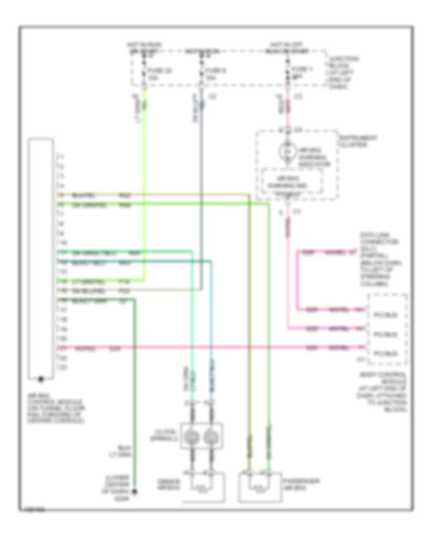
SUPPLEMENTAL RESTRAINTS
Supplemental Restraint Wiring Diagram for Dodge Intrepid R/T 2000
List of elements for Supplemental Restraint Wiring Diagram for Dodge Intrepid R/T 2000:

ANTI-LOCK BRAKESANTI-THEFTAIR CONDITIONINGBODY COMPUTERCOOLING FANDEFOGGERSELECTRONIC POWER STEERINGCRUISE CONTROLCOMPUTER DATA LINESHORNGROUND DISTRIBUTIONEXTERIOR LIGHTSPOWER DOOR LOCKSENGINE PERFORMANCEINSTRUMENT CLUSTERPOWER WINDOWSHEADLIGHTSPOWER MIRRORSINTERIOR LIGHTSRADIOPOWER SEATSPOWER DISTRIBUTIONSHIFT INTERLOCKSPOWER TOP/SUNROOFTRUNK, TAILGATE, FUEL DOORSUPPLEMENTAL RESTRAINTSSTARTING/CHARGINGTRANSMISSIONWARNING SYSTEMSWIPER/WASHER