SUPPLEMENTAL RESTRAINTS
Supplemental Restraints Wiring Diagram for Buick Park Avenue 2005
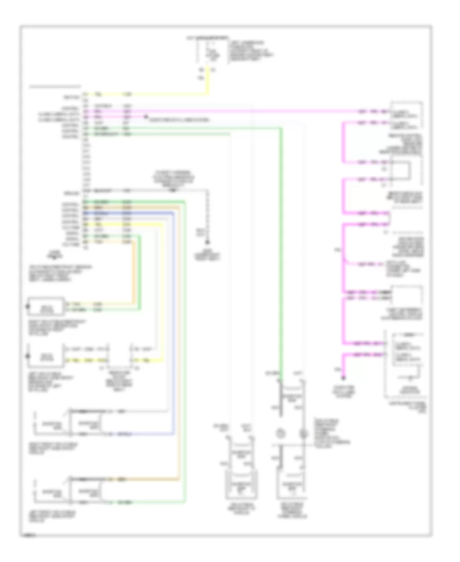
List of elements for Supplemental Restraints Wiring Diagram for Buick Park Avenue 2005:
- (in body harness, 15 cm from sensing & diagnostic module breakout) s307
- A10
- A11
- A12
- A13
- A14
- A15
- A16
- A17
- A18
- Air bag indicator
- B11
- B12
- Case ground
- Class 2 serial data
- Computer data lines system
- Control
- D11
- Data link connector (under left side of dash)
- Driver door module (ddm) (inside driver's door, above radio speaker)
- F11
- F12
- G306 (under right front seat)
- Ground
- Hot in run or start
- Ignition
- Inflatable restraint i/p module
- Inflatable restraint sensing & diagnostic module (sdm) (below right front seat, under carpet)
- Inflatable restraint steering wheel module
- Inflatable restraint steering wheel module coil (top of steering column)
- Instrument panel cluster (ipc)
- Left front inflatable restraint side impact module
- Left inflatable restraint side impact sensor (sis) (on base of left "b" pillar)
- Left underhood fuse block (on right front of engine compartment, near battery)
- Logig
- Nca
- Rear fuse block (below right side of rear seat)
- Remote control door lock receiver (under center of rear package shelf)
- Right front inflatable restraint side impact module
- Right inflatable restraint side impact sensor (sis) (on base of right "b" pillar)
- Shorting bar
- Signal
- Sir fuse 10a
- Solid state
- Tan
- Theft deterrent control module (in steering column)
- Voltage
 Čeština
 Dansk
Dansk Deutsch
 Ελληνικά
 English
 English
 Español
 Suomi
Suomi Français
 Français
 עברית
עברית Hrvatski
 Magyar
 日本語
日本語 한국어
한국어 Nederlands
 Polski
 Português
 Português
 Română
 Русский
 Slovenčina
 Slovenščina
 Svenska
 Türkçe
 中文 (中国)
 Italiano