AIR CONDITIONING
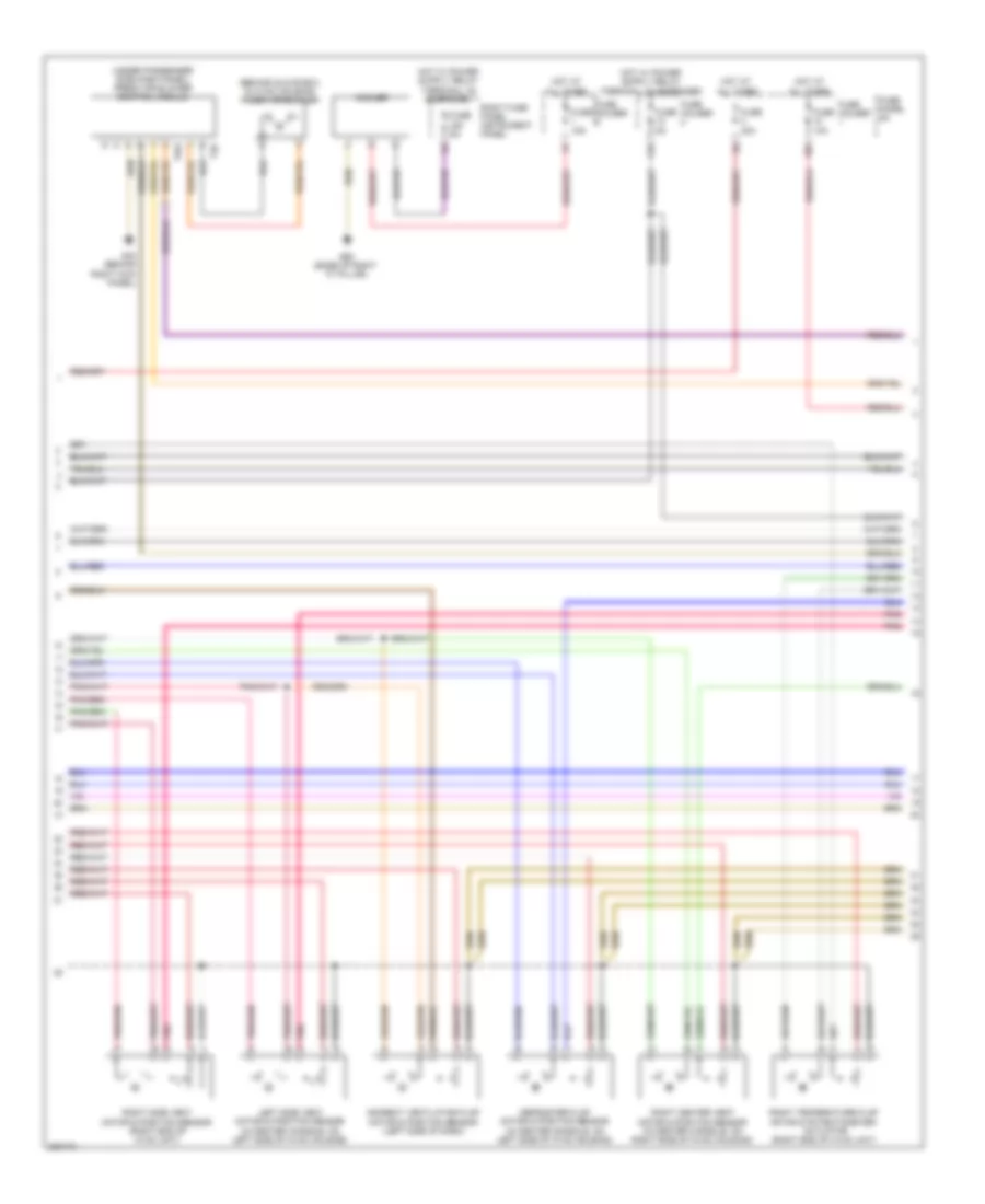
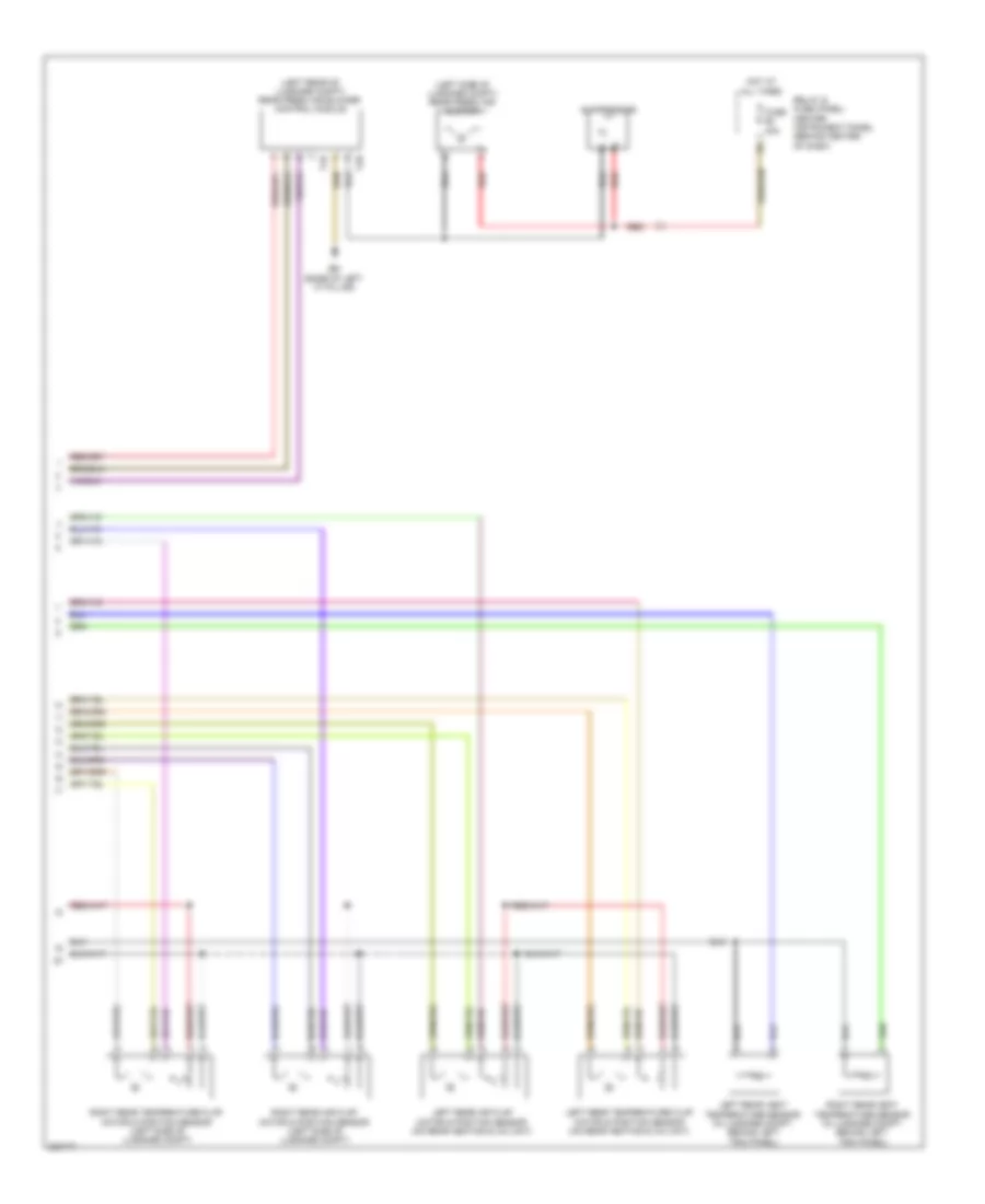
Automatic A/C Wiring Diagram (1 of 4) for Audi Q7 4.2 2010
 https://portal-diagnostov.com/license.html
Automotive Electricians Portal FZCO
Automotive Electricians Portal FZCO
https://portal-diagnostov.com/license.html
https://portal-diagnostov.com/license.html
Automotive Electricians Portal FZCO
Automotive Electricians Portal FZCO
List of elements for Automatic A/C Wiring Diagram (1 of 4) for Audi Q7 4.2 2010:
- (left rear of engine compt, on fresh air intake grille) air quality sensor
- A/c compressor regulator valve
- Climatronic control module
- Computer data lines system
- G45 (behind center of dash)
- Left center vent motor & position sensor (in center console, on left side of hvac housing)
- Left footwell flap motor & position sensor (in center console, on left side of hvac housing)
- Left temperature flap motor & potentiometer/ actuator (in center console, on left side of hvac housing)
- Recirculation flap motor & position sensor (right side of dash)
- Right footwell flap motor & position sensor (right side of hvac unit)
- Seats system
- T16c
- T20i
- T3c
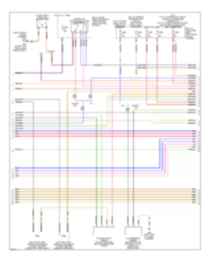
Automatic A/C Wiring Diagram (2 of 4) for Audi Q7 4.2 2010
List of elements for Automatic A/C Wiring Diagram (2 of 4) for Audi Q7 4.2 2010:
- (behind glove box, in hvac housing) fresh air blower
- (under passenger side dash panel) fresh air blower control module
- 10a
- 12a
- Cooler
- Defroster flap motor & position sensor (in center console, on left side of hvac housing)
- Fuse 10a
- Fuse 15a
- Fuse 30a
- Fuse 5a
- Fuse holder
- Fuse panel sc
- G43 (behind right kick panel)
- G62 (base of right "c" pillar)
- Hot at all times
- Indirect ventilation flap motor & position sensor (left side of dash)
- Left side vent motor & position sensor (in center console, on left side of hvac housing)
- Pnk
- Right center vent motor & position sensor (in center console, on right side of hvac housing)
- Right fuse panel instrument panel
- Right side vent motor & position sensor (right end of hvac unit)
- Right temperature flap motor & potentiometer/ actuator (right end of hvac unit)
- T2q
- T6ai
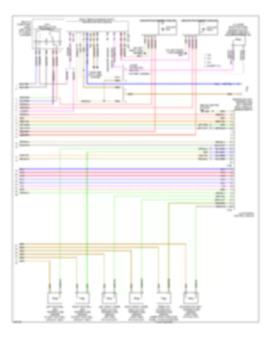
Automatic A/C Wiring Diagram (3 of 4) for Audi Q7 4.2 2010
List of elements for Automatic A/C Wiring Diagram (3 of 4) for Audi Q7 4.2 2010:
- (except 3.6l) coolant circulation pump relay
- (in left front wheelwell) coolant pump
- (right side of plenum chamber) (3.6l) g609
- 10a
- 13a
- 3.0l
- 3.6l
- Except 3.0l
- Except 3.6l
- Fuse 10a
- Fuse 13a
- Fuse 40a
- Fuse 5a
- Fuse 60a
- G609 (right side of plenum chamber)
- G640 (except 3.6l) (left side of engine compt)
- High pressure sensor (on evaporator expansion valve, under right side of dash)
- Hot at all times
- Left front seat temperature sensor (w/ seat heater) (under driver's seat)
- Pnk
- Relay & fuse panel e-box (left side of plenum chamber)
- Relay & fuse panel/instrument panel center (behind center of dash)
- Right front seat temperature sensor (w/ seat heater) (under right front seat)
- Sunlight photo sensor (top of dash panel, between defroster vents)
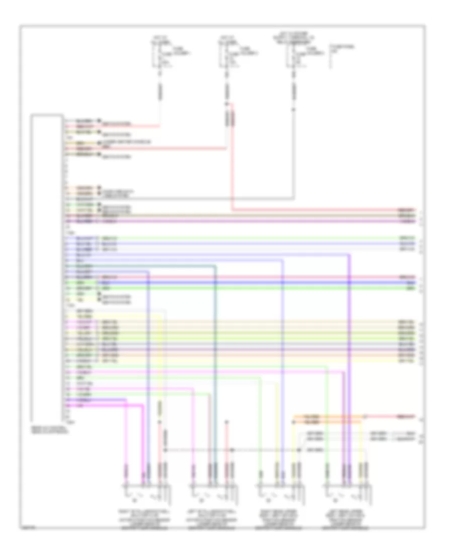
Automatic A/C Wiring Diagram (4 of 4) for Audi Q7 4.2 2010
List of elements for Automatic A/C Wiring Diagram (4 of 4) for Audi Q7 4.2 2010:
- (3.6l) recirculation pump relay
- (behind center of dash) g45
- (in upper radiator hose) engine coolant temperature (ect) sensor (on radiator)
- (on left front long member) g671
- (right rear of engine compt) engine control module
- 19a
- 19b
- 19c
- 19d
- 19e
- 3.0l
- 3.6l
- 4.2l
- Climatronic control module
- Computer data lines system
- Coolant fan
- Coolant fan 2
- Coolant fan control module
- Coolant fan control module 2
- Engine coolant temperature (ect) sensor (right rear of engine compt)
- Evaporator vent temperature sensor (right end of hvac unit)
- Except 3.0l
- Fresh air intake duct temperature sensor (under right side dash panel, in air intake for hvac housing)
- Left footwell vent temperature sensor (in left footwell air duct vent)
- Left front upper body outlet temperature sensor (left end of hvac unit)
- Pnk
- Relay & fuse panel e-box (left side of plenum chamber)
- Right footwell vent temperature sensor (in right footwell air duct vent)
- Right front upper body outlet temperature sensor (right end of hvac unit)
- T12g
- T16d
- T60
- T94
Rear A/C Wiring Diagram (1 of 2) for Audi Q7 4.2 2010
List of elements for Rear A/C Wiring Diagram (1 of 2) for Audi Q7 4.2 2010:
- (under center console) g687
- 12a
- Computer data lines system
- Fuse 10a
- Fuse 20a
- Fuse 5a
- Fuse holder 1
- Fuse holder 2
- Fuse holder 3
- Fuse panel sc
- Hot at all times
- Left "b" pillar/footwell shut-off flap motor & position sensor (under rear of center floor console)
- Left rear upper body vent motor & position sensor (under rear of center floor console)
- Rear a/c control head (climatronic)
- Right "b" pillar/footwell shut-off flap motor & position sensor (under rear of center floor console)
- Right rear upper body vent motor & position sensor (under rear of center floor console)
- Seats system
- T12h
- T16h
- T20h
- T3h
Rear A/C Wiring Diagram (2 of 2) for Audi Q7 4.2 2010
List of elements for Rear A/C Wiring Diagram (2 of 2) for Audi Q7 4.2 2010:
- (left rear of luggage compt) rear fresh air blower control module
- (left side of luggage compt) rear fresh air blower
- Fuse 40a
- G61 (base of left "c" pillar)
- Hot at all times
- Left rear air flap motor & position sensor (on rear heating & a/c unit)
- Left rear temperature flap motor & position sensor (on rear heating & a/c unit)
- Left rear vent temperature sensor (in luggage compt, behind left trim panel)
- Red
- Relay & fuse panel/ center instrument panel (behind center of dash)
- Right rear air flap motor & position sensor (left side of luggage compt)
- Right rear temperature flap motor & position sensor (left side of luggage compt)
- Right rear vent temperature sensor (in luggage compt, behind left trim panel)
- Suppressor
- T2r
- T4u

 Čeština
 Dansk
Dansk Deutsch
 Ελληνικά
 English
 English
 Español
 Suomi
Suomi Français
 Français
 עברית
עברית Hrvatski
 Magyar
 日本語
日本語 한국어
한국어 Nederlands
 Polski
 Português
 Português
 Română
 Русский
 Slovenčina
 Slovenščina
 Svenska
 Türkçe
 中文 (中国)